

Page 1

USER’S MANUAL
Revision 1.0
X9SCE-F
Page 2

Manual Revision 1.0
Release Date: Dec. 10, 2012
Unless you request and receive written permission from Super Micro Computer, Inc., you may not
copy any part of this document. Information in this document is subject to change without notice.
Other products and companies referred to herein are trademarks or registered trademarks of their
respective companies or mark holders.
Copyright © 2012 by Super Micro Computer, Inc.
All rights reserved.
Printed in the United States of America
The information in this User’s Manual has been carefully reviewed and is believed to be accurate.
The vendor assumes no responsibility for any inaccuracies that may be contained in this document,
makes no commitment to update or to keep current the information in this manual, or to notify any
person or organization of the updates. Please Note: For the most up-to-date version of this
manual, please see our web site at www.supermicro.com.
Super Micro Computer, Inc. ("Supermicro") reserves the right to make changes to the product
described in this manual at any time and without notice. This product, including software and documentation, is the property of Supermicro and/or its licensors, and is supplied only under a license.
Any use or reproduction of this product is not allowed, except as expressly permitted by the terms
of said license.
IN NO EVENT WILL SUPERMICRO BE LIABLE FOR DIRECT, INDIRECT, SPECIAL, INCIDENTAL,
SPECULATIVE OR CONSEQUENTIAL DAMAGES ARISING FROM THE USE OR INABILITY TO
USE THIS PRODUCT OR DOCUMENTATION, EVEN IF ADVISED OF THE POSSIBILITY OF
SUCH DAMAGES. IN PARTICULAR, SUPERMICRO SHALL NOT HAVE LIABILITY FOR ANY
HARDWARE, SOFTWARE, OR DATA STORED OR USED WITH THE PRODUCT, INCLUDING THE
COSTS OF REPAIRING, REPLACING, INTEGRATING, INSTALLING OR RECOVERING SUCH
HARDWARE, SOFTWARE, OR DATA.
Any disputes arising between manufacturer and customer shall be governed by the laws of Santa
Clara County in the State of California, USA. The State of California, County of Santa Clara shall
be the exclusive venue for the resolution of any such disputes. Super Micro's total liability for all
claims will not exceed the price paid for the hardware product.
FCC Statement: This equipment has been tested and found to comply with the limits for a class B
digital device, pursuant to Part 15 of the FCC Rules. These limits are designed to provide reasonable
protection against harmful interference in a residential installation. This equipment generates, uses,
and can radiate radio frequency energy and, if not installed and used in accordance with the instructions, may cause harmful interference to radio communications. However, there is no guarantee that
interference will not occur in a particular installation. If this equipment does cause harmful interference to radio or television reception, which can be determined by turning the equipment off and on,
the user is encouraged to try to correct the interference by one or more of the following measures:
•Reorient or relocate the receiving antenna.
•Increase the separation between the equipment and receiver.
•Connect the equipment to an outlet on a circuit different from that to which the receiver
is connected.
•Consult the authorized dealer or an experienced radio/TV technician for help.
California Best Management Practices Regulations for Perchlorate Materials: This Perchlorate warning applies only to products containing CR (Manganese Dioxide) Lithium coin cells. “Perchlorate
Material-special handling may apply. See www.dtsc.ca.gov/hazardouswaste/perchlorate”
WARNING: Handling of lead solder materials used in this
product may expose you to lead, a chemical known to the
State of California to cause birth defects and other reproductive harm.
Page 3

iii
Preface
About This Manual
This manual is written for system integrators, PC technicians and
knowledgeable PC users. It provides information for the installation and use of
the X9SCE-F motherboard product series. This product is intended to be
professionally installed and serviced by a technician.
About This Motherboard
The X9SCE-F motherboard is a proprietary form-factor, high-density motherboard
designed for microcloud node applications.
The X9SCE-F supports an Intel® Xeon E3-1200 & E3-1200 v. 2 series and 3rd Gen.
Core i3 CPU on an H2 socket (LGA 1155) and the Intel C204 PCH chipset. This
motherboard also features support for up to 32 GB DDR3 ECC UDIMMM memory,
two SATA 3.0 ports on the backplane (6 Gb/sec), one 10/100 IPMI LAN, and a
KVM connector on the I/O panel. These features enable the X9SCE-F to deliver a
cost-effective microcloud solution in a small form-factor package.
Manual Organization
Chapter 1 describes the features, specications and performance of the mother-
board and provides detailed information about the C204 chipset.
Chapter 2 provides hardware installation instructions. Read this chapter when in-
stalling the processor, memory modules and other hardware components into the
system. If you encounter any problems, see Chapter 3, which describes trouble-
shooting procedures for video, memory and system setup stored in the CMOS.
Chapter 4 includes an introduction to the BIOS and provides detailed information
on running the CMOS Setup utility.
Appendix A lists Driver Installation Instructions.
Appendix B provides the UEFI BIOS Recovery Instructions.
Preface
Page 4

iv
X9SCE-F User’s Manual
Conventions Used in the Manual:
Special attention should be given to the following symbols for proper installation and
to prevent damage done to the components or injury to yourself:
Warning: Critical information to prevent damage to the components or injury to your-
self.
Important: Important information given to ensure proper system installa-
tion or to relay safety precautions.
Note: Additional Information given to differentiate various models or pro-
vides information for correct system setup.
Page 5

v
Contacting Supermicro
Contacting Supermicro
Headquarters
Address: Super Micro Computer, Inc.
980 Rock Ave.
San Jose, CA 95131 U.S.A.
Tel: +1 (408) 503-8000
Fax: +1 (408) 503-8008
Email: [email protected] (General Information)
[email protected] (Technical Support)
Web Site: www.supermicro.com
Europe
Address: Super Micro Computer B.V.
Het Sterrenbeeld 28, 5215 ML
's-Hertogenbosch, The Netherlands
Tel: +31 (0) 73-6400390
Fax: +31 (0) 73-6416525
Email: [email protected] (General Information)
[email protected] (Technical Support)
[email protected] (Customer Support)
Asia-Pacic
Address: Super Micro Computer, Inc.
4F, No. 232-1, Liancheng Rd
Chung-Ho Dist., New Taipei City 235
Taiwan
Tel: +886-(2) 8226-3990
Fax: +886-(2) 8226-3991
Web Site: www.supermicro.com.tw
Technical Support:
Email: [email protected]
Tel: +886-(2)-8226-3990
Page 6

vi
Table of Contents
Preface
Chapter 1 Introduction
1-1 Overview ......................................................................................................... 1-1
1-2 Chipset Overview ........................................................................................... 1-9
1-3 PC Health Monitoring .................................................................................... 1-10
1-4 Power Supply ................................................................................................ 1-10
1-5 Super I/O ........................................................................................................1-11
Chapter 2 Installation
2-1 Standardized Warning Statements ................................................................. 2-1
2-2 Static-Sensitive Devices .................................................................................. 2-4
2-3 Motherboard Installation .................................................................................. 2-5
Installation Instructions .................................................................................... 2-6
Location of Mounting Holes ............................................................................ 2-5
2-4 System Memory .............................................................................................. 2-8
How to Install DDR3 DIMMs ........................................................................... 2-8
Memory Support .............................................................................................. 2-8
Installing and Removing DIMMs ..................................................................... 2-9
Memory Population Guidelines ..................................................................... 2-10
2-5 Connectors/I/O Ports ......................................................................................2-11
Back Panel Connectors and I/O Ports ...........................................................2-11
UID Button/LED Indicator ......................................................................... 2-12
Power Button & LED ................................................................................ 2-12
KVM Port .................................................................................................. 2-12
IPMI_LAN Port ......................................................................................... 2-12
2-6 Connecting Cables ........................................................................................ 2-13
IF + POWER ............................................................................................ 2-13
SATA DOM Power .................................................................................... 2-13
2-7 Jumper Settings ............................................................................................ 2-14
Explanation of Jumpers ............................................................................ 2-14
CMOS Clear (JBT1) ................................................................................. 2-15
BMC Enable/Disable (JPB1) .................................................................... 2-15
VGA Enable (JPG1) ................................................................................ 2-16
Watch Dog RST/NMI Selection (JWD1)................................................... 2-16
2-8 Onboard Indicators ........................................................................................ 2-17
IPMI Dedicated LAN Port ......................................................................... 2-17
IPMI Heartbeat LED ................................................................................. 2-17
X9SCE-F User’s Manual
Page 7

vii
Table of Contents
Unit ID LED .............................................................................................. 2-18
2-9 SATA Connections ......................................................................................... 2-19
SATA Connections (SATA4) ..................................................................... 2-19
Chapter 3 Troubleshooting
3-1 Troubleshooting Procedures ........................................................................... 3-1
Before Power On ............................................................................................ 3-1
No Power ........................................................................................................ 3-1
No Video ......................................................................................................... 3-1
Memory Errors ............................................................................................... 3-2
If You Lose the System’s Setup Conguration ............................................... 3-2
3-2 Technical Support Procedures ........................................................................ 3-2
3-3 Frequently Asked Questions ........................................................................... 3-3
3-4 Battery Removal and Installation .................................................................... 3-5
Battery Removal .............................................................................................. 3-5
Proper Battery Disposal .................................................................................. 3-5
Battery Installation ........................................................................................... 3-5
3-5 Returning Merchandise for Service................................................................. 3-6
Chapter 4 BIOS
4-1 Introduction ...................................................................................................... 4-1
4-2 Main Setup ...................................................................................................... 4-2
4-3 Advanced Setup Congurations...................................................................... 4-4
4-4 Event Logs .................................................................................................... 4-17
4-5 IPMI Conguration ........................................................................................ 4-18
4-6 Boot ............................................................................................................... 4-20
4-7 Security ......................................................................................................... 4-21
4-8 Exit ................................................................................................................ 4-22
Appendix A Software Installation Instructions
A-1 Installing Software Programs ..........................................................................A-1
A-2 Conguring SuperDoctor III ............................................................................A-2
Appendix B UEFI BIOS Recovery Instructions
B-1 An Overview to the UEFI BIOS ......................................................................B-1
B-2 How to Recover the UEFI BIOS Image (-the Main BIOS Block)....................B-1
B-3 To Recover the Main BIOS Block Using a USB-Attached Device.................. B-1
Page 8

viii
X9SCE-F User’s Manual
Notes
Page 9

Chapter 1: Introduction
1-1
Chapter 1
Introduction
1-1 Overview
Congratulations on purchasing your computer motherboard from an acknowledged
leader in the industry. Supermicro boards are designed with the utmost attention
to detail and to provide you with the highest standards in quality and performance.
This motherboard was intended to be used in an SMC system. It is not sold as a
stand-alone product unit. The following items are included in the shipping package.
•One (1) Supermicro Motherboard
•One (1) Quick Reference Guide (QRG)
Note: For your system to work properly, please follow the links below to
download all necessary drivers/utilities and the user's manual for your
motherboard.
SMCI product manuals: http://www.supermicro.com/support/manuals/
Product Drivers and utilities: ftp://ftp.supermicro.com/
If you have any questions, please contact our support team at support@supermicro.
com.
Page 10
1-2
X9SCE-F User’s Manual
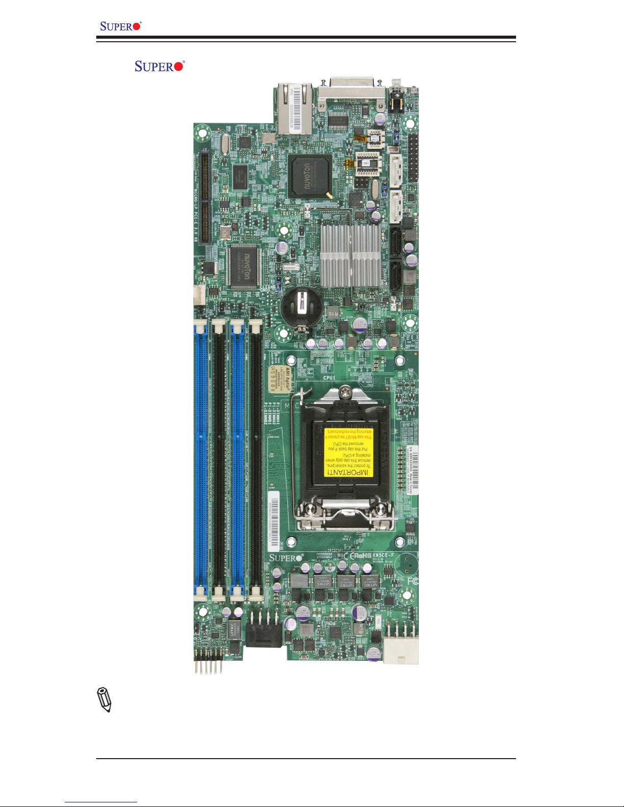
X9SCE-F Image
Note: All graphics and images shown in this manual were based upon the latest
PCB Revision available at the time of publishing of the manual. The motherboard
you've received may or may not look exactly the same as the image shown in
this manual.
Page 11
Chapter 1: Introduction
1-3
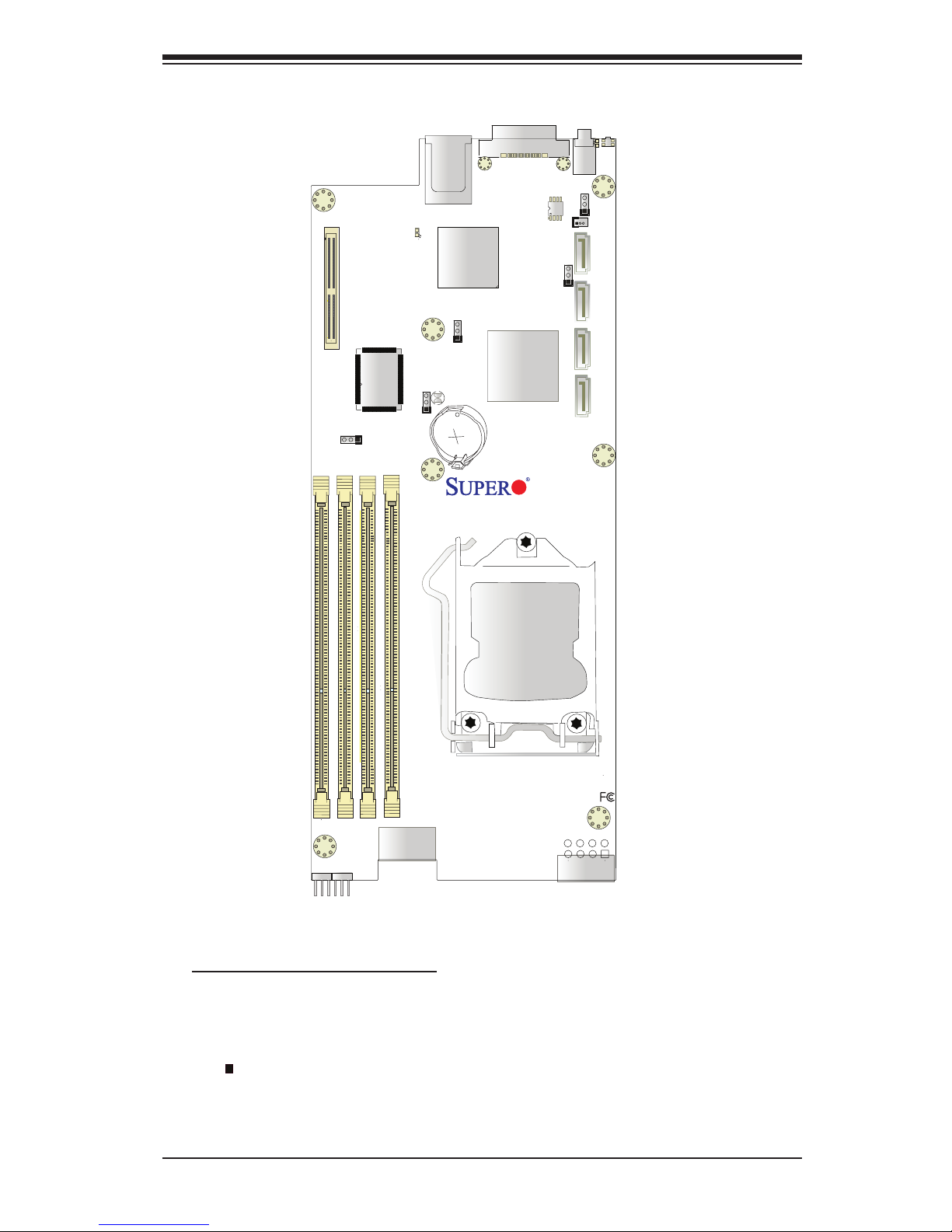
Motherboard Layout
Important Notes to the User
•Jumpers/Components not indicated are for testing only. See Chapter 2 for
detailed information on jumpers, I/O ports and JF1 front panel connections.
•" " indicates the location of "Pin 1".
•This motherboard supports up to 12 nodes/trays; each node/tray supports four
2.5" or two 3.5" HDDs.
JP18
JP17
JPWR2
I-SATA1
I-SATA3
J4
JKVM1
JPB1
JPG1
JWD1
JPME1
JPME2
JSD1
JBT1
HEARTBEAT LED
UID LED
MICRO-LP PCI-E 3.0 X8
X9SCE-F
PWR
P1-DIMMB2
P1-DIMMB1
P1-DIMMA2
P1-DIMMA1
CPU1
LED4
BIOS
JP16
UID SW
I-SATA2
I-SATA0
SW
8
Rev. 1.0a
Page 12
1-4
X9SCE-F User’s Manual
JP18
JP17
JPWR2
I-SATA1
I-SATA3
J4
JKVM1
JPB1
JPG1
JWD1
JPME1
JPME2
JSD1
JBT1
HEARTBEAT LED
UID LED
MICRO-LP PCI-E 3.0 X8
X9SCE-F
PWR
P1-DIMMB2
P1-DIMMB1
P1-DIMMA2
P1-DIMMA1
CPU1
LED4
BIOS
JP16
UID SW
I-SATA2
I-SATA0
SW
8
Rev. 1.0a
1
2
4
5
6
7
8
3
9
10
11
12
13
14
15
16
17
18
19
20
21
22
23
DIMMB2
DIMMA2
DIMMA1
DIMMB1
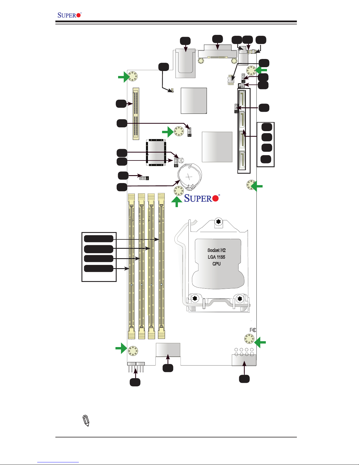
Note: DIMMA1-DIMMB2 memory slots only support very low prole unbuf-
fered (VLP UDIMM) memory modules.
See Note below.
Socket H2
LGA 1155
CPU
Page 13
Chapter 1: Introduction
1-5
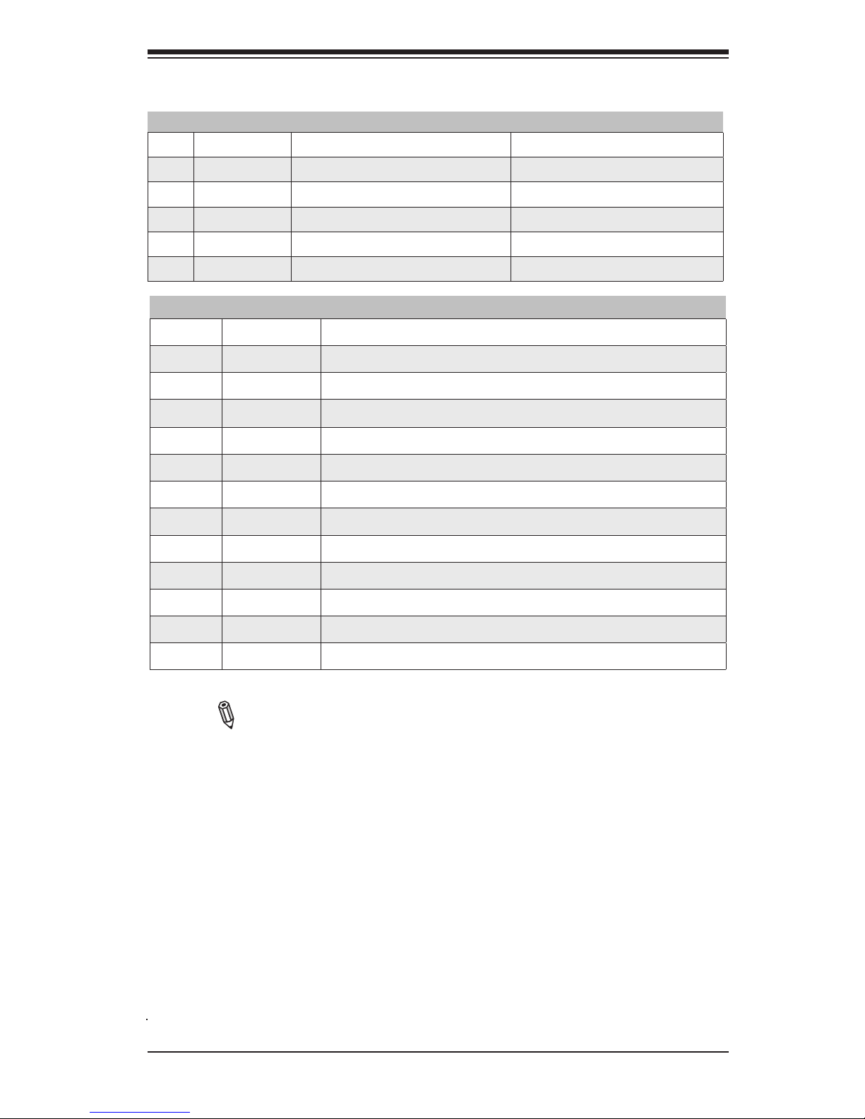
1/2 UID SW/LED Unit Identier Switch and LED Indicator
3 PWR SW/LED Power Switch and PWR LED
4 JKVM1 Keyboard, Video, Mouse Backpanel Connector
5 IPMI_LAN RJ45 IPMI Port
6 LED4 IPMI Status (Heartbeat)
7 MICRO-LP PCI-E 3.0/2.0 x8 Micro LP (Low Prole) Slot
12 BT1 On-board Battery
13 JP17, JP18
Motherboard Interface to PDB
14 JP16 Power Output for Hard Disk Drive (12V and 5V)
15 JPWR2 Power Connector from PDB
16~19 I-SATA3,2,1,0 I-SATA Ports. I-SATA0/1 supports SATA 3.0 (6Gb/s)
21 JSD1 Disk-On-Module (DOM) Power Connector
23 BIOS BIOS Chip
Note: This motherboard supports up to 12 nodes/trays; each node/tray
supports four (4) 2.5" or two (2) 3.5" disk drives.
Jumpers/Ports/Connectors
Jumpers
Connectors & LED Indicators
8 JPME2 ME Manufacturing Mode Pins 1-2 (Normal)
9 JBT1 CMOS Reset Short contact pads to reset CMOS
10 JWD1 Watch Dog Timer RST/NMI Selection Pins 1-2 (Reset)
11 JPME1 ME Recovery Mode Select Pins 1-2 (Normal)
20 JPG1 Onboard VGA Enable/Disable Pins 1-2 (Enabled)
22 JPB1 BMC Enable/Disable Pins 1-2 (Enabled)
Page 14
1-6
X9SCE-F User’s Manual
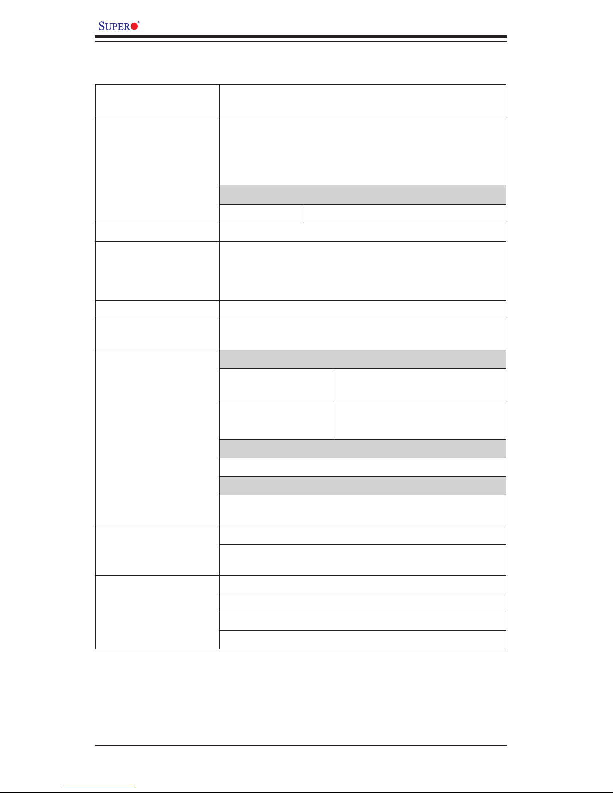
Motherboard Features
CPU Single Intel® Xeon E3-1200 & E3-1200 v. 2 series and 3rd
Gen. Core i3 CPU on an H2 socket (LGA 1155)
Memory Four (4) DIMM slots support up to 32 GB of Dual-Channel
Unbuffered ECC *1600/1333/1066 MHz DDR3 very low
prole (VLP) memory in 4 DIMM modules (*See the note
on Expansion Slots.)
DIMM sizes
DIMM 1 GB, 2 GB, 4 GB and 8GB
Chipset Intel® C204 PCH
Expansion Slots One (1) PCI-E Micro-LP (Low Prole) x 8 Slot
*BIOS Rev. 2.0 or above is required for support of new
E3-1200 v. 2 processors, which support PCI-E 3.0 & DDR3
1600 MHz memory.
Graphics One Video (KVM) Port supported by Matrix G200W
Network Connections One (1) Dual Channel RJ-45 Gigabit LAN IPMI Dedicated
LAN Port w/Activity LED
I/O Devices SATA/SAS Connections
SATA 2.0 Ports Two (2) SATA/SAS Ports from
SCU
SATA 3.0 Ports Two (2) (SATA 0/1)
(on IF Backpanel)
USB Devices
one (1) Internal Type A USB connector.
Serial Ports
One (1) COM port on the KVM (Keyboard/Video/Mouse)
connector
BIOS 8 MB SPI AMI BIOS® SM Flash BIOS
Play and Plug, ACPI 1.0/2.0/3.0, USB Keyboard, RTC
wakeup and SMBIOS 2.3 support
Power ACPI/ACPM Power Management
Main Switch Override Mechanism
One (1) Disk-On-Module (DOM) Power Connector (SATA)
Power-on mode for AC power recovery
Page 15

Chapter 1: Introduction
1-7
PC Health Monitoring CPU Monitoring
Onboard voltage monitors for CPU core,+1.8V, +3.3V,+5V,
+12V, +3.3V Stdby, +5V Stdby, VBAT, VCCP, Memory,
Chipset
Tachometer Monitoring
CPU Thermal Trip support
Thermal Monitor 2 (TM2) support
System Management PECI (Platform Environment Conguration Interface) 2.0
support
System resource alert via Supero Doctor III
SuperoDoctor III, Watch Dog
Unit ID LED, System/CPU overheat LED
CD Utilities BIOS ash upgrade utility
Drivers and software for Intel® C204 PCH chipset utilities
Other ROHS 6/6 (Full Compliance, Lead Free)
One (1) TPM Header
Dimensions 4.75" x 15.95"
Page 16
1-8
X9SCE-F User’s Manual
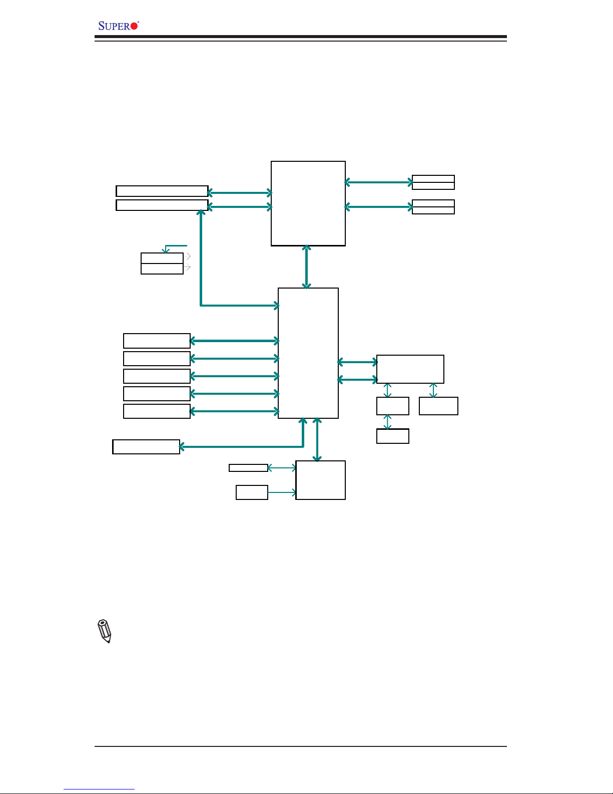
X9SCE-F Block Diagram
Note: This is a general block diagram. Please see the Motherboard Features pages
for details on the details of motherboard features.
Cougar Point
BLOCK DIAGRAM
DDR3 (CHA)
Sandy Bridge
PCIe2.0_x8
VRM 12
SVID
RoHS 6/6
PCIe x8 SLOT
DDR3 (CHB)
DIMM1
DIMM2(Far)
DIMM1
DIMM2(Far)
4 UDIMM
MISC VRs
1333/1066MHz
1333/1066MHz
5GT/s
x4 DMI II
5GT/s
P11-12
P29-30
LPC
RMII
VGA (KVM)
RTL8201
PHY
HERMON WPCM450
WINBOND
PCI32
RJ45
PCIe2.0_x8
PCIe x8 SLOT (Micro LP)
5GT/s
600MB/s
SATA-III
PCH
C204
2 SATA PORTS (BP)
300MB/s
SATA-II
1 SATA PORT (DOM)
3 USB PORTS
USB2.0
480Mbps
2 USB PORTS (KVM)
USB2.0
480Mbps
LPC
TPM1.2 Header
COM1(KVM)
LPC
HEALTH
INFO
LPC I/O
NCT6776F
FLASH
SPI 64Mb
SPI
PCIe2.0 x1
5GT/s
Page 17

Chapter 1: Introduction
1-9
1-2 Chipset Overview
The X9SCE-F supports a single Intel® Xeon E3-1200 series processor in an H2
Socket (LGA 1155). Built around the Intel C204 chipset, this motherboard provides
substantial enhancement to system performance and storage capability for entry-
level to mid-range blade servers in a microcloud platform.
The high-speed Direct Media Interface (DMI) featured in the Intel C204 chipset
supports high-speed Direct Media Interface (DMI) for chip-to-chip true isochronous
communication, providing up to 2 Gb/s of software-transparent data transfer rate
on each read/write direction. In addition, the X9SCE-F also features a TCO (Time
Controlled Operations) timer which allows the system to recover from a software/
hardware lock and perform tasks, including ECC Error Reporting, Function Dis-
able and Intruder Detect.
Intel C204 Express Chipset Features
•Direct Media Interface (up 4 Gb/s transfer, Full Duplex)
•Intel® Intel Rapid Storage Technology
•Intel I/O Virtualization (VT-d) Support
•Intel Trusted Execution Technology Support
•PCI Express 2.0 Interface (up to 5.0 GT/s)
•SATA Controller
•6 Gb/s on up to two ports
•3 Gb/s on all ports
•Advanced Host Controller Interface (AHCI)
Page 18

1-10
X9SCE-F User’s Manual
1-3 PC Health Monitoring
This section describes the PC health monitoring features of the X9SCE-F. The
motherboard has an onboard System Hardware Monitor chip that supports PC
health monitoring.
Recovery from AC Power Loss
BIOS provides a setting for you to determine how the system will respond when
AC power is lost and then restored to the system. You can choose for the system
to remain powered off (in which case you must hit the power switch to turn it back
on) or for it to automatically return to a power on state. See the Power Lost Control
setting in the BIOS chapter of this manual to change this setting. The default set-
ting is Last State.
Onboard Voltage Monitoring
The onboard voltage monitor will scan the following voltages continuously: CPU
core, +1.8V, +3.3V,+5V, +12V, +3.3V Stdby, +5V Stdby, VBAT, VCCP, Memory,
Chipset. Once a voltage becomes unstable, it will give a warning or send an error
message to the screen. The User can adjust the voltage thresholds to dene the
sensitivity of the voltage monitor by using SD III.
Fan Status Monitor with Software
The PC health monitor can check the RPM status of the cooling fans via Supero
Doctor III.
BIOS Support for USB Keyboard
If the USB keyboard is the only keyboard in the system, it will function like a normal
keyboard during system boot-up.
1-4 Power Supply
As with all computer products, a stable power source is necessary for proper and
reliable operation. It is even more important for processors that have high CPU
clock rates of 1 GHz and faster.
The X9SCE-F accommodates the SMC 1620W power supply through the
PDB and SATA back plane.
Page 19

Chapter 1: Introduction
1-11
1-5 Super I/O
The Super I/O provides one high-speed, 16550 compatible serial communication
ports (UARTs). This UART includes a 16-byte send/receive FIFO, a programmable
baud rate generator, complete modem control capability and a processor interrupt
system. It also provides legacy speed with baud rate of up to 115.2 Kbps as well
as an advanced speed with baud rates of 250 K, 500 K, or 1 Mb/s, which support
higher speed modems.
The Super I/O provides functions that comply with ACPI (Advanced Conguration
and Power Interface), which includes support of legacy and ACPI power manage-
ment through a SMI or SCI function pin. It also features auto power management
to reduce power consumption.
Page 20

1-12
X9SCE-F User’s Manual
Notes
Page 21
Chapter 2: Installation
2-1
Chapter 2
Installation
2-1 Standardized Warning Statements
The following statements are industry-standard warnings, provided to warn the user
of situations which have the potential for bodily injury. Should you have questions or
experience difculty, contact Supermicro's Technical Support department for assis-
tance. Only certied technicians should attempt to install or congure components.
Read this section in its entirety before installing or conguring components in the
Supermicro chassis.
Battery Handling
Warnung
Bei Einsetzen einer falschen Batterie besteht Explosionsgefahr. Ersetzen Sie die
Batterie nur durch den gleichen oder vom Hersteller empfohlenen Batterietyp.
Entsorgen Sie die benutzten Batterien nach den Anweisungen des Herstellers.
Warning!
There is a danger of explosion if the battery is replaced incorrectly. Replace the
battery only with the same or equivalent type recommended by the manufacturer.
Dispose of used batteries according to the manufacturer's instructions
電池の取り扱い
電池交換が正しく行われなかった場合、破裂の危険性があります。 交換する電池はメー
カーが推奨する型、または同等のものを使用下さい。 使用済電池は製造元の指示に従
って処分して下さい。
警告
电池更换不当会有爆炸危险。请只使用同类电池或制造商推荐的功能相当的电池更
换原有电池。请按制造商的说明处理废旧电池。
警告
電池更換不當會有爆炸危險。請使用製造商建議之相同或功能相當的電池更換原有
電池。請按照製造商的說明指示處理廢棄舊電池。
Page 22
2-2
X9SCE-F User’s Manual
Attention
Danger d'explosion si la pile n'est pas remplacée correctement. Ne la remplacer
que par une pile de type semblable ou équivalent, recommandée par le fabricant.
Jeter les piles usagées conformément aux instructions du fabricant.
¡Advertencia!
Existe peligro de explosión si la batería se reemplaza de manera incorrecta. Re-
emplazar la batería exclusivamente con el mismo tipo o el equivalente recomen-
dado por el fabricante. Desechar las baterías gastadas según las instrucciones
del fabricante.
경고!
배터리가 올바르게 교체되지 않으면 폭발의 위험이 있습니다. 기존 배터리와 동일
하거나 제조사에서 권장하는 동등한 종류의 배터리로만 교체해야 합니다. 제조사
의 안내에 따라 사용된 배터리를 처리하여 주십시오.
Waarschuwing
Er is ontplofngsgevaar indien de batterij verkeerd vervangen wordt. Vervang de
batterij slechts met hetzelfde of een equivalent type die door de fabrikant aan-
bevolen wordt. Gebruikte batterijen dienen overeenkomstig fabrieksvoorschriften
afgevoerd te worden.
Page 23

Chapter 2: Installation
2-3
Product Disposal
Warning!
Ultimate disposal of this product should be handled according to all national laws
and regulations.
製品の廃棄
この製品を廃棄処分する場合、国の関係する全ての法律・条例に従い処理する必要が
ありま す。
警告
本产品的废弃处理应根据所有国家的法律和规章进行。
警告
本產品的廢棄處理應根據所有國家的法律和規章進行。
Warnung
Die Entsorgung dieses Produkts sollte gemäß allen Bestimmungen und Gesetzen
des Landes erfolgen.
¡Advertencia!
Al deshacerse por completo de este producto debe seguir todas las leyes y regla-
mentos nacionales.
Attention
La mise au rebut ou le recyclage de ce produit sont généralement soumis à des
lois et/ou directives de respect de l'environnement. Renseignez-vous auprès de
l'organisme compétent.
Page 24

2-4
X9SCE-F User’s Manual
2-2 Static-Sensitive Devices
Electrostatic-Discharge (ESD) can damage electronic com ponents. To prevent dam-
age to your system board, it is important to handle it very carefully. The following
measures are generally sufcient to protect your equipment from ESD.
Precautions
• Use a grounded wrist strap designed to prevent static discharge.
• Touch a grounded metal object before removing the board from the antistatic
bag.
• Handle the board by its edges only; do not touch its components, peripheral
chips, memory modules or gold contacts.
• When handling chips or modules, avoid touching their pins.
• Put the motherboard and peripherals back into their antistatic bags when not in
use.
• For grounding purposes, make sure that your computer chassis provides excel-
lent conductivity between the power supply, the case, the mounting fasteners
and the motherboard.
• Use only the correct type of onboard CMOS battery. Do not install the onboard
upside down battery to avoid damaging the components.
Unpacking
The motherboard is shipped in antistatic packaging to avoid static damage. When
unpacking the board, make sure the person handling it is static protected.
Waarschuwing
De uiteindelijke verwijdering van dit product dient te geschieden in overeenstemming
met alle nationale wetten en reglementen.
경고!
이 제품은 해당 국가의 관련 법규 및 규정에 따라 폐기되어야 합니다.
Page 25
Chapter 2: Installation
2-5
JP18
JP17
JPWR2
I-SATA1
I-SATA3
J4
JKVM1
JPB1
JPG1
JWD1
JPME1
JPME2
JSD1
JBT1
HEARTBEAT LED
UID LED
MICRO-LP PCI-E 3.0 X8
X9SCE-F
PWR
P1-DIMMB2
P1-DIMMB1
P1-DIMMA2
P1-DIMMA1
CPU1
LED4
BIOS
JP16
UID SW
I-SATA2
I-SATA0
SW
8
Rev. 1.0a
2-3 Motherboard Installation
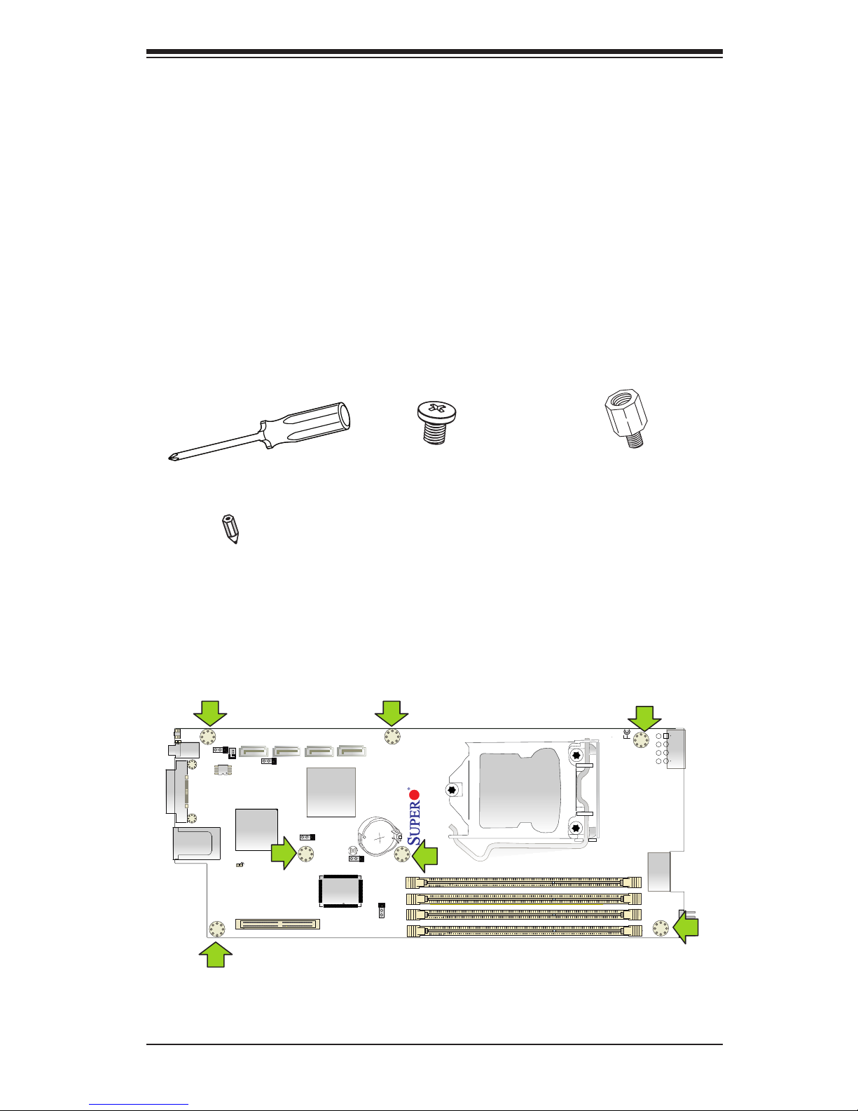
All motherboards have standard mounting holes to t a blade-type chassis. Make
sure that the locations of all the mounting holes for both motherboard and chassis
match. Although a chassis may have both plastic and metal mounting fasteners,
metal ones are highly recommended because they ground the motherboard to the
chassis. Make sure that the metal standoffs click in or are screwed in tightly. Then
use a screwdriver to secure the motherboard onto the motherboard tray.
Caution: Some components are very close to the mounting holes. Please take pre-
cautionary measures to prevent damage to these components when installing the
motherboard to the chassis.
Tools Needed
Philips Screwdriver
Pan head screws (7 pieces)
Location of Mounting Holes
There are seven (7) mounting holes on the X9SCE-F motherboard. These holes
correspond to screw holes in a matching motherboard tray that slides into a blade-
type chassis. Please refer to the illustrations on the next page for a typical blade
chassis installation.
Standoffs (7 pieces)
(Only if needed)
Note: The above items are not provided with this motherboard.
Image rotated 90
◦
Page 26
2-6
X9SCE-F User’s Manual
Installation Instructions
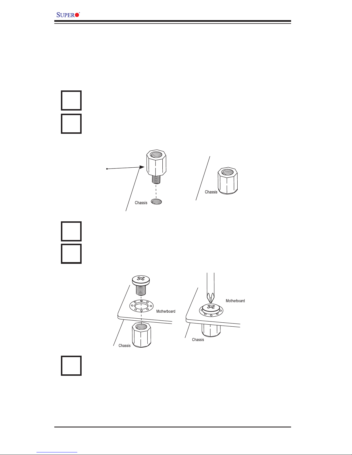
Caution: To avoid damaging the motherboard and its components, please do not use
a force greater than 8 lb/inch on each mounting screw during motherboard installation.
Locate the mounting holes on the motherboard. Refer to the layout on the
previous page for mounting hole locations.
Locate the matching mounting holes on the motherboard mounting tray.
Install standoffs needed. Align the mounting holes on the motherboard
against the mounting holes on the motherboard tray.
Install the motherboard carefully to avoid damaging motherboard compo-
nents.
Insert a Pan head #6 screw into a mounting hole on the motherboard and
its matching mounting hole on the chassis, using the Philips screwdriver.
Repeat Step 4 to insert #6 screws to all mounting holes.
1
2
3
Stand Off
4
5
Page 27
Chapter 2: Installation
2-7
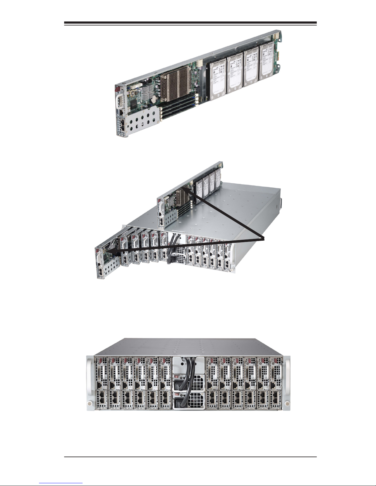
The X9SCE-F board
The image above shows the X9SCE-F motherboard mounted on a tray to be
installed in the Supermicro CSE-939H-R1K63B 3U chassis.
The image above shows the the X9SCE-F motherboard mounted on a tray and the
way it is installed as one of the nodes in a server chassis.
The image above shows the server chassis with 12 nodes.
Page 28
2-8
X9SCE-F User’s Manual
JP18
JP17
JPWR2
I-SATA1
I-SATA3
J4
JKVM1
JPB1
JPG1
JWD1
JPME1
JPME2
JSD1
JBT1
HEARTBEAT LED
UID LED
MICRO-LP PCI-E 3.0 X8
X9SCE-F
PWR
P1-DIMMB2
P1-DIMMB1
P1-DIMMA2
P1-DIMMA1
CPU1
LED4
BIOS
JP16
UID SW
I-SATA2
I-SATA0
SW
8
Rev. 1.0a
Installing and Removing DIMMs
2-4 System Memory
CAUTION
Exercise extreme care when installing or removing DIMM
modules to prevent any possible damage.
How to Install DDR3 DIMMs
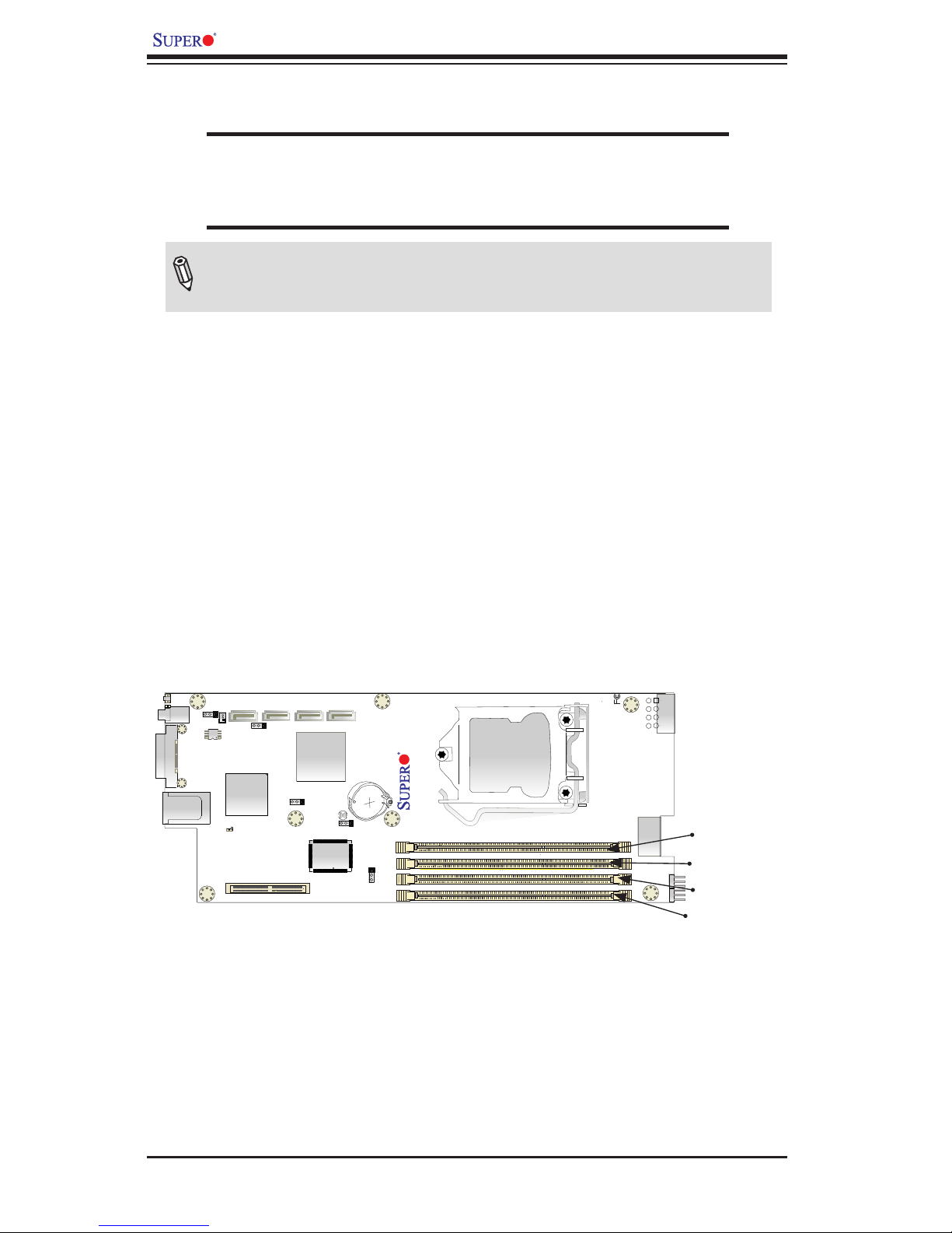
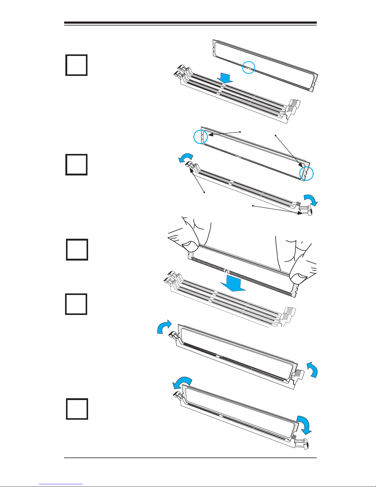
1. Insert the desired number of DIMMs into the memory slots, starting with
DIMMA2, then DIMMB2, then DIMMA1, DIMMB1. Pay attention to the notch
along the bottom of the module to prevent incorrect DIMM module installation.
2. Insert each DIMM module vertically and snap it into place. Repeat step 1 to
install more memory, if needed. See instructions on the next page.
Memory Support
This motherboard supports up to 32GB of Unbuffered ECC DDR3 1066/1333/1600*
MHz VLP (Very Low Prole) memory in 4 DIMM slots. (*BIOS rev. 2.0 is needed
for support of new E3-1200 v2 CPUs, which support PCI-E 3.0 and DDR3 1600
MHz memory.)
Note: Check the Supermicro website for a list of memory modules that
have been validated with the X9SCE-F motherboard.
DIMMA1
DIMMB1
Image rotated 90
◦
DIMMA2
DIMMB2
Page 29
Chapter 2: Installation
2-9
Insert the DIMM module vertically and press
down until the module
snaps into place.
To Remove:
Use your thumbs to
gently push the Lock/
Release tabs near both
ends of the module. This should
release it from the slot. Pull the
DIMM module upwards.
Installing and Removing DIMMs
Position the DIMM
module's bottom key
so that it aligns with
the receptive point on the slot.
When the module is
properlly inserted, the
Lock/Release tabs will
automatically secure
the DIMM module, locking it
into place.
Push a Lock/Release tab
to the Release position.
Make sure that the side
notches of the DIMM
module aligns with the Lock/
Release tab of the slot as it is
pressed in.
Lock/Release Tabs
Notches
Release
Release
Lock
Lock
1
2
3
4
Release
Release
5
Press Down
Page 30
2-10
X9SCE-F User’s Manual
Memory Population Guidelines
Notes:
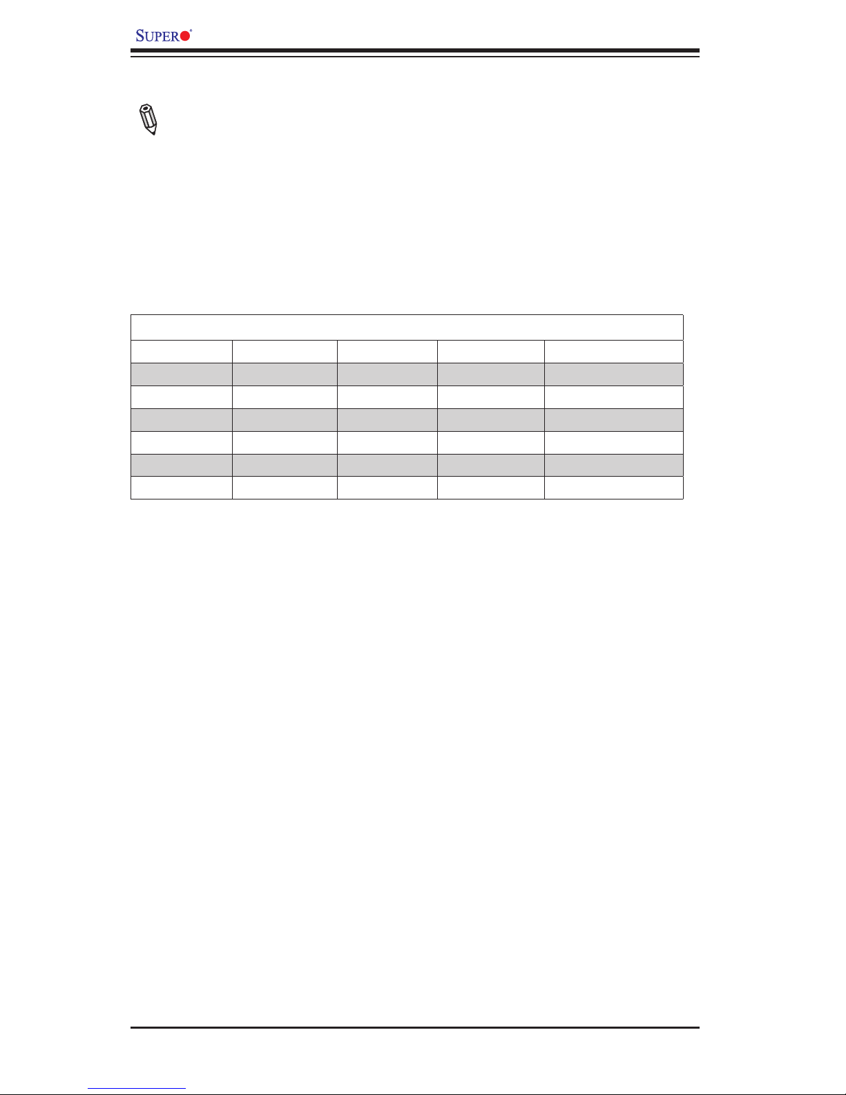
1. When installing memory modules, the DIMM slots should be populated in the
following order: DIMMA2, DIMMB2, DIMMA1 and DIMMB1.
2. Always use DDR3 DIMM modules of the same size, type and speed.
3. The motherboard will support one DIMM module or three DIMM modules
installed. For best memory performance, install DIMM modules in pairs.
Recommended Population (Balanced)
DIMMA2 DIMMB2 DIMMA1 DIMMB1 Total System Memory
2GB DIMM 2GB DIMM 4GB
2GB DIMM 2GB DIMM 2GB DIMM 2GB DIMM 8GB
4GB DIMM 4GB DIMM 8GB
4GB DIMM 4GB DIMM 4GB DIMM 4GB DIMM 16GB
8GB DIMM 8GB DIMM 16GB
8GB DIMM 8GB DIMM 8GB DIMM 8GB DIMM 32GB
Page 31
Chapter 2: Installation
2-11
I/OPortLocationsandDenitions
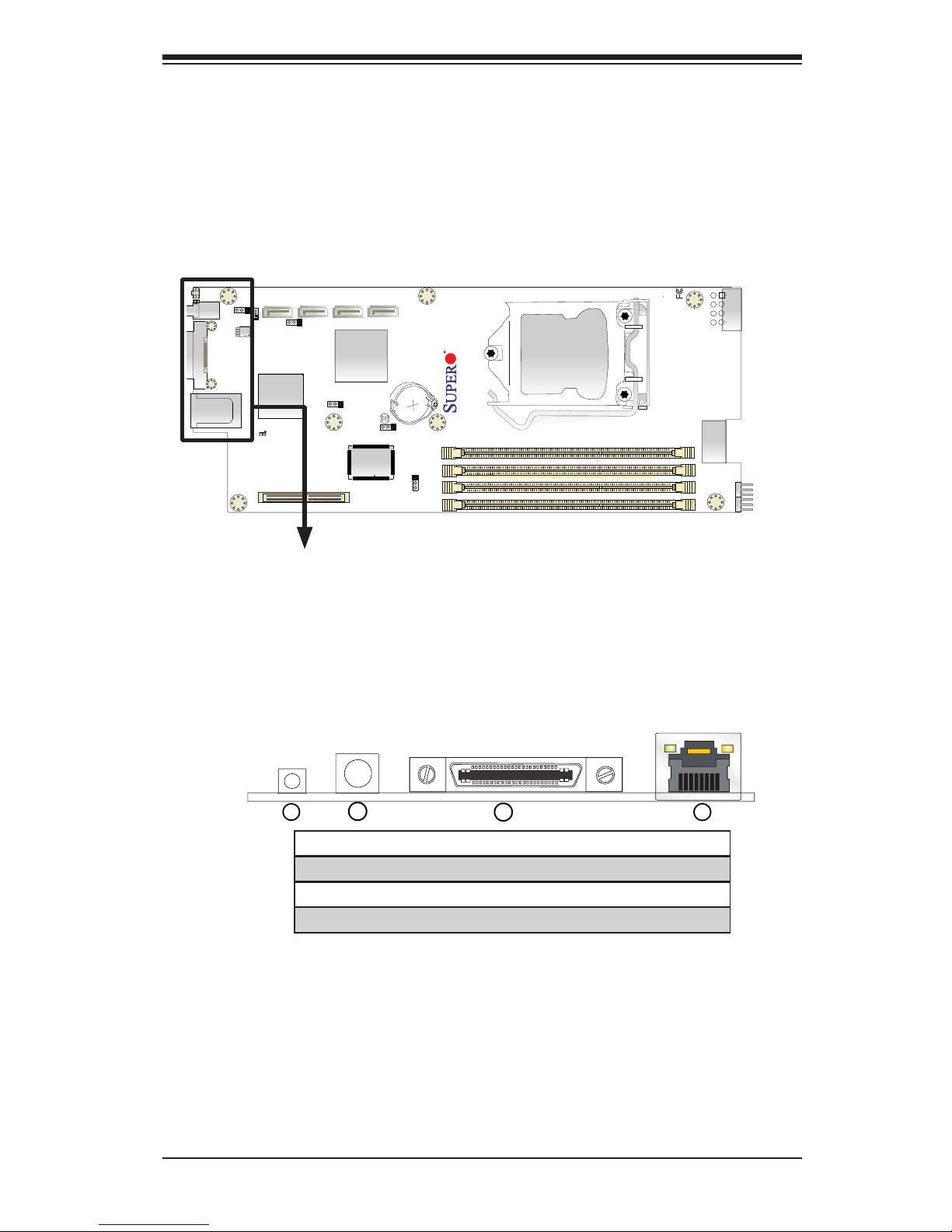
2-5 Connectors/I/O Ports
The I/O ports are color coded in conformance with the PC 99 specication. See the
gure below for the colors and locations of the various I/O ports.
Back Panel Connectors and I/O Ports
2
4
1
3
1. UID Button and LED
2. Power Button and LED
3. KVM (Keyboard/Video/Mouse) via Serial Port
4. IPMI_LAN Port
Back Panel Connectors
JP18
JP17
JPWR2
I-SATA1
I-SATA3
J4
JKVM1
JPB1
JPG1
JWD1
JPME1
JPME2
JSD1
JBT1
HEARTBEAT LED
UID LED
MICRO-LP PCI-E 3.0 X8
X9SCE-F
PWR
P1-DIMMB2
P1-DIMMB1
P1-DIMMA2
P1-DIMMA1
CPU1
LED4
BIOS
JP16
UID SW
I-SATA2
I-SATA0
SW
8
Rev. 1.0a
Image rotated 90
◦
Page 32
2-12
X9SCE-F User’s Manual
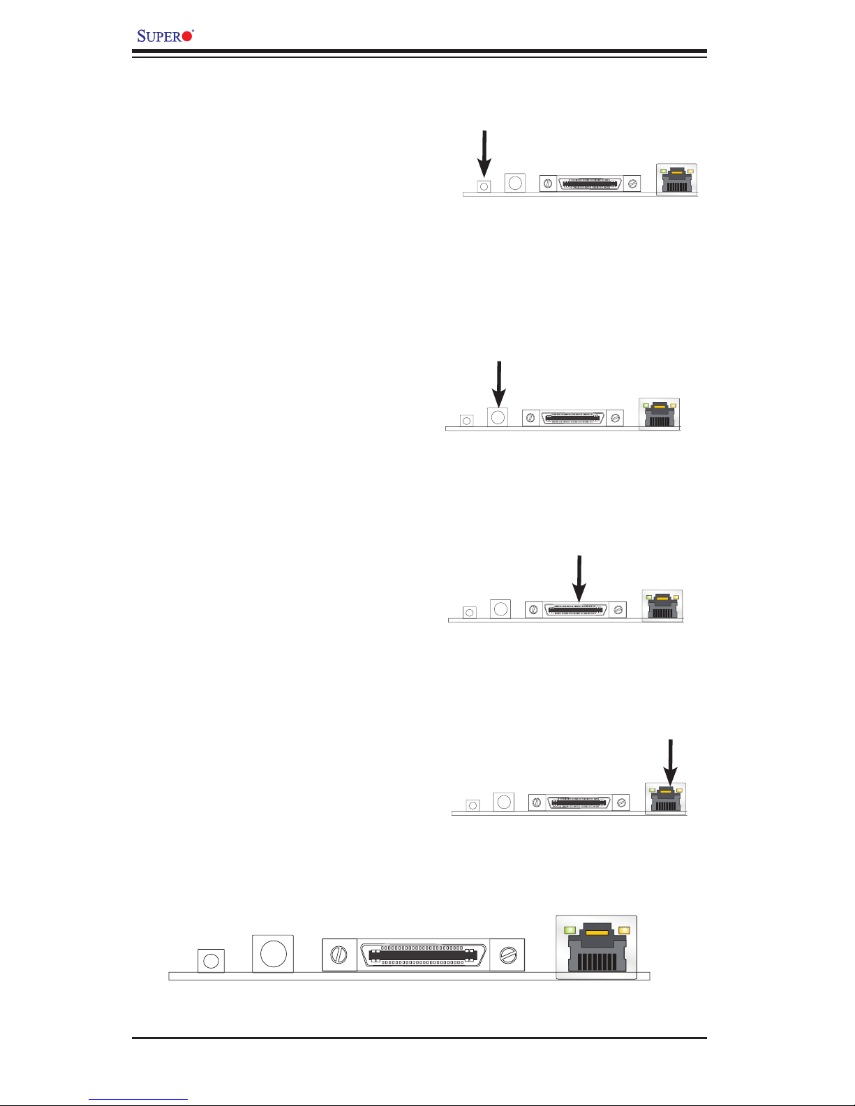
Back Panel Connectors
KVM Port
The KVM port (JKVM) supports key-
board, VGA, mouse via UART interface.
Please attach a compatible KVM connec-
tor/switch to this port.
IPMI_LAN Port
A dedicated IPMI_LAN port is located
next to the KVM port to provide dedi-
cated network connection for IPMI 2.0.
This port accepts RJ45 type cables.
Power Button & LED
A Power Button and LED is located next
to the IPMI_LAN port. Push this button to
turn on the motherboard. When the LED
is on, the power of this motherboard is
turned on.
UID Button/LED Indicator
The Unit ID (UID) Button is used in con-
junction with the UID switch in front of the
chassis, and the UID LED located next to
it. When the switch is turned on, the UID
LED will turn on to indicate the unit that
might be in need of service.
Page 33
Chapter 2: Installation
2-13
JP18
JP17
JPWR2
I-SATA1
I-SATA3
J4
JKVM1
JPB1
JPG1
JWD1
JPME1
JPME2
JSD1
JBT1
HEARTBEAT LED
UID LED
MICRO-LP PCI-E 3.0 X8
X9SCE-F
PWR
P1-DIMMB2
P1-DIMMB1
P1-DIMMA2
P1-DIMMA1
CPU1
LED4
BIOS
JP16
UID SW
I-SATA2
I-SATA0
SW
8
Rev. 1.0a
2-6 Connecting Cables
This section provides brief descriptions and pin-out denitions for onboard connec-
tors or headers. Be sure to use the correct cable for each header or connector.
IF + POWER
This edge connector, located on the opposite end of the motherboard from the I/O
back panel, is used to connect the motherboard to the back plane of the server
chassis. Through this connector, the motherboard receives its power and commu-
nicates with other components installed in the system.
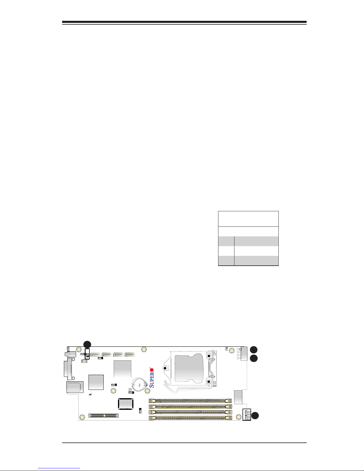
IF + Power
SATA DOM Power
A
B
Image rotated 90
◦
A
SATA DOM Power
The SATA DOM Power header on JSD1
is used to supply power to SATA Disk-
on-Module (DOM) solid-state storage
devices. See the table on the right for
pin denitions.
DOM PWR
PinDenitions
Pin# Denition
1 +5V
2 Ground
3 Ground
B
Page 34
2-14
X9SCE-F User’s Manual
2-7 Jumper Settings
Explanation of Jumpers
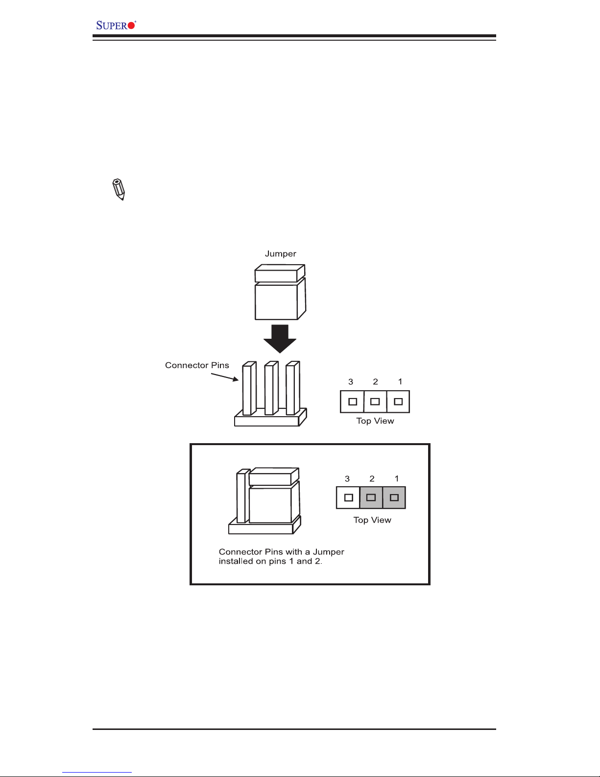
To modify the operation of the motherboard, jumpers can be used to choose between
optional settings. Jumpers create shorts between two pins to change the function
of the connector. Pin 1 is identied with a square solder pad on the printed circuit
board.
Note: On two pin jumpers, "Closed" means the jumper is on and "Open" means
the jumper is off the pins.
Page 35
Chapter 2: Installation
2-15
JP18
JP17
JPWR2
I-SATA1
I-SATA3
J4
JKVM1
JPB1
JPG1
JWD1
JPME1
JPME2
JSD1
JBT1
HEARTBEAT LED
UID LED
MICRO-LP PCI-E 3.0 X8
X9SCE-F
PWR
P1-DIMMB2
P1-DIMMB1
P1-DIMMA2
P1-DIMMA1
CPU1
LED4
BIOS
JP16
UID SW
I-SATA2
I-SATA0
SW
8
Rev. 1.0a
CMOS Clear (JBT1)
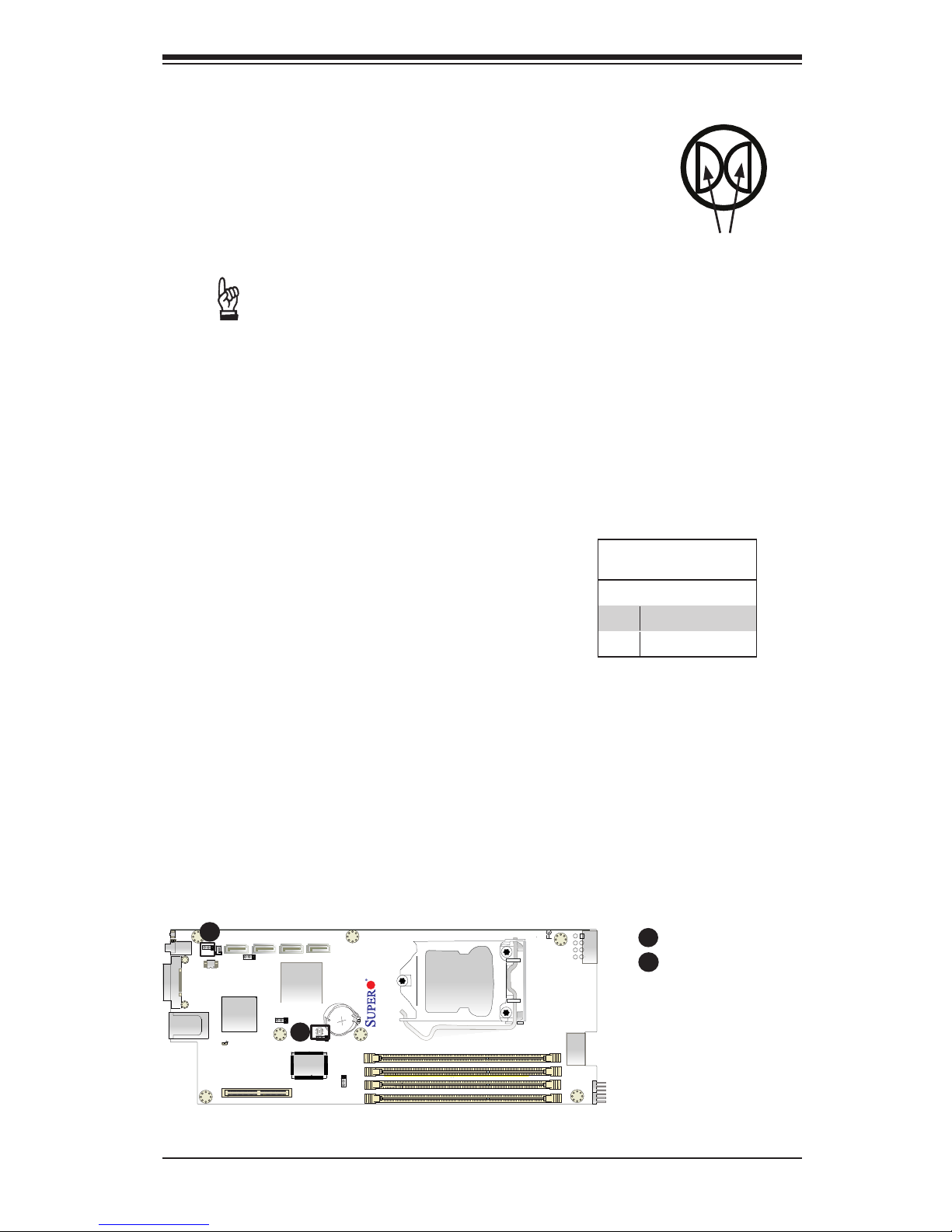
JBT1 is used to clear CMOS. Instead of pins, this "jumper"
consists of contact pads to prevent accidental clearing of
CMOS. To clear CMOS, use a metal object such as a small
screwdriver to touch both pads at the same time to short the
connection. Always remove the AC power cord from the sys-
tem before clearing CMOS.
Important: You must completely shut down the
system, remove the AC power cord, and then short
JBT1 to clear CMOS. Clearing CMOS will also clear
all passwords.
A
CMOS Clear
BMC Enable/Disable
Metal contact pads
B
Image rotated 90
◦
A
BMC Enable/Disable (JPB1)
Jumper JPB1 allows you to enable the embed-
ded BMC (Baseboard Management) Control-
ler to provide IPMI 2.0/KVM support on the
motherboard. See the table on the right for
jumper settings..
BMC Enable
Jumper Settings
Pin# Denition
1-2 Enabled (default)
2-3 Disabled
B
Page 36
2-16
X9SCE-F User’s Manual
JP18
JP17
JPWR2
I-SATA1
I-SATA3
J4
JKVM1
JPB1
JPG1
JWD1
JPME1
JPME2
JSD1
JBT1
HEARTBEAT LED
UID LED
MICRO-LP PCI-E 3.0 X8
X9SCE-F
PWR
P1-DIMMB2
P1-DIMMB1
P1-DIMMA2
P1-DIMMA1
CPU1
LED4
BIOS
JP16
UID SW
I-SATA2
I-SATA0
SW
8
Rev. 1.0a
VGA Enable
Watch Dog Enable
A
B
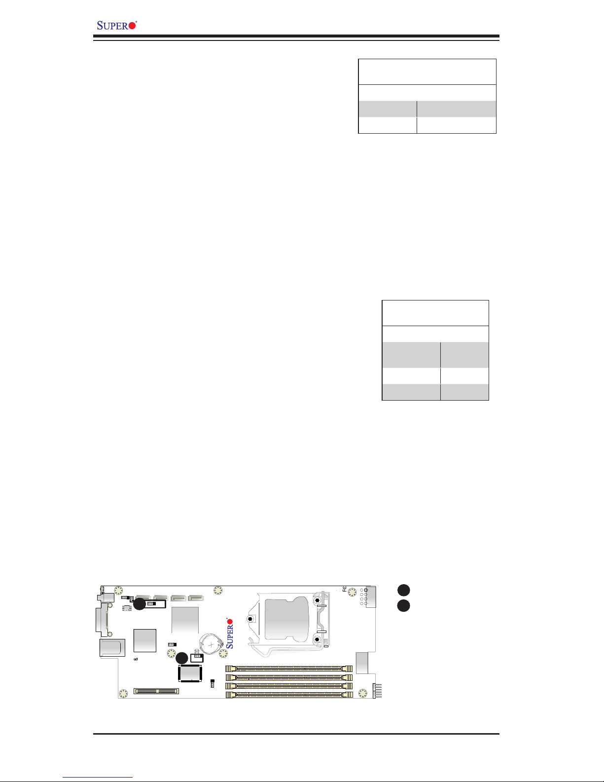
VGA Enable (JPG1)
JPG1 allows the user to enable the onboard
VGA connector (through the KVM port). Close
Pins 1/2 to use this function. The default set-
ting is Enabled.
VGA Enable/Disable Jumper Set-
tings (JPG1)
Both Jumpers Denition
Pins 1-2 Enabled (Default)
Pins 2-3 Disabled
Watch Dog RST/NMI Selection (JWD1)
Watch Dog (JWD1) is a system monitor that
can reboot the system when a software ap-
plication hangs. Close pins 1/2 to reset the
system if an application hangs. Close pins 2/3
to generate a non-maskable interrupt signal for
the application that hangs. See the table on the
right for jumper settings. Watch Dog must also
be enabled in the BIOS.
Watch Dog
Jumper Settings
Jumper Setting Denition
Pins 1-2 Reset
(default)
Pins 2-3 NMI
Open Disabled
B
Image rotated 90
◦
A
Page 37
Chapter 2: Installation
2-17
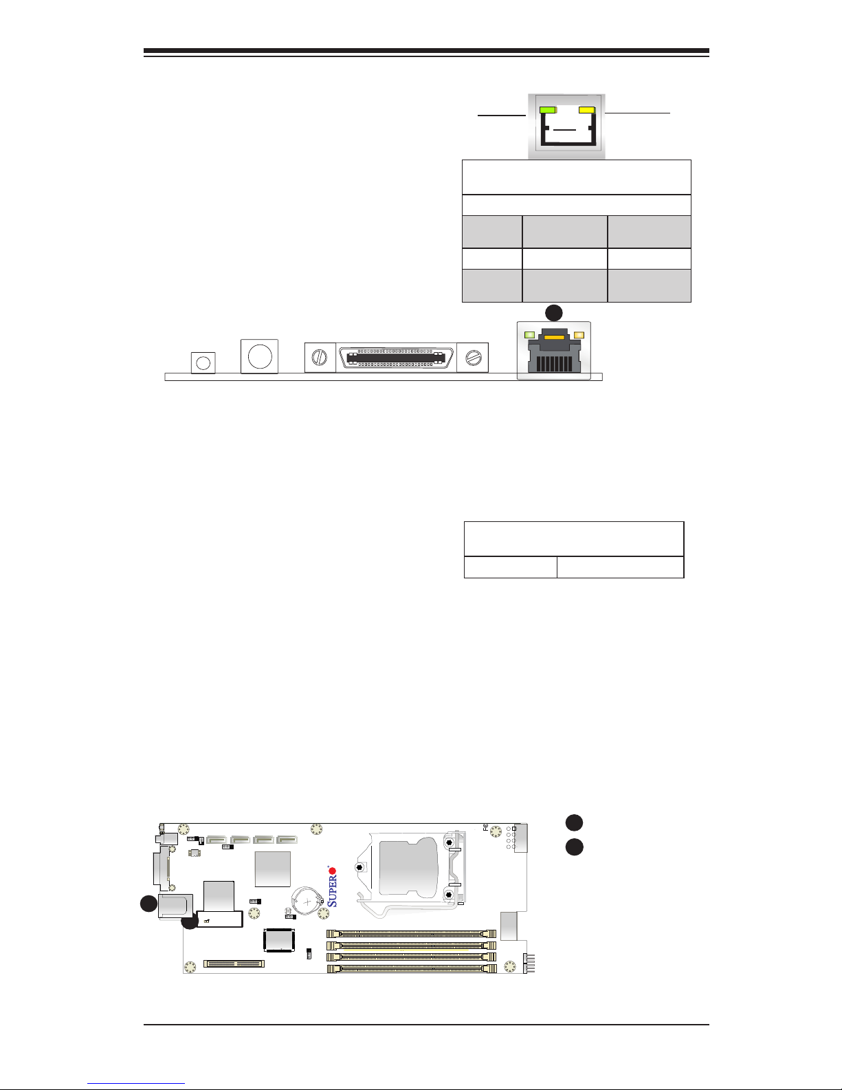
2-8 Onboard Indicators
IPMI LAN Port
Back Panel Connectors
A
A
IPMI Dedicated LAN Port
An IPMI Dedicated LAN port is installed
on the I/O back panel. The yellow LED
on the right indicates activity, while
the green LED on the left indicates
the speed of the connection. See the
tables at right for more information.
Activity LED
Link LED
IPMI
Image rotated 90
◦
A
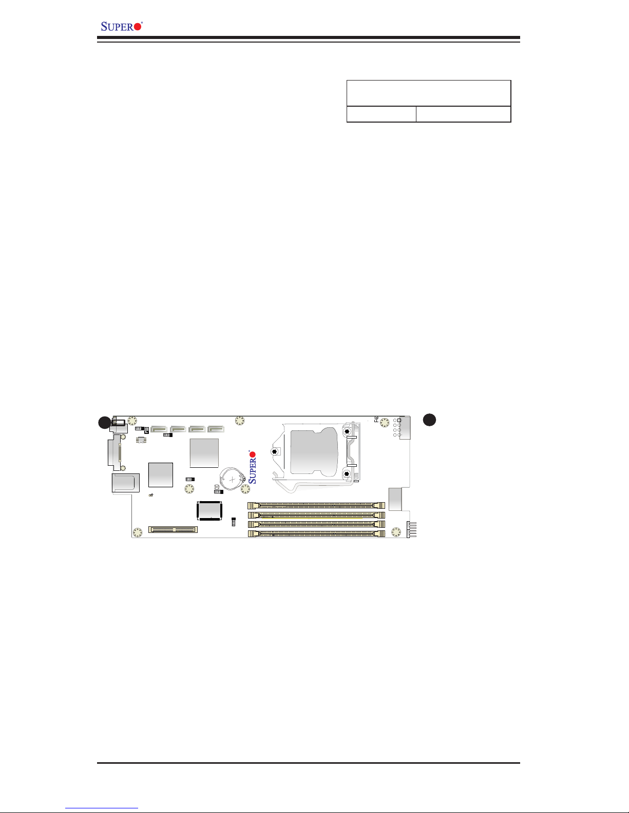
IPMI Heartbeat LED
An IPMI Heartbeat LED is located at
LED4. When LED4 blinks, the IPMI
functions properly. Refer to the table
on the right for details. Also see the
layout below for the LED location.
IPMI Heartbeat LED Indicator (LED4)
LED State
Blinking IPMI is ready for use
IPMI LAN Link Speed LED (Left) &
Connection Activity LED (Right)
LED Color/State Denition
Off Off No Connection
or 10 Mbps
Activity Amber: Blinking Active
Speed Green: Solid On100 Mbps
B
B
IPMI Heartbeat LED
JP18
JP17
JPWR2
I-SATA1
I-SATA3
J4
JKVM1
JPB1
JPG1
JWD1
JPME1
JPME2
JSD1
JBT1
HEARTBEAT LED
UID LED
MICRO-LP PCI-E 3.0 X8
X9SCE-F
PWR
P1-DIMMB2
P1-DIMMB1
P1-DIMMA2
P1-DIMMA1
CPU1
LED4
BIOS
JP16
UID SW
I-SATA2
I-SATA0
SW
8
Rev. 1.0a
Page 38
2-18
X9SCE-F User’s Manual
JP18
JP17
JPWR2
I-SATA1
I-SATA3
J4
JKVM1
JPB1
JPG1
JWD1
JPME1
JPME2
JSD1
JBT1
HEARTBEAT LED
UID LED
MICRO-LP PCI-E 3.0 X8
X9SCE-F
PWR
P1-DIMMB2
P1-DIMMB1
P1-DIMMA2
P1-DIMMA1
CPU1
LED4
BIOS
JP16
UID SW
I-SATA2
I-SATA0
SW
8
Rev. 1.0a
Image rotated 90
◦
A
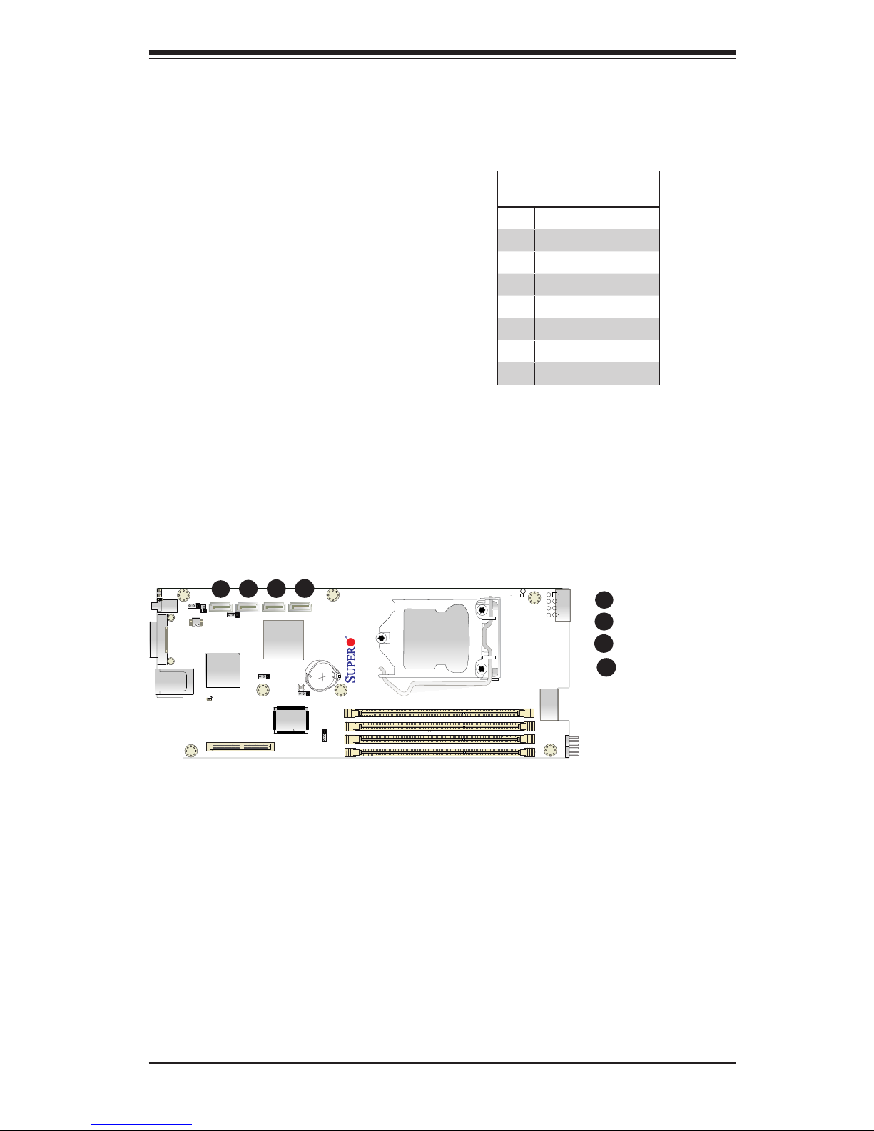
Unit ID LED
The Unit LED is controlled by the Unit ID
Button. It indicates a unit that may be in
need of service. Turn on the UID button in
the front of the chassis or on the mother-
board's I/O panel to identify the failed unit.
Unit ID LED
LED Status
On (Steady) Unit ID switch is on
Unit ID LED
A
Page 39
Chapter 2: Installation
2-19
JP18
JP17
JPWR2
I-SATA1
I-SATA3
J4
JKVM1
JPB1
JPG1
JWD1
JPME1
JPME2
JSD1
JBT1
HEARTBEAT LED
UID LED
MICRO-LP PCI-E 3.0 X8
X9SCE-F
PWR
P1-DIMMB2
P1-DIMMB1
P1-DIMMA2
P1-DIMMA1
CPU1
LED4
BIOS
JP16
UID SW
I-SATA2
I-SATA0
SW
8
Rev. 1.0a
C
2-9 SATA Connections
Note the following conditions when connecting the SATA cables:
I-SATA 0
I-SATA 1
I-SATA 2
I-SATA 3
A
B
C
A
B
SATA Connections (SATA4)
Four Serial ATA (SATA) (I-SATA 0-3)
connectors are located on the mother-
board. I-SATA0/1 supports SATA 3.0,
and I-SATA2/3 supports SATA 2.0.
These Serial Link connections provide
faster data transmission than legacy
Parallel ATA. See the table on the right
for pin denitions.
SATA Connectors
PinDenitions
Pin# Signal
1 Ground
2 SATA_TXP
3 SATA_TXN
4 Ground
5 SATA_RXN
6 SATA_RXP
7 Ground
Image rotated 90
◦
D
D
Page 40

2-20
X9SCE-F User’s Manual
Notes
Page 41

3-1
Chapter 3: Troubleshooting
Chapter 3
Troubleshooting
3-1 Troubleshooting Procedures
Use the following procedures to troubleshoot your system. If you have followed all
of the procedures below and still need assistance, refer to the ‘Technical Support
Procedures’ and/or ‘Returning Merchandise for Service’ section(s) in this chapter.
Always disconnect the AC power cord before adding, changing or installing any
hardware components.
Before Power On
1. Be sure to unplug the power cable before installing or removing the compo-
nents.)
2. Make sure that there are no short circuits between the motherboard and chas-
sis.
3. Disconnect all ribbon/wire cables from the motherboard, including those for the
keyboard and mouse. Also, be sure to remove all add-on cards.
No Power
1. Make sure that there are no short circuits between the motherboard and chas-
sis.
2. Make sure that all jumpers are set to their default positions.
3. Check if the 115V/230V switch on the power supply is properly set.
4. Turn the power switch on and off to test the system.
5. The battery on your motherboard may be old. Check to make sure that it still
supplies ~3VDC. If it does not, replace it with a new one.
No Video
1. If the power is on, but you have no video-in this case, you will need to remove
all the add-on cards and cables rst.
2. Remove all memory modules and turn on the system.
Page 42

3-2
X9SCE-F User’s Manual
Memory Errors
1. Make sure that all DIMM modules are properly installed and fully seated in
the slots.
2. Please check Section 2-4 and make sure that you are using the correct memory.
Also, it is recommended that you use the memory modules of the same type
and speed for all DIMMs in the system.
3. Check for bad DIMM modules or slots by swapping modules between slots to
see if you can locate the faulty modules.
4. Check the power supply voltage 115V/230V switch.
IfYouLosetheSystem’sSetupConguration
1. Please be sure to use a high quality power supply. A poor quality power supply
may cause the system to lose the CMOS setup information. Refer to Section
1-5 for details on recommended power supplies.
2. The battery on your motherboard may be old. Check to verify that it still supplies
~3VDC. If it does not, replace it with a new one.
3. If the above steps do not x the Setup Conguration problem, contact your
vendor for repairs.
3-2 Technical Support Procedures
Before contacting Technical Support, please make sure that you have followed all
the steps listed below. Also, note that as a motherboard manufacturer, Supermicro
does not sell directly to end users, so it is best to rst check with your distributor or
reseller for troubleshooting services. They should know of any possible problem(s)
with the specic system conguration that was sold to you.
1. Please go through the ‘Troubleshooting Procedures’ and 'Frequently Asked
Question' (FAQ) sections in this chapter or see the FAQs on our website
(http://www.supermicro.com/support/faqs/) before contacting Technical Sup-
port.
2. BIOS upgrades can be downloaded from our website at (http://www.supermicro.
com/support/bios/).
Note: Not all BIOS can be ashed. Some cannot be ashed; it depends
on the modications to the boot block code.
3. If you've followed the instructions above to troubleshoot your system, and still
cannot resolve the problem, then contact Supermicro's technical support and
provide them with the following information:
Page 43

3-3
Chapter 3: Troubleshooting
• Motherboard model and PCB revision number
• BIOS release date/version (this can be seen on the initial display when your
system rst boots up)
• System conguration (OS version, peripheral devices, power supply type, etc)
An example of a Technical Support form is on our website at (http://www.
supermicro.com/support/contact.cfm).
4. Distributors: For immediate assistance, please have your account number ready
when placing a call to our technical support department. We can be reached
by e-mail at [email protected], by phone at: (408) 503-8000, option
2, or by fax at (408)503-8019.
3-3 Frequently Asked Questions
Question: What type of memory does my motherboard support?
Answer:
The X9SCE-F supports up to 32GB of unbuffered ECC DDR3 1066/1333/1600
MHz, two-way interleaved or non-interleaved Very Low Prole (VLP) DIMM
memory. See Section 2-5 for details on installing memory.
Question: Why does Microsoft Windows show less memory than what is
physically installed?
Answer: Microsoft implemented a design change in Windows XP with Service
Pack 2 (SP2) and Windows Vista. This change is specic to the Physical Ad-
dress Extension (PAE) mode behavior which improves driver compatibility. For
more information, please read the following article at Microsoft’s Knowledge
Base website at: http://support.microsoft.com/kb/888137.
Question: How do I update my BIOS?
Answer: It is recommended that you do not upgrade your BIOS if you are not
experiencing any problems with your system. Updated BIOS les are located
on our web site at http://www.supermicro.com/support/bios/. Please check our
BIOS warning message and the information on how to update your BIOS on our
website. Select your motherboard model and download the BIOS (.rom) le to
your computer. Also, check the current BIOS revision and make sure that it is
newer than your BIOS before downloading. You may choose the zip le or the
.exe le. If you choose the zipped BIOS le, please unzip the BIOS le onto a
bootable device or a USB pen/thumb drive. To ash the BIOS, run the batch
Page 44

3-4
X9SCE-F User’s Manual
le named "ami.bat" with the new BIOS ROM le from your bootable device or
USB pen/thumb drive. Use the following format:
F:\> ami.bat BIOS-ROM-lename.xxx <Enter>
Notes: Always use the le named “ami.bat” to update the BIOS and insert
a space between "ami.bat" and the lename. The BIOS-ROM-lename
will bear the motherboard name (i.e., X9SCD) and build version as the
extension. For example, "X9SCD0.526".
When completed, your system will automatically reboot. If you choose the .exe
le, please run the .exe le under Windows to create the BIOS ash oppy disk.
Insert the oppy disk into the system you wish to ash the BIOS. Then, boot
the system to the oppy disk. The BIOS utility will automatically ash the BIOS
without any prompts. Please note that this process may take a few minutes
to complete. Do not be concerned if the screen is paused for a few minutes.
Warning: Do not shut down or reset the system while updating the BIOS to prevent
possible system boot failure!
When the BIOS ashing screen is completed, the system will reboot and will
show “Press F1 or F2”. At this point, you will need to load the BIOS defaults.
Press <F1> to go to the BIOS setup screen, and press <F9> to load the default
settings. Next, press <F10> to save and exit. The system will then reboot.
Note: The SPI BIOS chip installed on this motherboard is not removable.
To repair or replace a damaged BIOS chip, please send your motherboard
to RMA at Supermicro for service.
If your BIOS crashes and your motherboard will no longer boot, please read Ap-
pendix C - UEFI BIOS Recovery Instructions for instructions.
Question: What's on the CD that came with my motherboard?
Answer: The supplied compact disc has quite a few drivers and programs
that will greatly enhance your system. We recommend that you review the CD
and install the applications you need. Applications on the CD include chipset
drivers for Windows, security and audio drivers.
Page 45
3-5
Chapter 3: Troubleshooting
Proper Battery Disposal
Warning! Please handle used batteries carefully. Do not damage the battery in any
way; a damaged battery may release hazardous materials into the environment. Do
not discard a used battery in the garbage or a public landll. Please comply with the
regulations set up by your local hazardous waste management agency to dispose of
your used battery properly.
Battery Installation
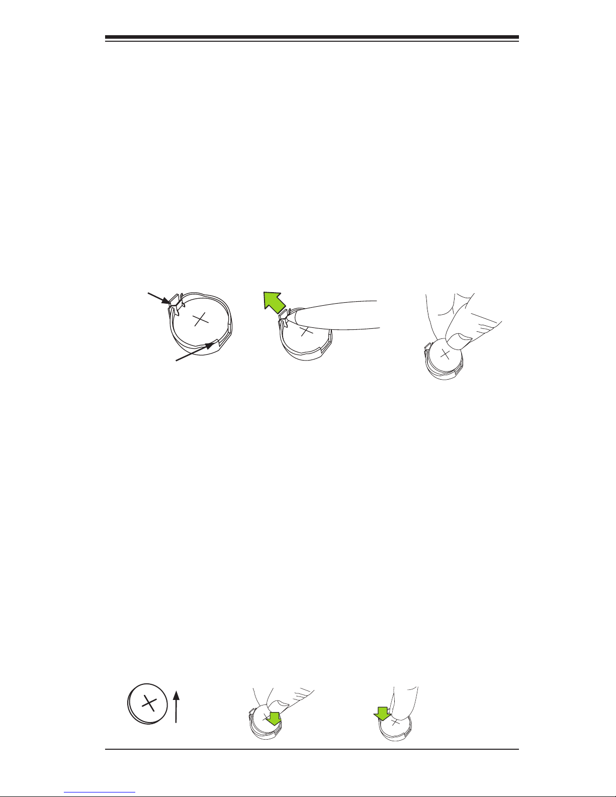
1. To install an onboard battery, follow the steps 1& 2 above and continue
below:
2. Identify the battery's polarity. The positive (+) side should be facing up.
3. Insert the battery into the battery holder and push it down until you hear a
click to ensure that the battery is securely locked.
Warning: When replacing a battery, be sure to only replace it with the same type.
Battery
Lock
Battery
Battery Holder
1
2
This side up
Press down until
you hear a click.
3-4 Battery Removal and Installation
Battery Removal
To remove the onboard battery, follow the steps below:
1. Power off your system and unplug your power cable.
2. Locate the onboard battery as shown below.
3. Using a tool such as a pen or a small screwdriver, push the battery lock out-
wards to unlock it. Once unlocked, the battery will pop out from the holder.
4. Remove the battery.
Page 46

3-6
X9SCE-F User’s Manual
3-5 Returning Merchandise for Service
A receipt or copy of your invoice marked with the date of purchase is required
before any warranty service will be rendered. You can obtain service by calling
your vendor for a Returned Merchandise Authorization (RMA) number. When
returning to the manufacturer, the RMA number should be prominently displayed
on the outside of the shipping carton, and mailed prepaid or hand-carried. Ship-
ping and handling charges will be applied for all orders that must be mailed when
service is complete.
This warranty only covers normal consumer use and does not cover damages
incurred in shipping or from failure due to the alteration, misuse, abuse or improper
maintenance of products.
During the warranty period, contact your distributor rst for any product prob-
lems.
Page 47

Chapter 4: AMI BIOS
4-1
Chapter 4
BIOS
4-1 Introduction
This chapter describes the AMI BIOS Setup Utility for the X9SCE-F motherboard.
The AMI ROM BIOS is stored in a Flash EEPROM and can be easily updated. This
chapter describes the basic navigation of the AMI BIOS Setup Utility setup screens.
Note: For instructions on BIOS recovery, please refer to the instruction
guide posted at http://www.supermicro.com/support/manuals/.
Starting BIOS Setup Utility
To enter the AMI BIOS Setup Utility screens, press the <Delete> key while the
system is booting up.
Note: In most cases, the <Delete> key is used to invoke the AMI BIOS
setup screen. There are a few cases when other keys are used, such as
<F1>, <F2>, etc.
Each main BIOS menu option is described in this manual. The Main BIOS setup
menu screen has two main frames. The left frame displays all the options that can
be congured. Grayed-out options cannot be congured. Options in blue can be
congured by the user. The right frame displays the key legend. Above the key
legend is an area reserved for a text message. When an option is selected in the
left frame, it is highlighted in white. Often a text message will accompany it. (Note:
the AMI BIOS has default text messages built in. Supermicro retains the option to
include, omit, or change any of these text messages.)
The AMI BIOS Setup Utility uses a key-based navigation system called "hot keys".
Most of the AMI BIOS setup utility "hot keys" can be used at any time during the
setup navigation process. These keys include <F1>, <F10>, <Enter>, <ESC>, ar-
row keys, etc.
Note: Options printed in Bold are default settings.
HowToChangetheCongurationData
The conguration data that determines the system parameters may be changed by
entering the AMI BIOS Setup utility. This Setup utility can be accessed by pressing
<Del> at the appropriate time during system boot.
Page 48
4-2
X9SCE-F User’s Manual
How to Start the Setup Utility
Normally, the only visible Power-On Self-Test (POST) routine is the memory test.
As the memory is being tested, press the <Delete> key to enter the main menu of
the AMI BIOS Setup Utility. From the main menu, you can access the other setup
screens. An AMI BIOS identication string is displayed at the left bottom corner of
the screen, below the copyright message.
Warning! Do not upgrade the BIOS unless your system has a BIOS-related issue.
Flashing the wrong BIOS can cause irreparable damage to the system. In no event
shall Supermicro be liable for direct, indirect, special, incidental, or consequential dam-
ages arising from a BIOS update. If you have to update the BIOS, do not shut down
or reset the system while the BIOS is updating. This is to avoid possible boot failure.
4-2 Main Setup
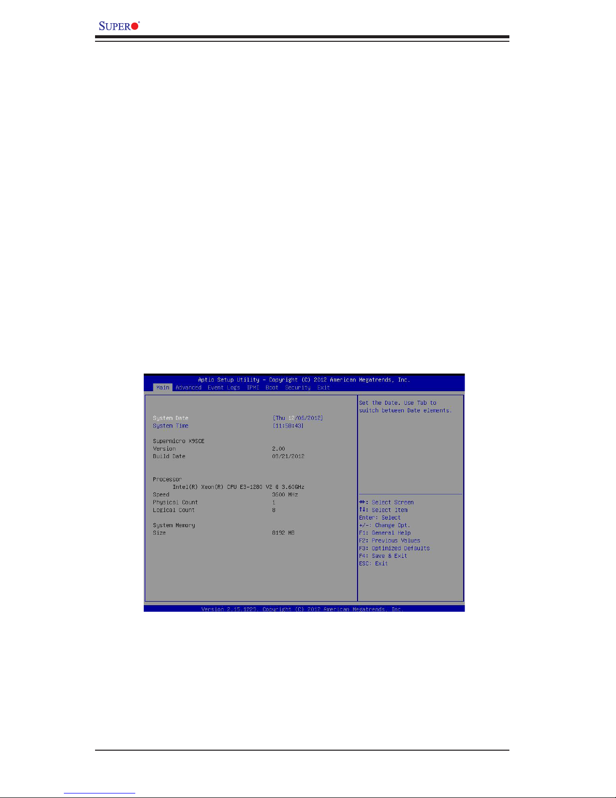
When you rst enter the AMI BIOS Setup Utility, you will enter the Main setup screen.
You can always return to the Main setup screen by selecting the Main tab on the
top of the screen. The Main BIOS Setup screen is shown below.
Page 49

Chapter 4: AMI BIOS
4-3
System Overview: The following BIOS information will be displayed:
System Time/System Date
Use this option to change the system time and date. Highlight System Time or Sys-
tem Date using the arrow keys. Enter new values through the keyboard. Press the
<Tab> key or the arrow keys to move between elds. The date must be entered in
Day MM/DD/YY format. The time is entered in HH:MM:SS format. (Note: The time
is in the 24-hour format. For example, 5:30 P.M. appears as 17:30:00.)
Supermicro X9SCE
Version
Build Date
Processor
The AMI BIOS will automatically display the status of processor as shown below:
Processor
Speed
Physical Count
Logical Count
System Memory
This displays the size of memory available in the system:
Size
Page 50
4-4
X9SCE-F User’s Manual
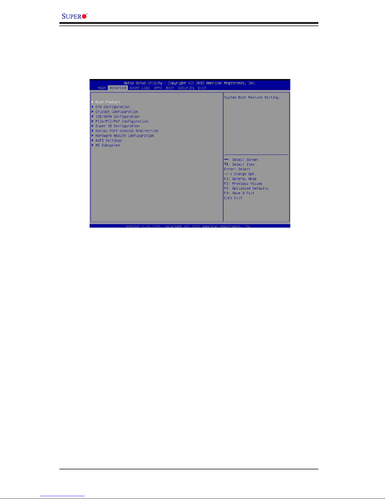
4-3 AdvancedSetupCongurations
Use the arrow keys to select Boot Setup and hit <Enter> to access the submenu
items:
Boot Feature
Quiet Boot
This feature allows the user to select the bootup screen display between POST
messages and the OEM logo. Select Disabled to display the POST messages.
Select Enabled to display the OEM logo instead of the normal POST messages.
The options are Enabled and Disabled.
AddOn ROM Display Mode
This feature sets the display mode for Option ROM. The options are Force BIOS
and Keep Current.
Bootup Num-Lock
This feature selects the Power-on state for Numlock key. The options are Off
and On.
Wait For 'F1' If Error
Select Enabled to force the system to wait until the 'F1' key is pressed if an error
occurs. The options are Disabled and Enabled.
Page 51

Chapter 4: AMI BIOS
4-5
INT19 Trap Response
Interrupt 19 is the software interrupt that handles the boot disk function. When this
item is set to Immediate, the ROM BIOS of the host adaptors will "trap" Interrupt
19 immediately and allow the drives that are attached to these host adaptors to
function as bootable disks. If this item is set to Postponed, the ROM BIOS of the
host adaptors will execute the trap during legacy boot only. The options are Im-
mediate and Postponed.
Watch Dog Function
If enabled, the Watch Dog timer will allow the system to automatically reboot when
a non-recoverable error occurs that lasts for more than ve minutes. The options
are Enabled and Disabled.
Power Button Function
This feature controls how the system shuts down when the power button is pressed.
Select 4-Second Override to force the user to press and hold the Power Button for
4 seconds before the system turns off. Select Instant Off if you want the system to
instantly power off when the Power Button is pressed. The options are 4 Second
Override and Instant Off.
Restore on AC Power Loss
Use this feature to set the power state after a power outage. Select Power-Off for
the system power to remain off after a power loss. Select Power-On for the system
power to be turned on after a power loss. Select Last State to allow the system
to resume its last state before a power loss. The options are Power-On, Stay-Off
and Last State.
CPUConguration
Note: Take Caution when changing the Advanced settings. An incorrect
value may cause system to become unstable. When this occurs, revert
to the default setting.
Clock Spread Spectrum
Select Enabled to allow BIOS to monitor and attempt to reduce the level of Elec-
tromagnetic Interference caused by the components whenever needed. Select
Disabled to enhance system stability. The options are Disabled and Enabled.
Intel® Hyper Threading Technology
Set to Enabled to use the processor's Hyper Threading Technology feature. The
options are Enabled and Disabled.
Page 52

4-6
X9SCE-F User’s Manual
Active Processor Cores
Set to Enabled to use a processor's Second Core and beyond. (Please refer to
Intel's web site for more information.) The options are All, 1, 2 and 3.
Execute-Disable Bit Capability (Available when supported by the OS and
the CPU)
Set to Enabled to enable the Execute Disable Bit which will allow the processor
to designate areas in the system memory where an application code can execute
and where it cannot, thus preventing a worm or a virus from ooding illegal codes
to overwhelm the processor or damage the system during an attack. The default is
Enabled. (Refer to Intel and Microsoft Web Sites for more information.)
Intel® Virtualization Technology (Available when supported by the CPU)
Select Enabled to use the feature of Virtualization Technology to allow one platform
to run multiple operating systems and applications in independent partitions, creat-
ing multiple "virtual" systems in one physical computer. The options are Enabled
and Disabled. Note: If there is any change to this setting, you will need to power
off and restart the system for the change to take effect. Please refer to Intel’s web
site for detailed information.
Hardware Prefetcher (Available when supported by the CPU)
If set to Enabled, the hardware prefetcher will prefetch streams of data and instruc-
tions from the main memory to the L2 cache in the forward or backward manner to
improve CPU performance. The options are Disabled and Enabled.
Adjacent Cache Line Prefetch (Available when supported by the CPU)
The CPU fetches the cache line for 64 bytes if this option is set to Disabled. The
CPU fetches both cache lines for 128 bytes as comprised if Enabled.
Intel® AES-NI
Set to Enabled to use the processor's Advanced Encryption Standard (AES) feature.
The options are Enabled and Disabled.
Power Technology
This feature determines what power-saving scheme the motherboard uses. The
options are Disabled, Energy Efcient and Custom. If Custom is selected, the
following options become available:
EIST (Available when Power Technology is set to Custom)
EIST (Enhanced Intel SpeedStep Technology) allows the system to automati-
cally adjust processor voltage and core frequency in an effort to reduce
Page 53

Chapter 4: AMI BIOS
4-7
power consumption and heat dissipation. Please refer to Intel’s web site
for detailed information. The options are Disabled and Enabled.
CPU C3 Report (Available when Power Technology is set to Custom)
Select Enabled to allow the BIOS to report the CPU C3 State (ACPI C2) to
the operating system. During the CPU C3 State, the CPU clock generator
is turned off. The options are Enabled and Disabled.
CPU C6 Report (Available when Power Technology is set to Custom)
Select Enabled to allow the BIOS to report the CPU C6 State (ACPI C3) to
the operating system. During the CPU C6 State, the power to all cache is
turned off. The options are Enabled and Disabled.
CPU C7 Report (Available when Power Technology is set to Custom)
Select Enabled to allow the BIOS to report the CPU C7 State (ACPI C3) to
the operating system. CPU C7 State is a processor-specic low C-State.
The options are Enabled and Disabled.
C1E Support (Available when Power Technology is set to Custom)
Select Enabled to enable Enhanced C1 Power State to boost system per-
formance. The options are Enabled and Disabled.
Turbo Boost Technology (Available if Intel® EIST
technology is Enabled)
Turbo Mode
This feature allows processor cores to run faster than marked frequency in
specic conditions. The options are Disabled and Enabled.
Long duration power limit - this is the processor power consumption limit
(in Watts) during a long duration time window.
Long duration maintained - this is the time in milliseconds where the Long
Duration Power Limit is maintained.
Short duration power limit - During Turbo Mode, the system may exceed
the processor's default power setting and exceed the Short Duration Power
limit. By increasing this value, the processor can provide better performance
for a short duration.
Page 54

4-8
X9SCE-F User’s Manual
ChipsetConguration
WARNING: Setting the wrong values in the following sections may cause the system
to malfunction.
CPUBridgeConguration
This item displays the current CPU Revision, Current CPU1 Memory Fre-
quency, Memory Type and Memory Reference Code Revision.
Memory Frequency
This feature allows the user to select the memory speed. Under normal
conditions, please set this to Auto. The options are Auto, Force DDR-
1066, Force DDR-1333, and Force DDR-1600.
IntegratedI/OConguration
This item displays the current North Bridge Revision.
Intel VT-d
Select Enabled to enable Intel's Virtualization Technology support for
Direct I/O VT-d by reporting the I/O device assignments to VMM through
the DMAR ACPI Tables. This feature offers fully-protected I/O resource-
sharing across the Intel platforms, providing the user with greater reliabil-
ity, security and availability in networking and data-sharing. The settings
are Enabled and Disabled.
Active State Power Management
Select Enabled to start Active-State Power Management for signal
transactions between L0 and L1 Links on the PCI Express Bus. This
maximizes power-saving and transaction speed. The options are Enabled
and Disabled.
PCIE Maximum Read Request
This feature selects the setting for the PCIE maximum read request size.
The options are Auto, 128 Bytes, 256 Bytes, 512 Bytes, 1024 Bytes,
2048 Bytes, and 4096 Bytes.
PCI Express Port
This feature enables or disables the PCI Express port. The options are
Disabled, Enabled and Auto.
Page 55

Chapter 4: AMI BIOS
4-9
PCI Express Port - Gen X
This feature enables or disables the PCI Express Gen X port. The options
are Disabled, Enabled and Auto.
De-emphasis Control
Use this feature to congure the de-emphasis control on PEG. The options
are -6 dB and -3.5 dB.
Detect Non-Compliance Device
This feature enables or disables the detection of a non-compliant device
that is attached to the PCI Express Graphics (PEG) port. The options are
Disabled, and Enabled.
SouthBridgeConguration
This item displays the current South Bridge Revision.
USB Functions
This feature allows the user to decide the number of onboard USB ports to
be enabled. The Options are Disabled and Enabled.
Legacy USB Support (available if USB Functions above is Enabled)
Select Enabled to use Legacy USB devices. If this item is set to Auto, Legacy
USB support will be automatically enabled if a legacy USB device is installed
on the motherboard, and vise versa. The settings are Disabled, Enabled
and Auto.
BIOS EHCI Hand-Off (available if USB Functions above is Enabled)
This item is for Operating Systems that does not support Enhanced Host
Controller Interface (EHCI) hand-off. When enabled, EHCI ownership change
will be claimed by the EHCI driver. The settings are Enabled and Disabled.
Port 60/64 Emulation (available if USB Functions above is Enabled)
Select Enabled to activate I/O port 60h/64h emulation support. This must be
enabled for complete USB keyboard legacy support for Operating Systems
that are not compatible with USB devices. The settings are Enabled and
Disabled.
Page 56

4-10
X9SCE-F User’s Manual
IDE/SATAConguration
When this submenu is selected, the AMI BIOS automatically detects the presence
of the IDE devices and displays the following items:
SATA Mode
This item selects the mode for the installed drives. The options are Disabled, IDE
Mode, AHCI Mode and RAID Mode.
IDE Mode
The following items are displayed when IDE Mode is selected:
IDE Legacy / Native Mode Selection
Use this feature to specify the operating mode of the integrated SATA
controllers. The options are Native and Legacy.
SATA Port0~Port5
This item displays the information detected on the installed SATA drives
on the particular SATA port.
AHCI Mode
The following items are displayed when AHCI Mode is selected:
Aggressive Link Power Management
When Enabled, the SATA AHCI controller manages the power usage of
the SATA link. The controller will put the link in a low power mode dur-
ing extended periods of I/O inactivity, and will return the link to an active
state when I/O activity resumes. The options are Enabled and Disabled.
SATA Port0~Port5
This item displays the information detected on the installed SATA drives
on the particular SATA port.
Hot Plug
Set this item to Enabled for hot-plugging support. The options are
Enabled and Disabled.
Staggered Spin Up
Set this item to Enabled for Staggered Spin-up support. The options
are Enabled and Disabled.
Page 57

Chapter 4: AMI BIOS
4-11
RAID Mode
The following items are displayed when RAID Mode is selected:
PCH RAID CodeBase
Select Intel to enable the Intel SATA Host RAID Utility. Select LSI to use
the LSI Host RAID Utility. The options are Intel and LSI.
SATA Port0~Port5
This item displays the information detected on the installed SATA drives
on the particular SATA port.
Hot Plug
Set this item to Enabled to enable hot-plugging. The options are
Enabled and Disabled.
PCIe/PCI/PnPConguration
This feature allows the user to set the PCI/PnP congurations for the following
items:
PCI Latency Timer
This feature sets the latency Timer of each PCI device installed on a PCI bus. Select
64 to set the PCI latency to 64 PCI clock cycles. The options are 32, 64, 96, 128,
160, 192, 224 and 248.
Above 4G Decoding (Available if the system supports 64-bit PCI decoding)
Select Enabled to decode a PCI device that supports 64-bit in the space above 4G
Address. The options are Enabled and Disabled.
PERR# Generation
Select Enabled to allow a PCI device to generate a PERR number for a PCI Bus
Signal Error Event. The options are Enabled and Disabled.
SERR# Generation
Select Enabled to allow a PCI device to generate an SERR number for a PCI Bus
Signal Error Event. The options are Enabled and Disabled.
Launch Storage OpROM Policy
Use this feature to select the Option ROM to boot the system when there are multiple
UEFI and Legacy storage Option ROMs available in the system. The options are
Do not launch, UEFI only, Legacy only, Legacyrst, and UEFI rst.
Page 58

4-12
X9SCE-F User’s Manual
SMC Riser Card on Micro-LP
Use this feature to select what riser card to use on the Micro-LP slot. The options
are No Riser and RSC-MLP-E8R.
Micro-LP PCI-E Slot OPROM
Use this feature to enable or disable the Micro-LP PCI-E slot OPROM option. The
options are Enabled and Disabled.
SuperIODeviceConguration
Serial Port 1
Select Enabled to enable the onboard serial port. The options are Enabled and
Disabled.
Serial Port 1 Settings
This option species the base I/O port address and the Interrupt Request address
of Serial Port 1. Select Auto to allow the serial port to automatically assign system
resources. The options for Serial Port 1 are Auto, (IO=3F8h; IRQ=4), (IO=3F8h;
IRQ=3, (IO=2F8h; IRQ=3), (IO=3E8h; IRQ=5), (IO=2E8h; IRQ=7).
Serial Port Console Redirection
COM 1, SOL
These two submenus allow the user to congure the following Console Redirection
settings for a COM Port specied by the user.
COM1, SOL Console Redirection
Select Enabled to use a COM Port selected by the user for Console Redirection.
The options are Enabled and Disabled. The default setting for COM1 is Disabled,
and for SOL is Enabled.
Console Redirection Settings
Terminal Type
This feature allows the user to select the target terminal emulation type for Con-
sole Redirection. Select VT100 to use the ASCII Character set. Select VT100+ to
add color and function key support. Select ANSI to use the Extended ASCII Char-
acter Set. Select VT-UTF8 to use UTF8 encoding to map Unicode characters
into one or more bytes. The options are ANSI, VT100, VT100+, and VT-UTF8.
Page 59

Chapter 4: AMI BIOS
4-13
Bits Per second
Use this feature to set the transmission speed for a serial port used in Console
Redirection. Make sure that the same speed is used in the host computer and the
client computer. A lower transmission speed may be required for long and busy
lines. The options are 9600, 19200, 38400, 57600 and 115200 (bits per second).
Data Bits
Use this feature to set the data transmission size for Console Redirection. The
options are 7 Bits and 8 Bits.
Parity
A parity bit can be sent along with regular data bits to detect data transmission
errors. Select Even if the parity bit is set to 0, and the number of 1's in data bits
is even. Select Odd if the parity bit is set to 0, and the number of 1's in data bits
is odd. Select None if you do not want to send a parity bit with your data bits
in transmission. Select Mark to add a mark as a parity bit to be sent along with
the data bits. Select Space to add a Space as a parity bit to be sent with your
data bits. The options are None, Even, Odd, Mark and Space.
Stop Bits
A stop bit indicates the end of a serial data packet. Select 1 Stop Bit for standard
serial data communication. Select 2 Stop Bits if slower devices are used. The
options are 1 and 2.
Flow Control
This feature allows the user to set the ow control for Console Redirection to
prevent data loss caused by buffer overow. Send a "Stop" signal to stop send-
ing data when the receiving buffer is full. Send a "Start" signal to start sending
data when the receiving buffer is empty. The options are None and Hardware
RTS/CTS.
VT-UTF8 Combo Key Support
Select Enabled to enable VT-UTF8 Combination Key support for ANSI/VT100
terminals. The options are Enabled and Disabled.
Recorder Mode
Select Enabled to capture the data displayed on a terminal and send it as text
messages to a remote server. The options are Disabled and Enabled.
Resolution 100x31
Select Enabled for extended-terminal resolution support. The options are Dis-
abled and Enabled.
Page 60

4-14
X9SCE-F User’s Manual
Legacy OS Redirection Resolution
Use this feature to select the number of rows and columns used in Console
Redirection for legacy OS support. The options are 80x24 and 80x25.
Putty KeyPad
This feature selects Function Keys and KeyPad settings for Putty, which is a
terminal emulator designed for the Windows OS. The options are VT100, LINUX,
XTERMR6, SCO, ESCN, and VT400.
Redirection After BIOS Post
Use this feature to enable or disable legacy console redirection after BIOS POST.
When set to Bootloader, legacy console redirection is disabled before booting
the OS. When set to Always Enable, legacy console redirection remains enabled
when booting the OS. The options are Always Enable and Bootloader.
Serial Port for Out-of-Band Management/Windows Emergency Management
Services (EMS)
The submenu allows the user to congure Console Redirection settings to support
Out-of-Band Serial Port management.
Console Redirection (for EMS)
Select Enabled to use a COM Port selected by the user for Console Redirection.
The options are Enabled and Disabled.
Console Redirection Settings (for EMS)
This feature allows the user to specify how the host computer will exchange
data with the client computer, which is the remote computer used by the user.
Out-of-Band Management Port
The feature selects a serial port used by the Microsoft Windows Emergency
Management Services (EMS) to communicate with a remote server. The options
are COM1 and SOL.
Terminal Type
This feature allows the user to select the target terminal emulation type for Con-
sole Redirection. Select VT100 to use the ASCII character set. Select VT100+
to add color and function key support. Select ANSI to use the extended ASCII
character set. Select VT-UTF8 to use UTF8 encoding to map Unicode characters
into one or more bytes. The options are ANSI, VT100, VT100+, and VT-UTF8.
Page 61

Chapter 4: AMI BIOS
4-15
Bits Per Second
This item sets the transmission speed for a serial port used in Console Redirec-
tion. Make sure that the same speed is used in the host computer and the client
computer. A lower transmission speed may be required for long and busy lines.
The options are 9600, 19200, 57600, and 115200 (bits per second).
Flow Control
This feature allows the user to set the ow control for Console Redirection to
prevent data loss caused by buffer overow. Send a "Stop" signal to stop send-
ing data when the receiving buffer is full. Send a "Start" signal to start sending
data when the receiving buffer is empty. The options are None, Hardware RTS/
CTS, and Software Xon/Xoff.
Data Bits, Parity, Stop Bits
The setting for each of these items is displayed.
HardwareHealthConguration
Fan Speed Control Mode
This feature allows the user to decide how the system controls the speeds of the
onboard fans. The CPU temperature and the fan speed are correlative. When the
CPU on-die temperature increases, the fan speed will also increase for effective
system cooling. Select "Full Speed" to allow the onboard fans to run at full speed
(of 100% Pulse Width Modulation Duty Cycle) for maximum cooling. This setting
is recommended for special system conguration or debugging. Select "Standard"
for the onboard fans to run at 50% of the Initial PWM Cycle in order to balance the
needs between system cooling and power saving. This setting is recommended
for regular systems with normal hardware congurations. Select "Optimal" for the
onboard fans to run at 30% of the Initial PWM Cycle for best power efciency and
maximum quietness. The options are Full Speed (@100% of PWM Cycle), Standard
(@50% of PWM Cycle), and Optimal (@30% of PWM Cycle).
CPU, System, Peripheral Temperature
This feature displays the current temperature of the above monitors.
Fan1 Speed
This feature displays the fan speed reading from the Fan 1 interface.
VCORE, 12V, VDIMM, 5VCC, VCC PCH, AVCC, 3.3VCC, VSB, VBAT
This feature displays the current voltages of the above voltage monitors.
Page 62

4-16
X9SCE-F User’s Manual
ACPI Settings
Use this feature to congure Advanced Conguration and Power Interface (ACPI)
power management settings for your system.
High Precision Event Timers
Select Enabled to activate the High Performance Event Timer (HPET) that produces
periodic interrupts at a much higher frequency than a Real-time Clock (RTC) does in
synchronizing multimedia streams, providing smooth playback and reducing the de-
pendency on other timestamp calculation devices, such as an x86 RDTSC Instruc-
tion embedded in the CPU. The High Performance Event Timer is used to replace
the 8254 Programmable Interval Timer. The options are Enabled and Disabled.
Suspend Mode
This setting allows you to congure the ACPI (Advanced Conguration and Power
Interface) sleep state for your system when it is in the Suspend mode. The options
are Suspend Disabled, S1 (POS), and S3 (STR). S3 (STR) is the deepest sleep
state in these options.
WHEA Support
This feature Enables the Windows Hardware Error Architecture (WHEA) support
for the Windows 2008 operating system (and later versions). The options are
Enabled and Disabled.
ME Subsystem
This feature displays the following ME Subsystem Conguration settings.
•ME BIOS Interface Version
•ME Version
Page 63
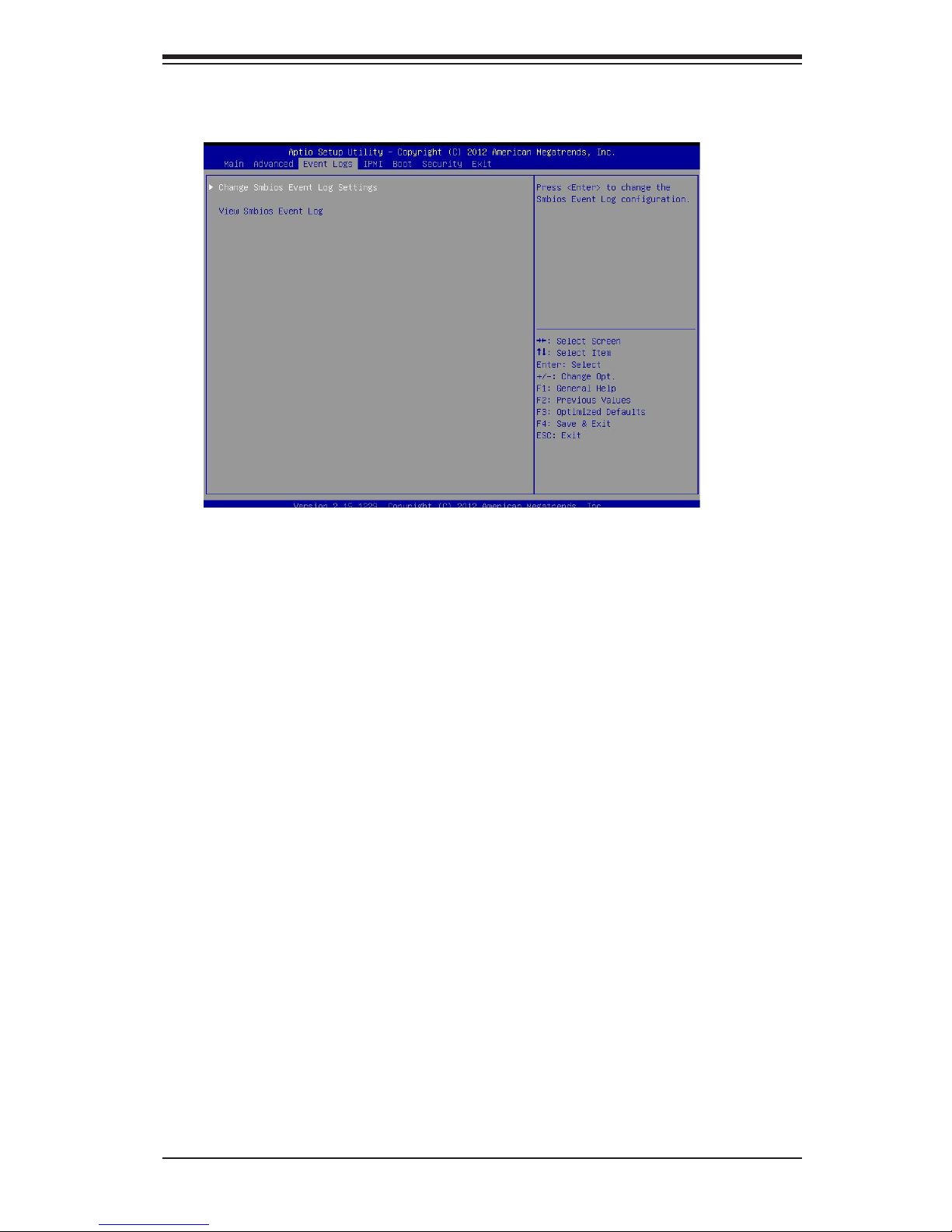
Chapter 4: AMI BIOS
4-17
Change Smbios Event Log Settings
The following options are available:
Smbios Event Log
Change this item to enable or disable all features of the Smbios Event Logging
during boot. The options are Enabled and Disabled.
Erase Event Log
This option erases all logged events. The options are No, Yes, Next reset and
Yes, Every reset.
When Log is Full
This option automatically clears the Event Log memory of all messages when
it is full. The options are Do Nothing and Erase Immediately.
MECI
The Multiple Event Count Increment (MECI) counter counts the number of occur-
rences a duplicate event must happen before the MECI counter is incremented.
This is a numeric value.
4-4 Event Logs
Page 64
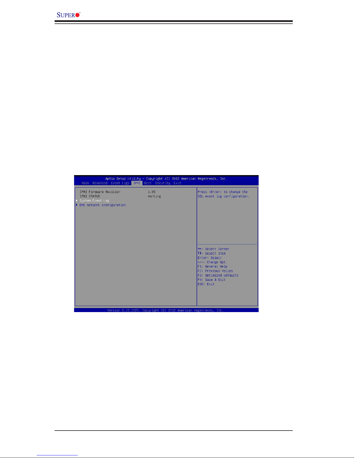
4-18
X9SCE-F User’s Manual
System Event Log
This feature is used to change the System Event Log (SEL) conguration.
SEL Components - Change this item to enable or disable all features of System
Event Logging. The options are Enabled and Disabled. When Enabled, the
following can be congured:
Erase SEL - This option erases all logged SEL events. The options are No,
Yes, On Next reset and Yes, On Every reset.
METW
The Multiple Event Time Window (METW) denes number of minutes must pass
between duplicate log events before MECI is incremented. This is in minutes,
from 0 to 99.
View Smbios Event Log
Displays the Smbios Event Log stored in memory.
4-5 IPMIConguration
Intelligent Platform Management Interface (IPMI) is a set of common interfaces that
IT administrators can use to monitor system health and to manage the system as a
whole. For more information on the IPMI specications, please visit Intel's website
at www.intel.com.
Page 65

Chapter 4: AMI BIOS
4-19
When SEL Full
This option automatically clears the System Event Log memory of all messages
when it is full. The options are Do Nothing and Erase Immediately.
BMCNetworkConguration
Set this feature to congure the IPMI LAN adapter with a network address.
UpdateIPMILANConguration
Select Yes to update the IPMI LAN conguration. The options are Yes and No.
CongurationAddressSource
This feature selects whether the IP address, Subnet Mask and Gateway Address
are automatically assigned by the network's DHCP server (Dynamic Host and Con-
guration Protocol) "Dynamic" or manually entered by the user "Static". If Static is
selected, the IP Address, Subnet Mask and Gateway Address must be manually
entered below. The options are Static, Dynamic and Do Nothing. The following
items are displayed when Static is selected:
Current IP Address - Enter the IP address for this machine. This should be in
decimal and in dotted quad form (i.e., 192.168.10.253). The value of each three-
digit number separated by dots should not exceed 255.
Current Subnet Mask - Subnet masks tell the network which subnet this ma-
chine belongs to. The value of each three-digit number separated by dots should
not exceed 255.
Current Station MAC Address - MAC addresses are 6 two-digit hexadecimal
numbers (Base 16, 0 ~ 9, A, B, C, D, E, F) separated by dots (i.e., 00.30.48.
D0.D4.60).
Current Gateway IP Address - Enter the Gateway or Router address this ma-
chine will use (i.e., 192.168.10.1).
Page 66
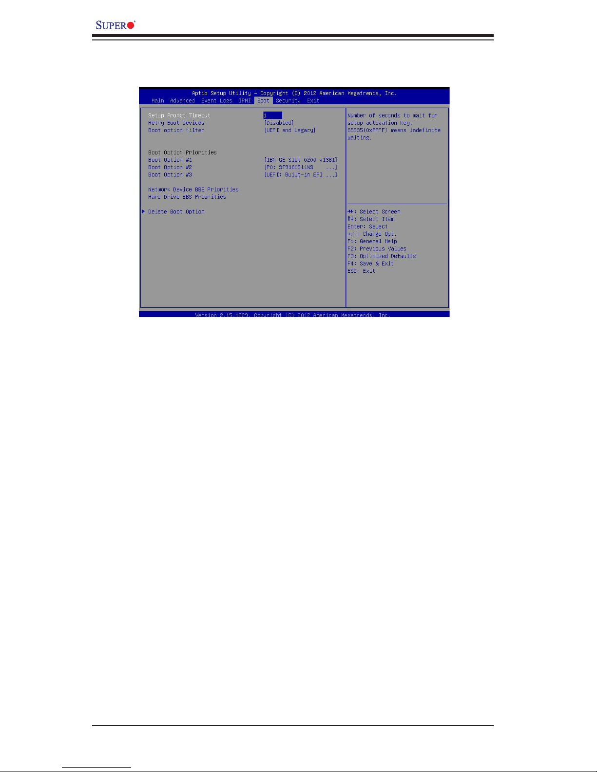
4-20
X9SCE-F User’s Manual
Use this feature to congure Boot Settings:
Setup Prompt Timeout
Number of seconds to wait for setup activation key. Enter 65535 (0xFFFF) to
wait indenitely.
Retry Boot Devices
Select this option to retry booting from the congured boot devices if the systems
fail to boot initially. The options are Disabled and Enabled.
Boot Option Filter
Use this feature to control what devices the system can boot from. The options are
UEFI and Legacy, Legacy Only, and UEFI Only.
Boot Option #1, Boot option #2, Boot Option #3, etc
The settings are Built-in EFI Shell, [any detected boot device] and Disabled.
Network Device BBS Priorities
This feature displays the settings of boot devices detected by the BIOS.
Delete Boot Option
This feature allows the user to delete any previously-dened boot device from the
Boot Options Priority.
4-6 Boot
Page 67
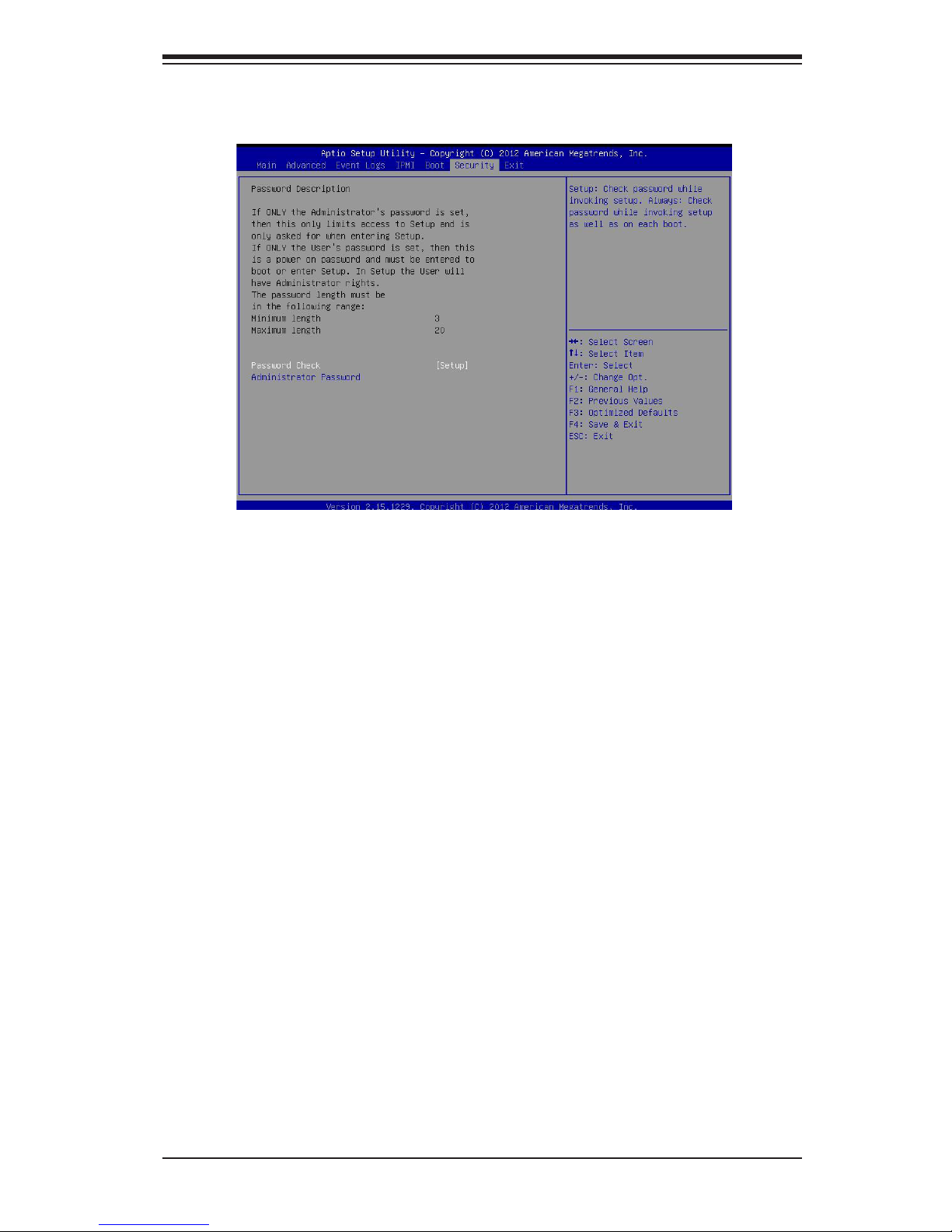
Chapter 4: AMI BIOS
4-21
Password Check
Use this feature to determine when a password entry is required. Select Setup to
require the password only when entering setup. Select Always to require the pass-
word when entering setup and on each boot. The options are Setup and Always.
Administrator Password
Use this feature to set the Administrator Password which is required to enter the
BIOS setup utility. The length of the password should be from 3 characters to 20
characters long.
4-7 Security
Page 68
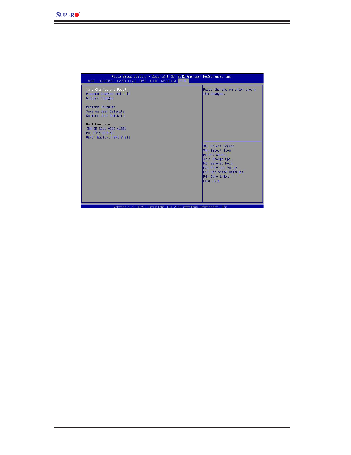
4-22
X9SCE-F User’s Manual
Save Changes and Reset
When you have completed the system conguration changes, select this option
to leave the BIOS Setup Utility and reboot the computer, so that the new system
conguration parameters can take effect. Select Save Changes and Reset from the
Exit menu and press <Enter>.
Discard Changes and Exit
Select this option to quit the BIOS Setup without making any permanent changes
to the system conguration, and reboot the computer. Select Discard Changes and
Exit from the Exit menu and press <Enter>.
Discard Changes
Select this option and press <Enter> to discard all the changes and return to the
AMI BIOS Utility Program.
Restore Defaults
To set this feature, select Restore Defaults from the Exit menu and press <Enter>.
These are factory settings designed for maximum system stability, but not for
maximum performance.
4-8 Exit
Select the Exit tab from the BIOS Setup Utility screen to enter the Exit BIOS Setup
screen.
Page 69

Chapter 4: AMI BIOS
4-23
Save As User Defaults
To set this feature, select Save as User Defaults from the Exit menu and press
<Enter>. This enables the user to save any changes to the BIOS setup for future use
Restore User Defaults
To set this feature, select Restore User Defaults from the Exit menu and press <En-
ter>. Use this feature to retrieve user-dened settings that were saved previously.
Boot Override
This feature allows the user to override the Boot Option Priorities setting in the Boot
menu, and instead immediately boot the system with one of the listed devices. This
is a one-time override.
Page 70

4-24
X9SCE-F User’s Manual
Notes
Page 71
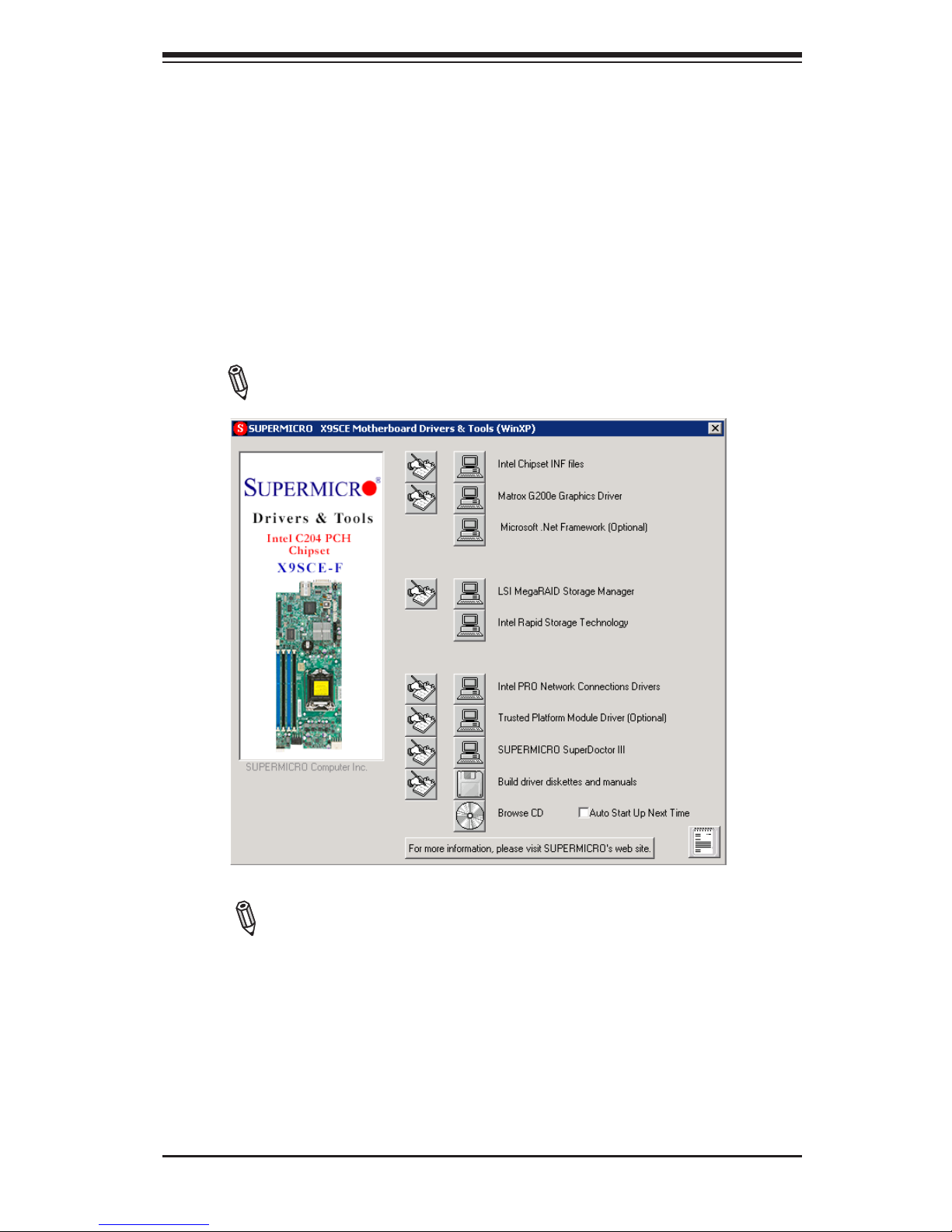
Appendix A: Software Installation Instructions
A-1
Driver/Tool Installation Display Screen
Note 1. Click the icons showing a hand writing on the paper to view the
readme les for each item. Click a computer icon to the right of an item to
install an item (from top to the bottom) one at a time. After installing each
item, you must reboot the system before proceeding with the next item
on the list. The bottom icon with a CD on it allows you to view the entire
contents of the CD.
Note 2. When making a storage driver diskette by booting into a Driver
CD, please set the SATA Conguration to "Compatible Mode" and congure
SATA as IDE in the BIOS Setup. After making the driver diskette, be sure
to change the SATA settings back to your original settings.
Appendix A
Software Installation Instructions
A-1 Installing Software Programs
After you've installed the operating system, a screen as shown below will appear.
You are ready to install software programs and drivers that have not yet been in-
stalled. To install these programs, click the icons to the right of these items.
Note: To install the Windows OS, please refer to the instructions posted
on our Website at http://www.supermicro.com/support/manuals/.
Page 72
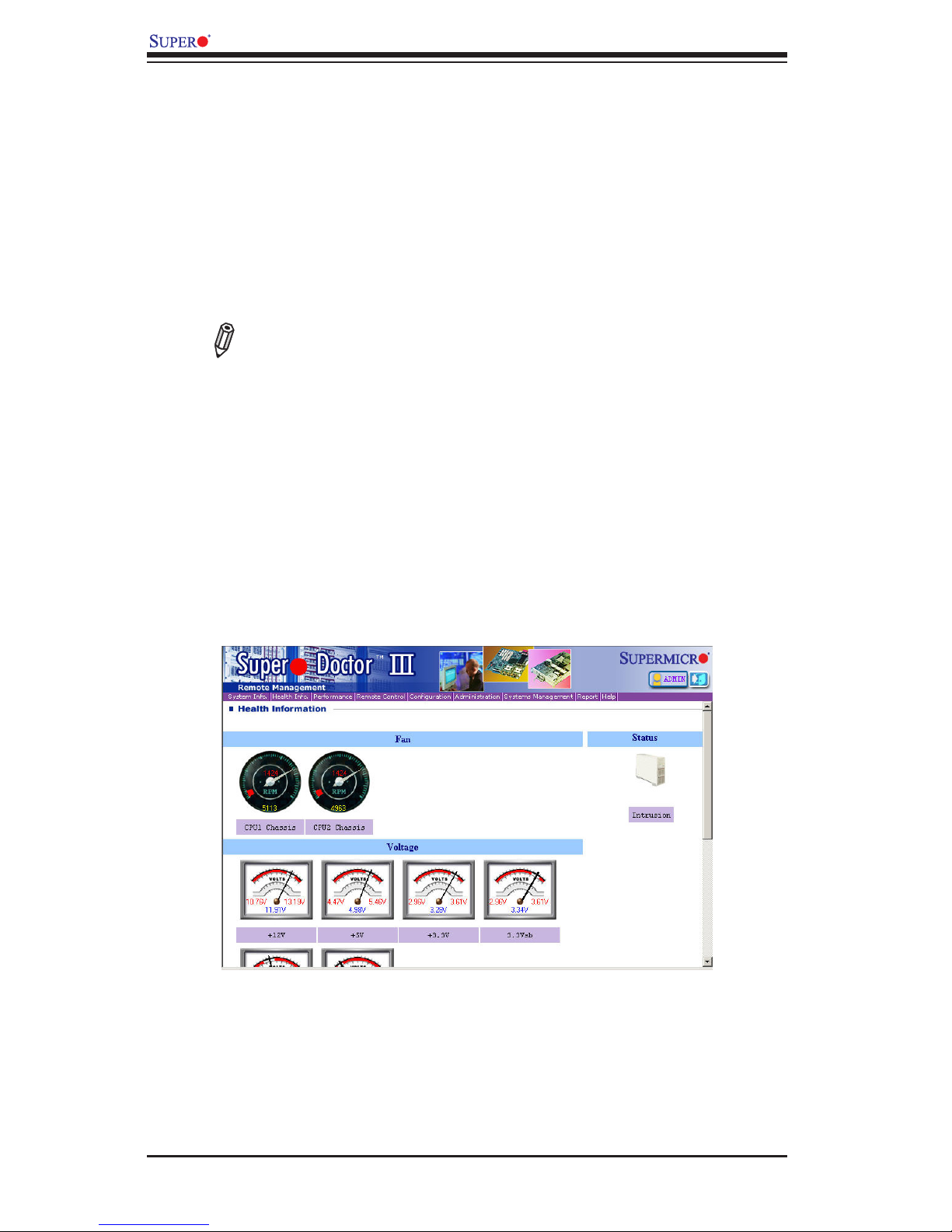
A-2
X9SCE-F Motherboard User’s Manual
SuperDoctor III Interface Display Screen-I (Health Information)
A-2 ConguringSuperDoctorIII
The SuperDoctor III program is a Web-based management tool that supports remote
management capability. It includes Remote and Local Management tools. The local
management is called the SD III Client. The SuperDoctor III program included on the
CDROM that came with your motherboard allows you to monitor the environment
and operations of your system. SuperDoctor III displays crucial system information
such as CPU temperature, system voltages and fan status. See the Figure below
for a display of the SuperDoctor III interface.
Note: 1 The default user name and password are ADMIN.
Note 2: In the Windows OS environment, the SuperDoctor III settings take
precedence over the BIOS settings. When rst installed, SuperDoctor III
adopts the temperature threshold settings previously set in BIOS. Any
subsequent changes to these thresholds must be made within SuperDoc-
tor, since the SD III settings override the BIOS settings. For the Windows
OS to adopt the BIOS temperature threshold settings, please change the
SDIII settings to be the same as those set in BIOS.
Page 73
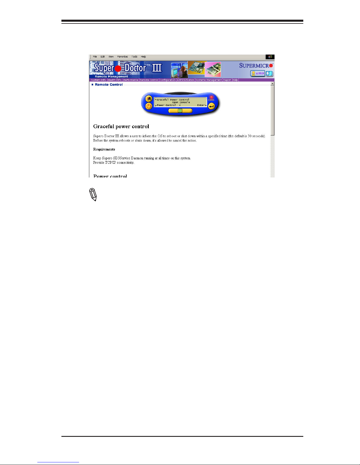
Appendix A: Software Installation Instructions
A-3
SuperDoctor III Interface Display Screen-II (Remote Control)
Note: The SD III utility and user guide can be downloaded from our
website at: http://www.supermicro.com/products/accessories/software/
SuperDoctorIII.cfm. For Linux, we will still recommend that you use
Supero Doctor II.
Page 74

A-4
X9SCE-F Motherboard User’s Manual
Notes
Page 75

Appendix B: UEFI BIOS Recovery
B-1
Appendix B
UEFI BIOS Recovery Instructions
Warning! Do not upgrade the BIOS unless your system has a BIOS-related issue.
Flashing the wrong BIOS can cause irreparable damage to the system. In no event shall
Supermicro be liable for direct, indirect, special, incidental, or consequential damages
arising from a BIOS update. If you need to update the BIOS, do not shut down or reset
the system while the BIOS is updating to avoid possible boot failure.
B-1 An Overview to the UEFI BIOS
The Unied Extensible Firmware Interface (UEFI) specication provides a software-
based interface between the operating system and the platform rmware in the
pre-boot environment. The UEFI specication supports an architecture-independent
mechanism for add-on card initialization to allow the UEFI OS loader, which is stored
in the add-on card, to boot up the system. UEFI offers a clean, hand-off control to
a computer system at bootup.
B-2 How to Recover the UEFI BIOS Image (-the Main
BIOS Block)
An AMIBIOS ash chip consists of a boot sector block and a main BIOS code block
(a main BIOS image). The boot sector block contains critical BIOS codes, including
memory detection and recovery codes for the user to ash a new BIOS image if the
original BIOS image is corrupted. When the system power is on, the boot sector
codes execute rst. Once it is completed, the main BIOS code will continue with
system initialization and bootup.
Note: Follow the BIOS Recovery instructions below for BIOS recovery
when the main BIOS block crashes. However, when the BIOS Boot sec-
tor crashes, you will need to send the motherboard back to Supermicro
for RMA repair.
B-3 To Recover the Main BIOS Block Using a USBAttached Device
This feature allows the user to recover a BIOS image using a USB-attached device
without additional utilities used. A USB ash device such as a USB Flash Drive, or
a USB CD/DVD ROM/RW device can be used for this purpose. However, a USB
Hard Disk drive cannot be used for BIOS recovery at this time.
Page 76
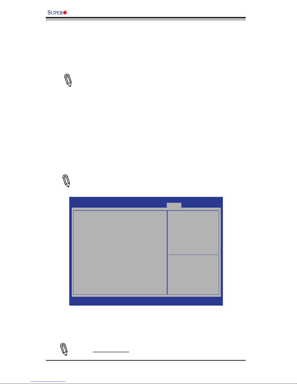
B-2
X9SCE-F User’s Manual
5. When the screen as shown above displays, using the arrow key, select the
item- "Proceed with ash update" and press the <Enter> key. You will see the
progress of BIOS Recovery as shown in the screen below.
Note: Do not interrupt the process of BIOS ashing until it is completed.
To perform UEFI BIOS recovery using a USB-attached device, follow the instruc-
tions below.
1. Using a different machine, copy the "Super.ROM" binary image le into the
disc Root "\" Directory of a USB device or a writeable CD/DVD.
Note: If you cannot locate the "Super.ROM" le in your driver disk, visit
our website at www.supermicro.com to download the BIOS image into a
USB ash device and rename it to "Super ROM" for BIOS recovery use.
2. Insert the USB device that contains the new BIOS image ("Super.Rom") into
your USB drive and power on the system
3. While powering on the system, keep pressing <Ctrl> and <Home> simultane-
ously on your PS2 or USB keyboard until your hear two short beeps. This
may take from a few seconds to one minute.
4. After locating the new BIOS binary image, the system will enter the BIOS
Recovery page as shown below.
Note: At this point, you may decide if you want to start with BIOS Recovery.
If you decide to proceed with BIOS Recovery, follow the procedures below.
Aptio Setup Utility - Copyright (C) 2011 American Megatrends, Inc.
Main Advanced Event Logs IPMI Boot Security Exit
: Select Screen
: Select Item
Enter: Select
+/- : Change Opt.
F1 : General Help
F2 : Previous Values
F3 : Optimized Defaults
F4 : Save & Exit
ESC : Exit
Version 2.12.1211. Copyright (C) 2011 American Megatrends, Inc.
WARNING! BIOS Recovery Mode has been detected
Set this to start ash
update
Recovery
Flash Update Parameters
Reset NVRAM
[Enabled]
Proceed with Flash Update
Page 77
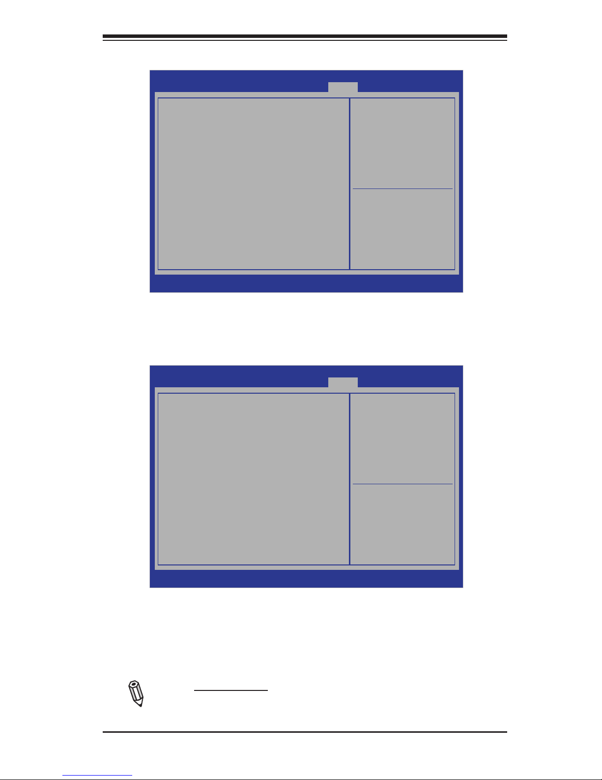
Appendix B: UEFI BIOS Recovery
B-3
6. After the process of BIOS Recovery is complete, press any key to reboot the
system
Aptio Setup Utility - Copyright (C) 2011 American Megatrends, Inc.
: Select Screen
: Select Item
Enter: Select
+/- : Change Opt.
F1 : General Help
F2 : Previous Values
F3 : Optimized Defaults
F4 : Save & Exit
ESC : Exit
Version 2.12.1211. Copyright (C) 2011 American Megatrends, Inc.
WARNING! System rmware is being updated.
Recovery
Keyboard is locked.
DO NOT TURN THE POWER OFF!!!
Once rmware update is completed
press any key to reboot the system
Flash update progress 47%
7. Using a different system, extract the BIOS package into a bootable USB ash
drive.
8. When a DOS prompt appears, type AMI.BAT BIOSname.### at the prompt.
Note: Do not interrupt this process until BIOS ashing is completed.
Aptio Setup Utility - Copyright (C) 2011 American Megatrends, Inc.
: Select Screen
: Select Item
Enter: Select
+/- : Change Opt.
F1 : General Help
F2 : Previous Values
F3 : Optimized Defaults
F4 : Save & Exit
ESC : Exit
Version 2.12.1211. Copyright (C) 2011 American Megatrends, Inc.
WARNING! System rmware is being updated.
Recovery
Keyboard is locked.
DO NOT TURN THE POWER OFF!!!
Once rmware update is completed
press any key to reboot the system
Flash update progress Completed.
Page 78

B-4
X9SCE-F User’s Manual
9. After seeing the message that BIOS update is completed, unplug the AC
power cable to clear CMOS, and then plug in the AC power cable to power
on the system.
10. Press <Del> continuously to enter the BIOS Setup utility.
11. Press <F3> to load default settings.
12. After loading default settings, press <F4> to save the settings and exit the
BIOS Setup utility.
Page 79

Disclaimer
The products sold by Supermicro are not intended for and will not be used in life support systems, medical equipment, nuclear facilities or systems, aircraft, aircraft devices,
aircraft/emergency communication devices or other critical systems whose failure to perform be reasonably expected to result in signicant injury or loss of life or catastrophic
property damage. Accordingly, Supermicro disclaims any and all liability, and should buyer use or sell such products for use in such ultra-hazardous applications, it does so
entirely at its own risk. Furthermore, buyer agrees to fully indemnify, defend and hold Supermicro harmless for and against any and all claims, demands, actions, litigation, and
proceedings of any kind arising out of or related to such ultra-hazardous use or sale.
 Loading...