

Supero X9SCAA, X9SCAA-L User Manual

X9SCAA
X9SCAA-L
USER’S MANUAL
Revision 1.0

Manual Revision 1.0
Release Date: February 13, 2013
Unless you request and receive written permission from Super Micro Computer, Inc., you may not
copy any part of this document. Information in this document is subject to change without notice.
Other products and companies referred to herein are trademarks or registered trademarks of their
respective companies or mark holders.
Copyright © 2012 by Super Micro Computer, Inc. All rights reserved.
Printed in the United States of America
The information in this User’s Manual has been carefully reviewed and is believed to be accurate.
The vendor assumes no responsibility for any inaccuracies that may be contained in this document,
makes no commitment to update or to keep current the information in this manual, or to notify any
person or organization of the updates. Please Note: For the most up-to-date version of this
manual, please see our web site at www.supermicro.com.
Super Micro Computer, Inc. ("Supermicro") reserves the right to make changes to the product
described in this manual at any time and without notice. This product, including software and documentation, is the property of Supermicro and/or its licensors, and is supplied only under a license.
Any use or reproduction of this product is not allowed, except as expressly permitted by the terms
of said license.
IN NO EVENT WILL SUPER MICRO COMPUTER, INC. BE LIABLE FOR DIRECT, INDIRECT,
SPECIAL, INCIDENTAL, SPECULATIVE OR CONSEQUENTIAL DAMAGES ARISING FROM THE
USE OR INABILITY TO USE THIS PRODUCT OR DOCUMENTATION, EVEN IF ADVISED OF
THE POSSIBILITY OF SUCH DAMAGES. IN PARTICULAR, SUPER MICRO COMPUTER, INC.
SHALL NOT HAVE LIABILITY FOR ANY HARDWARE, SOFTWARE, OR DATA STORED OR USED
WITH THE PRODUCT, INCLUDING THE COSTS OF REPAIRING, REPLACING, INTEGRATING,
INSTALLING OR RECOVERING SUCH HARDWARE, SOFTWARE, OR DATA.
Any disputes arising between manufacturer and customer shall be governed by the laws of Santa
Clara County in the State of California, USA. The State of California, County of Santa Clara shall
be the exclusive venue for the resolution of any such disputes. Supermicro's total liability for all
claims will not exceed the price paid for the hardware product.
FCC Statement: This equipment has been tested and found to comply with the limits for a Class B
digital device pursuant to Part 15 of the FCC Rules. These limits are designed to provide reasonable protection against harmful interference in a residential installation. This equipment generates,
uses, and can radiate radio frequency energy and, if not installed and used in accordance with the
manufacturer’s instruction manual, may cause interference with radio communications. However,
there is no guarantee that interference will not occur in a particular installation. If this equipment
does cause harmful interference to radio or television reception, which can be determined by turning the equipment off and on, you are encouraged to try to correct the interference by one or more
of the following measures:
•Reorient or relocate the receiving antenna.
•Increase the separation between the equipment and the receiver.
•Connect the equipment into an outlet on a circuit different from that to which the
receiver is connected.
•Consult the dealer or an experienced radio/television technician for help.
California Best Management Practices Regulations for Perchlorate Materials: This Perchlorate warning applies only to products containing CR (Manganese Dioxide) Lithium coin cells. “Perchlorate
Material-special handling may apply. See www.dtsc.ca.gov/hazardouswaste/perchlorate”.
WARNING: Handling of lead solder materials used in this product may expose you to lead, a chemical known to the State of
California to cause birth defects and other reproductive harm.

iii
Preface
About This Manual
This manual is written for system integrators, PC technicians and
knowledgeable PC users. It provides information for the installation and use of
the X9SCAA motherboard product series. This product is intended to be
professionally installed and serviced by a technician.
About This Motherboard
The X9SCAA motherboard series is a value-driven product aimed at users who
demand a reduced-cost, low-power motherboard for control board, network appli-
ance, thin client and many embedded applications.
The X9SCAA motherboard series comes with the Intel® ATOM N2800 CPU installed
and other features such as two SODIMM support, USB 2.0, VGA, and an on-board
LVDS. A VESA DisplayPort, HDMI port, an LVDS header, USB 3.0 and a Mini-PCIe
slot with mSATA are also supported on the X9SCAA. This enables the X9SCAA
motherboardseriestodeliveracost-effective,energyefcient,HDandrichmedia
solution in a mini-ITX form-factor.
Manual Organization
Chapter 1describesthefeatures,specicationsandperformanceofthemainboard
and provides detailed information about the chipset.
Chapter 2 provides hardware installation instructions. Read this chapter when in-
stalling the processor, memory modules and other hardware components into the
system. If you encounter any problems, see Chapter 3, which describes trouble-
shooting procedures for video, memory and system setup stored in the CMOS.
Chapter 4 includes an introduction to the BIOS and provides detailed information
on running the CMOS Setup utility.
Appendix A provides BIOS Error Beep Codes.
Appendix B lists Driver Installation Instructions.
Appendix C provides the UEFI BIOS Recovery Instructions.
Preface

iv
X9SCAA Motherboard Series User’s Manual
Conventions Used in the Manual:
Special attention should be given to the following symbols for proper installation and
to prevent damage done to the components or injury to yourself:
Danger/Caution: Instructions to be strictly followed to prevent catastrophic
system failure or to avoid bodily injury
Warning: Critical information to prevent damage to the components or
data loss.
Important: Important information given to ensure proper system installa-
tion or to relay safety precautions.
Note: Additional Information given to differentiate various models or pro-
vides information for correct system setup.

v
Contacting Supermicro
1-4 Contacting Supermicro
Headquarters
Address: Super Micro Computer, Inc.
980 Rock Ave.
San Jose, CA 95131 U.S.A.
Tel: +1 (408) 503-8000
Fax: +1 (408) 503-8008
Email: marketing@supermicro.com (General Information)
support@supermicro.com (Technical Support)
Web Site: www.supermicro.com
Europe
Address: Super Micro Computer B.V.
Het Sterrenbeeld 28, 5215 ML
's-Hertogenbosch, The Netherlands
Tel: +31 (0) 73-6400390
Fax: +31 (0) 73-6416525
Email: sales@supermicro.nl (General Information)
support@supermicro.nl (Technical Support)
rma@supermicro.nl (Customer Support)
Asia-Pacic
Address: Super Micro Computer, Inc.
4F, No. 232-1, Liancheng Rd
Chung-Ho Dist., New Taipei City 235
Taiwan
Tel: +886-(2) 8226-3990
Fax: +886-(2) 8226-3991
Web Site: www.supermicro.com.tw
Technical Support:
Email: support@supermicro.com.tw
Tel: +886-(2)-8226-3990
vi
X9SCAA Motherboard Series User’s Manual
Table of Contents
Preface
About This Manual ........................................................................................................ iii
About This Motherboard ................................................................................................ iii
Manual Organization .....................................................................................................iii
Conventions Used in the Manual: .................................................................................iv
1-4 Contacting Supermicro ........................................................................................v
Chapter 1
Introduction
1-1 Overview ......................................................................................................... 1-1
Checklist .......................................................................................................... 1-1
X9SCAA Image ........................................................................... 1-2
X9SCAA-L Image ........................................................................ 1-3
X9SCAA Layout ..............................................................................................1-4
X9SCAA-L Layout ........................................................................................... 1-5
X9SCAA / X9SCAA-L Quick Reference .......................................................... 1-6
Jumper Descriptions ....................................................................................... 1-6
Ports, Connectors, LED Indicators.................................................................. 1-7
Motherboard Features ..................................................................................... 1-8
X9SCAA Motherboard Series Block Diagram ............................................... 1-10
1-2 Chipset Overview ..........................................................................................1-11
1-3 PowerCongurationSettings........................................................................ 1-12
Slow Blinking LED for Suspend-State Indicator ........................................... 1-12
BIOS Support for USB Keyboard.................................................................. 1-12
Main Switch Override Mechanism ................................................................ 1-12
1-4 Power Supply ................................................................................................ 1-12
1-5 Super I/O ....................................................................................................... 1-13
Chapter 2
Installation
2-1 Static-Sensitive Devices .................................................................................. 2-1
Precautions ..................................................................................................... 2-1
Unpacking ....................................................................................................... 2-1
Tools Needed .................................................................................................. 2-2
Location of Mounting Holes ............................................................................ 2-2
2-2 Motherboard Installation .................................................................................. 2-2
Installation Instructions .................................................................................... 2-3

vii
Table of Contents
2-3 System Memory .............................................................................................. 2-4
How to Install SODIMMs ................................................................................. 2-4
Memory Support .............................................................................................. 2-4
The SODIMM Socket ...................................................................................... 2-5
2-4 Connectors and I/O Ports ............................................................................... 2-6
Back Panel Connectors and I/O Ports ............................................................ 2-6
Universal Serial Bus (USB 0~7)) ............................................................... 2-7
Serial Ports (COM1~4) ............................................................................... 2-8
VGA Connector (VGA) ............................................................................... 2-9
LAN Ports (LAN1/LAN2) ............................................................................ 2-9
VESA® DisplayPort™ (DisplayPort) ........................................................ 2-10
HDMI Port (HDMI) .................................................................................... 2-10
Front Control Panel ........................................................................................2-11
JF1 Header Pins .......................................................................................2-11
FrontControlPanelPinDenitions............................................................... 2-12
Power LED .............................................................................................. 2-12
HDD LED .................................................................................................. 2-12
NIC1/NIC2 LED Indicators ....................................................................... 2-12
Overheat (OH)/Fan Fail LED.................................................................... 2-13
Reset Button ........................................................................................... 2-13
Power Button ........................................................................................... 2-13
2-5 Connecting Cables ........................................................................................ 2-14
Power Connectors (JPW1) ...................................................................... 2-14
12V DC only 4-pin Power Connector (JPW2) .......................................... 2-14
Fan Headers ............................................................................................. 2-15
Front Panel Audio Header ........................................................................ 2-15
S/PDIF IN, S/PDIF OUT ........................................................................... 2-16
SATA DOM Power .................................................................................... 2-17
Overheat/Fan Fail LED (JOH1) ................................................................ 2-17
Mini PCI-E Slot (Mini PCIE) ..................................................................... 2-18
Power LED/Speaker ................................................................................. 2-19
Internal Speaker/Buzzer ........................................................................... 2-19
TPM Header ............................................................................................. 2-20
LVDS header ........................................................................................... 2-21
2-6 Jumper Settings ............................................................................................ 2-22
Explanation of Jumpers ............................................................................ 2-22
CMOS Clear ............................................................................................. 2-23
USB Wake-Up .......................................................................................... 2-24
Onboard Audio Enable ............................................................................. 2-25

viii
X9SCAA Motherboard Series User’s Manual
LVDS Voltage Select ................................................................................ 2-25
2-7 Onboard Indicators ........................................................................................ 2-26
LAN Port LEDs ......................................................................................... 2-26
Onboard Power LED ................................................................................ 2-27
Suspend LED ........................................................................................... 2-27
2-8 Serial ATA and HDD Connections ................................................................. 2-28
SATA Connections (SATA0, SATA1) ........................................................ 2-28
Chapter 3
Troubleshooting
3-1 Troubleshooting Procedures ........................................................................... 3-1
Before Power On ............................................................................................ 3-1
No Power ........................................................................................................ 3-1
No Video ......................................................................................................... 3-1
Memory Errors ............................................................................................... 3-2
IfYouLosetheSystem’sSetupConguration ............................................... 3-2
3-2 Technical Support Procedures ........................................................................ 3-2
3-3 Frequently Asked Questions ........................................................................... 3-3
3-4 Returning Merchandise for Service................................................................. 3-5
Chapter 4
BIOS
4-1 Introduction ...................................................................................................... 4-1
Starting BIOS Setup Utility .............................................................................. 4-1
HowToChangetheCongurationData ......................................................... 4-1
How to Start the Setup Utility ......................................................................... 4-2
4-2 Main Setup ...................................................................................................... 4-2
System Overview: The following BIOS information will be displayed: ....... 4-3
System Time/System Date ........................................................................ 4-3
Supermicro X9SCAA/-L .............................................................................. 4-3
Processor ................................................................................................... 4-3
System Memory ......................................................................................... 4-3
4-3 AdvancedSetupCongurations...................................................................... 4-4
BOOT Feature .............................................................................................. 4-4
Quiet Boot .................................................................................................. 4-4
AddOn ROM Display Mode ........................................................................ 4-4
Bootup Num-Lock ....................................................................................... 4-4
Wait For 'F1' If Error ................................................................................... 4-4
Interrupt 19 Capture ................................................................................... 4-5

ix
Table of Contents
Re-try Boot ................................................................................................. 4-5
Watch Dog Function ................................................................................... 4-5
Power Button Function ............................................................................... 4-5
Restore on AC Power Loss ........................................................................ 4-5
Processor and Clock Options....................................................................... 4-6
Clock Spread Spectrum ............................................................................. 4-6
Hyper-Threading ......................................................................................... 4-6
Execute-Disable Bit .................................................................................... 4-6
Limit CPUID Maximum ............................................................................... 4-6
Enhanced C State ...................................................................................... 4-7
CPU Hard C4E ........................................................................................... 4-7
C4 Exit Timing ............................................................................................ 4-7
C-State POPDOWN ................................................................................... 4-7
C-State POPUP .......................................................................................... 4-7
IDE/SATAConguration ............................................................................... 4-7
SATA Controllers ........................................................................................ 4-7
SATA Mode Selection ................................................................................. 4-7
IDE Mode ................................................................................................... 4-7
AHCI Mode ................................................................................................. 4-7
Port 0, Port 1 Speed Limit ......................................................................... 4-7
SATA Port 0, SATA Port 1 .......................................................................... 4-8
SATA Port 0, SATA Port 1 Hot Plug ........................................................... 4-8
PCIe/PCI/PnPConguration ....................................................................... 4-8
Other PCI device ROM priority .................................................................. 4-8
PCI Latency Timer ...................................................................................... 4-8
VGA Palette Snoop .................................................................................... 4-8
SLOT1 PCI 33Mhz OPROM ...................................................................... 4-8
Onboard LAN Option ROM Select ............................................................. 4-8
Load Onboard LAN 1 Option ROM, Load Onboard LAN 2 Option ROM .. 4-8
RemoteAccessConguration ...................................................................... 4-9
Serial Port for Out-of-Band Management/Windows Emergency Management
Services (EMS) ........................................................................................ 4-10
Console Redirection (for EMS) ................................................................ 4-10
SuperIOConguration ..............................................................................4-11
Serial Port 1 ..............................................................................................4-11
Serial Port 1 Settings ...............................................................................4-11
Serial Port 2 ............................................................................................. 4-12
Serial Port 2 Settings .............................................................................. 4-12

x
X9SCAA Motherboard Series User’s Manual
Serial Port 3 ............................................................................................. 4-12
Serial Port 3 Settings .............................................................................. 4-12
Serial Port 3 Mode ................................................................................... 4-13
Serial Port 4 ............................................................................................. 4-13
Serial Port 4 Settings .............................................................................. 4-13
HardwareHealthConguration .................................................................. 4-14
Fan Speed Control Mode ......................................................................... 4-14
CPU Temperature, Peripheral Temperature ............................................. 4-14
Fan1 Speed .............................................................................................. 4-14
ACPI Settings ............................................................................................. 4-14
Network Stack ............................................................................................ 4-15
iSCSIConguration ................................................................................... 4-15
Intel® 82574L Gigabit Network Connection ................................................ 4-16
Blink LEDs ............................................................................................... 4-16
PORT CONFIGURATION INFORMATION ............................................... 4-16
4-4 Boot ............................................................................................................... 4 -17
Setup Prompt Timeout ............................................................................. 4-17
Boot Options Priorities ............................................................................. 4-17
Boot Option #1, Boot option #2, Boot Option #3, etc .............................. 4-17
Hard Disk Drives, Network Devices ......................................................... 4-17
Delete Boot Option ................................................................................ 4-17
4-5 Security Settings ........................................................................................... 4-18
Administrator Password .......................................................................... 4-18
User Password: ........................................................................................ 4-18
4-6 Save & Exit ................................................................................................... 4-19
Discard Changes and Exit ...................................................................... 4-19
Save Changes and Reset ........................................................................ 4-19
Save Changes .......................................................................................... 4-19
Discard Changes ...................................................................................... 4-19
Restore Optimized Defaults ..................................................................... 4-20
Save As User Defaults ............................................................................. 4-20
Restore User Defaults .............................................................................. 4-20
Boot Override ........................................................................................... 4-20

xi
Appendix A
POST Error Beep Codes
Recoverable POST Error Beep Codes ......................................................................A-1
Appendix B
Software Installation Instructions
B-1 Installing Software Programs ..........................................................................B-1
B-2 ConguringSuperDoctorIII ............................................................................B-2
Table of Contents

xii
X9SCAA Motherboard Series User’s Manual
Notes

Chapter 1: Introduction
1-1
Chapter 1
Introduction
1-1 Overview
Checklist
Congratulations on purchasing your computer motherboard from an acknowledged
leader in the industry. Supermicro boards are designed with the utmost attention to
detail and to provide you with the highest standards in quality and performance.
Please check that the following items have all been included with your motherboard.
If anything listed here is damaged or missing, contact your retailer.
All the following items are included in the retail box only.
•One (1) Supermicro Mainboard
•Two (2) SATA cables
•One (1) I/O shield
•One (1) Quick Reference Guide
Note: For your system to work properly, please follow the links below to
download all necessary drivers/utilities and the user's manual for your
motherboard.
•SMCI product manuals: http://www.supermicro.com/support/manuals/
•Product Drivers and utilities: ftp://ftp.supermicro.com/
Warning: For safety considerations, please refer to the complete list of
safety warnings posted on the Supermicro website at http://www.supermi-
cro.com/about/policies/safety_information.cfm.
If you have any questions, please contact our support team at support@supermicro.
com.
1-2
X9SCAA Motherboard Series User's Manual
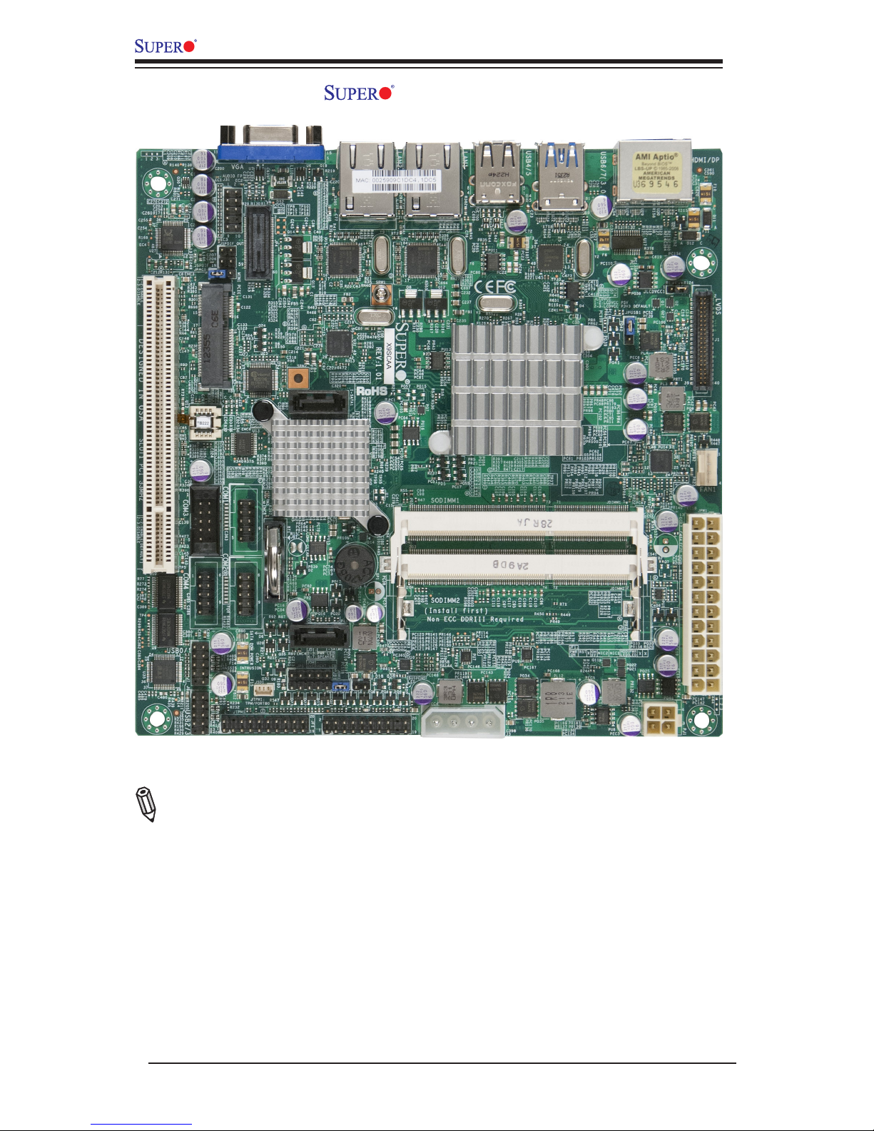
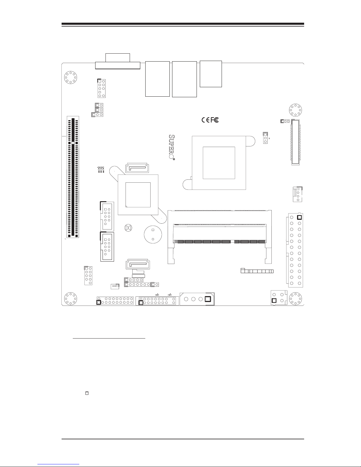
X9SCAA Image
Note: All graphics and images shown in this manual were based upon the latest
PCB Revision available at the time of publishing of the manual. The motherboard
you've received may or may not look exactly the same as the image shown in
this manual.
Chapter 1: Introduction
1-3
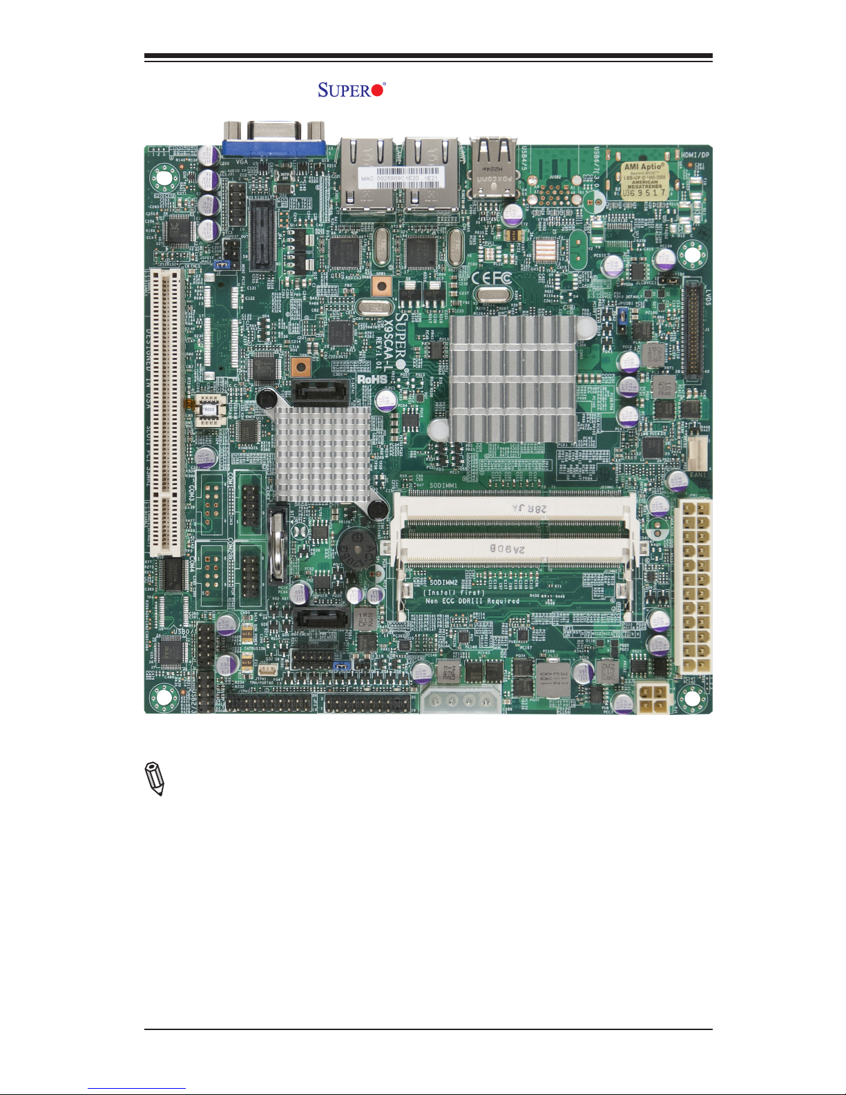
X9SCAA-L Image
Note: All graphics and images shown in this manual were based upon the latest
PCB Revision available at the time of publishing of the manual. The motherboard
you've received may or may not look exactly the same as the image shown in
this manual.
1-4
X9SCAA Motherboard Series User's Manual
1
J1
14
PJ1
1
3
4
JF1
1
2
19
20
JTPM12
19
20
1
JOH1
1
JSPDIF_IN
1
JSPDIF_OUT
JPUSB1
1
JPAC1
1
3
JLCDVCC1
1
JD1
1
JVGA1
11
5
15
6
FAN1
1
4
I-SATA1
I-SATA0
1
2
J2
10
2
7
J7
2
10
J8
7
1
6
9
COM3
COM2COM1
9
1
5
COM4
U10
+
SP1
+
1
JSD1
JBT1
74 72
JDIMM1
2
74
73
71
72
JDIMM2
1
2
A
LED4
C
A
LED3
C
A
LED2
C
CA CA
PRT1
+
U14
DESIGNED IN USA
JPW1
1
(Install rst)
X
Non ECC DDRIII Required
SLOT1 PCI 33MHZ
SATA DOM POWER
JOH1:
OVERHEAT LED
4-7:SPEAKER
1-3:PWR LED
JD1:
LED
SUSPEND
MINI PCIE
LVDS
2-3:LCDVCC P3V3 DEFAULT
1-2:LCDVCC P5V
JLCDVCC
TPM/PORT80
CHASSIS INTRUSION
JL1
JTPM1:
AUDIO FP
USB0/1
USB2/3
1-2:ENABLE
2-3:DISABLE
VGA
JPAC1:ONBOARD AUDIO
LAN2
SODIMM2
SODIMM1
LAN1
USB4/5
PWR
ON
JF1:
RSTOH
FF
X
CPU
USB6/7(3.0)
NIC2 NIC1
HDD
LED
PWR
LED
X
HDMI/DP
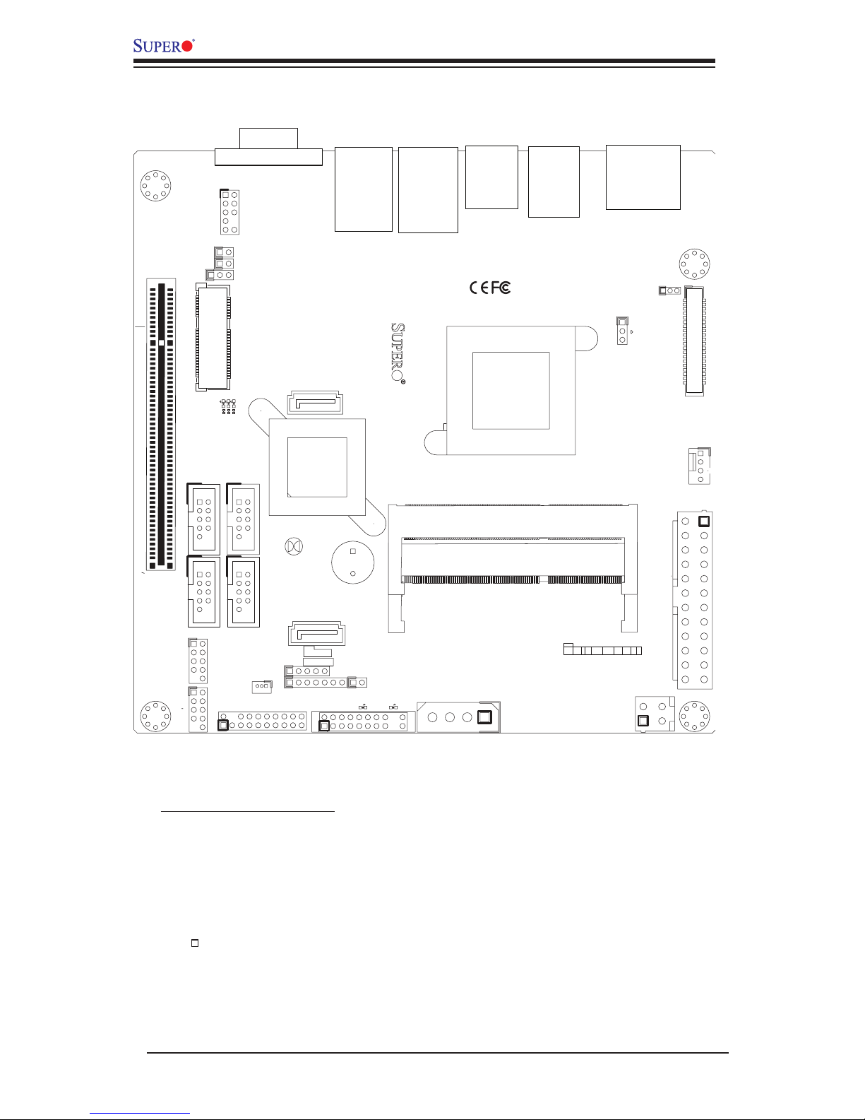
X9SCAA Layout
Important Notes to the User
•Jumpers not indicated are for testing only.
•See Chapter 2 for detailed information on jumpers, I/O ports and JF1 front
panel connections.
•" " indicates the location of "Pin 1".
Chapter 1: Introduction
1-5
1
J1
14
PJ1
1
3
4
JF1
1
2
19
20
JTPM12
19
20
1
JOH1
1
JSPDIF_IN
1
JSPDIF_OUT
JPUSB1
1
JPAC1
1
JLCDVCC1
1
JD1
1
JVGA1
11
5
15
6
FAN1
1
4
I-SATA1
I-SATA0
10
2
7
J7
COM2COM1
9
1
5
U10
+
SP1
+
1
JSD1
JBT1
74 72
JDIMM1
2
74
73
71
72
JDIMM2
1
2
A
LED4
C
A
LED3
C
A
LED2
C
CA CA
PRT1
DESIGNED IN USA
JPW1
1
(Install rst)
X
Non ECC DDRIII Required
SLOT1 PCI 33MHZ
SATA DOM POWER
JOH1:
OVERHEAT LED
4-7:SPEAKER
1-3:PWR LED
JD1:
LED
SUSPEND
MINI PCIE
LVDS
2-3:LCDVCC P3V3 DEFAULT
1-2:LCDVCC P5V
JLCDVCC
TPM/PORT80
CHASSIS INTRUSION
JL1
JTPM1:
AUDIO FP
USB0/1
1-2:ENABLE
2-3:DISABLE
VGA
JPAC1:ONBOARD AUDIO
LAN2
SODIMM2
SODIMM1
LAN1
USB4/5
PWR
ON
JF1:
RSTOH
FF
X
CPU
NIC2 NIC1
HDD
LED
PWR
LED
X
X9SCAA-L Layout
Important Notes to the User
•Jumpers not indicated are for testing only.
•See Chapter 2 for detailed information on jumpers, I/O ports and JF1 front
panel connections.
•" " indicates the location of "Pin 1".
1-6
X9SCAA Motherboard Series User's Manual
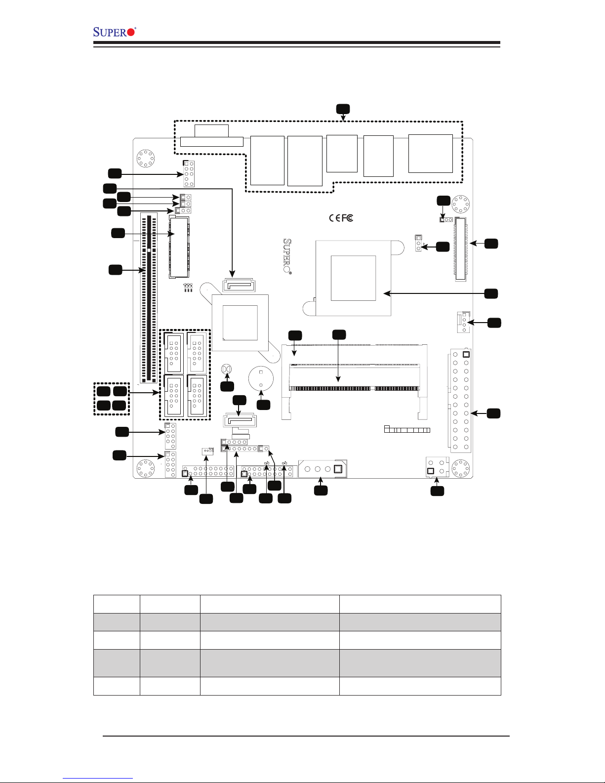
X9SCAA / X9SCAA-L Quick Reference
(not drawn to scale)
Jumper Descriptions
1
J1
14
PJ1
1
3
4
JF1
1
2
19
20
JTPM12
19
20
1
JOH1
1
JSPDIF_IN
1
JSPDIF_OUT
JPUSB1
1
JPAC1
1
3
JLCDVCC1
1
JD1
1
JVGA1
11
5
15
6
FAN1
1
4
I-SATA1
I-SATA0
1
2
J2
10
2
7
J7
2
10
J8
7
1
6
9
COM3
COM2COM1
9
1
5
COM4
U10
+
SP1
+
1
JSD1
JBT1
74 72
JDIMM1
2
74
73
71
72
JDIMM2
1
2
A
LED4
C
A
LED3
C
A
LED2
C
CA CA
PRT1
+
U14
DESIGNED IN USA
JPW1
1
(Install rst)
X
Non ECC DDRIII Required
SLOT1 PCI 33MHZ
SATA DOM POWER
JOH1:
OVERHEAT LED
4-7:SPEAKER
1-3:PWR LED
JD1:
LED
SUSPEND
MINI PCIE
LVDS
2-3:LCDVCC P3V3 DEFAULT
1-2:LCDVCC P5V
JLCDVCC
TPM/PORT80
CHASSIS INTRUSION
JL1
JTPM1:
AUDIO FP
USB0/1
USB2/3
1-2:ENABLE
2-3:DISABLE
VGA
JPAC1:ONBOARD AUDIO
LAN2
SODIMM2
SODIMM1
LAN1
USB4/5
PWR
ON
JF1:
RSTOH
FF
X
CPU
USB6/7(3.0)
NIC2 NIC1
HDD
LED
PWR
LED
X
HDMI/DP
19
202122
23
24
25
26
27
28
34
35
3
4
5
6
7
8
9
10
11 12
13
14
15
16
17
18
2
29
32
30
1
33
31
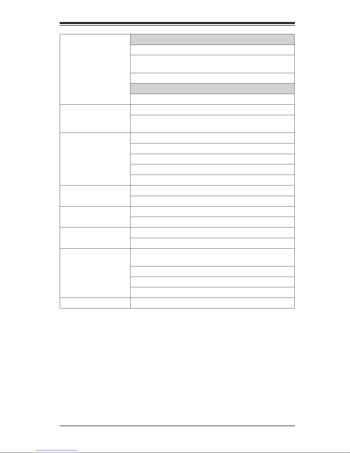
Item # Jumper Description Default
6
JPAC1 Audio Enable/Disable
1-2 (Enabled), 2-3 (Disabled)
29
JLCDVCC1 Voltage Select for LVDS Port
1-2 (5V), 2-3 (3.3V)
30
JPUSB1
USB Wake Up Enable/Disable
on S3/S4/S5.
1-2 (Enabled), 2-3 (Disabled)
31
JBT1 CMOS Reset Short contact pads to reset CMOS
Chapter 1: Introduction
1-7
*X9SCAA Only
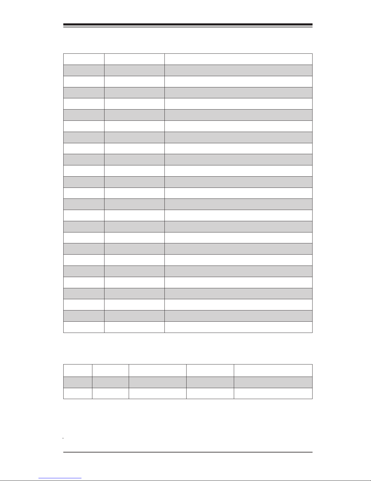
Ports, Connectors, LED Indicators
Item # Connector Description
1
Back Panel I/O
See "Back Panel IO Connectors", page 2-8
2
AUDIO FP Front Panel Audio Header
4
SP/DIF OUT SP/DIF Digital Audio Header (Output)
5
SP/DIF IN SP/DIF Digital Audio Header (Input)
7
Mini PCIE* Mini PCI-E Expansion Slot
8
SLOT1 PCI-33MHz Expansion Slot (5V Key)
9,10,11,12
COM3*,1,4*,2 Internal Headers for COM1~4
13
USB 0/1 Internal Header for USB 0/1
14
USB 2/3* Internal Header for USB 2/3
15
JTPM1 TPM Header
16
JSD1 Disk-On-Module (DOM) Power Header
17
JP5 Reserved for GPIO Programming
18
JD1 External Speaker Header
19
JF1 Front Panel Controls Header
21
JOH1 Overheat Warning LED Header
23
J3 Auxilliary Power Output Header for Internal Devices
24
JPW2 4-Pin 12VDC Only Power Input
25
JPW1 24-Pin ATX Power Input
26
FAN1 CPU Fan Power/Control Header
27
CPU Intel Atom N2800 Series Processor
28
LVDS LVDS Port for VGA (Optional HDMI/Dual Display)
3,32
SATA1,SATA0 Internal SATA Ports
33
SP1 Internal Speaker/Buzzer
34,35 SODIMM1,SODIMM2 SODIMM Memory Slots
Item # LED Description Color/State Status
20
PWR Power LED
Green/Solid Power is On
22
Suspend
Suspend LED
Green/Blinking System in Suspend Mode
1-8
X9SCAA Motherboard Series User's Manual
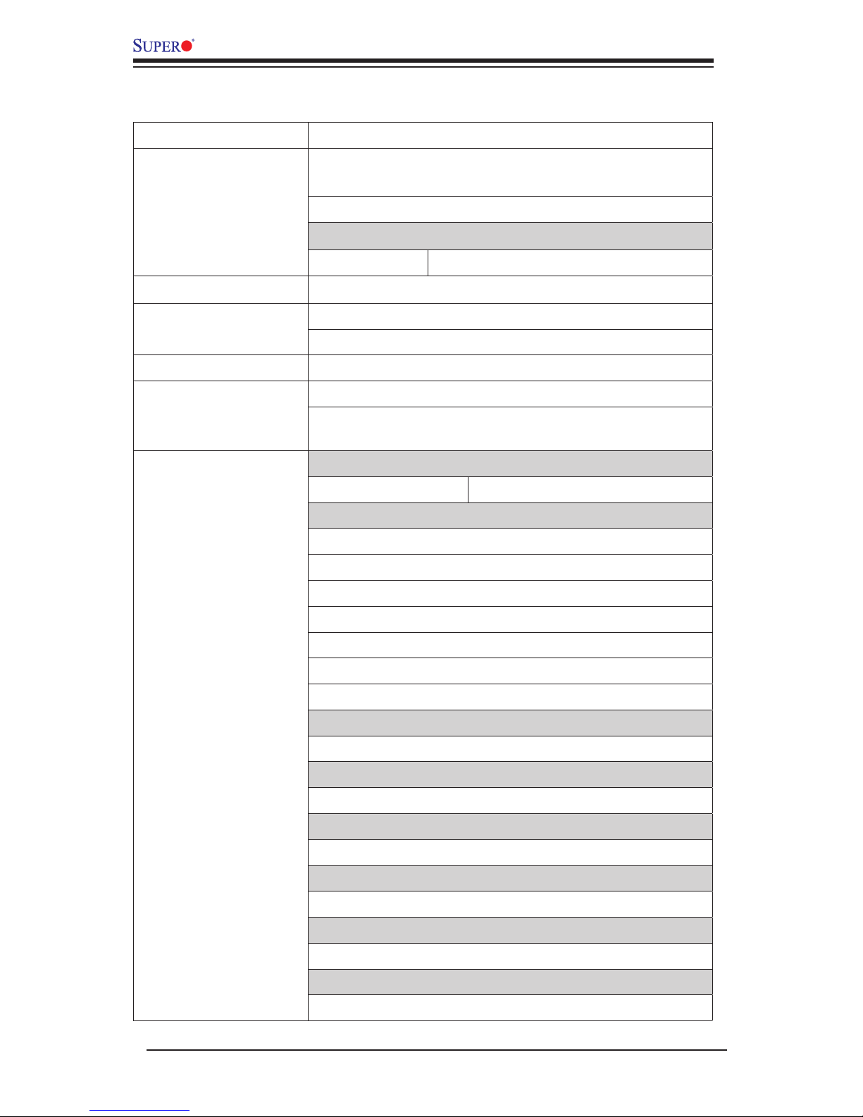
Motherboard Features
CPU Single Intel® ATOM N2800 Series Processor
Memory Two (2) SODIMM slots support up to 4GB of DDR3, unbuf-
fered, 1066 MHz, non-ECC SO-DIMM memory
Supports dual-channel memory bus
DIMM sizes
SODIMM 1GB, 2GB and 4GB
Chipset Intel® NM10 (2.1W)
Expansion Slots One (1) PCI-33MHz Expansion Slot
One Mini PCI-E Slot (full or half card) with mSATA
Graphics Intel GMA 3650
Network Connections Two (2) Intel 82574L
Two (2) RJ-45 Rear IO Panel Connectors with Link and
Activity LEDs
I/O Devices SATA Connections
SATA 2.0 Ports Two (2) (I-SATA0, I-SATA1)
USB Devices
X9SCAA
Two (2) USB 2.0 Ports on the back panel (USB 4/5)
Two (2) USB 3.0 Ports on the back panel (USB 6/7)
Four (4) USB Ports on two headers (USB 0/1, USB 2/3)
X9SCAA-L
Two (2) USB 2.0 Ports on the back panel (USB 4/5)
Four (4) USB Ports on two headers (USB 0/1)
HDMI Port (Back Panel)
X9SCAA only: One (1) HDMI port
VESA DisplayPort (Back Panel)
X9SCAA only: One (1) VESA DisplayPort
LVDS Header
One (1) LVDS Header
VGA Port (Back Panel)
One (1) Back panel VGA port
Audio Devices
One (1) Front Audio Mic/Headphone Header
Keyboard/Mouse
USB Keyboard/Mouse support
Chapter 1: Introduction
1-9
Serial (COM) Ports
Up to four (4) fast UART 16550 connections
X9SCAA: Four (4) COM headers (COM1~4). COM3 with
RS422/RS485.
X9SCAA-L: Two (2) COM headers (COM1, COM2)
Super I/O
ITE IT8760E
BIOS 64 Mb SPI AMI BIOS® SM Flash BIOS
Play and Plug, ACPI 4.0, USB Keyboard and SMBIOS
2.7.1
Power ACPI/ACPM Power Management
Main Switch Override Mechanism
Suspend-To-RAM (STR)
One (1) Disk-On-Module (DOM) Power Connector
Power-on mode for AC power recovery
PC Health Monitoring One (1) 4-pin fan header
Watch Dog
Utilities (Download) BIOS ash upgrade utility
Drivers and software for Intel® NM10 chipset
Other ROHS 6/6 (Full Compliance, Lead Free)
One (1) TPM Header
Operating
Environment Operating Temperature Range: 0°C ~ 60°C (32°F ~ 140°F)
Non-Operating Temperature Range: -20°C ~ 70°C (-4°F ~ 158°F)
Operating Relative Humidity Range: 10% ~ 85% (non-condensing)
Non-Operating Relative Humidity Range:10% ~ 95% (non-condensing)
Dimensions Mini-ITX form factor (6.7" x 6.7"), 8-layers
1-10
X9SCAA Motherboard Series User's Manual
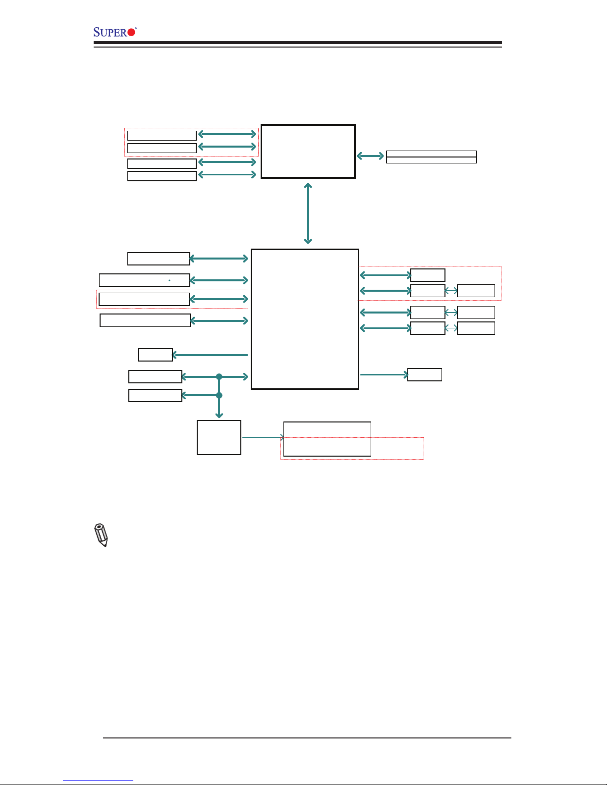
X9SCAA Motherboard Series Block Diagram
Note: This is a general block diagram. Please see the Motherboard Features pages
for details on the features of the motherboard.
LPC
Stacked 2 port rear I/O
COM1 (internal header)
ITE-8760E
GLAN2
82574L
2.5GT/s
Intel ATOM
DDR3 1066 MHz
X9SCAA(-L) BLOCK DIAGRAM
DDI0
HDMI connector
RJ45
RJ45
Non-ECC-SODIMM1
Intel NM10
DMI (X4-Gen1)
2x SATA PORTS
USB2.0
SATA 3Gb/s
PCIe Gen1x1
2.5GT/s
GLAN1
82574L
Debug Header/
USB2.0
4x USB2.0 by Header
SATA[1:0]
USB[3:0]
USB[7:6]
LPC
SPI
TPM HEADER
PCIE[1]
PCIE[2]
PCIE[3]
PCIE[4]
SPI
FLASH
SPI 64Mb
N2800
Non-ECC-SODIMM2 (DEFAULT)
(N2800 only X2)
Single Channel
DDI1
DP connector
LVDS
LVDS connector
VGA
VGA connector
USB2.0
MINI-PCIE
USB[5:4]
COM2 (internal header)
COM3 (internal header)
COM4 (internal header)
PCIe Gen1x1
PCIe Gen1x1 RENESAS
UPD720202
2.5GT/s
PCIe Gen1x1
2.5GT/s
MINI PCIE
SLOT
USB 3.0
Rear I/O
PCI 33
PCI SLOT
PCI
2 Cores/4 Threads
1.86G/ 1M L2 Cache
SIO-W83527HG
(Support RS485/RS422)
MAX. 4G SO-DIMM SUPPORTED
ONLY FOR X9SCAA
ONLY FOR X9SCAA
ONLY FOR X9SCAA
ONLY FOR X9SCAA

Chapter 1: Introduction
1-11
1-2 Chipset Overview
The X9SCAA Motherboard Series supports a single Intel® ATOM N2800 Series
Processor processor. Built upon the functionality and the capability of the Intel
NM10 Express chipset, it enables innovative form factor designs while delivering
mainstream I/O technologies..
The Intel® NM10 Express chipset is part of the mobile series chipset family, with a
single-chip architecture. Among its features are
• 2.1W Power Consumption
• Small form-factor package
• PCI Express 1.0 Interface
• SATA Controller (up to 3Gb/s)
For more information regarding the Intel NM10 Express chipset, please visit Intel's
website at:
http://www.intel.com
or at:
http://www.intel.com/content/www/us/en/chipsets/internet-devices-chipsets/nm10-
chipset.html

1-12
X9SCAA Motherboard Series User's Manual
1-3 PowerCongurationSettings
This section describes features of your motherboard that deal with power and
power settings.
Slow Blinking LED for Suspend-State Indicator
When the CPU goes into a suspend state, the chassis power LED will start blinking
to indicate that the CPU is in suspend mode. When the user presses any key, the
CPU will wake up and the LED will automatically stop blinking and remain on.
BIOS Support for USB Keyboard
If the USB keyboard is the only keyboard in the system, it will function like a normal
keyboard during system boot-up.
Main Switch Override Mechanism
When an ATX power supply is used, the power button can function as a system
suspend button. When the user presses the power button, the system will enter a
Soft Off state. The monitor will be suspended and the hard drive will spin down.
Pressing the power button again will cause the whole system to wake up. During the
SoftOff state, the ATX power supply provides power to keep the required circuitry
in the system "alive." In case the system malfunctions and you want to turn off the
power, just press and hold the power button for 4 seconds. The power will turn off
and no power will be provided to the motherboard.
1-4 Power Supply
As with all computer products, a stable power source is necessary for proper and
reliable operation. It is even more important for processors that have high CPU
clock rates of 1 GHz and faster.
The X9SCAA Motherboard Series accommodates 12V ATX power sup-
plies. Although most power supplies generally meet the specications required by
the CPU, some are inadequate. A 2-Amp of current supply on a 5V Standby rail is
strongly recommended.
Note: The X9SCAA Motherboard Series alternatively supports a 4-pin 12V DC in-
put power supply for embedded applications. However, the motherboard's design
dictates that you only use only one power source for your application.

Chapter 1: Introduction
1-13
1-5 Super I/O
The Super I/O provides two high-speed, 16550 compatible serial communication
ports (UARTs). Each UART includes a 16-byte send/receive FIFO, a programmable
baud rate generator, complete modem control capability and a processor interrupt
system. Both UARTs provide legacy speed with baud rate of up to 115.2 Kbps as
well as an advanced speed with baud rates of 250 K, 500 K, or 1 Mb/s, which sup-
port higher speed modems.
The Super I/O provides functions that comply with ACPI (Advanced Conguration
and Power Interface), which includes support of legacy and ACPI power manage-
ment through a SMI or SCI function pin. It also features auto power management
to reduce power consumption.

1-14
X9SCAA Motherboard Series User's Manual
Notes

Chapter 2: Installation
2-1
Chapter 2
Installation
2-1 Static-Sensitive Devices
Electrostatic-Discharge (ESD) can damage electronic com ponents. To prevent dam-
age to your system board, it is important to handle it very carefully. The following
measures are generally sufcient to protect your equipment from ESD.
Precautions
• Use a grounded wrist strap designed to prevent static discharge.
• Touch a grounded metal object before removing the board from the antistatic
bag.
• Handle the board by its edges only; do not touch its components, peripheral
chips, memory modules or gold contacts.
• When handling chips or modules, avoid touching their pins.
• Put the motherboard and peripherals back into their antistatic bags when not in
use.
• For grounding purposes, make sure your computer chassis provides excellent
conductivity between the power supply, the case, the mounting fasteners and
the motherboard.
• Use only the correct type of onboard CMOS battery. Do not install the onboard
upside down battery to avoid possible explosion.
Unpacking
The motherboard is shipped in antistatic packaging to avoid static damage. When
unpacking the board, make sure the person handling it is static protected.
 Loading...