


X9SBAA
X9SBAA-F
USER’S MANUAL
Revision 1.0a

Manual Revision 1.0a
Release Date: April 15, 2013
Unless you request and receive written permission from Super Micro Computer, Inc., you may not
copy any part of this document. Information in this document is subject to change without notice.
Other products and companies referred to herein are trademarks or registered trademarks of their
respective companies or mark holders.
Copyright © 2013 by Super Micro Computer, Inc. All rights reserved.
Printed in the United States of America
The information in this User’s Manual has been carefully reviewed and is believed to be accurate.
The vendor assumes no responsibility for any inaccuracies that may be contained in this document,
makes no commitment to update or to keep current the information in this manual, or to notify any
person or organization of the updates. Please Note: For the most up-to-date version of this
manual, please see our web site at www.supermicro.com.
Super Micro Computer, Inc. ("Supermicro") reserves the right to make changes to the product
described in this manual at any time and without notice. This product, including software and documentation, is the property of Supermicro and/or its licensors, and is supplied only under a license.
Any use or reproduction of this product is not allowed, except as expressly permitted by the terms
of said license.
IN NO EVENT WILL SUPER MICRO COMPUTER, INC. BE LIABLE FOR DIRECT, INDIRECT,
SPECIAL, INCIDENTAL, SPECULATIVE OR CONSEQUENTIAL DAMAGES ARISING FROM THE
USE OR INABILITY TO USE THIS PRODUCT OR DOCUMENTATION, EVEN IF ADVISED OF
THE POSSIBILITY OF SUCH DAMAGES. IN PARTICULAR, SUPER MICRO COMPUTER, INC.
SHALL NOT HAVE LIABILITY FOR ANY HARDWARE, SOFTWARE, OR DATA STORED OR USED
WITH THE PRODUCT, INCLUDING THE COSTS OF REPAIRING, REPLACING, INTEGRATING,
INSTALLING OR RECOVERING SUCH HARDWARE, SOFTWARE, OR DATA.
Any disputes arising between manufacturer and customer shall be governed by the laws of Santa
Clara County in the State of California, USA. The State of California, County of Santa Clara shall
be the exclusive venue for the resolution of any such disputes. Supermicro's total liability for all
claims will not exceed the price paid for the hardware product.
FCC Statement: This equipment has been tested and found to comply with the limits for a Class B
digital device pursuant to Part 15 of the FCC Rules. These limits are designed to provide reasonable protection against harmful interference in a residential installation. This equipment generates,
uses, and can radiate radio frequency energy and, if not installed and used in accordance with the
manufacturer’s instruction manual, may cause interference with radio communications. However,
there is no guarantee that interference will not occur in a particular installation. If this equipment
does cause harmful interference to radio or television reception, which can be determined by turning the equipment off and on, you are encouraged to try to correct the interference by one or more
of the following measures:
•Reorient or relocate the receiving antenna.
•Increase the separation between the equipment and the receiver.
•Connect the equipment into an outlet on a circuit different from that to which the
receiver is connected.
•Consult the dealer or an experienced radio/television technician for help.
California Best Management Practices Regulations for Perchlorate Materials: This Perchlorate warning applies only to products containing CR (Manganese Dioxide) Lithium coin cells. “Perchlorate
Material-special handling may apply. See www.dtsc.ca.gov/hazardouswaste/perchlorate”.
WARNING: Handling of lead solder materials used in this product may expose you to lead, a chemical known to the State of
California to cause birth defects and other reproductive harm.

iii
Preface
About This Manual
This manual is written for system integrators, PC technicians and
knowledgeable PC users. It provides information for the installation and use of
the X9SBAA motherboard product series. This product is intended to be
professionally installed and serviced by a technician.
About This Motherboard
The X9SBAA motherboard series is a value-driven product aimed at users who
demand a reduced-cost, low-power motherboard for PC, storage, embedded or
micro server platform applications.
The X9SBAA motherboard series comes with the Intel® ATOM SoC S1260
(BGA1283, 8.5W) CPU installed and other features such as ECC-DIMM support,
USB 3.0 ports, SATA 3.0 ports, and on-board VGA and IPMI LAN (X9SBAA-F). This
enables the X9SBAA motherboard series to deliver cost-effective performance in
a small form-factor package.
Manual Organization
Chapter 1describesthefeatures,specicationsandperformanceofthemainboard
and provides detailed information about the chipset.
Chapter 2 provides hardware installation instructions. Read this chapter when in-
stalling the processor, memory modules and other hardware components into the
system. If you encounter any problems, see Chapter 3, which describes trouble-
shooting procedures for video, memory and system setup stored in the CMOS.
Chapter 4 includes an introduction to the BIOS and provides detailed information
on running the CMOS Setup utility.
Appendix A provides BIOS Error Beep Codes.
Appendix B lists Driver Installation Instructions.
Preface

iv
X9SBAA Motherboard Series User’s Manual
Conventions Used in the Manual:
Special attention should be given to the following symbols for proper installation and
to prevent damage done to the components or injury to yourself:
Danger/Caution: Instructions to be strictly followed to prevent catastrophic
system failure or to avoid bodily injury
Warning: Critical information to prevent damage to the components or
data loss.
Important: Important information given to ensure proper system installa-
tion or to relay safety precautions.
Note: Additional Information given to differentiate various models or pro-
vides information for correct system setup.

v
Contacting Supermicro
1-4 Contacting Supermicro
Headquarters
Address: Super Micro Computer, Inc.
980 Rock Ave.
San Jose, CA 95131 U.S.A.
Tel: +1 (408) 503-8000
Fax: +1 (408) 503-8008
Email: marketing@supermicro.com (General Information)
support@supermicro.com (Technical Support)
Web Site: www.supermicro.com
Europe
Address: Super Micro Computer B.V.
Het Sterrenbeeld 28, 5215 ML
's-Hertogenbosch, The Netherlands
Tel: +31 (0) 73-6400390
Fax: +31 (0) 73-6416525
Email: sales@supermicro.nl (General Information)
support@supermicro.nl (Technical Support)
rma@supermicro.nl (Customer Support)
Asia-Pacic
Address: Super Micro Computer, Inc.
4F, No. 232-1, Liancheng Rd
Chung-Ho Dist., New Taipei City 235
Taiwan
Tel: +886-(2) 8226-3990
Fax: +886-(2) 8226-3991
Web Site: www.supermicro.com.tw
Technical Support:
Email: support@supermicro.com.tw
Tel: +886-(2)-8226-3990

vi
X9SBAA Motherboard Series User’s Manual
Table of Contents
Preface
About This Manual ........................................................................................................ iii
About This Motherboard ................................................................................................ iii
Manual Organization .....................................................................................................iii
Conventions Used in the Manual: .................................................................................iv
1-4 Contacting Supermicro ........................................................................................v
Chapter 1
Introduction
1-1 Overview ......................................................................................................... 1-1
Checklist .......................................................................................................... 1-1
X9SBAA Motherboard Series Image ............................................ 1-2
X9SBAA Motherboard Series Layout .............................................................. 1-3
X9SBAA Motherboard Series Quick Reference .............................................. 1-4
Jumper Descriptions ....................................................................................... 1-4
Ports, Connectors, LED Indicators.................................................................. 1-5
Motherboard Features ..................................................................................... 1-6
X9SBAA Motherboard Series Block Diagram ................................................. 1-8
1-2 PowerCongurationSettings.......................................................................... 1-9
Slow Blinking LED for Suspend-State Indicator ............................................. 1-9
BIOS Support for USB Keyboard.................................................................... 1-9
Main Switch Override Mechanism .................................................................. 1-9
1-3 Power Supply .................................................................................................. 1-9
Chapter 2
Installation
2-1 Static-Sensitive Devices .................................................................................. 2-1
Precautions ..................................................................................................... 2-1
Unpacking ....................................................................................................... 2-1
Tools Needed .................................................................................................. 2-2
Location of Mounting Holes ............................................................................ 2-2
2-2 Motherboard Installation .................................................................................. 2-2
Installation Instructions .................................................................................... 2-3
2-3 System Memory .............................................................................................. 2-4
How to Install SO-DIMMs ............................................................................... 2-4
Memory Support .............................................................................................. 2-4
The SO DIMM Socket ..................................................................................... 2-5

vii
Table of Contents
2-4 Connectors and I/O Ports ............................................................................... 2-6
Back Panel Connectors and I/O Ports ............................................................ 2-6
Universal Serial Bus (USB 0/1) .................................................................. 2-7
Serial Port (COM3/COM1) ......................................................................... 2-8
VGA Connector (VGA) ............................................................................... 2-9
LAN Ports (LAN1/LAN2) ............................................................................ 2-9
IPMI LAN (IPMI) ....................................................................................... 2-10
Rear Unit ID Switch (SW1) ...................................................................... 2-10
Front Control Panel ........................................................................................2-11
JF1 Header Pins .......................................................................................2-11
FrontControlPanelPinDenitions............................................................... 2-12
Power LED .............................................................................................. 2-12
HDD LED .................................................................................................. 2-12
NIC1/NIC2 LED Indicators ....................................................................... 2-12
NMI Button .............................................................................................. 2-13
Overheat (OH)/Fan Fail LED.................................................................... 2-13
Reset Button ........................................................................................... 2-13
Power Button ........................................................................................... 2-13
2-5 Connecting Cables ........................................................................................ 2-14
ATX Power Connectors (JPW1) .............................................................. 2-14
Fan Headers (FAN1~3) ............................................................................ 2-15
System Management Bus (JIPMB1) ................................................. 2-15
Chassis Intrusion (JL1) ............................................................................ 2-16
Power Supply I2C (JPI2C1) ...................................................................... 2-16
SATA DOM Power (JSD1) ........................................................................ 2-17
Overheat/Fan Fail LED (JOH1) ................................................................ 2-17
Power LED/Speaker (JD1) ....................................................................... 2-18
Internal Speaker/Buzzer (SP1) ................................................................ 2-18
TPM Header (JTPM1) .............................................................................. 2-19
2-6 Jumper Settings ............................................................................................ 2-20
Explanation of Jumpers ............................................................................ 2-20
BMC Enable/Disable (JPB1) .................................................................... 2-21
VGA Enable (JPG1) ................................................................................. 2-21
CMOS Clear (JBT1) ................................................................................. 2-22
AC On Default (J22) ................................................................................. 2-22
Watch Dog Timer Reset (JWD1) .............................................................. 2-23
LAN Port Enable/Disable (JPL1) .............................................................. 2-23
2-7 Onboard Indicators ........................................................................................ 2-24
LAN Port LEDs ......................................................................................... 2-24

viii
X9SBAA Motherboard Series User’s Manual
IPMI Dedicated LAN Port ......................................................................... 2-24
System Power LED (LE1) ........................................................................ 2-25
IPMI Heartbeat LED (DM1) ...................................................................... 2-25
Rear UID LED (UID) ................................................................................ 2-25
2-8 Serial ATA and HDD Connections ................................................................. 2-26
SATA Connections (SATA0~3) ................................................................. 2-26
Chapter 3
Troubleshooting
3-1 Troubleshooting Procedures ........................................................................... 3-1
Before Power On ............................................................................................ 3-1
No Power ........................................................................................................ 3-1
No Video ......................................................................................................... 3-1
Memory Errors ............................................................................................... 3-2
IfYouLosetheSystem’sSetupConguration ............................................... 3-2
3-2 Technical Support Procedures ........................................................................ 3-2
3-3 Frequently Asked Questions ........................................................................... 3-3
3-4 Returning Merchandise for Service................................................................. 3-5
Chapter 4
BIOS
4-1 Introduction ...................................................................................................... 4-1
Starting BIOS Setup Utility .............................................................................. 4-1
HowToChangetheCongurationData ......................................................... 4-1
How to Start the Setup Utility ......................................................................... 4-2
4-2 Main Setup ...................................................................................................... 4-2
System Overview: The following BIOS information will be displayed: ....... 4-3
System Time/System Date ........................................................................ 4-3
Supermicro X9SBAA .................................................................................. 4-3
Memory Information ................................................................................... 4-3
Platform Information ................................................................................... 4-3
4-3 AdvancedSetupCongurations...................................................................... 4-4
BOOT Feature .............................................................................................. 4-4
Quiet Boot .................................................................................................. 4-4
AddOn ROM Display Mode ........................................................................ 4-4
Bootup Num-Lock ....................................................................................... 4-4
Interrupt 19 Capture ................................................................................... 4-4
Watch Dog Function ................................................................................... 4-5
CPUConguration ....................................................................................... 4-5

ix
Table of Contents
Intel SpeedStep Spectrum ......................................................................... 4-5
Hyper Threading ......................................................................................... 4-5
Execute-Disable Bit (Available when supported by the OS and the CPU) 4-5
Limit CPUID Maximum ............................................................................... 4-5
Intel® Virtualization Technology (Available when supported by the CPU) 4-5
TM Support ................................................................................................. 4-6
C-States ...................................................................................................... 4-6
Enhanced C1 .............................................................................................. 4-6
Enhanced C2 .............................................................................................. 4-6
Enhanced C3 .............................................................................................. 4-6
Enhanced C4 .............................................................................................. 4-6
ChipsetConguration ................................................................................... 4-6
NorthBridgeChipsetConguration ......................................................... 4-6
PMU Clock Gating ...................................................................................... 4-6
PMU Clock Gating ...................................................................................... 4-6
UNIT Clock Gating ..................................................................................... 4-7
Fast Boot .................................................................................................... 4-7
Memory Test ............................................................................................... 4-7
MRC Debug Messages .............................................................................. 4-7
DIMM vref Override .................................................................................... 4-7
MRC Reset Loop ........................................................................................ 4-7
ECC Support .............................................................................................. 4-7
Patrol Scrub Enable ................................................................................... 4-7
Patrol Scrub Period .................................................................................... 4-7
Demand Scrub Enable ............................................................................... 4-8
DDR Low Voltage ....................................................................................... 4-8
Rank Margin Tool ....................................................................................... 4-8
Dynamic Self Refresh ................................................................................ 4-8
Open Page Policy Timer ............................................................................ 4-8
Memory Performance DMap ...................................................................... 4-8
BWFLUSH .................................................................................................. 4-8
Scrambler ................................................................................................... 4-8
Uncore Thermal Throttle ............................................................................ 4-8
Set the following for Default Thermal Enforcement for Thermal Trips ...... 4-9
SchWriteMask,
SchReadMask,
MemoryRankWriteMask,
MemoryRankReadMask ............................................................................. 4-9
Set the following for Lowest Thermal Enforcement Limits......................... 4-9

x
X9SBAA Motherboard Series User’s Manual
SchWriteMask,
SchReadMask,
MemoryRankWriteMask,
MemoryRankReadMask ............................................................................. 4-9
P_RTF_THERM.......................................................................................... 4-9
SouthBridgeChipsetConguration ........................................................ 4-9
PPMCong ............................................................................................. 4-9
C-state POPUP .......................................................................................... 4-9
USBConguration ................................................................................... 4-9
Legacy USB Support .................................................................................. 4-9
USB 3.0 Support ...................................................................................... 4-10
USB Mass Storage Driver Support .......................................................... 4-10
PCIe/PCI/PnPConguration ..................................................................... 4-10
Launch Storage OpROM Policy ............................................................... 4-10
Launch Video OpROM Policy .................................................................. 4-10
PCI Latency Timer .................................................................................... 4-10
PERR# Generation ................................................................................... 4-10
SERR# Generation ................................................................................... 4-10
Maximum Payload .....................................................................................4-11
Maximum Read Request ...........................................................................4-11
ASPM Support ...........................................................................................4-11
Onboard LAN Option ROM Select ............................................................4-11
Load Onboard LAN1 Option ROM / Load Onboard LAN2 Option ROM ..4-11
Network Stack ...........................................................................................4-11
ACPIConguration ......................................................................................4-11
High Precision Timer .................................................................................4-11
Trusted Computing ..................................................................................... 4-12
TPM Support ................................................................................................. 4-12
TPM State ................................................................................................ 4-12
Pending operation .................................................................................... 4-12
Pending operation .................................................................................... 4-12
HardwareHealthConguration .................................................................. 4-12
Fan Speed Control Mode ......................................................................... 4-12
CPU, System, Peripheral Temperature .................................................... 4-12
Fan1 ~ Fan3 Speed ................................................................................. 4-13
+5V, +12V, 5VSB, VDIMM, +1.05V, +3.3V, +3.3VSB, VBAT ................... 4-13
SuperIODeviceConguration ................................................................. 4-13
SerialPort1Conguration/SerialPort2Conguration(SOL) ........... 4-13

xi
Serial Port ................................................................................................. 4-13
Change Settings ....................................................................................... 4-13
Device Mode ............................................................................................ 4-13
ClockGenConguration ............................................................................ 4-14
Clock Spread Spectrum ........................................................................... 4-14
Serial Port Console Redirection ................................................................. 4-14
Intel® I350 Gigabit Network Connection (x2) ............................................. 4-16
Blink LEDs ............................................................................................... 4-16
PORT CONFIGURATION INFORMATION ............................................... 4-16
4-4 Event Logs .................................................................................................... 4-17
Change SmBIOS Event Log Settings ........................................................ 4-17
Smbios Event Log .................................................................................... 4-17
Runtime Error Logging Support ............................................................... 4-17
PCI Error Logging Support ....................................................................... 4-17
Corr Error Threshold ................................................................................ 4-17
Erase Event Log ....................................................................................... 4-17
When Log is Full ...................................................................................... 4-17
Log System Boot Event ........................................................................... 4-18
MECI ......................................................................................................... 4-18
METW ....................................................................................................... 4-18
View SmBIOS Event Log ........................................................................... 4-18
4-5 IPMI .............................................................................................................. 4-19
System Event Log ................................................................................. 4-19
When SEL Full ......................................................................................... 4-19
Log EFI Status Codes .............................................................................. 4-19
BMCNetworkConguration .................................................................. 4-19
UpdateIPMILANConguration ............................................................... 4-20
CongurationSource ................................................................................ 4-20
4-6 Boot Settings ................................................................................................. 4-21
Boot Options Priorities ............................................................................. 4-21
Boot Option #1, Boot option #2, etc......................................................... 4-21
Network Device BBS Priorities, Hard Drive BBS Prioirities ..................... 4-21
Delete Boot Option ................................................................................ 4-21
4-8 Security Settings ........................................................................................... 4-22
Administrator Password .......................................................................... 4-22
User Password: ........................................................................................ 4-22
4-8 Save & Exit ................................................................................................... 4-23
Table of Contents

xii
X9SBAA Motherboard Series User’s Manual
Save Changes and Exit ........................................................................... 4-23
Discard Changes and Exit ...................................................................... 4-23
Save Changes and Reset ........................................................................ 4-23
Discard Changes and Reset ................................................................... 4-23
Save Changes .......................................................................................... 4-24
Discard Changes ...................................................................................... 4-24
Restore Defaults ....................................................................................... 4-24
Save As User Defaults ............................................................................. 4-24
Restore User Defaults .............................................................................. 4-24
Boot Override ........................................................................................... 4-24
Appendix A
POST Error Beep Codes
Recoverable POST Error Beep Codes ......................................................................A-1
Appendix B
Software Installation Instructions
B-1 Installing Software Programs ..........................................................................B-1
B-2 ConguringSuperDoctorIII ............................................................................B-2

Chapter 1: Introduction
1-1
Chapter 1
Introduction
1-1 Overview
Checklist
Congratulations on purchasing your computer motherboard from an acknowledged
leader in the industry. Supermicro boards are designed with the utmost attention to
detail and to provide you with the highest standards in quality and performance.
Please check that the following items have all been included with your motherboard.
If anything listed here is damaged or missing, contact your retailer.
All the following items are included in the retail box only.
•One (1) Supermicro Mainboard
•Two (2) SATA cables
•One (1) I/O shield
•One (1) Quick Reference Guide
Note: For your system to work properly, please follow the links below to
download all necessary drivers/utilities and the user's manual for your
motherboard.
•SMCI product manuals: http://www.supermicro.com/support/manuals/
•Product Drivers and utilities: ftp://ftp.supermicro.com/
Warning: For safety considerations, please refer to the complete list of
safety warnings posted on the Supermicro website at http://www.supermi-
cro.com/about/policies/safety_information.cfm.
If you have any questions, please contact our support team at support@supermicro.
com.
1-2
X9SBAA Motherboard Series User's Manual
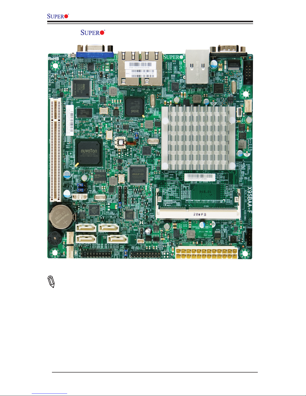
X9SBAA Motherboard Series Image
Note: All graphics and images shown in this manual were based upon the latest
PCB Revision available at the time of publishing of the manual. The motherboard
you've received may or may not look exactly the same as the image shown in
this manual.
Chapter 1: Introduction
1-3
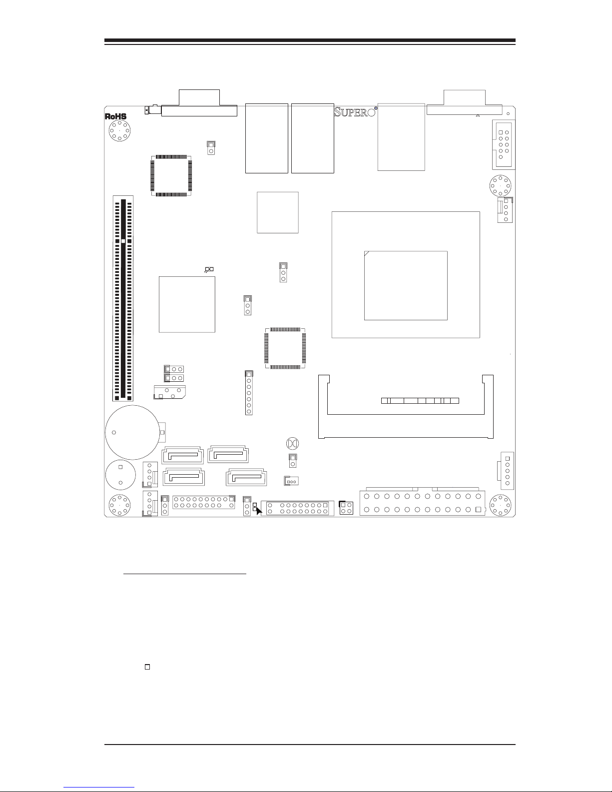
X9SBAA Motherboard Series Layout
Important Notes to the User
•Jumpers not indicated are for testing only.
•See Chapter 2 for detailed information on jumpers, I/O ports and JF1 front
panel connections.
•" " indicates the location of "Pin 1".
JPCI1
6
JBT1
1
JBAT1
SW1
DM1
A
LED3
A
C
LE1
A
C
JLAN2
JLAN1
JSD1
JDIMM1
JTPM1/P80
JD1
1
JPW1
12
SP1
JPG1
1
JPB1
1
JWP1
1
JWD1
JPL1
1
JOH1
1
JL1
1
JCOM1
JPI2C1
JCOM2
FAN1
1
1
FAN2
FAN3
JF1
7
I-SATA1
I-SATA3
I-SATA2
I-SATA0
2-3:DISABLE
JPG1:VGA
1-2:ENABLE
JBT1:
C
USB3.0 0/1
2-3:DISABLE
JPL1:LAN
1-2:ENABLE
FF
JPI2C1:PWR I2C
7
7
7
7
SLOT1 PCI 33MHz
UID
2-3:DISABLE
JPB1:BMC
1-2:ENABLE
CMOS CLEAR
1-2:RST
2-3:NMI
JWD1:WATCH DOG
OVERHEAT
JL1:
CHASSIS INTRUSION
VGA
JSD1:SATA
DOM POWER
JD1:1-3 PWR LED
4-7 SPEAKER
JTPM1:TPM/PORT80
LAN2/4
PWR LEDXNMI
HDD LED
LAN1/3
NIC1
CPU
NIC2 OH/ RSTXPWR
ON
IPMI_LAN
SODIMM1
FAN1/CPU
COM1
COM3
J22
JF2
1-4
X9SBAA Motherboard Series User's Manual
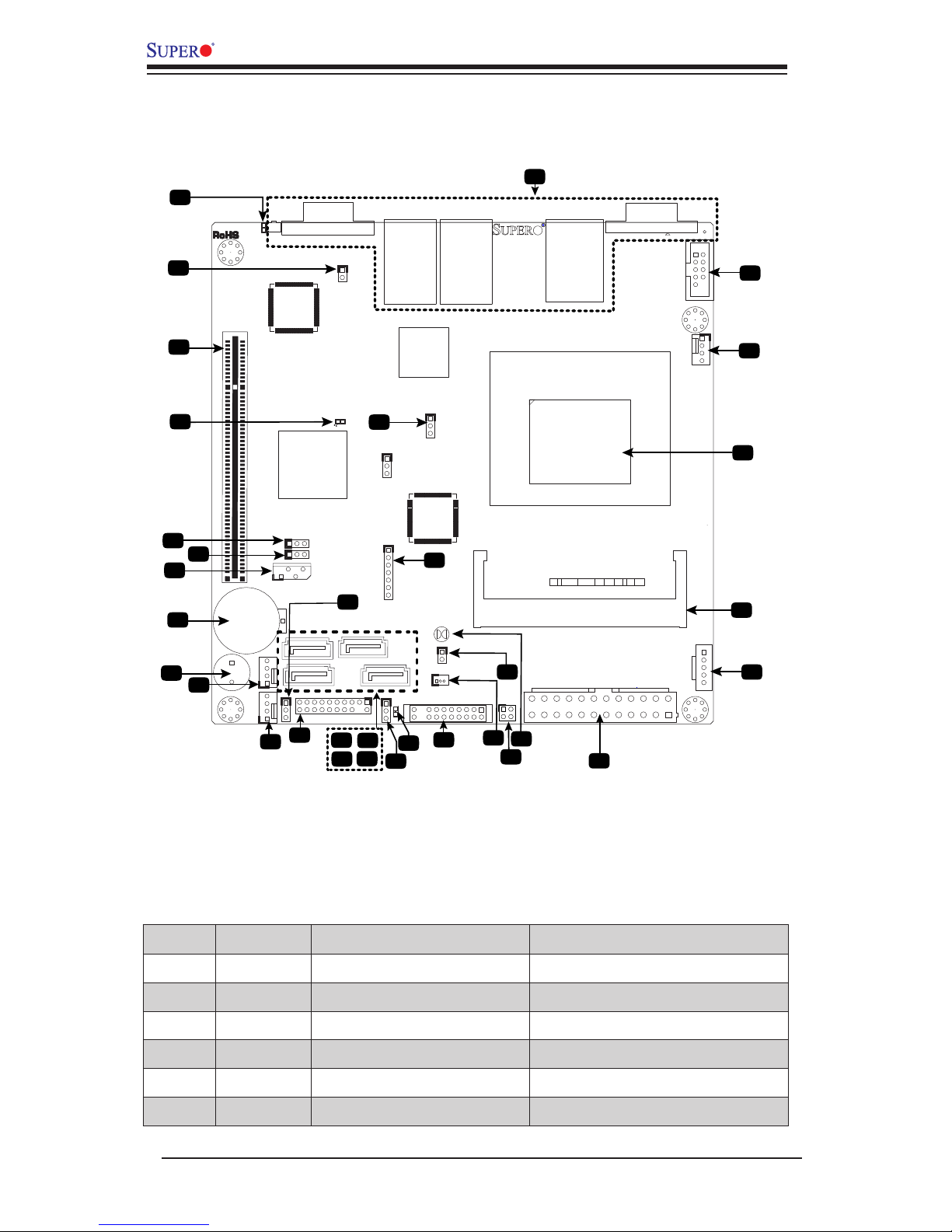
X9SBAA Motherboard Series Quick Reference
(not drawn to scale)
Jumper Descriptions
JPCI1
6
JBT1
1
JBAT1
SW1
DM1
A
LED3
A
C
LE1
A
C
JLAN2
JLAN1
JSD1
JDIMM1
JTPM1/P80
JD1
1
JPW1
12
SP1
JPG1
1
JPB1
1
JWP1
1
JWD1
JPL1
1
JOH1
1
JL1
1
JCOM1
JPI2C1
JCOM1
FAN1
1
1
FAN2
FAN3
JF1
7
I-SATA1
I-SATA3
I-SATA2
I-SATA0
2-3:DISABLE
JPG1:VGA
1-2:ENABLE
JBT1:
C
USB3.0 0/1
2-3:DISABLE
JPL1:LAN
1-2:ENABLE
FF
JPI2C1:PWR I2C
7
7
7
7
SLOT1 PCI 33MHz
UID
2-3:DISABLE
JPB1:BMC
1-2:ENABLE
CMOS CLEAR
1-2:RST
2-3:NMI
JWD1:WATCH DOG
OVERHEAT
JL1:
CHASSIS INTRUSION
VGA
JSD1:SATA
DOM POWER
JD1:1-3 PWR LED
4-7 SPEAKER
JTPM1:TPM/PORT80
LAN2/4
PWR LEDXNMI
HDD LED
LAN1/3
NIC1
CPU
NIC2 OH/ RSTXPWR
ON
IPMI_LAN
SODIMM1
FAN1/CPU
COM1
COM3
19
23
24
27
28
3
4
6
7
8
9
11
12
14
15
16
17
18
29
32
1
31
2
5
10
13
21
22
25
26
30
J22
JF2
20
33
Item # Jumper Description Default
6
JPB1* BMC Enable/Disable
1-2 (Enabled), 2-3 (Disabled)
7
JPG1* On-board VGA Enable/Disable
1-2 (Enabled), 2-3 (Disabled)
18
JWD1 Watch Dog Timer Reset 1-2 (Reset), 2-3 (NMI)
24
JBT1 CMOS Reset Short contact pads to reset CMOS
31
JPL1 LAN Enable/Disable 1-2 (Enabled), 2-3 (Disabled)
33
J22 AC On Default 1-2 (On), 2-3 (Off)
Chapter 1: Introduction
1-5
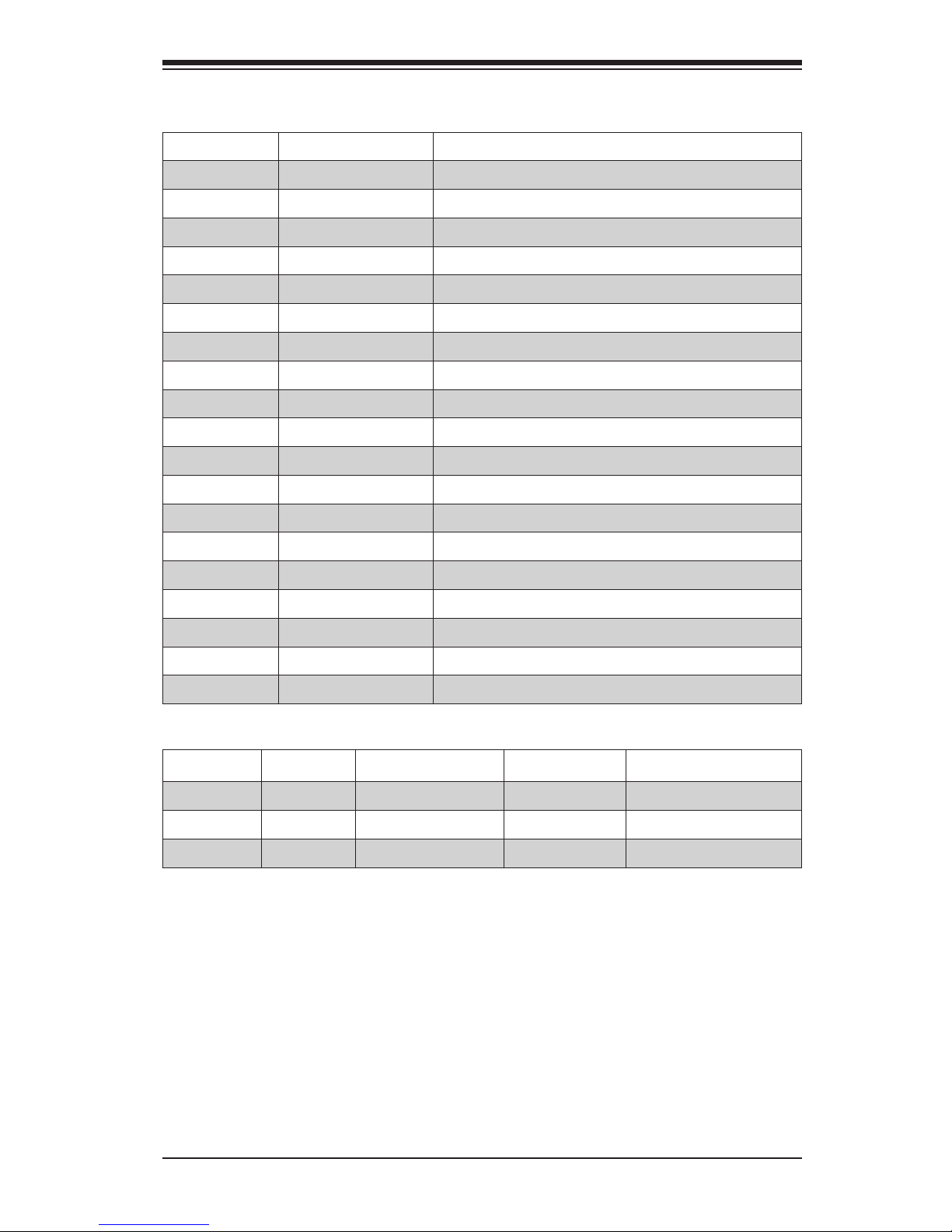
Ports, Connectors, LED Indicators
Item # LED Description Color/State Status
2
UID* Unit ID LED
Blue/Solid Unit ID switch is on
5
DM1*
IPMI Heartbeat
Green/Blinking IPMI On/Normal
19
LE1
System Power LED
Green/Solid System On/Running
Item # Connector Description
1
Back Panel I/O
See detail on page 2-6
3
JOH1 System Overheat Header
4
SLOT1 33MHz PCI Slot (Slot 1)
8
JIPMB1* 4-pin External BMC I2C Header
9
JBAT1 Internal Backup Battery
10
SP1 Internal Speaker/Buzzer
11,12,29
FAN3,2,1 System Fan Headers (FAN1=CPU Fan)
13
JTPM1 Trusted Platform Module (TPM) Header
14,15,16,17
SATA3,1,2,0 Internal SATA Ports
20
JF1 Front Panel Control Header, see detail on the right
21
JSD1 Disk-On-Module (DOM) Power Header
22
JF2 Reserved
23
JL1 Chassis Intrusion Header
25
JPW1 24-Pin ATX Power Header
26
JPI2C1 Power Supply SMBus I2C Header
27
SODIMM1 Memory Slot (SODIMM, up to 8GB)
28
CPU Intel ATOM SoC S1260, BGA1283,8.5W,2.0GHz 2C/4T
30
COM1* Internal COM1 Header
32
JD1 Pins 1-3: Power LED, Pins 4-7: Ext. Speaker Header
* X9SBAA-F Only
1-6
X9SBAA Motherboard Series User's Manual
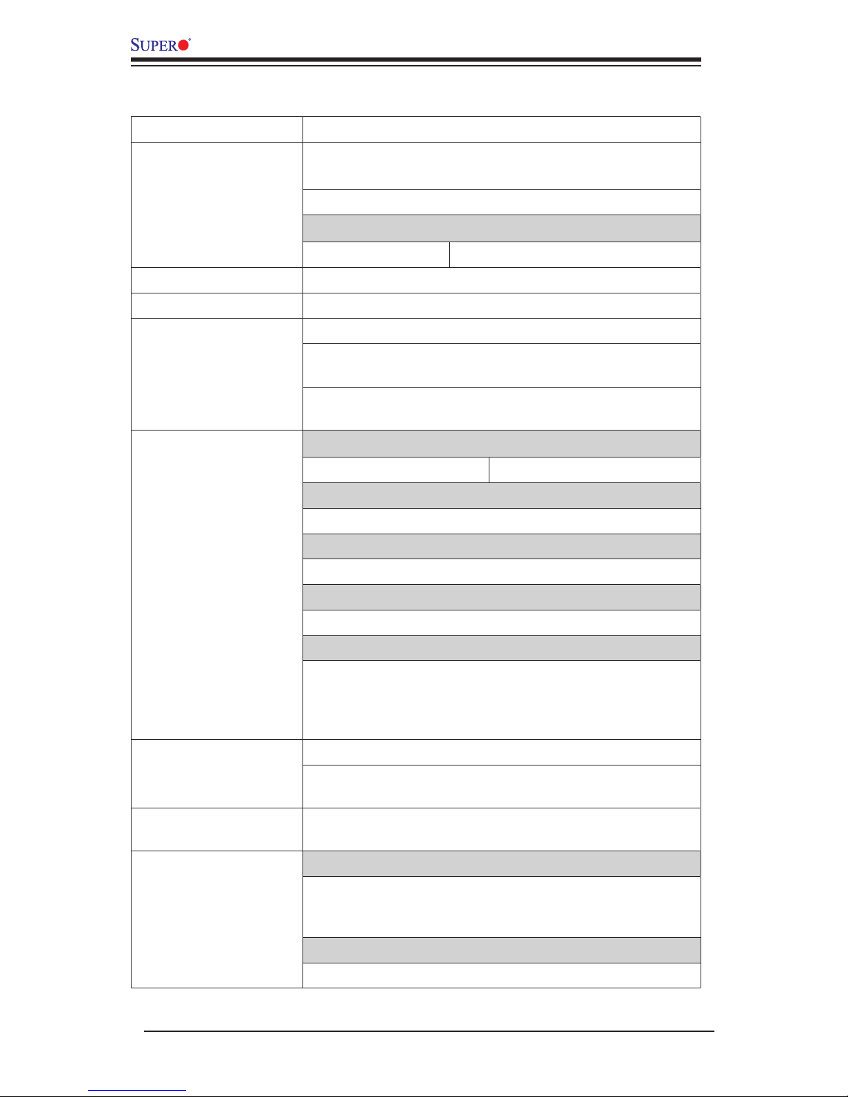
Motherboard Features
CPU Single Intel® ATOM SoC S1260,BGA1283, 8.5W
Memory One (1) 204-pin SO-DIMM slot supports up to 8GB of
DDR3, unbuffered, 1333 MHz, ECC memory only
Supports single-channel memory bus
DIMM sizes
ECC SO-DIMM 2GB, 4GB and 8GB
Expansion Slots One (1) PCI-33MHz expansion slot (3.3V only, 32-bit)
Graphics Matrox G200eW (X9SBAA-F only)
Network Connections One (1) Intel I350-AM2
Two (2) GbE RJ-45 Rear I/O panel connectors with link
and activity LEDs
One (1) IPMI RJ-45 Rear I/O panel connector with KVM
support (X9SBAA-F only)
I/O Devices SATA Connections (Marvell 88SE9230)
SATA 3.0 ports Four (4) with RAID 0/1
USB Devices (Renesas uPD720201)
Two (2) USB 3.0 ports on the back panel
VGA Graphics (Back Panel)
One (1) VGA port (X9SBAA-F only)
Keyboard/Mouse
USB keyboard/mouse support
Serial (COM) Ports
One (1) Fast 16550 UART COM port on the I/O back
panel (COM3) from S1260 as a PCI device. One (1)
COM port header (COM1) from WPCM450 (X9SBAA-F
only)
BIOS 8 MB SPI AMI BIOS® SM ash BIOS
Plug and play, APM 1.2, DMI 2.3, ACPI 4.0a, USB keyboard support and SMBIOS 2.7
Power ACPI/ACPM power management, main switch override
mechanism, keyboard wake-up from soft off.
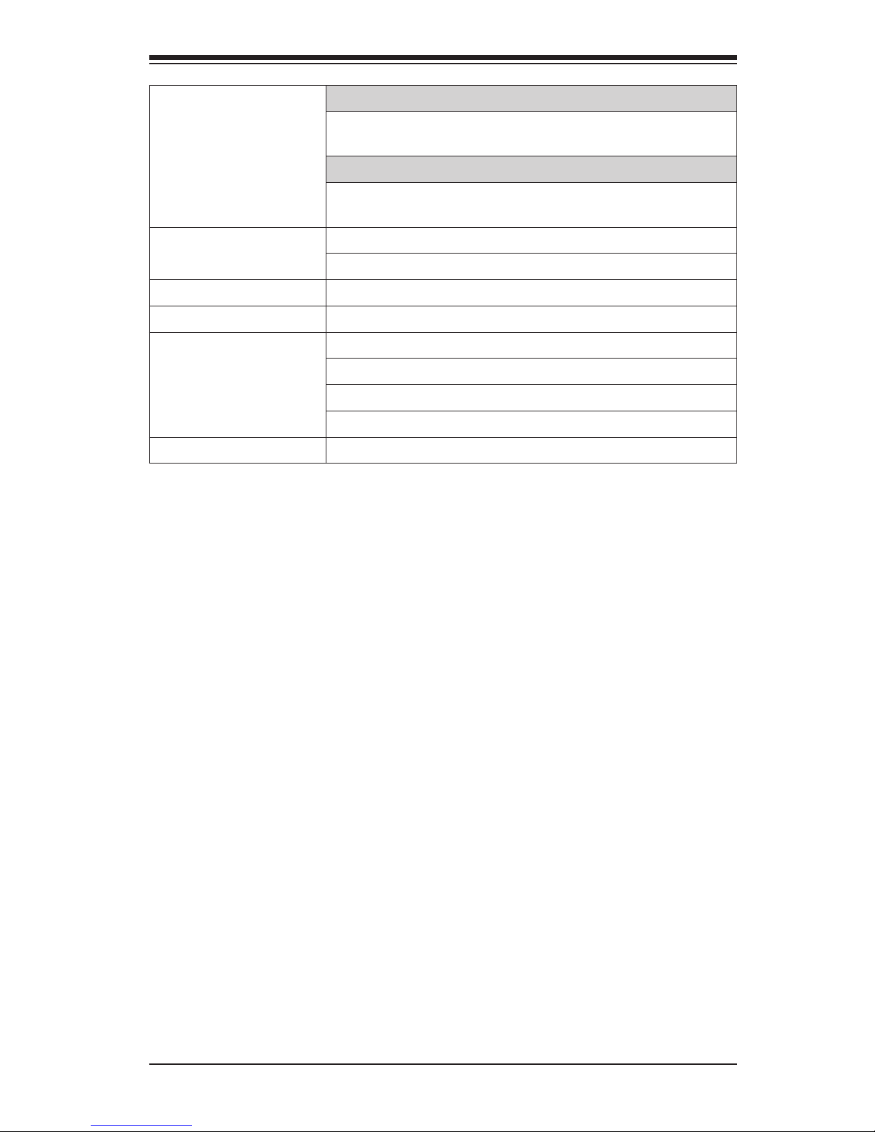
PC Health Monitoring CPU
Onboard voltage monitors for CPU Cores: +1.8V, +3.3V,
+5V, +/- 12V, +3.3V stdby, +5V stdby, VBAT, HT, memory,
chipset.
Fans
Three (3) 4-pin fan headers with tachometer monitoring
Chapter 1: Introduction
1-7
Temperature
CPU monitoring, chassis environment monitoring, CPU
thermal trip support, PC temperature sensing logic
LED
CPU/system overheat, suspend state indicator, UID/Remote UID
Utilities (Download) BIOS ash upgrade utility
Drivers and software
Compliance ROHS 6/6 (full compliance, lead free)
Security One (1) TPM header, chassis intrusion detection/header
Environment
Specications
Operating Temperature Range: 0°C ~ 60°C (32°F ~ 140°F)
Non-Operating Temperature Range: -20°C ~ 70°C (-4°F ~ 158°F)
Operating Relative Humidity Range: 10% ~ 85% (non-condensing)
Non-Operating Relative Humidity Range: 10% ~ 95% (non-condensing)
Dimensions Mini-ITX form factor (6.7" x 6.7"), 8-layers
1-8
X9SBAA Motherboard Series User's Manual
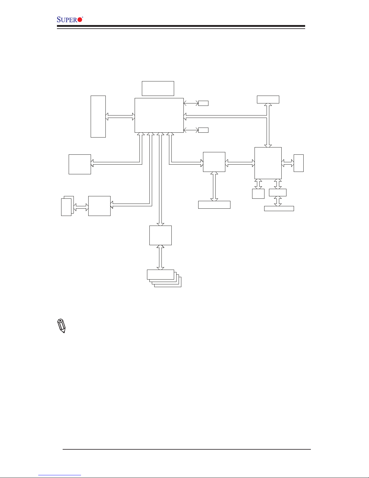
X9SBAA Motherboard Series Block Diagram
Note: This is a general block diagram. Please see the Motherboard Features pages
for details on the features of the motherboard.
SO-DIMM
ECC
Centerton
S1260
8.5W
DDR3-1333
I350
LAN
PCIe X2 G2
PEB383
PCIE BRIDGE
23ICP2G1XeICP
PCI32
PCI 32
SLOT 1
PHY
DEDICATE LAN
RTL8201
TPM HDR/P80
VGA BMC
VGA
COM 2
WPCM450
DDR II
LPC
SPI
COM 1
uPD720201
USB
PCIe X1 G2
USB 3.0
#0
#1
USB
88SE9230
SATA
PCIe X2 G2
Renesas
Marvell
SATA 3
#0
#1
#2
#3
6.0 Gb/S
#1
1 PHASE
VR12
X9SBAA/-F

Chapter 1: Introduction
1-9
1-2 PowerCongurationSettings
This section describes features of your motherboard that deal with power and
power settings.
Slow Blinking LED for Suspend-State Indicator
When the CPU goes into a suspend state, the chassis power LED will start blinking
to indicate that the CPU is in suspend mode. When the user presses any key, the
CPU will wake up and the LED will automatically stop blinking and remain on.
BIOS Support for USB Keyboard
If the USB keyboard is the only keyboard in the system, it will function like a normal
keyboard during system boot-up.
Main Switch Override Mechanism
When an ATX power supply is used, the power button can function as a system
suspend button. When the user presses the power button, the system will enter a
Soft Off state. The monitor will be suspended and the hard drive will spin down.
Pressing the power button again will cause the whole system to wake up. During the
SoftOff state, the ATX power supply provides power to keep the required circuitry
in the system "alive." In case the system malfunctions and you want to turn off the
power, just press and hold the power button for 4 seconds. The power will turn off
and no power will be provided to the motherboard.
1-3 Power Supply
As with all computer products, a stable power source is necessary for proper and
reliable operation. It is even more important for processors that have high CPU
clock rates of 1 GHz and faster.
The X9SBAA Motherboard Series accommodates 12V ATX power sup-
plies. Although most power supplies generally meet the specications required by
the CPU, some are inadequate. A 2-Amp of current supply on a 5V Standby rail is
strongly recommended.

1-10
X9SBAA Motherboard Series User's Manual
Notes

Chapter 2: Installation
2-1
Chapter 2
Installation
2-1 Static-Sensitive Devices
Electrostatic-Discharge (ESD) can damage electronic com ponents. To prevent dam-
age to your system board, it is important to handle it very carefully. The following
measures are generally sufcient to protect your equipment from ESD.
Precautions
• Use a grounded wrist strap designed to prevent static discharge.
• Touch a grounded metal object before removing the board from the antistatic
bag.
• Handle the board by its edges only; do not touch its components, peripheral
chips, memory modules or gold contacts.
• When handling chips or modules, avoid touching their pins.
• Put the motherboard and peripherals back into their antistatic bags when not in
use.
• For grounding purposes, make sure your computer chassis provides excellent
conductivity between the power supply, the case, the mounting fasteners and
the motherboard.
• Use only the correct type of onboard CMOS battery. Do not install the onboard
upside down battery to avoid possible explosion.
Unpacking
The motherboard is shipped in antistatic packaging to avoid static damage. When
unpacking the board, make sure the person handling it is static protected.
2-2
X9SBAA Motherboard Series User's Manual
2-2 Motherboard Installation
All motherboards have standard mounting holes to t different types of chassis.
Make sure that the locations of all the mounting holes for both motherboard and
chassis match. Although a chassis may have both plastic and metal mounting fas-
teners, metal ones are highly recommended because they ground the motherboard
to the chassis. Make sure that the metal standoffs click in or are screwed in tightly.
Then use a screwdriver to secure the motherboard onto the motherboard tray.
Caution: Some components are very close to the mounting holes. Please
take precautionary measures to prevent damage to these components
when installing the motherboard to the chassis.
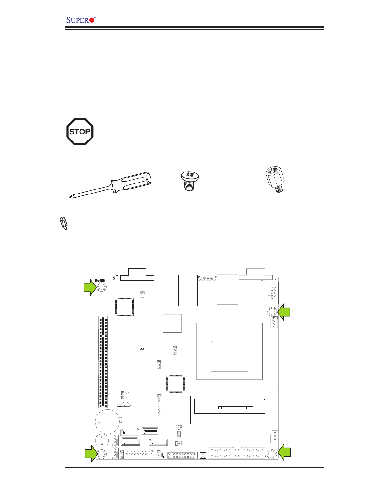
Tools Needed
Philips Screwdriver
Pan head screws (4 pieces)
Location of Mounting Holes
There are four (4) mounting holes on the X9SBAA motherboard series.
Stand Offs (4 pieces)
(Only if needed)
Note: The above items are not provided with this motherboard.
JPCI1
6
JBT1
1
JBAT1
SW1
DM1
A
LED3
A
C
LE1
A
C
JLAN2
JLAN1
JSD1
JDIMM1
JTPM1/P80
JD1
1
JPW1
12
SP1
JPG1
1
JPB1
1
JWP1
1
JWD1
JPL1
1
JOH1
1
JL1
1
JCOM1
JPI2C1
JCOM2
FAN1
1
1
FAN2
FAN3
JF1
7
I-SATA1
I-SATA3
I-SATA2
I-SATA0
2-3:DISABLE
JPG1:VGA
1-2:ENABLE
JBT1:
C
USB3.0 0/1
2-3:DISABLE
JPL1:LAN
1-2:ENABLE
FF
JPI2C1:PWR I2C
7
7
7
7
SLOT1 PCI 33MHz
UID
2-3:DISABLE
JPB1:BMC
1-2:ENABLE
CMOS CLEAR
1-2:RST
2-3:NMI
JWD1:WATCH DOG
OVERHEAT
JL1:
CHASSIS INTRUSION
VGA
JSD1:SATA
DOM POWER
JD1:1-3 PWR LED
4-7 SPEAKER
JTPM1:TPM/PORT80
LAN2/4
PWR LEDXNMI
HDD LED
LAN1/3
NIC1
CPU
NIC2 OH/ RSTXPWR
ON
IPMI_LAN
SODIMM1
FAN1/CPU
COM1
COM3
J22
JF2

Chapter 2: Installation
2-3
Installation Instructions
Install the I/O shield into the chassis.
Caution: To avoid damaging the motherboard and its components, please do not
use a force greater than 8 lb/inch on each mounting screw during motherboard
installation.
Locate the mounting holes on the motherboard. Refer to the layout on the
previous page for mounting hole locations.
Locate the matching mounting holes on the chassis. Install standoffs in the
chassis as needed. Align the mounting holes on the motherboard against the
mounting holes on the chassis.
Install the motherboard into the chassis carefully to avoid damage to mother-
board components.
Insert a Pan head #6 screw into a mounting hole on the motherboard and its
matching mounting hole on the chassis, using the Philips screwdriver.
Repeat Step 4 to insert #6 screws to all mounting holes.
I/O Shield
1
2
3
Stand Off
4
5
6
Make sure that the motherboard is securely placed on the chassis.
7
2-4
X9SBAA Motherboard Series User's Manual
Installing and Removing DIMMs
JPCI1
6
JBT1
1
JBAT1
SW1
DM1
A
LED3
A
C
LE1
A
C
JLAN2
JLAN1
JSD1
JDIMM1
JTPM1/P80
JD1
1
JPW1
12
SP1
JPG1
1
JPB1
1
JWP1
1
JWD1
JPL1
1
JOH1
1
JL1
1
JCOM1
JPI2C1
JCOM2
FAN1
1
1
FAN2
FAN3
JF1
7
I-SATA1
I-SATA3
I-SATA2
I-SATA0
2-3:DISABLE
JPG1:VGA
1-2:ENABLE
JBT1:
C
USB3.0 0/1
2-3:DISABLE
JPL1:LAN
1-2:ENABLE
FF
JPI2C1:PWR I2C
7
7
7
7
SLOT1 PCI 33MHz
UID
2-3:DISABLE
JPB1:BMC
1-2:ENABLE
CMOS CLEAR
1-2:RST
2-3:NMI
JWD1:WATCH DOG
OVERHEAT
JL1:
CHASSIS INTRUSION
VGA
JSD1:SATA
DOM POWER
JD1:1-3 PWR LED
4-7 SPEAKER
JTPM1:TPM/PORT80
LAN2/4
PWR LEDXNMI
HDD LED
LAN1/3
NIC1
CPU
NIC2 OH/ RSTXPWR
ON
IPMI_LAN
SODIMM1
FAN1/CPU
COM1
COM3
J22
JF2
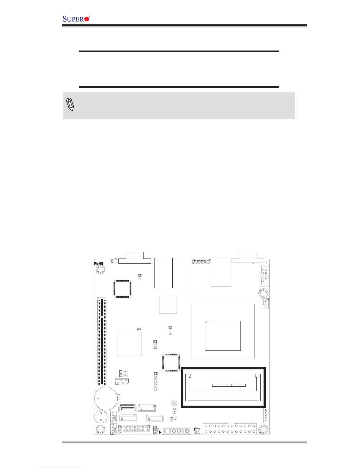
2-3 System Memory
CAUTION
Exercise extreme care when installing or removing SODIMM
modules to prevent any possible damage.
How to Install SO-DIMMs
1. The motherboard has one SO-DIMM socket. Insert the desired size of SO-
DIMM into the memory slot. Pay attention to the notch along the bottom of the
module to prevent incorrect module installation.
2. Insert the SO-DIMM module at an angle and snap it into place. See instruc-
tions on the next page.
Memory Support
The X9SBAA Motherboard Series supports up to 8GB of unbuffered ECC DDR3
1333MHz SODIMMs in one low-prole horizontal slot.
Note: Check the Supermicro website for a list of ECC-SO-DIMMs that
have been validated with the X9SBAA motherboard series.
 Loading...