


X8QB6-F
X8QBE-F
USER’S MANUAL
Revision 1.0

The information in this User’s Manual has been carefully reviewed and is believed to be accurate.
The vendor assumes no responsibility for any inaccuracies that may be contained in this document,
makes no commitment to update or to keep current the information in this manual, or to notify any
person or organization of the updates. Please Note: For the most up-to-date version of this
manual, please see our Website at www.supermicro.com.
Super Micro Computer, Inc. ("Supermicro") reserves the right to make changes to the product
described in this manual at any time and without notice. This product, including software and documentation, is the property of Supermicro and/or its licensors, and is supplied only under a license.
Any use or reproduction of this product is not allowed, except as expressly permitted by the terms
of said license.
IN NO EVENT WILL SUPER MICRO COMPUTER, INC. BE LIABLE FOR DIRECT, INDIRECT,
SPECIAL, INCIDENTAL, SPECULATIVE OR CONSEQUENTIAL DAMAGES ARISING FROM THE
USE OR INABILITY TO USE THIS PRODUCT OR DOCUMENTATION, EVEN IF ADVISED OF
THE POSSIBILITY OF SUCH DAMAGES. IN PARTICULAR, SUPER MICRO COMPUTER, INC.
SHALL NOT HAVE LIABILITY FOR ANY HARDWARE, SOFTWARE, OR DATA STORED OR USED
WITH THE PRODUCT, INCLUDING THE COSTS OF REPAIRING, REPLACING, INTEGRATING,
INSTALLING OR RECOVERING SUCH HARDWARE, SOFTWARE, OR DATA.
Any disputes arising between the manufacturer and the customer shall be governed by the laws of
Santa Clara County in the State of California, USA. The State of California, County of Santa Clara
shall be the exclusive venue for the resolution of any such disputes. Supermicro's total liability for
all claims will not exceed the price paid for the hardware product.
FCC Statement: This equipment has been tested and found to comply with the limits for a Class
A digital device pursuant to Part 15 of the FCC Rules. These limits are designed to provide
reasonable protection against harmful interference when the equipment is operated in a commercial
environment. This equipment generates, uses, and can radiate radio frequency energy and, if not
installed and used in accordance with the manufacturer’s instruction manual, may cause harmful
interference with radio communications. Operation of this equipment in a residential area is likely
to cause harmful interference, in which case you will be required to correct the interference at your
own expense.
California Best Management Practices Regulations for Perchlorate Materials: This Perchlorate
warning applies only to products containing CR (Manganese Dioxide) Lithium coin cells. “Perchlorate
Material-special handling may apply. See www.dtsc.ca.gov/hazardouswaste/perchlorate”.
WARNING: Handling of lead solder materials used in this
product may expose you to lead, a chemical known to
the State of California to cause birth defects and other
reproductive harm.
Manual Revision 1.0
Release Date: April 30, 2010
Unless you request and receive written permission from Super Micro Computer, Inc., you may not
copy any part of this document.
Information in this document is subject to change without notice. Other products and companies
referred to herein are trademarks or registered trademarks of their respective companies or mark
holders.
Copyright © 2010 by Super Micro Computer, Inc.
All rights reserved.
Printed in the United States of America

Preface
This manual is written for system integrators, PC technicians and
knowledgeable PC users. It provides information for the installation and use of the
X8QB6-F/X8QBE-F motherboard.
About This Motherboard
The X8QB6-F/X8QBE-F motherboard supports the Intel 7500 Series Socket-LS
processor, the fi rst generation chip multiprocessor (CMP) platform that offers Intel
QuickPath Interconnect (QPI) Technology, providing point-to-point system interface,
replacing the Front Side Bus. Integrating Intel Turbo Boost Technology, 45nm Process Technology, combined with support of up to 32 CPU cores and 24MB L3 cache,
the X8QB6-F/X8QBE-F motherboard substantially enhances system performance
for HPC/Cluster/Database server platforms. Please refer to our Website (http://www .
supermicro.com) for updates on supported processors. This product is intended to
be installed and serviced by professional technicians.
Preface
Manual Organization
Chapter 1 provides quick installation instructions.
Chapter 2 describes the features, specifi cations and performance of the mother-
board and provides detailed information about the chipset.
Chapter 3 provides hardware installation instructions. Read this chapter when in-
stalling the processor, memory modules and other hardware components into the
system. If you encounter any problems, see Chapter 4, which describes troubleshooting procedures for video, memory and system setup stored in the CMOS.
Chapter 5 includes an introduction to the BIOS and provides detailed information
on running the CMOS Setup utility.
Appendix A provides BIOS Error Beep Codes.
Appendix B lists Other Software Program Installation Instructions.
iii
X8QB6-F/X8QBE-F Motherboard User’s Manual
Conventions Used in the Manual
Special attention should be given to the following symbols for proper installation and
to prevent damage done to the components or injury to yourself:
Danger/Caution: Instructions to be strictly followed to prevent catastrophic
system failure or to avoid bodily injury
Warning: Important information given to ensure proper system installation
or to prevent damage to the components
Note: Additional Information given to differentiate various models or provides information for correct system setup.
iv

Contacting Supermicro
Headquarters
Address: Super Micro Computer, Inc.
980 Rock Ave.
San Jose, CA 95131 U.S.A.
Tel: +1 (408) 503-8000
Fax: +1 (408) 503-8008
Email: marketing@supermicro.com (General Information)
support@supermicro.com (Technical Support)
Website: www.supermicro.com
Europe
Address: Super Micro Computer B.V.
Preface
Het Sterrenbeeld 28, 5215 ML
's-Hertogenbosch, The Netherlands
Tel: +31 (0) 73-6400390
Fax: +31 (0) 73-6416525
Email: sales@supermicro.nl (General Information)
support@supermicro.nl (Technical Support)
rma@supermicro.nl (Customer Support)
Asia-Pacifi c
Address: Super Micro Computer, Inc.
4F, No. 232-1, Liancheng Rd.
Chung-Ho 235, Taipei County
Taiwan, R.O.C.
Tel: +886-(2) 8226-3990
Fax: +886-(2) 8226-3991
Website: www.supermicro.com.tw
Technical Support:
Email: support@supermicro.com.tw
Tel: 886-2-8228-1366, ext.132 or 139
v

X8QB6-F/X8QBE-F Motherboard User’s Manual
Table of Contents
Preface
Chapter 1 Quick Installation Guide
1-1 Installing the CPU ...........................................................................................1-1
1-2 Installing the CPU/Heatsink/ CPU Fans ......................................................... 1-1
1-3 Installing the Memory Modules .......................................................................1-2
1-4 Installing the I/O Shield ................................................................................... 1-2
1-5 Installing the Motherboard ..............................................................................1-3
1-6 Connecting the Power Supply.........................................................................1-3
1-7 Installing Internal Peripherals ..........................................................................1-4
1-8 Installing External Peripherals ........................................................................1-4
Chapter 2 Overview
2-1 Overview ......................................................................................................... 2-1
2-2 Chipset Overview ...........................................................................................2-11
2-3 Special Features ...........................................................................................2-12
2-4 PC Health Monitoring .................................................................................... 2-12
2-5 ACPI Features ...............................................................................................2-13
2-6 Power Supply ................................................................................................2-13
2-7 Super I/O ....................................................................................................... 2-14
2-8 Overview of the Nuvoton WPCM450R Controller .......................................2-14
Chapter 3 Installation
3-1 Static-Sensitive Devices ..................................................................................3-1
Precautions .....................................................................................................3-1
Unpacking .......................................................................................................3-1
3-2 Processor and Heatsink Installation................................................................3-2
Installing an LGA 1567 Processor ..................................................................3-2
Installing a Passive CPU Heatsink ................................................................. 3-4
Removing the Passive Heatsink .....................................................................3-5
3-3 Installing and Removing the Memory Modules ...............................................3-6
Installing & Removing DIMMs .........................................................................3-6
Removing Memory Modules ........................................................................... 3-6
3-4 Motherboard Installation ..................................................................................3-9
Tools Needed .................................................................................................. 3-9
Location of Mounting Holes ............................................................................ 3-9
Installing the Motherboard ............................................................................3-10
3-5 Control Panel Connectors/I/O Ports...............................................................3-11
Back Panel Connectors/I/O Ports ..................................................................3-11
Back Panel I/O Port Locations and Defi nitions ............................................3-11
vi

Table of Contents
Universal Serial Bus (USB) ...................................................................... 3-12
Serial Port ................................................................................................. 3-13
Video Connection .....................................................................................3-13
Ethernet Ports .......................................................................................... 3-14
Unit Identifi er Switch ................................................................................ 3-15
Front Control Panel ....................................................................................... 3-16
Front Control Panel Pin Defi nitions............................................................... 3-17
NMI Button ............................................................................................... 3-17
Power LED ..............................................................................................3-17
HDD LED .................................................................................................. 3-18
NIC1/NIC2 LED Indicators ....................................................................... 3-18
Overheat (OH)/Fan Fail/PWR Fail/UID LED ............................................ 3-19
Power Fail LED ........................................................................................ 3-19
Reset Button ........................................................................................... 3-20
Power Button ........................................................................................... 3-20
3-6 Connecting Cables ........................................................................................ 3-21
Power Connectors ...................................................................................3-21
Fan Headers ............................................................................................. 3-22
Chassis Intrusion .....................................................................................3-22
Internal Speaker .......................................................................................3-23
Power LED/Speaker ................................................................................. 3-23
TPM Header/Port 80 ................................................................................ 3-24
Overheat LED/Fan Fail ............................................................................3-24
Power SMB (I
2
C) Connector .................................................................... 3-25
IPMB .........................................................................................................3-25
T-SGPIO 1/2 Headers .............................................................................. 3-26
3-7 Jumper Settings ............................................................................................3-27
Explanation of Jumpers ................................................................................3-27
GLAN Enable/Disable ..............................................................................3-27
CMOS Clear ............................................................................................. 3-28
Watch Dog Enable/Disable ...................................................................... 3-28
VGA Enable .............................................................................................. 3-29
TPM Support Enable ................................................................................ 3-29
SAS2 Enable (X8QB6-F only) ..................................................................3-30
3-8 Onboard LED Indicators ...............................................................................3-31
GLAN LEDs .............................................................................................. 3-31
IPMI Dedicated LAN LEDs .......................................................................3-31
Onboard Power LED ............................................................................... 3-32
BMC Heartbeat LED ................................................................................3-32
vii

X8QB6-F/X8QBE-F Motherboard User’s Manual
Rear UID LED ......................................................................................... 3-33
3-9 Serial ATA Connections ................................................................................. 3-34
Serial ATA Ports........................................................................................ 3-34
SAS2 Ports (X8QB6-F only).....................................................................3-34
Chapter 4 Troubleshooting
4-1 Troubleshooting Procedures ...........................................................................4-1
Before Power On ............................................................................................ 4-1
No Power ........................................................................................................ 4-1
No Video ......................................................................................................... 4-2
System Boot Failure ..................................................................................... 4-2
Losing the System’s Setup Confi guration ....................................................... 4-2
Memory Errors ...............................................................................................4-3
When the System Becomes Unstable ............................................................ 4-3
4-2 Technical Support Procedures ........................................................................4-4
4-3 Frequently Asked Questions ...........................................................................4-5
4-4 Returning Merchandise for Service.................................................................4-6
Chapter 5 BIOS
5-1 Introduction ...................................................................................................... 5-1
Starting BIOS Setup Utility ..............................................................................5-1
How To Change the Confi guration Data ......................................................... 5-1
Starting the Setup Utility ................................................................................. 5-2
5-2 Main Setup ......................................................................................................5-2
5-3 Advanced Setup Confi gurations...................................................................... 5-4
5-4 PCI/PnP Confi guration ................................................................................. 5-21
5-5 Boot Confi guration ........................................................................................5-23
5-6 Security Settings ........................................................................................... 5-25
5-6 RC Settings ...................................................................................................5-26
5-7 Chipset Settings ............................................................................................ 5-28
5-8 Exit Options ................................................................................................... 5-31
Appendix A BIOS Error Beep Codes
A-1 BIOS Error Beep Codes ................................................................................. A-1
Appendix B Software Installation Instructions
B-1 Installing Software Programs ..........................................................................B-1
B-2 Confi guring Supero Doctor III .........................................................................B-2
viii
Quick Installation Guide
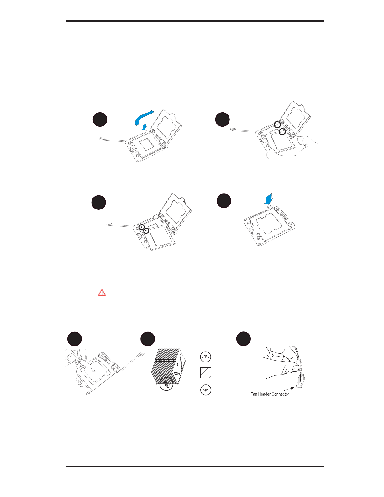
1-1 Installing the CPU
2
A B
1
Chapter 1: Quick Installation Guide
Chapter 1
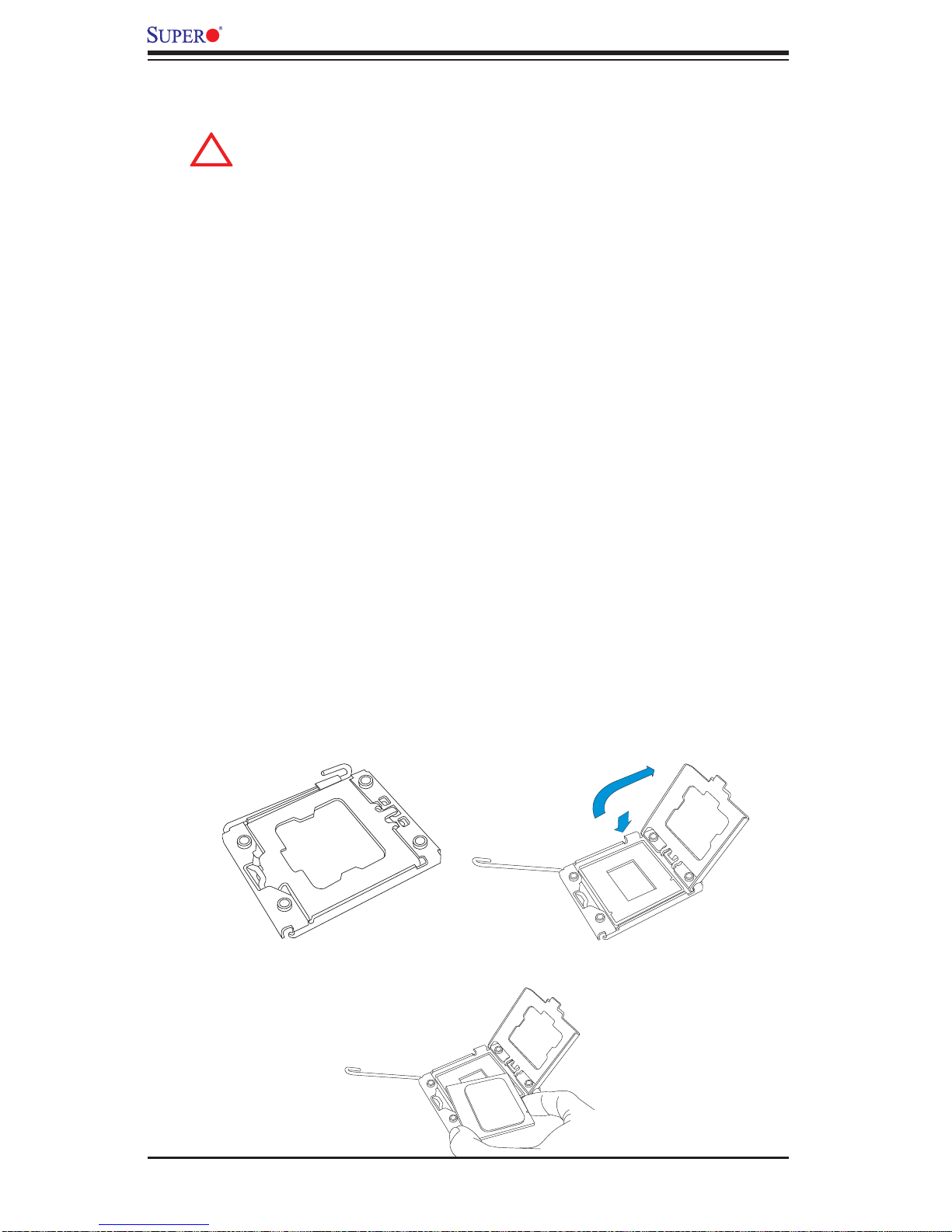
CPU Key
A. Press the socket clip down to unlock
it. Gently lift the socket clip to open the
load plate.
C
CPU Pin 1
C. Align CPU Pin 1 against Socket Pin
1. Once they are aligned, lower the CPU
down to the socket.
To avoid damage, do not rub the CPU pins against the socket.
B. Align the CPU key with the socket
key.
D
D. Once the CPU is fully seated on
the socket, press the socket clip down
to lock it.
1-2 Installing the CPU/Heatsink/ CPU Fans
A B
C
A. Apply the appropriate amount of ther-
mal grease (to 0.13mm in thickness).
B. Insert the two push-pins on the sides
of the heatsink into the mounting holes
on the motherboard, turning clockwise
to lock them.
C. Connect the fan cables to CPU
Fan1 and CPU Fan 2 headers.
1-1
X8QB6-F/X8QBE-F Motherboard User’s Manual
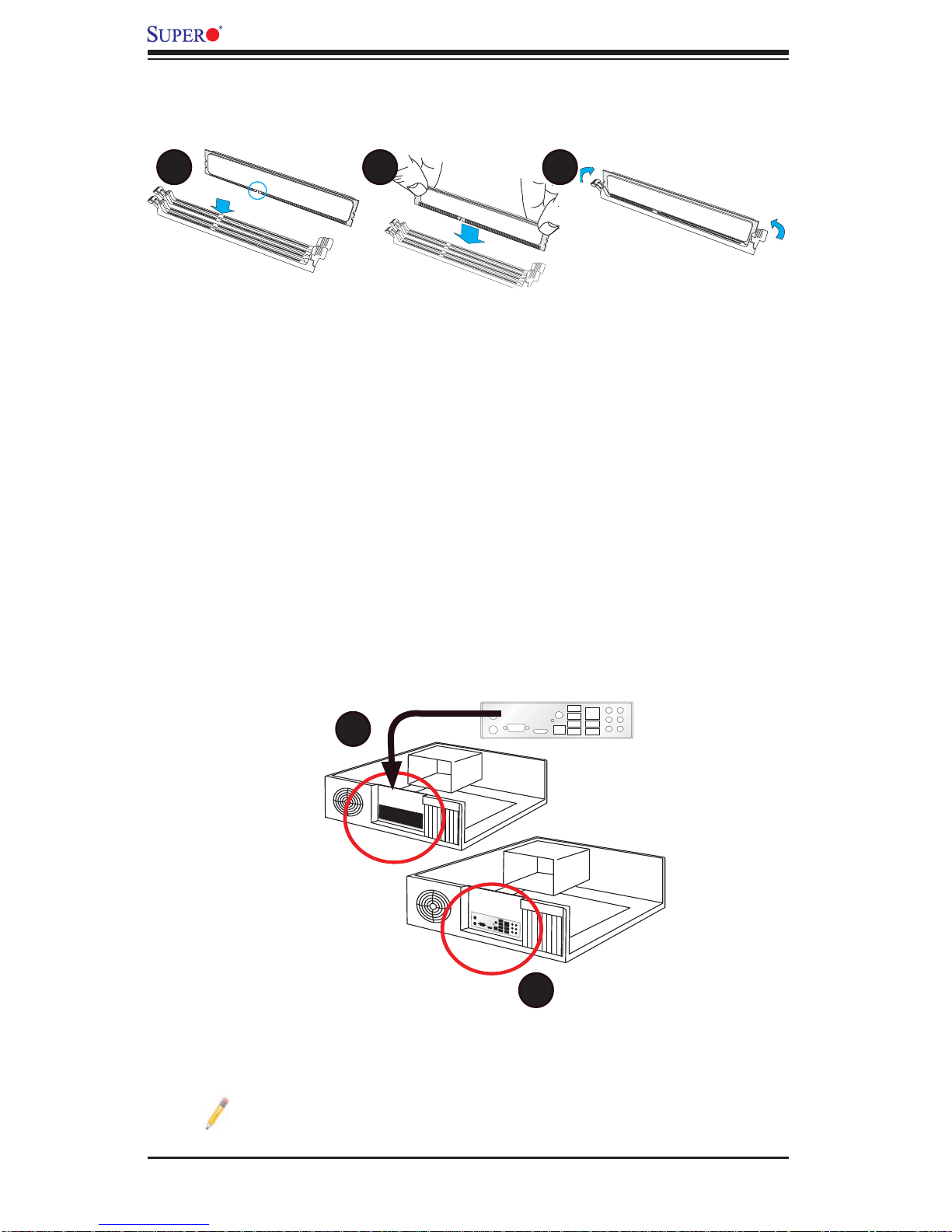
1-3 Installing the Memory Modules
A B C
A. Align the key on the DIMM module
against that of the DIMM socket.
B. Insert the DIMM module straight down
to the DIMM socket.
1-4 Installing the I/O Shield
A
C. Press the notches on the ends of
the DIMM module inwards to lock it.
Note: Chassis and I/O plate images are for illustration purposes only . They
may be different from what you have.
B
1-2
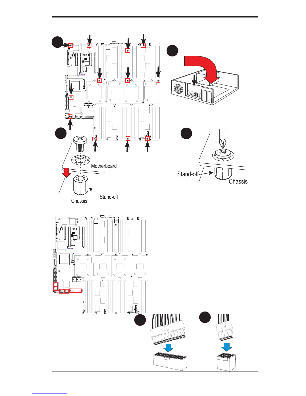
1-5 Installing the Motherboard
A
X8QB6/X8QBE
Rev.1.01a
Chapter 1: Quick Installation Guide
B
C
1-6 Connecting the Power Supply
X8QB6/X8QBE
Rev.1.01a
D
A
B
1-3
X8QB6-F/X8QBE-F Motherboard User’s Manual
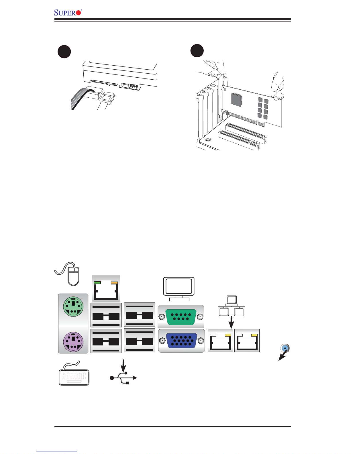
1-7 Installing Internal Peripherals
A
SATA/SAS2 Drives
B
Add-on Cards
1-8 Installing External Peripherals
Serial Port
Mouse
Keyboard
IPMI LAN
USB 2/3
(COM1)
VGA Port LAN 1/2 PortsUSB 0/1
UID
Switch
1-4

Chapter 2: Overview
Chapter 2
Overview
2-1 Overview
Checklist
Congratulations on purchasing your computer motherboard from an acknowledged
leader in the industry. Supermicro boards are designed with the utmost attention to
detail to provide you with the highest standards in quality and performance.
Please check that the following items have all been included with your motherboard.
If anything listed here is damaged or missing, contact your retailer.
The following items are included in the retail box.
One (1) Supermicro Mainboard
•
Six (6) Serial ATA cables (CBL-0044Lx6) (for X8QBE-F)•
Two (2) I-Pass to 4 Serial ATA (50-cm) cables (CBL-097L-02) (for X8QB6-F)•
One (1) Supermicro CD containing drivers and utilities•
One (1) User's/BIOS Manual (MNL#1178)•
2-1
X8QB6-F/X8QBE-F Motherboard User’s Manual
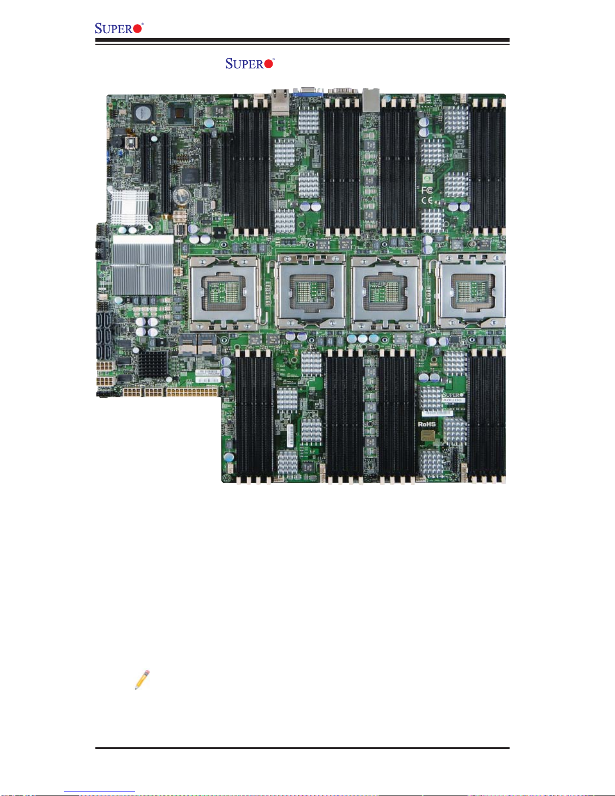
Motherboard Image
Note: All graphics shown in this manual were based upon the latest PCB
Revision available at the time of publishing of the manual. The motherboard
you've received may or may not look exactly the same as the graphics
shown in this manual.
2-2
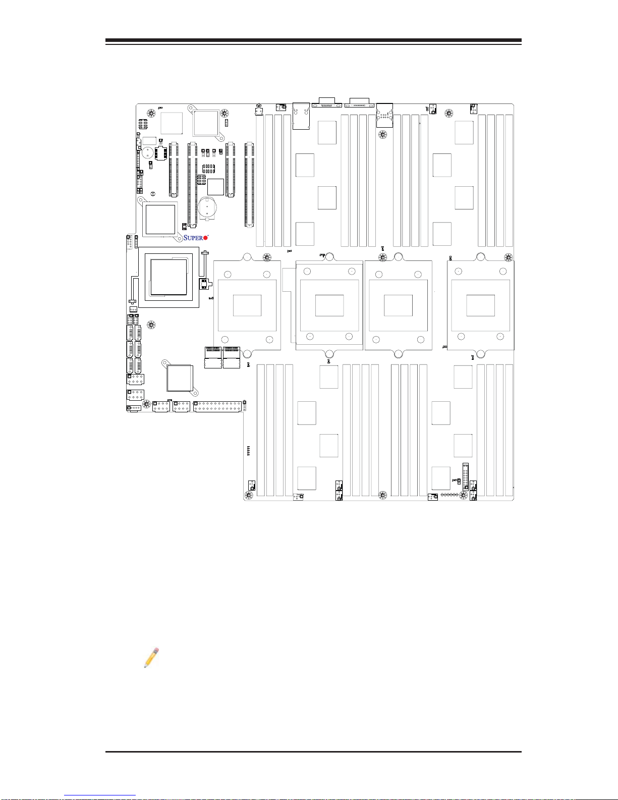
Motherboard Layout
Chapter 2: Overview
JWOR
IPMB
JD1
JWD1
JLPC1
USB2/3
T-SGPIO1
I-SATA0
I-SATA2
I-SATA4
JPW4
JPI2C
SP1
JL1
PORT80
USB5
FAN11
T-SGPIO2
I-SATA1
I-SATA3
I-SATA5
JPW5
D10
BMC_HB
Winbond
BMC CTRL
BMCRST
JPRST1
BMC
Firmware
JBT1
Intel ICH10R
Intel
IOH 7500
LED35
JPW2
Intel 82576
LAN CTRL
Slot2 PCI-E 2.0 x8
Slot3 PCI-E 2.0 x16/x8
JP1
Battery
BIOS
BIOS
Debug
LED12
PVIOP12
LSI 2108
SAS CTRL
JPW1
JPL1
JPG1
JPS1
JPT1
Slot5 PCI-E 2.0 X8
JUID_OW1
JP3
BT2
+
X8QB6/X8QBE
Rev.1.01a
SAS0~3
SAS4~7
JPW3
LED26
UID_LED
UID_SWITCH
Slot6 PCI-E 2.0 x16/X8
P1-DIMM4A
CPU1
LED18
SAS_DBG1
P2-DIMM8A
FAN10
P1-DIMM2A
P1-DIMM3A
P1-DIMM1A
LED14
P2-DIMM7A
P2-DIMM6A
(Bottom)
LAN1
LAN2
(Top)
P2-DIMM5A
VGA
LED19
CPU2
LED15
COM1
P1-DIMM5A
P1-DIMM7A
P1-DIMM6A
P2-DIMM1A
P2-DIMM2A
USB0/1
IPMI_LAN
P1-DIMM8A
P2-DIMM3A
P2-DIMM4A
LED16
CPU3
P3-DIMM4A
P3-DIMM3A
P4-DIMM8A
P4-DIMM7A
LED24
FAN9
P3-DIMM1A
P3-DIMM2A
P4-DIMM5A
P4-DIMM6A
LED20
LED21
FAN8
LED17
P3-DIMM6A
P3-DIMM5A
CPU4
P4-DIMM2A
P4-DIMM1A
P3-DIMM7A
P3-DIMM8A
P4-DIMM3A
P4-DIMM4A
LED5
LED7
LED8
P5V_STBY
LED9
LED6
FAN7
FAN6
FAN4
FAN5
FAN3
OHLED
LED23
JOH1
JF1
FAN1
FAN2
Note: SAS2 connections and the LSI 2108 SAS2 Controller are available
on the X8QB6-F only.
2-3
X8QB6-F/X8QBE-F Motherboard User’s Manual
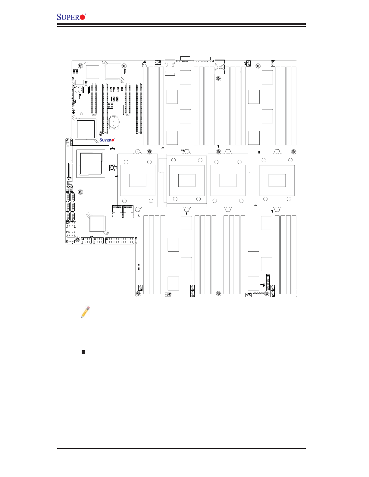
X8QB6-F/X8QBE-F Quick Reference
JWOR
IPMB
JLPC1
USB2/3
T-SGPIO1
I-SATA0
I-SATA2
I-SATA4
JPW4
JPI2C
JD1
JWD1
FAN11
SP1
JL1
PORT80
Intel ICH10R
USB5
T-SGPIO2
I-SATA1
I-SATA3
I-SATA5
JPW5
D10
BMCRST
JPRST1
BMC
Firmware
JBT1
Intel
IOH 7500
JPW2
BMC_HB
BMC CTRL
Winbond
Slot2 PCI-E 2.0 x8
BIOS
LSI 2108
SAS CTRL
LED35
JPW1
Intel 82576
LAN CTRL
Slot3 PCI-E 2.0 x16/x8
JPL1
JPG1
JPS1
JPT1
Slot5 PCI-E 2.0 X8
JUID_OW1
JP3
JP1
BT2
Battery
+
X8QB6/X8QBE
Rev.1.01a
BIOS
Debug
LED12
PVIOP12
SAS0~3
SAS4~7
JPW3
UID_LED
UID_SWITCH
Slot6 PCI-E 2.0 x16/X8
P1-DIMM4A
CPU1
LED18
SAS_DBG1
P2-DIMM8A
LED26
P1-DIMM3A
P2-DIMM7A
FAN10
P1-DIMM2A
P1-DIMM1A
LED14
P2-DIMM6A
(Bottom)
LAN1
LAN2
(Top)
P2-DIMM5A
VGA
LED19
CPU2
LED15
COM1
P1-DIMM5A
P1-DIMM7A
P1-DIMM6A
P2-DIMM1A
P2-DIMM2A
USB0/1
IPMI_LAN
P1-DIMM8A
P2-DIMM3A
P2-DIMM4A
LED16
CPU3
P3-DIMM4A
P3-DIMM3A
P4-DIMM8A
P4-DIMM7A
LED24
FAN9
P3-DIMM1A
P3-DIMM2A
P4-DIMM5A
P4-DIMM6A
LED20
LED21
FAN8
LED17
P3-DIMM6A
P3-DIMM5A
CPU4
P4-DIMM2A
P4-DIMM1A
P3-DIMM7A
P3-DIMM8A
P4-DIMM3A
P4-DIMM4A
LED5
LED7
LED8
P5V_STBY
LED9
LED6
FAN7
FAN6
FAN4
FAN5
FAN3
OHLED
LED23
JOH1
JF1
FAN1
FAN2
Notes:
See Chapter 3 for detailed information on jumpers, I/O ports and JF1 front
•
panel connections.
" " indicates the location of "Pin 1".
•
Jumpers not indicated are for testing only. •
When LED 8 (Onboard Power LED Indicator) is on, system power is on. Unplug •
the power cable before installing or removing any components.
The LSI SAS2 Controller and SAS2 Connections are available on the X8QB6-F
•
only.
LED Indicators that are not documented are for testing only.
•
2-4

Chapter 2: Overview
X8QB6-F/X8QBE-F Jumpers
Jumper
JBT1
Description Default Setting
Clear CMOS See Chapter 3
JPG1 VGA Enabled Pins 1-2 (Enabled)
JPL1 GLAN1/GLAN2 Enable Pins 1-2 (Enabled)
JPS1 (X8QB6-F only) SAS2 Enabled Pins 1-2 (Enabled)
JPT1 TPM Enabled Pins 1-2 (Enabled)
JWD1 Watch Dog Pins 1-2 (Reset)
X8QB6-F/X8QBE-F Connectors
Connectors Description
BT2 Onboard Battery (See Chpt. 4 for Used Battery Disposal)
COM1 COM1 Serial Connection
FAN 1~10 CPU//System Fan Header
(Fan 11: Reserved)
IPMB 4-pin External BMC I
2
C Header (for an IPMI Card)
I-SATA 0~5 Intel SB SATA Connectors 0~5
JD1 Speaker/Power LED Indicator
JF1 Front Panel Control Header
JL1 Chassis Intrusion
JLPC1 Port 80
JOH1 Overheat/Fan Fail LED
2
JPI
C Power Supply SMBbus I2C Header
JPW1~2, JP4~5 12V 8-Pin Power Connectors (See Warning on Pg. 2-6.)
JPW3 ATX 24-Pin Power Connector (See Warning on Pg. 2-6.)
JUID_OW1 UID Override Header
JWOR Wake-On-Ring
LAN1/LAN2 G-bit Ethernet Ports 1/2
(IPMI) LAN IPMI_Dedicated LAN
SP1 Onboard Buzzer (Internal Speaker)
Slot2, Slot5 PCI-Express 2.0 x8
Slot3, Slot6 PCI-Express 2.0 x16/x8
TPM/Port 80 Trusted Platform Module/Port 80 Header
T-SGPIO 1/2 Serial_Link General Purpose I/O Headers
USB 0/1 Back Panel USB 0/1
USB 2/3, 5 Front Panel Accessible USB Connections
UID Switch UID (Universal Identifi er) Switch
2-5
X8QB6-F/X8QBE-F Motherboard User’s Manual
VGA Backpanel VGA Port
X8QB6-F/X8QBE-F LED Indicators
LED Description State Status
D10 BMC Heartbeat LED Green: Blinking Normal
LED 8 Stand by PWR LED Green: On SB Power On
LED 26 UID LED
Blue: On (Windows OS),
Blinking (Linux)
Unit Identifi ed
Warning!
To prevent damage to the power supply or motherboard, please use a power
•
supply that contains a 24-pin and two 8-pin power connectors. Be sure to connect
these connectors to the 24-pin (JPW3) and the four 8-pin (JPW1~2,JPW4~5)
power connectors on the motherboard. Failure in doing so will void the manufacturer warranty on your power supply and motherboard.
2-6
Motherboard Features
Chapter 2: Overview
CPU
Memory
Four Intel•
cessors; each processor supports four full-width Intel
QuickPath Interconnect (QPI) links (with support of
up to 25.6 GT/s per QPI link and with Data Transfer
Rate of up to 6.4 GT/s per direction)
Integrated memory controller supports:•
32 240-pin DDR3-1066 RDIMMs running at speeds 1.
of 1066/978/800 MHz (via an onboard buffer)
Support for up to 256 GB of Registered ECC 2.
DDR3 memory in two-channel memory bus
DIMM sizes
RDIMM
• 1 GB, 2GB, 4GB, and 8GB
Virtualization: VT-x, VT-d, and VT-c
•
I/O: Intel® QuickData Technology with Intel 82576 •
LAN Controller, supports:
Intel 825761.
®
7500 Series (Socket LS-LGA 1567) pro-
Chipset
Expansion
Slots
Graphics
Network
I/O Devices
LSI 2108 (Hardware RAID w/Battery Backup)2.
Intel® 7500 Chipset (7500 IOH & ICH10R)•
Two (2) PCI Express 2.0 x16 slots (Slot3, Slot6), or•
Four (4) PCI Express2.0 x8 (Slot2, Slot5, Slot3, •
Slot6)
Winbond BMC Video Controller (Matrox G200eW)•
One Intel 82576 Gigabit (10/100/1000 Mb/s) Ethernet •
Dual-Channel Controller for LAN 1/LAN 2 ports.
Winbond WP450R Base-board Controller (BMC)
•
supports IPMI_LAN 2.0
SATA Connections
SATA Ports
• Six (6)
RAID (Win-
•
dows)
RAID (Linux)
• RAID 0, 1, 10
SAS2 Connections
RAID 0, 1, 5, 10
LSI SAS2 2108 Controller
•
SAS2 Ports• 0~3, 4~7
RAID Support
• RAID 0, 1, 5, 6, 10, 50, 60
2-7
X8QB6-F/X8QBE-F Motherboard User’s Manual
Integrated IPMI 2.0
IPMI 2.0 supported by the WPCM450R BMC
•
Serial (COM) Port
One (1) Fast UART 16550 Connection: 9-pin RS-
•
232 port
Super I/O
Winbond Super I/O 83527
•
Peripheral
Devices
BIOS
Power
Confi g.
PC Health
Monitoring
USB Devices
Two (2) USB ports on the rear I/O panel (USB 0/1)
•
One (1) USB connection for front access (USB 5)•
One (1) Type A internal connector (USB 2/3)•
64 Mb SPI AMI BIOS•
APM 1.2, PCI 2.3, ACPI 1.0/2.0/3.0, USB Keyboard,
•
Plug & Play (PnP) and SMBIOS 2.5
ACPI/ACPM Power Management•
Main switch override mechanism•
Keyboard Wake-up from Soft-Off•
Power-on mode for AC power recovery•
CPU Monitoring
Onboard voltage monitors for CPU1 Vcore, CPU2 •
Vcore, CPU3 Vcore, CPU4 Vcore, NIC Vcore, BMC
Vcore, AUX Vcore, Standby ME Vcore, 12V Scale,
1.5V, 3.3V Vcc(V), 3.3VSB, Battery Voltage, and
IOPV12.
®
SM Flash BIOS
System
Management
CPU 7-Phase switching voltage regulator
•
CPU/System overheat LED and control•
CPU Thermal Trip support•
Thermal Monitor 2 (TM2) support•
Fan Control
Fan status monitoring with fi rmware 4-pin (Pulse
•
Width Modulation) fan speed control
Low noise fan speed control
•
PECI (Platform Environment Confi guration Interface) •
2.0 support
System resource alert via Supero Doctor III
•
SuperoDoctor III, Watch Dog, NMI•
Chassis Intrusion Header and Detection•
2-8

Chapter 2: Overview
Dimensions
Note: For IPMI Confi guration Instructions, please refer to the Embedded
IPMI Confi guration User's Guide available @ http://www.supermicro.com/
support/manuals/.
16.79" (L) x 16.00" (W) (324.87 mm x 406.40 mm)•
2-9
X8QB6-F/X8QBE-F Motherboard User’s Manual
DDR3 800/1066
DDR3 800/1066
(x2)
Mill Brook
(x2)
Mill Brook
DDR3 800/1066
DDR3 800/1066
(x2)
(x2)
(x2)
DDR3 800/1066
Mill Brook
(x2)
DDR3 800/1066
Mill Brook
(x2)
SMI
6.4GT/s
DDR3 800/1066
Mill Brook
SMI 6.4GT/s
Mill Brook
SMI 6.4GT/s
SMI 6.4GT/s
(x2)
SMI
6.4GT/s
DDR3 800/1066
Mill Brook
SMI 6.4GT/s
Mill Brook
SMI 6.4GT/s
SMI 6.4GT/s
Slot2 PCIE-G2x8
Slot3 PCIE-G2x16
Slot5 PCIE-G2x8
Slot6 PCIE-G2x16
SAS x4
SAS x4
FBD0
FBD1
FBD2
FBD3
FBD0
FBD1
FBD2
FBD3
PCIE-G2x8
PCIE-G2x8x2
PCIE-G2x8
PCIE-G2x8x2
USB
Ports x4
I
P
6
Q
Q
Processor 4
P
I
6
.
4
G
T
/
QPI 6.4GT/s
QPI 6.4GT/s
Processor 3
LSI 2018
SAS CTRL
BIOS
SPI
USB 2.0
Processor 2
T
/
s
.
4
G
s
/
T
G
4
.
s
6
I
P
Q
Processor 1
QPI 6.4GT/s
QPI#0 QPI#1
Link
ICH10
SIO W83527HG
FBD0
FBD1
FBD2
FBD3
QPI 6.4GT/s
FBD0
FBD1
FBD2
FBD3
Boxboro
IOH#1
PCIE
LPC
6.4GT/s
SMI
SMI
SMI
QPI 6.4GT/s
SMI
6.4GT/s
SMI
SMI
SMI
Reset,
PWR,
GPIO
SMI
6.4GT/s
6.4GT/s
6.4GT/s
6.4GT/s
6.4GT/s
PCIE1.0x4
PCI
USB 1.0
USB 2.0
LPC
(x2)
DDR3 800/1066
Mill Brook
6.4GT/s
Mill Brook
Kawela Dual GLAN
Mill Brook
(x2)
DDR3 800/1066
Mill Brook
RMII PHY
WPCM450R
Winbond BMC
(w/Video, KVM,
SIO, Fan Speed
CTRL, PECI,
CTRL
Voltage Monitoring)
Fan CTRL
Serial
Fans
(x10)
Port
DDR3 800/1066
DDR3 800/1066
(x2)
(x2)
(x2)
DDR3 800/1066
Mill Brook
(x2)
DDR3 800/1066
Mill Brook
GLAN
GLAN
RMII
DDR2
SPI
SMBus
HM
W83795G
(x2)
DDR3 800/1066
Mill Brook
(x2)
DDR3 800/1066
Mill Brook
RJ45
10/100LAN
PHY
10/100
Rear
Video
Video
Memory
BMC
FW
Flash
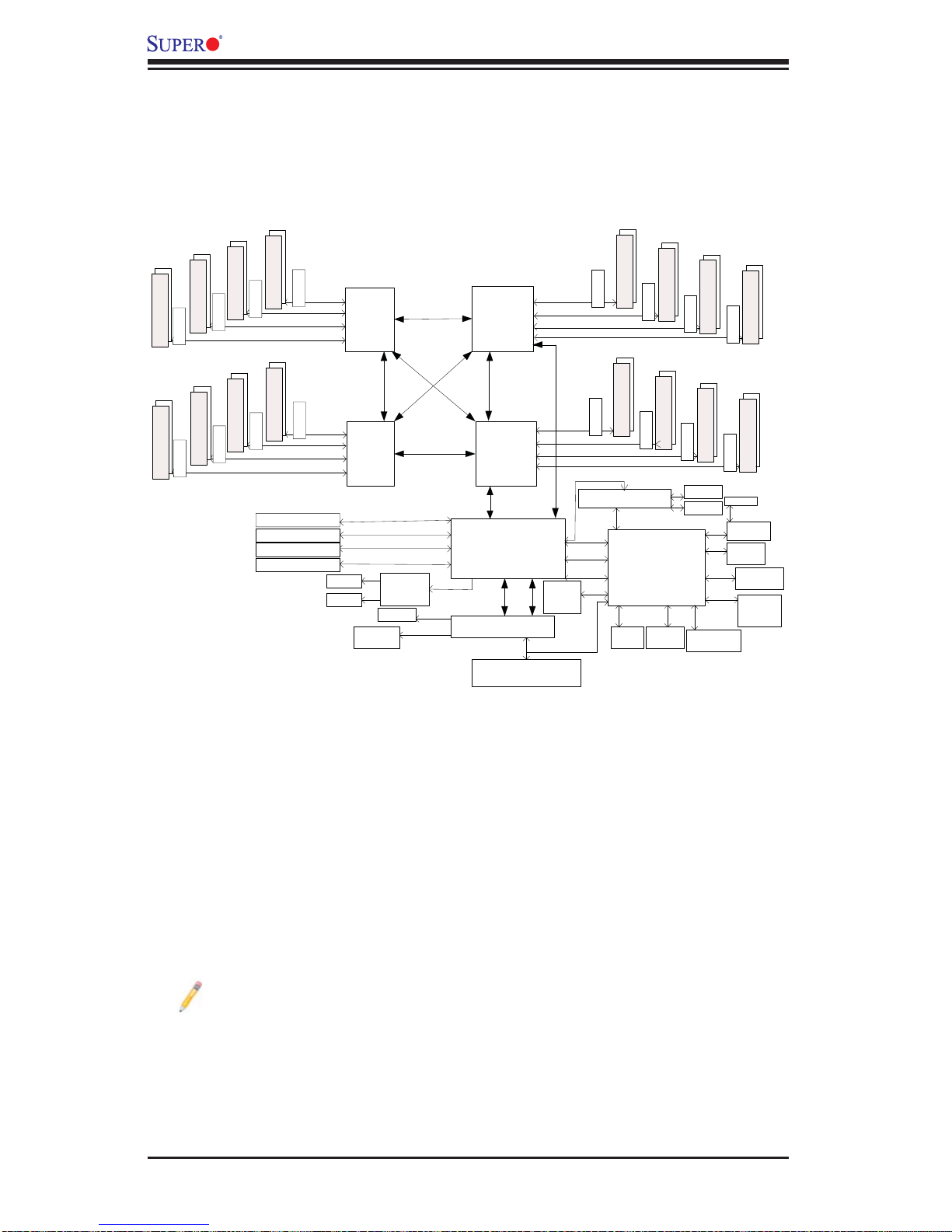
Note: This is a general block diagram and may not exactly represent the
features on your motherboard. See the Motherboard Features pages for
the actual specifi cations of each motherboard.
System Block Diagram
2-10

Chapter 2: Overview
2-2 Chipset Overview
Built upon the functionality and the capability of the Intel 7500 platform, the
X8QB6-F/X8QBE-F motherboard provides the performance and support for quartprocessor-based HPC/Cluster/Database servers. The 7500 platform consists of the
7500 Se ries Soc ket-LS (LGA 1567) pr ocess or, the 7500 (IOH), an d the ICH10R
(South Bridge).
With the Intel QuickPath interconnect (QPI) controller built in, the 7500 Series
processor is the fi rst generation chip multiprocessor (CMP) platform that offers
point-to-point system interconnect interface, greatly enhancing system performance by ut ilizing ser ial link interco nnection s, allowing for i ncreased ba ndwidth
and scalability.
The IOH provides the interface between QPI-based processor, and industrystandard PCI-Express components. Each processor supports four full-width,
bidirectional interconnects that run at the speed of 4.8 GT/s, 5.86 GT/s or 6.4
GT/s. Each QPI link consists of 20 pairs of unidirectional differential lanes for data
transmission in addition to a differential forwarded clock. The two x16 PCI Express
Gen 2 connections can also be confi gured as x8 and x4 links to comply with PCI-E
Base Specifi cation, Rev. 2.0. These PCI-E Gen 2 lanes supports peer-to-peer read
and wr ite tran sact ions. In a dditi on, the l egacy I OH prov ides a x4 ESI ( Enterpr ise
South Br idg e Inter face) link sup por t for th e legac y brid ge.
The 7500 chipset also offers a wide range of ESI, Intel® I/OAT Gen 3, Intel
VT-d an d RAS (Reliabi lity, Availabili ty and Ser viceabilit y) suppor t. The feature s
suppor ted includ e memory inte rface ECC, x4/ x8 Single Devic e Data Cor rection
(SDDC), Flow-through CRC (Cyclic Redundancy Check), parity protection, outof-ba nd registe r acces s via SM Bus, memo ry mir rorin g, and Hot- plug supp ort o n
the PCI - Expr ess Inter f ace.
Main Features of the 7500 Platform
Fully-connectivity (with four Intel® QuickPath Interconnects and up to eight cores •
in each socket with 24MB of shared last level (L3) cache supported)
CPU-Integrated memory controller with support of DDR-3 1066 MHz RDIMMS
•
running at 800/978/1066 MHz via a memory buffer
Virtualization Technology, Integrated Manageability Engine (ME) supported
•
44 bits physical address and 48 bits virtual address supported•
2-11

X8QB6-F/X8QBE-F Motherboard User’s Manual
2-3 Special Features
Recovery from AC Power Loss
The Basic I/O System (BIOS) provides a setting for you to determine how the
system will respond when AC power is lost and then restored to the system. You
can choose for the system to remain powered off (in which case you must press
the power switch to turn it back on), or for it to automatically return to a power- on
state. See the Advanced BIOS Setup section to change this setting. The default
setting is Last State.
2-4 PC Health Monitoring
This section describes the PC health monitoring features of the motherboard. All
have an onboard System Hardware Monitor chip that supports PC health monitoring.
An onboard voltage monitor will scan these onboard voltages continuously:CPU1
Vcore, CPU2 Vcore, CPU3 Vcore, CPU4 Vcore, NIC Vcore, BMC Vcore, AUX Vcore,
Standby ME Vcore, 12V Scale, 1.5V, 3.3V Vcc(V), 3.3VSB, Battery Voltage, and
IOPV12. Once a voltage becomes unstable, a warning is given or an error message is sent to the screen. The user can adjust the voltage thresholds to defi ne the
sensitivity of the voltage monitor.
Fan Status Monitor with Firmware Control
The PC health monitor can check the RPM status of the cooling fans. The onboard
CPU and chassis fans are controlled by Thermal Management via BIOS (under the
Hardware Monitoring section in the Advanced Setting).
Environmental Temperature Control
The thermal control sensor monitors the CPU temperature in real time and will turn
on the thermal control fan whenever the CPU temperature exceeds a user-defi ned
threshold. The overheat circuitry runs independently from the CPU. Once it detects
that the CPU temperature is too high, it will automatically turn on the thermal fan
control to prevent the CPU from overheating. The onboard chassis thermal circuitry
can monitor the overall system temperature and alert the user when the chassis
temperature is too high.
Note: To avoid possible system overheating, please be sure to provide
adequate airfl ow to your system.
2-12

Chapter 2: Overview
System Resource Alert
This feature is available when used with Supero Doctor III in the Windows OS
environment or used with Supero Doctor II in Linux. Supero Doctor is used to
notif y the user of cer tain system events. For example, you can also confi gure
Supero Doctor to provide you with warnings when the system temperature, CPU
temperat ures, volt ages a nd fan spe eds go beyon d a predefi ned range.
2-5 ACPI Features
ACPI stands for Advanced Confi guration and Power Interface. The ACPI specifi ca-
tion defi nes a fl exible and abstract hardware interface that provides a standard
way to integrate power management features throughout a PC system, including
its hardware, operating system and application software. This enables the system
to automatically turn on and off peripherals such as CD-ROMs, network cards, hard
disk drives and printers.
In addition to enabling operating system-directed power management, ACPI also
provides a generic system event mechanism for Plug and Play and an operating
system-independent interface for confi guration control. ACPI leverages the Plug and
Play BIOS data structures, while providing a processor architecture-independent
implementation that is compatible with Windows XP, Windows Vista and Windows
2008 Operating Systems.
Slow Blinking LED for Suspend-State Indicator
When the CPU goes into a suspend state, the chassis power LED will start blinking
to indicate that the CPU is in suspend mode. When the user presses any key, the
CPU will "wake up" and the LED will automatically stop blinking and remain on.
2-6 Power Supply
As with all computer products, a stable power source is necessary for proper and
reliable operation. It is even more important for processors that have high CPU
clock rates.
The X8QB6-F/X8QBE-F motherboard accommodates 24-pin ATX power supplies.
Although most power supplies generally meet the specifi cations required by the
CPU, some are inadequate. In addition, four 12V 8-pin power connections are also
required to ensure adequate power supply to the system. Also your power supply
must supply 1.5A for the Ethernet ports.
Warning! To prevent damage to the power supply or motherboard, please
use a power supply that contains a 24-pin and four 8-pin power connectors. Be sure to connect these connectors to the 24-pin (JPW3) and the
2-13

X8QB6-F/X8QBE-F Motherboard User’s Manual
four 8-pin (JPW1~2, JPW4~5) power connectors on the motherboard.
Failure to do so will void the manufacturer warranty on your power supply
and motherboard.
It is strongly recommended that you use a high quality power supply that meets ATX
power supply Specifi cation 2.02 or above. It must also be SSI compliant. (For more
information, please refer to the web site at http://www.ssiforum.org/). Additionally, in
areas where noisy power transmission is present, you may choose to install a line
fi lter to shield the computer from noise. It is recommended that you also install a
power surge protector to help avoid problems caused by power surges.
2-7 Super I/O
The Super I/O supports two high-speed, 16550 compatible serial communication
ports (UARTs). Each UART includes a 16-byte send/receive FIFO, a programmable
baud rate generator, complete modem control capability and a processor interrupt
system. Both UARTs provide legacy speed with baud rate of up to 115.2 Kbps
as well as an advanced speed with baud rates of 250 K, 500 K, or 1 Mb/s, which
support higher speed modems.
The Super I/O provides functions that comply with ACPI (Advanced Confi guration
and Power Interface), which includes support of legacy and ACPI power management through an SMI or SCI function pin. It also features auto power management
to reduce power consumption.
2-8 Overview of the Nuvoton WPCM450R Controller
The Nuvoton WPCM450R Controller is a Baseboard Management Controller
(BMC) that supports the 2D/VGA-compatible Graphics Core with the PCI interface,
Virtual Media, and Keyboard/Video/Mouse Redirection (KVMR) modules. With
blade-oriented Super I/O capability built-in, the WPCM450R Controller is ideal for
legacy-reduced server platforms.
The WPCM450R interfaces with the host system via a PCI interface to communicate with the Graphics core. It supports USB 2.0 and 1.1 for remote keyboard/
mouse/virtual media emulation. It also provides LPC interface to control Super IO
functions. The WPCM450R is connected to the network via an external Ethernet
PHY module.
The WPCM450R communicates with onboard components via six SMBus interfaces, fan control, and Platform Environment Control Interface (PECI) buses.
Note: For more information on IPMI confi guration, please refer to the
Embedded IPMI User's Guide posted on our Website @ http://www.supermicro.com/support/manuals/.
2-14

Chapter 3: Installation
Chapter 3
Installation
3-1 Static-Sensitive Devices
Electrostatic Discharge (ESD) can damage electronic com ponents. To avoid damaging your system board, it is important to handle it very carefully. The following
measures are generally suffi cient to protect your equipment from ESD.
Precautions
Use a grounded wrist strap designed to prevent static discharge.•
Touch a grounded metal object before removing the board from the antistatic •
bag.
Handle the board by its edges only; do not touch its components, peripheral
•
chips, memory modules or gold contacts.
When handling chips or modules, avoid touching their pins.
•
Put the motherboard and peripherals back into their antistatic bags when not •
in use.
For grounding purposes, make sure that your system chassis provides excellent
•
conductivity between the power supply, the case, the mounting fasteners and
the motherboard.
Use only the correct type of onboard CMOS battery as specifi ed by the
•
manufacturer. Do not install the onboard battery upside down to avoid possible
explosion.
Unpacking
The motherboar d i s s h i p ped in antistatic packa g i ng to avoid stat i c d a m a ge. When
unpacking the board, make sure the person handling it is static protected.
3-1
X8QB6-F/X8QBE-F Motherboard User's Manual
!
3-2 Processor and Heatsink Installation
When handling the processor package, avoid placing direct pressure on
the label area of the fan.
Notes:
Always connect the power cord last, and always remove it before adding, 1.
removing or changing any hardware components. Make sure that you install
the processor into the CPU socket before you install the CPU heatsink.
Make sure to install the motherboard into the chassis before you install the 2.
CPU heatsink and heatsink fans.
When purchasing a motherboard without a 7500 Series processor pre-3.
installed, make sure that the CPU socket plastic cap is in place, and none of
the CPU socket pins are bent; otherwise, contact the retailer immediately.
Refer to the M other boar d Features Se cti on for mo re detai ls on CPU su ppor t.4.
Installing an LGA 1567 Processor
Press the socket clip to release the load plate, which covers the CPU socket, 1.
from its locking position.
Gently lift the socket clip to open the load plate.2.
Hold the plastic cap at its north and south center edges to remove it from the 3.
CPU socket.
After removing the plastic cap, using your thumb and the index fi nger, hold 4.
the CPU at the north and south center edges.
3-2
Chapter 3: Installation
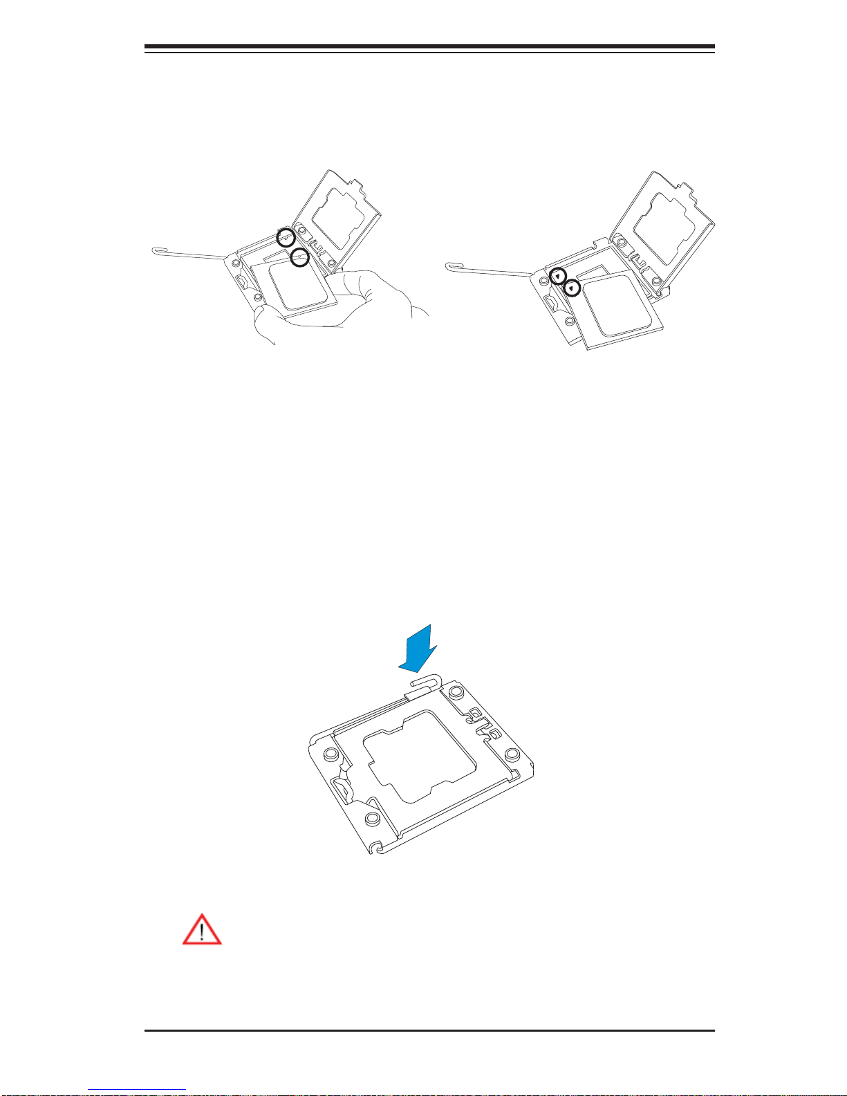
Align the CPU key, which is a semi-circle cutout, against the socket key, 5.
which is the notch below the gold color dot on the side of the socket.
Align Pin 1 on the CPU against Pin 1 on the CPU socket.6.
CPU Key
CPU Pin 1
Once both CPU and the socket are aligned, carefully lower the CPU straight 7.
down into the socket. (To avoid damaging the CPU or the socket, do not rub
the CPU against the surface of the socket or its pins.)
With the CPU inside the socket, inspect the four corners of the CPU to make 8.
sure that the CPU is properly installed.
Once the CPU is securely seated on the socket, lower the CPU load plate to 9.
the socket.
Use your thumb to gently push the socket clip down to the clip lock.10.
Warning: Please save the plastic cap. The motherboard must be shipped
with the plastic cap properly installed to protect the CPU socket pins.
Shipment without the plastic cap properly installed will cause damage
to the socket pins.
3-3
X8QB6-F/X8QBE-F Motherboard User's Manual
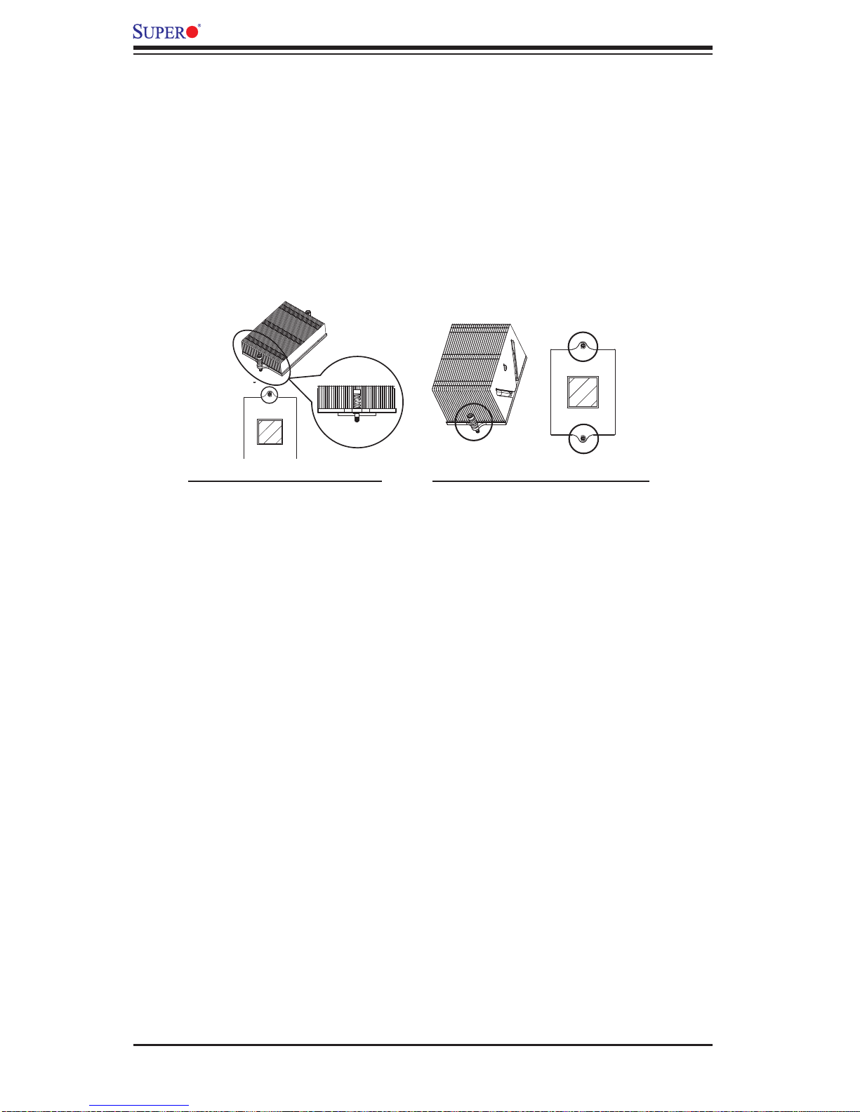
Installing a Passive CPU Heatsink
Apply the proper amount of thermal grease (with thickness of up to 0.13 mm) 1.
to the heatsink.
Place the heatsink on top of the CPU so that the two mounting holes on the 2.
heatsink are aligned with those on the retention mechanism.
3. Inser t t wo push -pin s on the s ides of t he heats ink thr ough th e mounti ng hol es
on the mot her board a nd tur n the pus h- pins c lock wi se to loc k them .
1U Heatsink (SNK-P0044P) 2U/4U Heatsink (SNK-P0045P)
3-4
 Loading...