

Supero X8DTT, X8DTT-F, X8DTT-IBX, X8DTT-IBXF, X8DTT-IBQ User Manual
...
X8DTT
X8DTT-F
X8DTT-IBX
X8DTT-IBXF
X8DTT-IBQ
X8DTT-IBQF
USER’S MANUAL
Revision 1.0b

The information in this User’s Manual has been carefully reviewed and is believed to be accurate.
The vendor assumes no responsibility for any inaccuracies that may be contained in this document,
makes no commitment to update or to keep current the information in this manual, or to notify any
person or organization of the updates. Please Note: For the most up-to-date version of this
manual, please see our web site at www.supermicro.com.
Super Micro Computer, Inc. ("Supermicro") reserves the right to make changes to the product
described in this manual at any time and without notice. This product, including software and documentation, is the property of Supermicro and/or its licensors, and is supplied only under a license.
Any use or reproduction of this product is not allowed, except as expressly permitted by the terms
of said license.
IN NO EVENT WILL SUPERMICRO BE LIABLE FOR DIRECT, INDIRECT, SPECIAL, INCIDENTAL,
SPECULATIVE OR CONSEQUENTIAL DAMAGES ARISING FROM THE USE OR INABILITY TO
USE THIS PRODUCT OR DOCUMENTATION, EVEN IF ADVISED OF THE POSSIBILITY OF
SUCH DAMAGES. IN PARTICULAR, SUPERMICRO SHALL NOT HAVE LIABILITY FOR ANY
HARDWARE, SOFTW ARE, OR DA TA STORED OR USED WITH THE PRODUCT, INCLUDING THE
COSTS OF REPAIRING, REPLACING, INTEGRATING, INSTALLING OR RECOVERING SUCH
HARDWARE, SOFTWARE, OR DATA.
Any disputes arising between manufacturer and customer shall be governed by the laws of Santa
Clara County in the State of California, USA. The State of California, County of Santa Clara shall
be the exclusive venue for the resolution of any such disputes. Super Micro's total liability for all
claims will not exceed the price paid for the hardware product.
FCC Statement: This equipment has been tested and found to comply with the limits for a Class
A digital device pursuant to Part 15 of the FCC Rules. These limits are designed to provide
reasonable protection against harmful interference when the equipment is operated in a commercial
environment. This equipment generates, uses, and can radiate radio frequency energy and, if not
installed and used in accordance with the manufacturer’s instruction manual, may cause harmful
interference with radio communications. Operation of this equipment in a residential area is likely
to cause harmful interference, in which case you will be required to correct the interference at your
own expense.
California Best Management Practices Regulations for Perchlorate Materials: This Perchlorate
warning applies only to products containing CR (Manganese Dioxide) Lithium coin cells. “Perchlorate
Material-special handling may apply. See www.dtsc.ca.gov/hazardouswaste/perchlorate”
WARNING: Handling of lead solder materials used in this
product may expose you to lead, a chemical known to
the State of California to cause birth defects and other
reproductive harm.
Manual Revision 1.0b
Release Date: June 18, 2013
Unless you request and receive written permission from Super Micro Computer, Inc., you may not
copy any part of this document.
Information in this document is subject to change without notice. Other products and companies
referred to herein are trademarks or registered trademarks of their respective companies or mark
holders.
Copyright © 2013 by Super Micro Computer, Inc.
All rights reserved.
Printed in the United States of America

Preface
About This Manual
This manual is written for system integrators, PC technicians and knowledgeable
PC users. It provides information for the installation and use of the X8DTT/
X8DTT-F/X8DTT-IBX/X8DTT-IBXF/X8DTT-IBQ/X8DTT-IBQF motherboard.
About This Motherboard
The X8DTT Series motherboards support the Intel 5500/5600 Series
Processor platform and the QuickPath Interconnect (QPI) Technology , providing the
next generation point-to-point system interface, replacing the current Front Side Bus.
With the 5500/5600 Series Processor built-in, the X8DTT/-F/-IBX/-IBXF/-IBQ/-IBQF
offers substantial enhancement in system performance with increased bandwidth
and unprecedented scalability optimized for HPC/Cluster, high-end servers and
intensive applications. Please refer to our web site (http://www.supermicro.com/
products/) for updates on supported processors. This product is intended to be
installed and serviced by professional technicians.
Preface
Manual Organization
Chapter 1 describes the features, specifi cations and performance of the mother-
board and provides detailed information about the chipset.
Chapter 2 provides hardware installation instructions. Read this chapter when in-
stalling the processor, memory modules and other hardware components into the
system. If you encounter any problems, see Chapter 3, which describes troubleshooting procedures for video, memory and system setup stored in the CMOS.
Chapter 4 includes an introduction to BIOS and provides detailed information on
running the CMOS Setup utility.
Appendix A lists BIOS POST Error Codes. Appendix B provides Software Installation Instructions.
iii

X8DTT/-F/-IBX/-IBXF/-IBQ/-IBQF User's Manual
Conventions Used in the Manual
Special attention should be given to the following symbols for proper installation
and to prevent product damage or bodily injury:
Warning: Important information given to ensure proper system installation or to prevent
damage to the components.
Note: Additional Information given to differentiate various models or to
ensure correct system setup.
iv

Contacting Supermicro
Headquarters
Address: Super Micro Computer, Inc.
980 Rock Ave.
San Jose, CA 95131 U.S.A.
Tel: +1 (408) 503-8000
Fax: +1 (408) 503-8008
Email: marketing@supermicro.com (General Information)
support@supermicro.com (Technical Support)
Contacting Supermicro
Web Site:
Europe
Address: Super Micro Computer B.V.
Tel: +31 (0) 73-6400390
Fax: +31 (0) 73-6416525
Email: sales@supermicro.nl (General Information)
Asia-Pacifi c
Address: Super Micro Computer, Inc.
www.supermicro.com
Het Sterrenbeeld 28, 5215 ML
's-Hertogenbosch, The Netherlands
support@supermicro.nl (Technical Support)
rma@supermicro.nl (Customer Support)
3F, No. 150, Jian 1st Rd.
Zhonghe Dist., New Taipei City 23511
Taiwan (R.O.C)
Tel: +886-(2) 8226-3990
Fax: +886-(2) 8226-3992
Web Site:
Technical Support:
Email: support@supermicro.com.tw
Tel: +886-(2)-8226-3990
www.supermicro.com.tw
v

X8DTT/-F/-IBX/-IBXF/-IBQ/-IBQF User's Manual
Table of Contents
Table of Contents
Preface
Chapter 1 Introduction
1-1 Overview ........................................................................................................1-1
1-2 Chipset Overview ............................................................................................1-9
1-3 Special Features ...........................................................................................1-10
1-4 PC Health Monitoring .................................................................................... 1-10
1-5 ACPI Features ................................................................................................1-11
1-6 Power Supply ................................................................................................1-12
1-7 Overview of the Nuvoton WPCM450 Controller ........................................... 1-12
Chapter 2 Installation
2-1 Standardized Warning Statements ................................................................. 2-1
2-2 Static-Sensitive Devices ..................................................................................2-4
2-3 Motherboard Installation ..................................................................................2-5
Tools Needed .................................................................................................. 2-5
Installation Instructions ....................................................................................2-5
2-4 Processor and Heatsink Installation................................................................2-6
Installing a CPU Heatsink ............................................................................... 2-8
2-5 Memory Installation ...................................................................................... 2-10
2-6 Control Panel Connectors/IO Ports...............................................................2-15
Back Panel Connectors/IO Ports .................................................................. 2-15
Back Panel Connector Pin Defi nitions .......................................................... 2-16
Universal Serial Bus (USB) ...................................................................... 2-16
Ethernet Ports .......................................................................................... 2-17
Serial Ports ............................................................................................... 2-18
Video Connector .......................................................................................2-18
Infi niBand Connection (X8DTT-IBX/IBXF/IBQ/IBQ/IBQF) ........................2-19
Unit Identifi er Switches .............................................................................2-20
Front Control Panel ....................................................................................... 2-21
Front Control Panel Pin Defi nitions............................................................... 2-22
Power LED ..............................................................................................2-22
HDD/FP UID Switch ................................................................................. 2-22
NIC1 LED Indicator .................................................................................. 2-23
NIC2 LED Indicator .................................................................................. 2-23
Overheat (OH)/Fan Fail/PWR Fail/UID LED ............................................2-24
Power Fail LED ........................................................................................ 2-24
Reset Button ........................................................................................... 2-25
vi

Table of Contents
Power Button ...........................................................................................2-25
2-7 Connecting Cables ........................................................................................ 2-26
20-pin Proprietary Power Connectors ...................................................... 2-26
4-pin Auxiliary Power Connector .............................................................2-27
Fan Headers ............................................................................................. 2-28
NMI Header ..............................................................................................2-29
Internal Buzzer ......................................................................................... 2-29
Wake-On-LAN ..........................................................................................2-30
T-SGPIO Headers .................................................................................... 2-30
SMB (I
IPMB I
2
C) Connector ................................................................................ 2-31
2
C SMB (For X8DTT-F/IBXF/IBQF only) ....................................... 2-31
2-8 Jumper Settings ............................................................................................ 2-32
Explanation of Jumpers ................................................................................ 2-32
GLAN Enable/Disable .............................................................................. 2-32
CMOS Clear .............................................................................................2-33
Watch Dog Enable/Disable ...................................................................... 2-33
Power Setting Select ................................................................................ 2-34
VGA Enable .............................................................................................. 2-34
J_UID_OW (-Overwriting) ........................................................................2-35
BMC Enable (For X8DTT-F/IBXF/IBQF only) .......................................... 2-36
2-9 Onboard Indicators ........................................................................................ 2-37
GLAN LEDs .............................................................................................. 2-37
BMC Heartbeat LED (X8DTT-F/IBX-F/IBQF) ........................................... 2-37
Infi niBand LED Indicators (LEB1/LEB2) (X8DTT-IBX/IBXF/IBQ/IBQF) ...2-38
Onboard Power LED
.....................................................................2-38
2-10 Serial ATA and PCI-E Connections ............................................................... 2-39
Serial ATA Ports........................................................................................ 2-39
PCI-Express x16 Gen. 2 Slot ................................................................... 2-39
Chapter 3 Troubleshooting
3-1 Troubleshooting Procedures ........................................................................... 3-1
3-2 Technical Support Procedures ........................................................................ 3-3
3-3 Frequently Asked Questions ........................................................................... 3-3
3-4 Returning Merchandise for Service.................................................................3-4
Chapter 4 BIOS
4-1 Introduction ...................................................................................................... 4-1
4-2 Main Setup ......................................................................................................4-2
4-3 Advanced Setup Confi gurations...................................................................... 4-4
4-4 Security Settings ........................................................................................... 4-25
vii

X8DTT/-F/-IBX/-IBXF/-IBQ/-IBQF User's Manual
4-5 Boot Confi guration ........................................................................................4-26
4-6 Exit Options ................................................................................................... 4-27
Appendix A BIOS Error Beep Codes
A-1 BIOS Error Beep Codes ................................................................................. A-1
Appendix B Software Installation Instructions
B-1 Installing Software Programs .......................................................................... B-1
B-2 Confi guring Super Doctor® III ......................................................................... B-2
viii

Chapter 1: Introduction
Chapter 1
Introduction
1-1 Overview
Checklist
Congratulations on purchasing your computer motherboard from an acknowledged
leader in the industry. Supermicro boards are designed with the utmost attention to
detail to provide you with the highest standards in quality and performance. Check
that the following items have all been included with your motherboard. If anything
listed here is damaged or missing, contact your retailer.
The following items are included in the bulk package.
• One (1) Supermicro Mainboard
• Two (2) Serial ATA cables (CBL-0044Lx2)
Note: For your system to work properly, please follow the links below to
download all necessary drivers/utilities and the user's manual for your
motherboard.
SMCI product mauals: http://www.supermicro.com/support/manuals/
Product Drivers and utilities: ftp://ftp.supermicro.com/
If you have any questions, please contact our support team at support@supermicro.
com.
1-1
X8DTT/-F/-IBX/-IBXF/-IBQ/-IBQF User's Manual
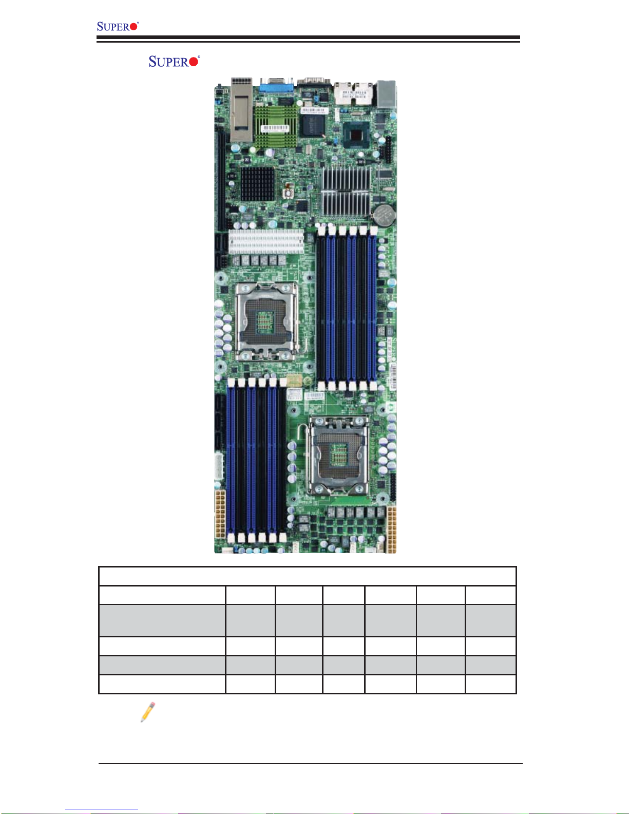
X8DTT/-F/-IBX/-IBXF/-IBQ/-IBQF Motherboard Image
Model Variations (Differences between X8DTT models)
IPMI 2.0 w/ KVM Over
LAN
Infi niBand Connect. No No Yes Yes Yes Yes
DDR IB No No Yes Yes No No
QDR IB No No No No Yes Yes
Note: The drawings and pictures shown in this manual were based on the
latest PCB Revision available at the time of publishing of the manual. The
motherboard you’ve received may or may not look exactly the same as
the graphics shown in the manual.
X8DTT /-F /-IBX /-IBXF /-IBQ /IBQF
No Yes No Yes No Yes
1-2
Chapter 1: Introduction
X8DTT/-F/-IBX/-IBXF/-IBQ/-IBQF Motherboard Layout
LE4
SW1
JNMI1
JWD1
JSPK1
J_UID_OW
J119
PCI-E 2.0 GEN2 X16
I-SATA0
I-SATA2
J19
I-SATA1
Intel
ICH-10R
(South Bridge)
CPU2
InfiniBand CTRL
VGA
X8DTT Series
Rev. 2.0
LEB2
LEB1
InfiniBand
Connector
T-SGPIO0
T-SGPIO1
COM1
LE2
JBMC1JPB
LAN2
IPMB
P2 DIMM1B
JPL1
(North Bridge)
P2 DIMM1A
Intel
5520/5500
P2 DIMM2B
JPG1
Nuvoton
WPCM450
JWOL1
JBT1
BIOS
LAN CTRL
P2 DIMM2A
LAN1
P2DIMM3B
P2DIMM3A
USB0/1
IPMI_LAN
PHY
JTPM1
USB2/3
JBAT1
Battery
I-SATA3
I-SATA4
I-SATA5
JP10
4-pin PWR
P1 DIMM3A
P1 DIMM2A
P1 DIMM2B
P1 DIMM1A
P1 DIMM1B
FAN3
P1 DIMM3B
JWR2
FAN4
JPEN1
CPU1
JF1
LE1
JWR1
FAN1
PWR I2C
FAN2
J18
Notes:
1. Jumpers not indicated are for test purposes only. For more information on
jumpers or components, refer to Chapter 2.
2. " " indicates the location of Pin 1.
3. When LEa LED is on, the onboard power connection is on. Make sure to
unplug the power cables before removing or installing components.
4. To use Hot-swap support on the 827 chassis, connect a cable to pins 2~3 on
JPEN1. Close pins 1~2 of JPEN1 with a cap to use regular PWR setting.
Warning: To avoid possible system overheating, please be sure to provide adequate
airfl ow to your system.
1-3
X8DTT/-F/-IBX/-IBXF/-IBQ/-IBQF User's Manual
X8DTT/-F/-IBX/-IBXF/-IBQ/-IBQF Quick Reference
LE4
LEB1
SW1
JNMI1
JWD1
JSPK1
J_UID_OW
J119
PCI-E 2.0 GEN2 X16
I-SATA0
I-SATA2
J19
I-SATA1
VGA
LEB2
InfiniBand
Connector
InfiniBand CTRL
JWOL1
Intel
ICH-10R
(South Bridge)
T-SGP IO0
BIOS
COM1
LE2
JBMC1JPB
Nuvoton
WPCM450
JBT1
IPMB
JPL1
5520/5500
(North Bridge)
LAN2
JPG1
LAN CTRL
Intel
USB0/1
LAN1
IPMI_LAN
PHY
JTPM1
USB2/3
JBAT1
Battery
X8DTT Series
T-SGP IO1
Rev. 2.0
P2 DIMM1A
CPU2
I-SATA3
I-SATA4
I-SATA5
JP10
4-pin PWR
P1 DIMM3A
JWR2
P1 DIMM3B
P1 DIMM2A
P1 DIMM2B
P1 DIMM1A
P1 DIMM1B
P2 DIMM1B
CPU1
P2 DIMM2B
P2DIMM3B
JF1
LE1
JWR1
P2DIMM3A
P2 DIMM2A
FAN4
JPEN1
FAN3
FAN2
J18
FAN1
PWR I2C
1-4

Chapter 1: Introduction
Quick Reference (See Chapter 2 for Details)
Jumper Description Default Setting
JBMC1 BMC Enable (X8DTT-F/-IBXF/-IBQF) Pins 1-2 (Enabled)
JBT1 CMOS Clear (See Section 2-8)
JPEN1 Normal Power Enable (Note 1-4 on P. 1-3) Pins 1-2 (Enabled)
JPG1 VGA Enable Pins 1-2 (Enabled)
JPL1 LAN1/2 Enable Pins 1-2 (Enabled)
J_UID_OW Red LED OW (Pins 7/8 of JF1) (Page 2-31) Off (Overwrites)
JWD1 Watch Dog Pins 1-2 (Reset)
Connector Description
COM1 COM1 Serial Port
FAN 1-4 System/CPU Fan Headers
Infi niBand Infi niBand Connector (X8DTT-/IBX/IBXF/IBQ/IBQF)
IPMB IPMB Header (for an IPMI Card) (X8DTT-F/-IBXF/-IBQF)
J119 Infi niBand I
2
C Debug Header (-/IBX/IBXF/IBQ/IBQF)
JF1 Front Panel Connector
JNMI1 NMI (Non-Maskable Interrupt) Header
JP10 Onboard 4-pin Power Connector
JPSK1 Internal Speaker/Buzzer Header
JTPM1 Trusted Platform Module Header
JWR1/JWR2 12V 20-pin Power Connector (See P. 2-21)
JWOL1 Wake-On-LAN Header
LAN1/2 Gigabit Ethernet (RJ45) Ports
(IPMI dedicated) LAN LAN (RJ45) Port for IPMI 2.0 (X8DTT-F/-IBXF/-IBQF)
SATA0 ~ SATA5 (Intel South Bridge) SATA Ports
SMBus System Management Bus (SMBus) I
2
C Header (J18)
SW1 Unit Identifi er Switch
T-SGPIO-0/T-SGPIO-1 Serial General Purpose Input/Output Headers
USB0/1, USB 2/3 Universal Serial Bus (USB) Ports 0/1, 2/3
VGA Video Port
LED Description
LE1 On board S tandby P WR warn ing LED In dicato r
LE2 BMC Heartbeat LED (Green/Blinking: Normal) (X8DTT-F/-IBXF/-IBQF)
LE4 (Rear) Unit Identifi er (UID) LED Indicator
LEB1 Infi niBand Link LED (X8DTT-IBX/-IBXF/-IBQ/-IBQF)
LEB2 Infi niBand Activity LED (X8DTT-IBX/-IBXF/-IBQ/-IBQF)
1-5

X8DTT/-F/-IBX/-IBXF/-IBQ/-IBQF User's Manual
Motherboard Features
CPU
• Two Intel
two full-width Intel QuickPath Interconnect (QPI) links with a total of up to 51.2
GT/s Data Transfer Rate (6.4 GT/s per direction)
Memory
®
5500/5600 Series (LGA 1366) processors, each processor supporting
• 12 240-pin DIMM sockets support up to 192 GB of Registered ECC or up to
48 GB of Unbuffered ECC/Non-ECC DDR3 1333/1066/800 MHz Memory (See
Section 2-4 in Chapter 2 for DIMM Slot Population.)
Chipset
• Intel 5520 chipset, including: the 5520 (North Bridge) and the ICH10R (South
Bridge).
Note: Intel 5500 Chipset is available for OEM only.
Expansion Slot
• One PCI-E x16 Gen. 2.0 slot
BIOS
• 32 Mb AMI SPI Flash ROM
• ACPI 1.0/2.0/3.0, Plug and Play (PnP), and USB Keyboard support
PC Health Monitoring
• Onboard voltage monitors for CPU1 VCore, CPU2 VCore, +5Vin, 12Vcc (V),
VP1 DIMM, VP2 DIMM, +3.3Vcc (V), and Battery Voltage
• Fan status monitor with fi rmware control
• CPU/chas sis tempe rature mo nitors
• Plat form Envir onment C ontro l Inter face ( PECI) ready
• CPU fan a uto -of f in sl eep mo de
• CPU slo w-d own on tem peratur e overheat
• Pulse W idth M odulat ion (PW M) Fan Cont rol
• CPU th ermal t rip su ppor t for p roce ssor p rotect ion, powe r LED
• Power-up mo de co ntrol fo r rec overy f rom AC powe r loss
• Auto -sw itchin g voltag e regul ator for C PU cor es
• System ove rheat / Fan Fail LED Indic ator an d cont rol
• System r esour ce ale rt v ia Supe ro Doc tor II I
ACPI Features
• Slow blinking LED for suspend state indicator
• Main switch override mechanism
1-6

Chapter 1: Introduction
• ACPI Po wer M ana gem ent
• Keyboard Wakeup from Soft-off
Onboard I/O
• Intel ICH10R supports six SATA ports (RAID0, RAID1, RAID10, RAID5 supported
in the Windows OS Environment and RAID 0, RAID 1, RAID 10 supported for
the Linux OS)
• Nuvoton W P CM 45 0 B M C (Ba seb oa rd M ana gem ent C ont ro lle r) supp orts IP MI
2.0 with K V M supp or t (X8DTT-F/-IBXF/-IBQF)
• Intel 82576 D ual - L A N Gi gabi t Ether net C ont roll er sup ports du al Gi ga -b it L A N
ports
• Onbo ard PHY Ch ip suppo rt s IPMI de dicate d LA N (X8 DTT-F/-IBX F/-IBQ F)
• One C OM por t
• Infi niBand Connector
• Up to fou r USB 2.0 (Univer sal Seria l Bus) conne ctions (2 Por ts and 2 Front
Headers)
• Super I /O: Winb ond W8 3527HG
Other
• Wake-on-LAN (WOL)
• Console redirection
• Onbo ard Fan Spe ed Cont rol by The rmal M anage ment via B IOS
CD/Diskette Utilities
• BIOS fl ash upgrade utility and device drivers
Dimensions
• Propr ieta ry 16.6 4" (L) x 6.5 0" ( W) (422.6 6 mm x 165.10 mm)
1-7

X8DTT/-F/-IBX/-IBXF/-IBQ/-IBQF User's Manual
QSFP
#1
#1
#1
DDR3 DIMM
#2
#2
#2
AA
BB
CC
DDR3 DIMM
MT25408
Connect-X IB
PCI-E Gen2/DDR or QDR
(Depupulate
for 5500)
DDR II
PROCESSOR#0
Port1 Port0
Ports
3,4
Ports
5,6
Ports
7,8,9,10
PCI-E x16 Slot
PE
5
4-1
PE
WBD
BMC/VGA
Intel 5520/5500
PCI
PROCESSOR#1
Ports
2,1
CLINK
ESI
CLINK
DMI
ICH10R
LPC
F
Kawela
RJ45 RJ45
SST25
VF016
SPI
SATA
SATA #1
SATA #2
SATA #3
SATA #4
SATA #5
SATA #6
LPCIO W83527
ACPI
KBC
#2
#2
#2
DDR3 DIMM
#1
#1
#1
DD
EE
F
DDR3 DIMM
VGA CONN
RTL8201N PHY
Dedicate LAN
Block Diagram of the 5500/5600 Series Processor Platform
Note 1: This is a general block diagram. Please see the previous Mother-
board Features pages for details on the features of each motherboard.
Note 2: Intel 5500 Chipset is available for OEM only.
1-8

Chapter 1: Introduction
1-2 Chipset Overview
Built up on th e fun cti ona lit y an d the c ap abil it y of th e 55 0 0/5 6 0 0 Ser ie s Pro ce sso r
platf orm, t he X8DT T/-F/-IBX /- IBXF/- IBQ /- IBQF m other board p rovide s the per fo rmance a nd feature set req uired for dual -proc essor-bas ed systems wit h confi gu-
ration o ption s optimi zed for inte nsive app licat ions, H igh Per fo rman ce Co mputi ng
(HPC)/Cluster and server platforms. The 550 0/5600 Series Processor platform
consists of the 550 0/ 5 600 Series (LGA 1366) processor, the 5520 (North Bridge),
and the IC H10R (South Br id ge). With th e Intel Q uic kPat h inter co nne ct (QPI) c on troller built-in, the 5500/5600 Series Processor platform is the fi rst dual-proce ssi n g
platform to offer the next generation point-to-point system interconnect interface
that replaces the current Front Side Bus Technology, substantially enhancing
system performance by utilizing serial link interconnections, allowing for increased
bandwidth and scalability.
The IOH connects to each processor through an independent QPI (QuickPath
interconnect) link. Each link consists of 20 pairs of unidirectional differential lanes
for tra nsmis sio n and re cei ving i n addit ion t o a dif fer entia l for wa rded c lo ck. A f ull width Q PI link pair p rovide s 84 si gnals. Ea ch proc ess or suppo rt s two Q uickPat h
links, one g oing to th e other pr oce ssor an d the othe r to the 5 520.
The 552 0 suppor ts up to 36/ 24 PCI Expre ss Gen2 lan es peer-to -peer rea d and
write transactions. The ICH10R provides multiple PCI-Express SATA and USB
connections.
In additi on, th e 55 00 /5 60 0 Se rie s Proc es sor pl atf or m also of fe rs a w ide ra nge of
RA S (Reliabilit y, Availabili ty and Ser vice ability) featur es. These feat ures inclu de
memor y i nter fa ce ECC, x4 /x8 S ing le Devi ce D ata C or rec tio n (SDD C), Cyclic Re dundancy Check (CRC), parity protection, out-of-band register access via SMBus,
memory mirroring, memory sparing, and Hot-plug support on the PCI-Express
Interface.
Note: Intel 5500 Chipset is available for OEM only.
Main Features of the 5500/5600 Series Processor and the
5520 Chipset
• Four processor cores in each processor with 8MB shared cache among cores
• Two full-width Intel QuickPath interconnect links, up to 6.4 GT/s of data transfer
rate in each direction
• Virtualization Technology, Integrated Management Engine supported
• Point-to-point cache coherent interconnect, Fast/narrow unidirectional links, and
Concurrent bi-directional traffi c
1-9

X8DTT/-F/-IBX/-IBXF/-IBQ/-IBQF User's Manual
1-3 Special Features
Recovery from AC Power Loss
BIOS provides a setting for you to determine how the system will respond when AC
power is lost and then restored to the system. You can choose for the system to
remain powered off (in which case you must press the power switch to turn it back
on) or for it to automatically return to a power- on state. See the Advanced BIOS
Setup section to change this setting. The default setting is Last State.
1-4 PC Health Monitoring
This section describes the PC health monitoring features of the X8DTT/-F/-IBX/IBXF/-IBQ/-IBQF. All have an onboard System Hardware Monitor chip that supports PC health monitoring. An onboard voltage monitor will scan these onboard
voltages continuously: CPU1 VCore, CPU2 VCore, +5Vin, 12Vcc (V), VP1 DIMM,
VP2 DIMM, +3.3Vcc (V), and Battery Voltage. Once a voltage becomes unstable,
a warning is given or an error message is sent to the screen. Users can adjust the
voltage thresholds to defi ne the sensitivity of the voltage monitor.
Fan Status Monitor with Firmware Control
The PC health monitor can check the RPM status of the cooling fans. The onboard
CPU and chassis fans are controlled by Thermal Management via BIOS (under
Hardware Monitoring in the Advanced Setting).
Environmental Temperature Control
The thermal control sensor monitors the CPU temperature in real time and will turn
on the thermal control fan whenever the CPU temperature exceeds a user-defi ned
threshold. The overheat circuitry runs independently from the CPU. Once it detects
that the CPU temperature is too high, it will automatically turn on the thermal fan
control to prevent any overheat damage to the CPU. The onboard chassis thermal
circuitry can monitor the overall system temperature and alert users when the chassis temperature is too high.
Warning: To avoid possible system overheating, please be sure to provide
adequate airfl ow to your system.
System Resource Alert
This feat ure is available wh en used with Sup er Doctor ® III in the Win dows OS
environment or used with Super Doctor II in Linux. Super Doctor is used to
notif y the user of cer tain system events. For example, you can also confi gure
1-10

Chapter 1: Introduction
Super Do ctor to provi de you with warn ings when the sys tem temperatur e, CPU
temperat ures, volt ages a nd fan spe eds go beyon d a pre- defi ned range.
1-5 ACPI Features
ACPI stands for Advanced Confi guration and Power Interface. The ACPI specifi ca-
tion defi nes a fl exible and abstract hardware interface that provides a standard
way to integrate power management features throughout a PC system, including
its hardware, operating system and application software. This enables the system
to automatically turn on and off peripherals such as CD-ROMs, network cards, hard
disk drives and printers.
In addition to enabling operating system-directed power management, ACPI
provides a generic system event mechanism for Plug and Play and an operating
system-independent interface for confi guration control. ACPI leverages the Plug
and Play BIOS data structures while providing a processor architecture-independent
implementation that is compatible with Windows XP/Windows 2003/Windows 2008/
Windows Vista Operating Systems.
Slow Blinking LED for Suspend-State Indicator
When the CPU goes into a suspend state, the chassis power LED will start blinking
to indicate that the CPU is in suspend mode. When the user presses any key, the
CPU will wake-up and the LED will automatically stop blinking and remain on.
Main Switch Override Mechanism
When an ATX power supply is used, the power button can function as a system
suspend button to make the system enter a SoftOff state. The monitor will be
suspended and the hard drive will spin down. Pressing the power button again
will cause the whole system to wake-up. During the SoftOff state, the ATX power
supply provides power to keep the required circuitry in the system "alive." In case
the system malfunctions and you want to turn off the power, just press and hold
the power button for 4 seconds. This option can be set in the Power section of the
BIOS Setup routine.
Wake-On-LAN (WOL)
Wake-On-LAN is defi ned as the ability of a management application to remotely
power up a computer that is powered off. Remote PC setup, up-dates and asset
tracking can occur after hours and on weekends so that daily LAN traffi c is kept
to a minimum and users are not interrupted. The motherboard has a 3-pin header
(WOL) to connect to the 3-pin header on a Network Interface Card (NIC) that has
WOL capability. In addition, an onboard LAN controller can also support WOL
1-11

X8DTT/-F/-IBX/-IBXF/-IBQ/-IBQF User's Manual
without any connection to the WOL header. The 3-pin WOL header is to be used
with a LAN add-on card only.
Note: Wake-On-LAN requires an ATX 2.01 (or above) compliant power
supply.
1-6 Power Supply
As with all computer products, a stable power source is necessary for proper and
reliable operation. It is even more important for processors that have high CPU
clock rates.
It is strongly recommended that you use a high quality power supply that meets ATX
power supply Specifi cation 2.02 or above. It must also be SSI compliant (For more
information, please refer to the web site at http://www.ssiforum.org/). Additionally, in
areas where noisy power transmission is present, you may choose to install a line
fi lter to shield the computer from noise. It is recommended that you also install a
power surge protector to help avoid problems caused by power surges.
Note: The X8DTT/-F/-IBX/-IBXF/-IBQ/-IBQF supports proprietary power
connectors. Please refer to Page 2-21 for detailed information on power
supply for the motherboard.
1-7 Overview of the Nuvoton WPCM450 Controller
The Nuvoton WPCM450, a Baseboard Management Controller (BMC), supports
the 2D/VGA-compatible Graphics Core with the PCI interface, Virtual Media, and
Keyboard/Video/Mouse (KVM) Redirection modules.
The WPCM450 BMC interfaces with the host system via a PCI interface to communicate with the graphics core. It supports USB 2.0 and 1.1 for remote keyboard/
mouse/virtual media emulation. It also provides LPC interface to control Super IO
functions. The WPCM450 is connected to the network via an external Ethernet
PHY module.
The WPCM450 communicates with onboard components via six SMBus interfaces,
fan control, Platform Environment Control Interface (PECI) buses.
Note: For more information on IPMI confi guration, please refer to the
Embedded IPMI User's Guide posted on our website @ http://www.supermicro.com/support/manuals/.
1-12
Chapter 2: Installation
Chapter 2
Installation
2-1 Standardized Warning Statements
The following statements are industry-standard warnings, provided to warn the user
of situations which have the potential for bodily injury . Should you have questions or
experience diffi culty, contact Supermicro's Technical Support department for assis-
tance. Only certifi ed technicians should attempt to install or confi gure components.
Read this section in its entirety before installing or confi guring components in the
Supermicro chassis.
Battery Handling
Warning!
There is a danger of explosion if the battery is replaced incorrectly. Replace the
battery only with the same or equivalent type recommended by the manufacturer.
Dispose of used batteries according to the manufacturer's instructions
電池の取り扱い
電池交換が正しく行われなかった場合、破裂の危険性があります。交換する電池はメー
カーが推奨する型、または同 等のものを使 用下さい。使用済電池は製造元の指示に従
って処 分して 下さい 。
警告
电池更换不当会有爆炸危险。请只使用同类电池或制造商推荐的功能相当的电池更
换原有电池。请按制造商的说明处理废旧电池。
警告
電池更換不當會有爆炸危險。請使用製造商建議之相同或功能相當的電池更換原有
電池。請按照製造商的說明指示處理廢棄舊電池。
Warnung
Bei Einsetzen einer falschen Batterie besteht Explosionsgefahr. Ersetzen Sie die
Batterie nur durch den gleichen oder vom Hersteller empfohlenen Batterietyp.
Entsorgen Sie die benutzten Batterien nach den Anweisungen des Herstellers.
2-1

X8DTT/-F/-IBX/-IBXF/-IBQ/-IBQF User's Manual
!הרהזא
Attention
ﻲﺋﺎﻬﻨﻟﺍ ﺺﻠﺨﺘﻟﺍ ﻦﻣ ﺞﺘﻨﻤﻟﺍ ﺍﺬﻫ ﻪﻌﻣ ﻞﻣﺎﻌﺘﻟﺍ ﻲﻐﺒﻨﻳ ﻟ ﺎﻘﻓﻭ ﻊﻴﻤﺠﺔﻴﻨﻁﻮﻟﺍ ﺢﺋﺍﻮﻠﻟﺍﻭ ﻦﻴﻧﺍﻮﻘﻟﺍ ﺪﻨﻋ
Danger d'explosion si la pile n'est pas remplacée correctement. Ne la remplacer
que par une pile de type semblable ou équivalent, recommandée par le fabricant.
Jeter les piles usagées conformément aux instructions du fabricant.
¡Advertencia!
Existe peligro de explosión si la batería se reemplaza de manera incorrecta. Re-
emplazar la batería exclusivamente con el mismo tipo o el equivalente recomendado por el fabricante. Desechar las baterías gastadas según las instrucciones
del fabricante.
תנכס תמייקץוציפ .הניקת אל ךרדב הפלחוהו הדימב הללוסה לש ףילחהל שי
גוסב הללוסה תא מ םאותה תרבחלמומ ןרציתצ.
תוללוסה קוליס תושמושמה עצבל שי .ןרציה תוארוה יפל
ﺮﻄﺧ ﻙﺎﻨﻫ ﻦﻣ ﻝﺍﺪﺒﺘﺳﺍ ﺔﻟﺎﺣ ﻲﻓ ﺭﺎﺠﻔﻧﺍ ﺔﻳﺭﺎﻄﺒﻟﺍ ﺔﺤﻴﺤﺻ ﺮﻴﻏ ﺔﻘﻳﺮﻄﺑ ﻚﻴﻠﻌﻓ
ﺔﻳﺭﺎﻄﺒﻟﺍ ﻝﺍﺪﺒﺘﺳﺍ
ﻂﻘﻓ ﻉﻮﻨﻟﺍ ﺲﻔﻨﺑ ﺎﻬﻟﺩﺎﻌﻳ ﺎﻣ ﻭﺃ ﺎﻤﻛﺖﺻﻭﺃ ﺔﻌﻨﺼﻤﻟﺍ ﺔﻛﺮﺸﻟﺍ ﻪﺑ
ﺕﺎﻳﺭﺎﻄﺒﻟﺍ ﻦﻣ ﺺﻠﺨﺗ ﻟ ﺎﻘﻓﻭ ﺔﻠﻤﻌﺘﺴﻤﻟﺍﺔﻌﻧﺎﺼﻟﺍ ﺔﻛﺮﺸﻟﺍ ﺕﺎﻤﻴﻠﻌﺘ
경고!
배터리가 올바르게 교체되지 않으면 폭발의 위험이 있습니다. 기존 배터리와 동일
하거나 제조사에서 권장하는 동등한 종류의 배터리로만 교체해야 합니다. 제조사
의 안내에 따라 사용된 배터리를 처리하여 주십시오.
Waarschuwing
Er is ontploffi ngsgevaar indien de batterij verkeerd vervangen wordt. Vervang de
batterij slechts met hetzelfde of een equivalent type die door de fabrikant aanbevolen wordt. Gebruikte batterijen dienen overeenkomstig fabrieksvoorschriften
afgevoerd te worden.
2-2

Chapter 2: Installation
רצומה קוליס
Product Disposal
Warning!
Ultimate disposal of this product should be handled according to all national laws
and regulations.
製品の廃棄
この製品を廃棄処分する場合、国の関係する全ての法律・条例に従い処理する必要が
あります。
警告
本产品的废弃处理应根据所有国家的法律和规章进行。
警告
本產品的廢棄處理應根據所有國家的法律和規章進行。
Warnung
Die Entsorgung dieses Produkts sollte gemäß allen Bestimmungen und Gesetzen
des Landes erfolgen.
¡Advertencia!
Al deshacerse por completo de este producto debe seguir todas las leyes y regla-
mentos nacionales.
Attention
La mise au rebut ou le recyclage de ce produit sont généralement soumis à des
lois et/ou directives de respect de l'environnement. Renseignez-vous auprès de
l'organisme compétent.
!הרהזא
ו תויחנהל םאתהב תויהל בייח הז רצומ לש יפוס קוליס.הנידמה יקוח
ﻲﺋﺎﻬﻨﻟﺍ ﺺﻠﺨﺘﻟﺍ ﻦﻣ ﺞﺘﻨﻤﻟﺍ ﺍﺬﻫ ﻪﻌﻣ ﻞﻣﺎﻌﺘﻟﺍ ﻲﻐﺒﻨﻳ ﻟ ﺎﻘﻓﻭ ﻊﻴﻤﺠﺔﻴﻨﻁﻮﻟﺍ ﺢﺋﺍﻮﻠﻟﺍﻭ ﻦﻴﻧﺍﻮﻘﻟﺍ ﺪﻨﻋ
2-3

X8DTT/-F/-IBX/-IBXF/-IBQ/-IBQF User's Manual
경고!
이 제품은 해당 국가의 관련 법규 및 규정에 따라 폐기되어야 합니다.
Waarschuwing
De uiteindelijke verwijdering van dit product dient te geschieden in overeenstemming
met alle nationale wetten en reglementen.
2-2 Static-Sensitive Devices
Electrostatic Discharge (ESD) can damage electronic com ponents. T o prevent damage to your system board, it is important to handle it very carefully. The following
measures are generally suffi cient to protect your equipment from ESD.
Precautions
• Use a grounded wrist strap designed to prevent static discharge.
• Touch a grounded metal object before removing the board from the antistatic
bag.
• Handle the board by its edges only; do not touch its components, peripheral
chips, memory modules or gold contacts.
• When handling chips or modules, avoid touching their pins.
• Put the motherboard and peripherals back into their antistatic bags when not
in use.
• For grounding purposes, make sure your computer chassis provides excellent
conductivity between the power supply, the case, the mounting fasteners and
the motherboard.
• Use only the correct type of onboard CMOS battery as specifi ed by the
manufacturer. Do not install the onboard battery upside down to avoid possible
explosion.
Unpacking
The motherboar d is shipped i n a ntistati c pa ckaging to avoid static da mage. When
unpacking the board, make sure the person handling it is static protected.
2-4
Chapter 2: Installation
2-3 Motherboard Installation
All motherboards have standard mounting holes to fi t different types of chassis.
Make sure that the locations of all the mounting holes for both motherboard and
chassis match. Although a chassis may have both plastic and metal mounting
fasteners, metal ones are highly recommended because they ground the motherboard to the chassis. Make sure that the metal standoffs click in or are screwed in
tightly. Then use a screwdriver to secure the motherboard onto the motherboard
tray. Note: Some components are very close to the mounting holes. Please take
precautionary measures to prevent damage to these components when installing
the motherboard to the chassis.
Tools Needed
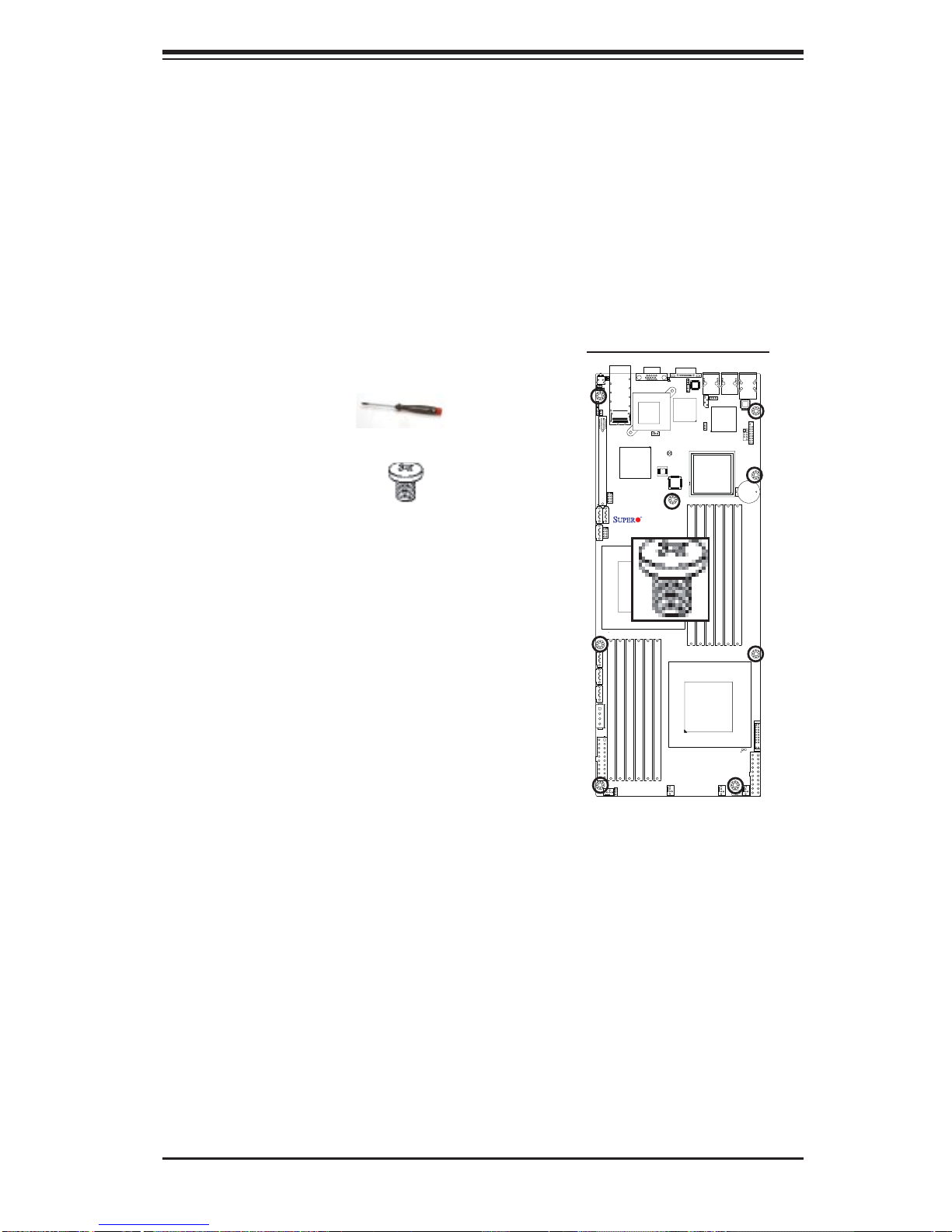
1. Phillips Screwdriver
2. Pan head #6 screws
Locations of Mounting Holes
X8DTT Series
Installation Instructions
Rev. 2.0
1. Install the IO shield into the chassis.
2. Locate the mounting holes on the motherboard. Refer to the layout above for mounting hole locations.
3. Locate the matching mounting holes on the
chassis. Align the mounting holes on the
motherboard against the mounting holes on
the chassis.
4. Install standoffs in the chassis as needed.
5. Install the motherboard into the chassis carefully to avoid damage to motherboard components.
Warning: To avoid damaging the motherboard and its components, please do not apply any force greater than 8 lb/sq.in (8 lbs. per square inch) when installing a screw
into a mounting hole.
6. Insert a Pan head #6 screw into a mounting hole on the motherboard and its
matching mounting hole on the chassis, using a Phillips screwdriver.
7. Repeat Step 4 to insert #6 screws to all mounting holes.
8. Make sure that the motherboard is securely placed on the chassis.
2-5
X8DTT/-F/-IBX/-IBXF/-IBQ/-IBQF User's Manual
2-4 Processor and Heatsink Installation
Warning: When handling the processor package, avoid placing direct pressure on the
label area of the fan.
Notes:
1. Always connect the power cord last and always remove it before adding, removing or changing any hardware components. Make sure that you install the
processor into the CPU socket before you install the CPU heatsink.
2. Make sure to install the motherboard into the chassis before you install the
CPU heatsink and heatsink fans.
3. When purchasing a 5500/5600 Series processor or when receiving a motherboard with a 5500/5600 Series processor pre-installed, make sure that the
CPU plastic cap is in place, and none of the CPU pins are bent; otherwise,
contact the retailer immediately.
4. Refer to the M B Features S ecti on for mo re deta ils on CPU s uppor t.
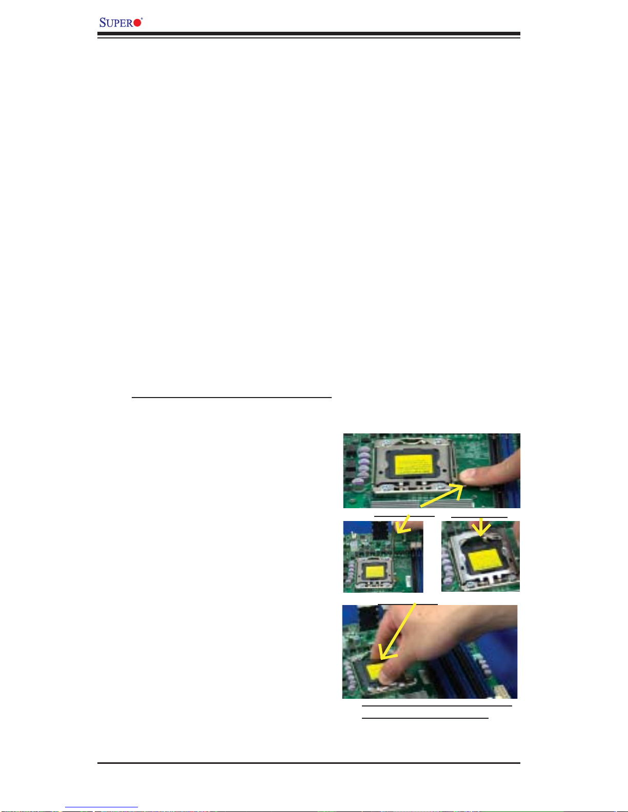
Installing an LGA 1366 Processor
1. Press the socket clip to release
the load plate, which covers the
CPU socket, from its locking
position.
Socket Clip
2. Gently lift the socket clip to
open the load plate.
Plastic Cap
3. Hold the plastic cap at its north
and south center edges to remove it from the CPU socket.
Load Plate
Hold the north & south edges of
the plastic cap to remove it
2-6

4. After removing the plastic cap, using
your thumb and the index fi nger,
hold the CPU at the north and south
center edges.
5. Align the CPU key, the semi-circle
cutout, against the socket key, the
notch below the gold color dot on
the side of the socket.
6. Once both the CPU and the socket
are aligned, carefully lower the CPU
straight down into the socket. (Do
not rub the CPU against the surface
of the socket or its pins to avoid
damaging the CPU or the socket.)
Chapter 2: Installation
Socket Keys CPU CPU SocketLoad Plate
7. With the CPU inside the socket, inspect the four corners of the CPU to
make sure that the CPU is properly
installed.
8. Once the CPU is securely seated
on the socket, lower the CPU load
plate to the socket.
9. Use your thumb to gently push the
socket clip down to the clip lock.
Warning: Please s ave th e p las ti c c a p. Th e
motherboard must be sh ipped with the pl astic cap properly installed to protect the CPU
socket pins. Shipment without the plastic
cap properly installed will cause damage
to the socket pins.
CPU Keys
2-7
X8DTT/-F/-IBX/-IBXF/-IBQ/-IBQF User's Manual
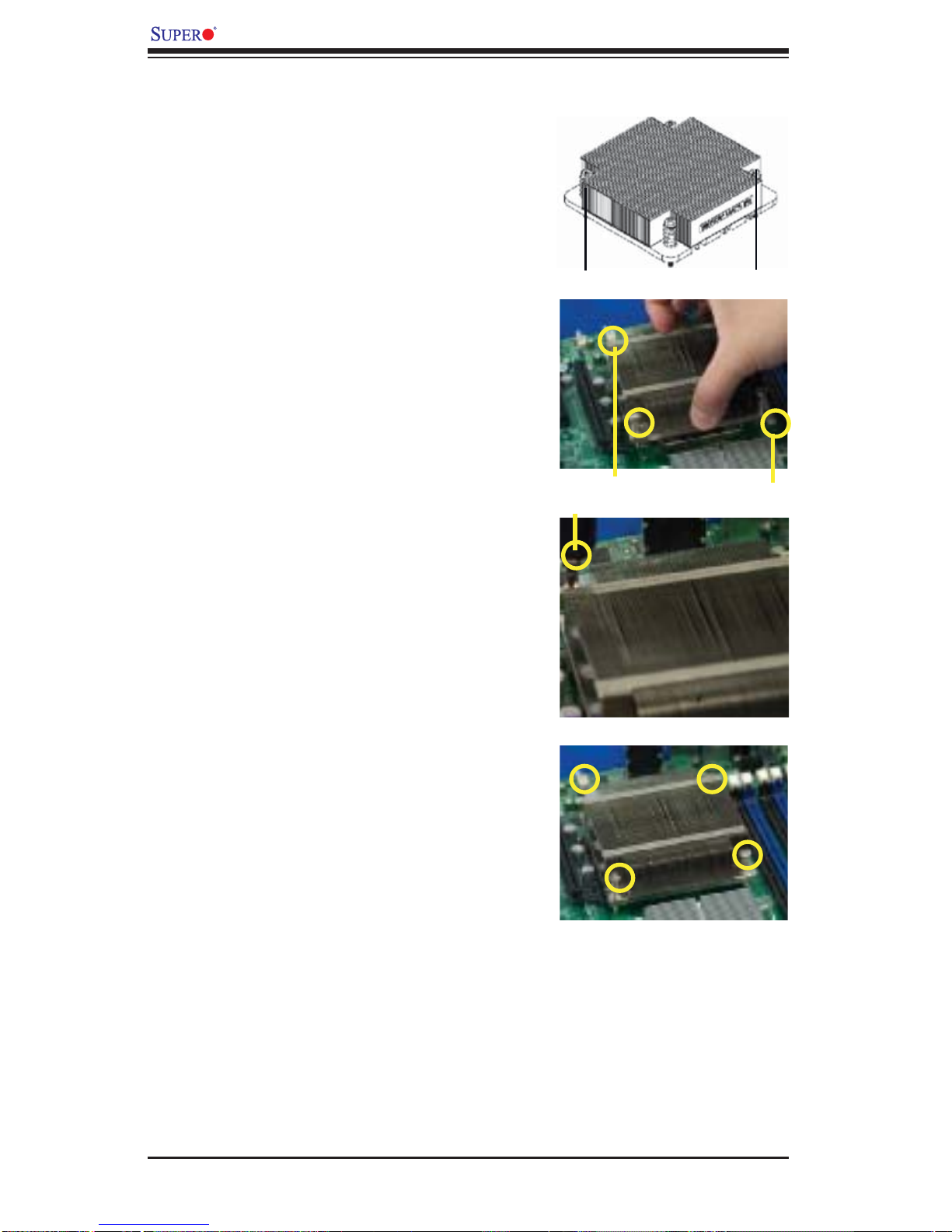
Installing a CPU Heatsink
1. Do not apply any thermal
grease to the heatsink or the
CPU die because the required
amount has already been applied.
2. Place the heatsink on top of the
CPU so that the four mounting
holes are aligned with those on
the retention mechanism.
3. Install two diagonal screws (ie
the #1 and the #2 screws) and
tighten them until just snug (-do
not fully tighten the screws to
avoid possible damage to the
CPU.)
Screw#1
Screw#1
Install Screw#1
Screw#2
Screw#2
4. Finish the installation by fully
tightening all four screws.
2-8
Chapter 2: Installation
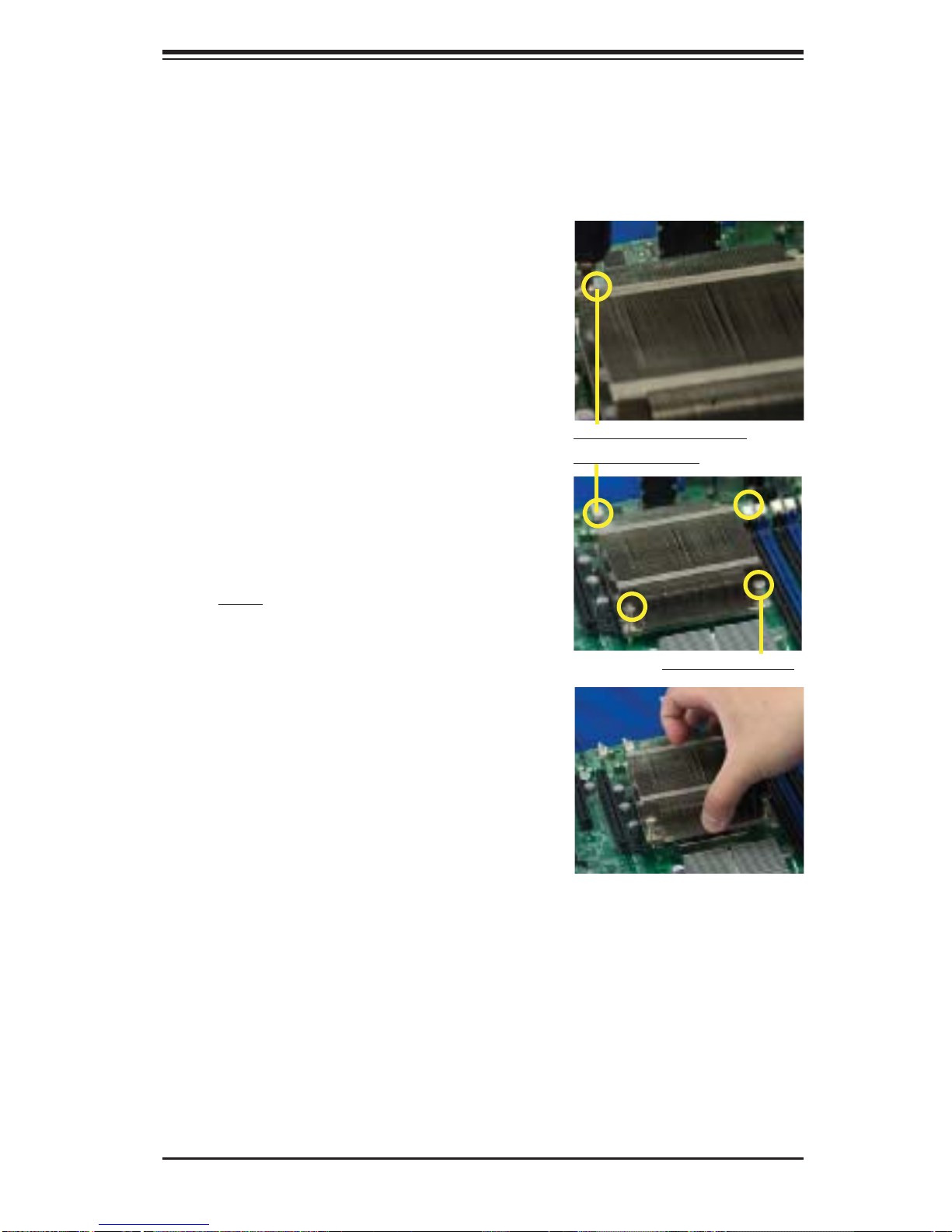
Removing the Heatsink
Warning: We do not recommend that the CPU or the heatsink be removed. However,
if you do need to remove the heatsink, please follow the instructions below to uninstall
the heatsink and prevent damage to the CPU or other components.
1. Unplug the power cord from the
power supply.
2. Disconnect the heatsink fan
wires from the CPU fan header.
3. Using a screwdriver, loosen and
remove the heatsink screws
from the motherboard in the sequence as show in the picture
on the right.
Using a screwdriver to
remove Screw#1
4. Hold the heatsink as shown
in the picture on the right and
gently wriggle the heatsink to
loosen it from the CPU. (Do not
use excessive force when wriggling the heatsink.)
5. Once the heatsink is loosened,
remove it from the CPU socket.
6. To reinstall the CPU and the
heatsink, clean the surface of
the CPU and the heatsink to get
rid of the old thermal grease.
Reapply the proper amount of
thermal grease on the surface
before reinstalling them on the
motherboard.
Remove Screw#2
2-9
X8DTT/-F/-IBX/-IBXF/-IBQ/-IBQF User's Manual
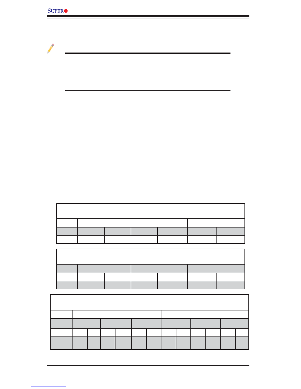
2-5 Memory Installation
Note: Check the S uper micro we b site for r ecom mende d memor y mo dules .
CAUTION
Exercise extreme care when installing or removing DIMM
module s to prevent any po ssib le damag e. Also n ote that th e
memor y is i nterl eaved to imp rove per fo rman ce (See ste p 1).
DIMM Installation
1. Insert the desired number of DIMMs into the memory slots, starting with
P1-DIMM 1A. For best memory performance, please install memory modules
of the same type and same speed on the memory slots as indicated on the
tables below. (See the Memory Installation Table Below.)
2. Insert each DIMM module vertically into its slot. Pay attention to the notch
along the bottom of the module to prevent inserting the DIMM module incorrectly.
3. Gently press down on the DIMM module until it snaps into place in the slot.
Repeat for all modules.
Memory Population for Optimal Performance
-For a motherboard with One CPU (CPU1) installed
Branch 0 Branch 1 Branch 2
3 DIMMs P1 DIMM1A P1 DIMM2A P1 DIMM3A
6 DIMMs P1 DIMM1A P1 DIMM1B P1 DIMM2A P1 DIMM2B P1 DIMM3A P1 DIMM3B
Memory Population for Optimal Performance
-For a motherboard with One CPU (CPU2) installed
Branch 0 Branch 1 Branch 2
3 DIMMs P2 DIMM1A P2 DIMM2A P2 DIMM3A
6 DIMMs P2 DIMM1A P2 DIMM1B P2 DIMM2A P2 DIMM2B P2 DIMM3A P2 DIMM3B
Memory Population for Optimal Performance
-For a motherboard with Two CPUs installed
CPU1 CPU2
Branch 0 Branch 1 Branch 3 Branch 0 Branch 1 Branch 3
6 DIMMs 1A 2A 3A 1A 2A 3A
12
DIMMs
1A 1B 2A 2B 3A 3B 1A 1B 2A 2B 3A 3B
2-10
 Loading...