

Supero X8DTT-H, X8DTT-HF, X8DTT-HIBX, X8DTT-HIBXF, X8DTT-HIBQ User Manual
...
X8DTT-H
X8DTT-HF
X8DTT-HIBX
X8DTT-HIBXF
X8DTT-HIBQ
X8DTT-HIBQF
USER’S MANUAL
Revision 1.0

The information in this User’s Manual has been carefully reviewed and is believed to be accurate.
The vendor assumes no responsibility for any inaccuracies that may be contained in this document,
makes no commitment to update or to keep current the information in this manual, or to notify any
person or organization of the updates. Please Note: For the most up-to-date version of this
manual, please see our web site at www.supermicro.com.
Super Micro Computer, Inc. ("Supermicro") reserves the right to make changes to the product
described in this manual at any time and without notice. This product, including software, if any,
and documentation may not, in whole or in part, be copied, photocopied, reproduced, translated or
reduced to any medium or machine without prior written consent.
IN NO EVENT WILL SUPERMICRO BE LIABLE FOR DIRECT, INDIRECT, SPECIAL, INCIDENTAL,
SPECULATIVE OR CONSEQUENTIAL DAMAGES ARISING FROM THE USE OR INABILITY TO
USE THIS PRODUCT OR DOCUMENTATION, EVEN IF ADVISED OF THE POSSIBILITY OF
SUCH DAMAGES. IN PARTICULAR, SUPERMICRO SHALL NOT HAVE LIABILITY FOR ANY
HARDWARE, SOFTW ARE, OR DA TA STORED OR USED WITH THE PRODUCT, INCLUDING THE
COSTS OF REPAIRING, REPLACING, INTEGRATING, INSTALLING OR RECOVERING SUCH
HARDWARE, SOFTWARE, OR DATA.
Any disputes arising between manufacturer and customer shall be governed by the laws of Santa
Clara County in the State of California, USA. The State of California, County of Santa Clara shall
be the exclusive venue for the resolution of any such disputes. Super Micro's total liability for all
claims will not exceed the price paid for the hardware product.
FCC Statement: This equipment has been tested and found to comply with the limits for a Class
A digital device pursuant to Part 15 of the FCC Rules. These limits are designed to provide
reasonable protection against harmful interference when the equipment is operated in a commercial
environment. This equipment generates, uses, and can radiate radio frequency energy and, if not
installed and used in accordance with the manufacturer’s instruction manual, may cause harmful
interference with radio communications. Operation of this equipment in a residential area is likely
to cause harmful interference, in which case you will be required to correct the interference at your
own expense.
California Best Management Practices Regulations for Perchlorate Materials: This Perchlorate
warning applies only to products containing CR (Manganese Dioxide) Lithium coin cells. “Perchlorate
Material-special handling may apply. See www.dtsc.ca.gov/hazardouswaste/perchlorate”
WARNING: Handling of lead solder materials used in this
product may expose you to lead, a chemical known to
the State of California to cause birth defects and other
reproductive harm.
Manual Revision 1.0
Release Date: July 24, 2009
Unless you request and receive written permission from Super Micro Computer, Inc., you may not
copy any part of this document.
Information in this document is subject to change without notice. Other products and companies
referred to herein are trademarks or registered trademarks of their respective companies or mark
holders.
Copyright © 2009 by Super Micro Computer, Inc.
All rights reserved.
Printed in the United States of America

Preface
About This Manual
This manual is written for system integrators, PC technicians and knowledgeable PC
users. It provides information for the installation and use of the X8DTT-H
Series motherboard.
About This Motherboard
The X8DTT-H Series motherboards support the Intel 5500 Series Processor platform and the QuickPath Interconnect (QPI) Technology, providing the next
generation point-to-point system interface, replacing the current Front Side Bus.
With the 5500 Series Processor built in, the X8DTT-H/-HF/-HIBX/-HIBXF/-HIBXQ/HIBQF offers substantial enhancement in system performance with increased
bandwidth and unprecedented scalability optimized for HPC/Cluster, high-end servers and intensive application platforms. Please refer to our web site (http://www.
supermicro.com/products/) for updates on supported processors. This product is
intended to be installed and serviced by professional technicians.
Preface
Manual Organization
Chapter 1 describes the features, specifi cations and performance of the mother-
board and provides detailed information about the chipset.
Chapter 2 provides hardware installation instructions. Read this chapter when in-
stalling the processor, memory modules and other hardware components into the
system. If you encounter any problems, see Chapter 3, which describes troubleshooting procedures for video, memory and system setup stored in the CMOS.
Chapter 4 includes an introduction to BIOS and provides detailed information on
running the CMOS Setup utility.
Appendix A lists BIOS POST Error Codes.
Appendix B and Appendix C provide the Windows OS and Other Software Instal-
lation Instructions.
iii

X8DTT-H/-HF/-HIBX/-HIBXF/-HIBXQ/-HIBQF User's Manual
Conventions Used in the Manual
Special attention should be given to the following symbols for proper installation
and to prevent product damage or bodily injury:
Warning: Important information given to ensure proper system installation
or to prevent damage to the components.
Note: Additional Information given to differentiate various models or to
ensure correct system setup.
iv

Contacting Supermicro
Contacting Supermicro
Headquarters
Address: Super Micro Computer, Inc.
980 Rock Ave.
San Jose, CA 95131 U.S.A.
Tel: +1 (408) 503-8000
Fax: +1 (408) 503-8008
Email: marketing@supermicro.com (General Information)
support@supermicro.com (Technical Support)
Web Site: www.supermicro.com
Europe
Address: Super Micro Computer B.V.
Het Sterrenbeeld 28, 5215 ML
's-Hertogenbosch, The Netherlands
Tel: +31 (0) 73-6400390
Fax: +31 (0) 73-6416525
Email: sales@supermicro.nl (General Information)
support@supermicro.nl (Technical Support)
rma@supermicro.nl (Customer Support)
Asia-Pacifi c
Address: Super Micro Computer, Inc.
4F, No. 232-1, Liancheng Rd.
Chung-Ho 235, Taipei County
Taiwan, R.O.C.
Tel: +886-(2) 8226-3990
Fax: +886-(2) 8226-3991
Web Site: www.supermicro.com.tw
Technical Support:
Email: support@supermicro.com.tw
Tel: 886-2-8228-1366, ext.132 or 139
v

X8DTT-H/-HF/-HIBX/-HIBXF/-HIBXQ/-HIBQF User's Manual
Table of Contents
Preface
Chapter 1 Introduction
1-1 Overview ........................................................................................................1-1
1-2 The 5500 Series Processor Platform .............................................................. 1-9
1-3 Special Features ...........................................................................................1-10
1-4 PC Health Monitoring .................................................................................... 1-10
1-5 ACPI Features ................................................................................................1-11
1-6 Power Supply .................................................................................................1-11
1-7 Overview of the Winbond WPCM450 Controller .......................................... 1-12
Chapter 2 Installation
2-1 Static-Sensitive Devices ..................................................................................2-1
Precautions .....................................................................................................2-1
Unpacking .......................................................................................................2-1
2-2 Motherboard Installation ..................................................................................2-2
Tools Needed .................................................................................................. 2-2
Installation Instructions ....................................................................................2-2
2-3 Processor and Heatsink Installation................................................................2-3
Installing a CPU Heatsink ............................................................................... 2-5
2-4 Memory Installation ........................................................................................ 2-7
2-5 Control Panel Connectors/IO Ports...............................................................2-10
Back Panel Connectors/IO Ports .................................................................. 2-10
Back Panel Connector Pin Defi nitions ...........................................................2-11
Universal Serial Bus (USB) .......................................................................2-11
Ethernet Ports .......................................................................................... 2-12
Serial Ports ............................................................................................... 2-13
Video Connector .......................................................................................2-13
Infi niBand Connection (X8DTT-HIBX/HIBXF/HIBQ/HIBQ/HIBQF) ........... 2-14
Unit Identifi er Switches .............................................................................2-15
Front Panel Accessible Add-on Card Header (JF2) .....................................2-16
2-6 Connecting Cables ........................................................................................ 2-17
NMI Header ..............................................................................................2-17
Internal Buzzer ......................................................................................... 2-17
IPMB I
Fan Header .............................................................................................. 2-18
Alarm Reset .............................................................................................. 2-19
2-7 Jumper Settings ............................................................................................ 2-20
Explanation of Jumpers ................................................................................ 2-20
2
C SMB (For X8DTT-HF/HIBXF/HIBQF only) ............................... 2-18
vi

Table of Contents
GLAN Enable/Disable .............................................................................. 2-20
CMOS Clear .............................................................................................2-21
Watch Dog Enable/Disable ...................................................................... 2-21
VGA Enable .............................................................................................. 2-22
2-8 Onboard Indicators ........................................................................................2-23
GLAN LEDs .............................................................................................. 2-23
Infi niBand LED Indicators (LEB1/LEB2) (For the X8DTT-HIBX/HIBXF/HIBQ/
HIBQF Only) ............................................................................................. 2-24
Onboard Power LED
BMC Activity LED (LE2) ........................................................................... 2-25
HDD/SATA LED (LE3) ..............................................................................2-25
Rear UID LED
2-9 Serial ATA and PCI-E Connections ...............................................................2-27
PCI-Express x16 Gen. 2 Slot ................................................................... 2-27
Serial ATA Connections ............................................................................ 2-28
(LE4) ......................................................................2-26
.....................................................................2-24
Chapter 3 Troubleshooting
3-1 Troubleshooting Procedures ........................................................................... 3-1
Before Power On ............................................................................................ 3-1
No Power ........................................................................................................ 3-1
No Video ......................................................................................................... 3-2
Losing the System’s Setup Confi guration ....................................................... 3-2
Memory Errors ............................................................................................... 3-2
3-2 Technical Support Procedures ........................................................................ 3-3
3-3 Frequently Asked Questions ........................................................................... 3-3
3-4 Returning Merchandise for Service.................................................................3-4
Chapter 4 BIOS
4-1 Introduction ...................................................................................................... 4-1
Starting BIOS Setup Utility ..............................................................................4-1
How To Change the Confi guration Data ......................................................... 4-1
Starting the Setup Utility .................................................................................4-2
4-2 Main Setup ......................................................................................................4-2
4-3 Advanced Setup Confi gurations...................................................................... 4-4
4-4 Security Settings ........................................................................................... 4-23
4-5 Boot Confi guration ........................................................................................4-24
4-6 Exit ................................................................................................................ 4-25
4-7 BIOS Recovery ............................................................................................. 4-27
How to Recover the AMIBIOS Image (-the Main BIOS Block) ..................... 4-27
4.7.1 Boot Sector Recovery from a USB Device ..........................................4-27
4.7.2 Boot Sector Recovery from an IDE CD-ROM ..................................... 4-28
vii

X8DTT-H/-HF/-HIBX/-HIBXF/-HIBXQ/-HIBQF User's Manual
4.7.3 Boot Sector Recovery from a Serial Port ("Serial Flash") ................... 4-28
Appendix A BIOS Error Beep Codes
A-1 BIOS Error Beep Codes ................................................................................. A-1
Appendix B Installing the Windows OS
B-1 Installing the Windows OS to a RAID System ................................................ B-1
B-2 Installing the Windows OS to a Non-RAID System ........................................B-2
Appendix C Software Installation Instructions
C-1 Installing Software Programs .........................................................................C-1
C-2 Confi guring Supero Doctor III ......................................................................... C-2
vii

Chapter 1: Introduction
Chapter 1
Introduction
1-1 Overview
Checklist
Congratulations on purchasing your computer motherboard from an acknowledged
leader in the industry. Supermicro boards are designed with the utmost attention to
detail to provide you with the highest standards in quality and performance. Check
that the following items have all been included with your motherboard. If anything
listed here is damaged or missing, contact your retailer.
The following items are included in the bulk package.
One (1) Supermicro Mainboard
•
Two (2) Serial ATA cables (CBL-0044Lx2) •
One (1) Supermicro CD containing drivers and utilities•
1-1
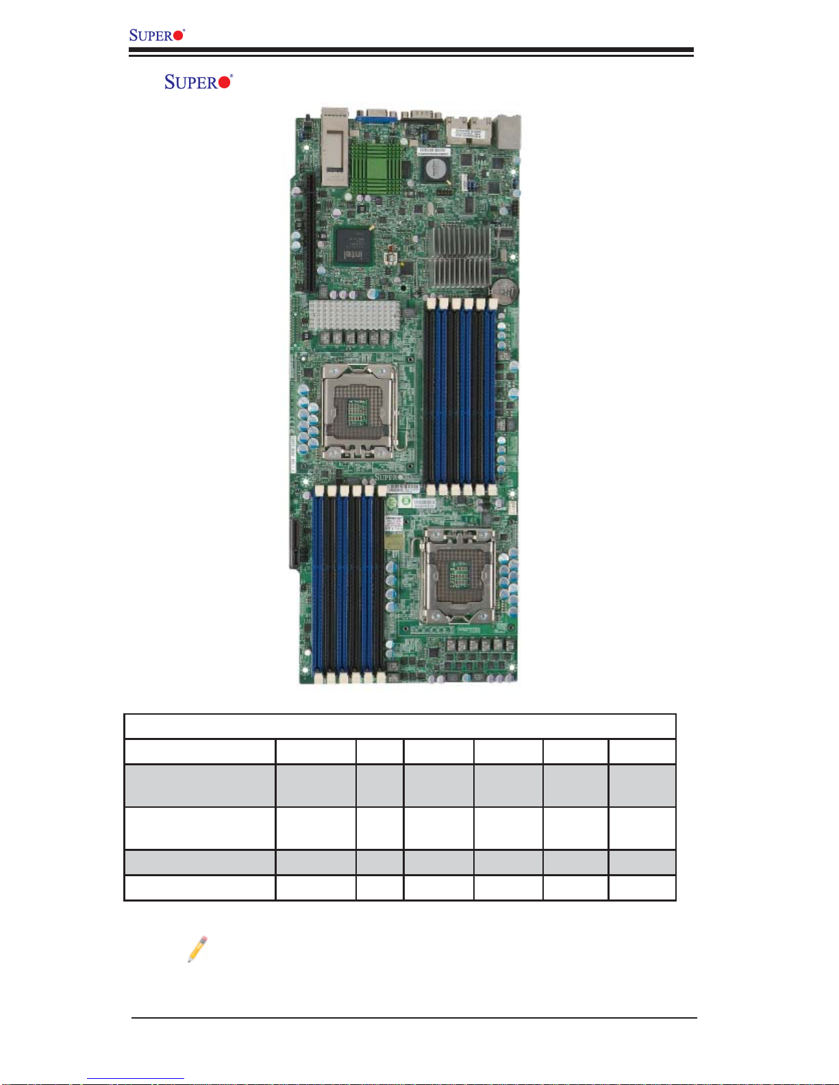
X8DTT-H/-HF/-HIBX/-HIBXF/-HIBQ/-HIBQF User's Manual
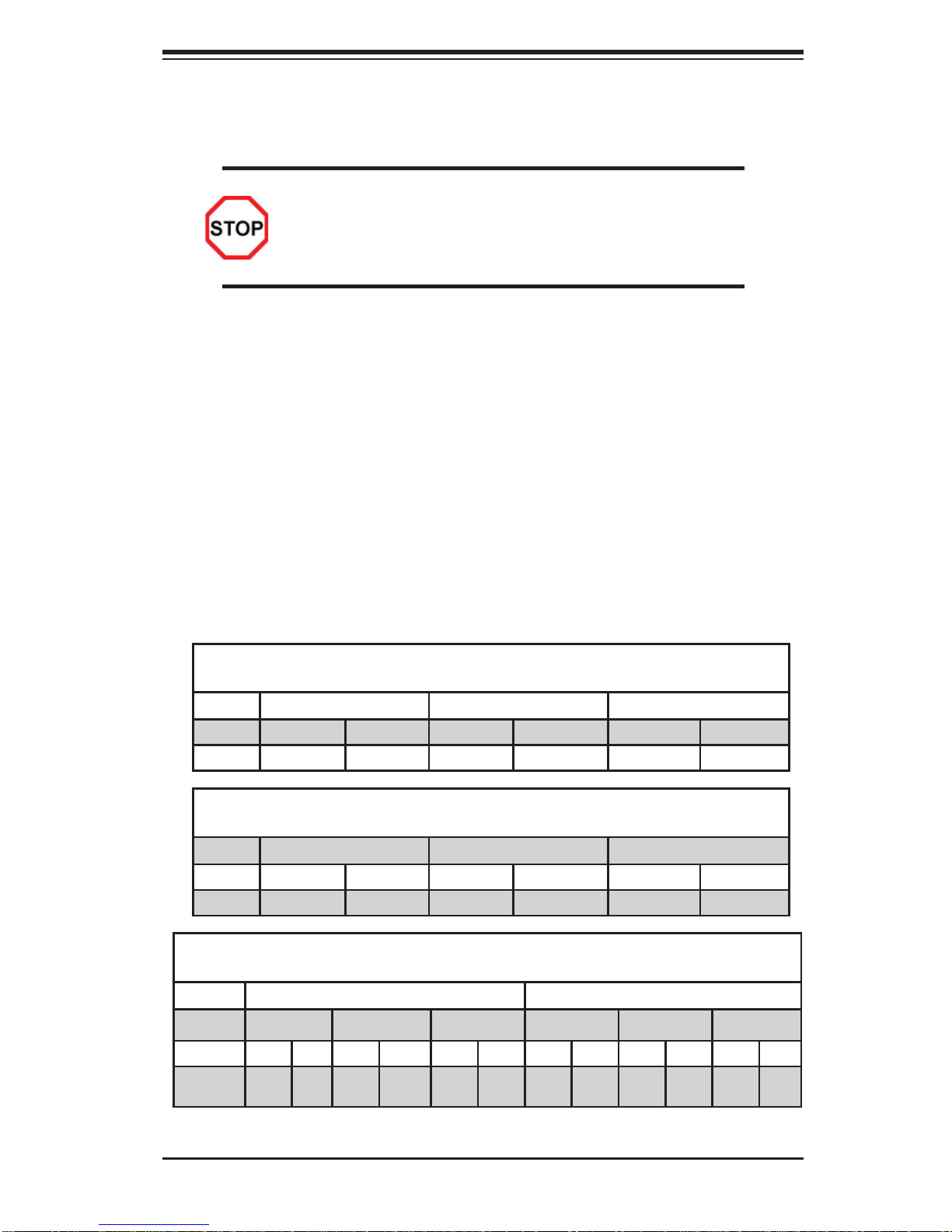
X8DTT-H/-HF/-HIBX/-HIBXF/-HIBQ/-HIBQF Motherboard Image
Model Variations (Differences between X8DTT-H models)
IPMI 2.0 w/ KVM
Over LAN
Infi niBand
Connection
DDR IB No No Yes Yes No No
QDR IB No No No No Yes Yes
Note: The drawings and pictures shown in this manual were based on the
latest PCB Revision available at the time of publishing of the manual. The
motherboard you’ve received may or may not look exactly the same as
the graphics shown in the manual.
X8DTT-H /-HF /-HIBX /-HIBXF /-HIBQ /HIBQF
No Yes No Yes No Yes
No No Yes Yes Yes Yes
1-2
Chapter 1: Introduction
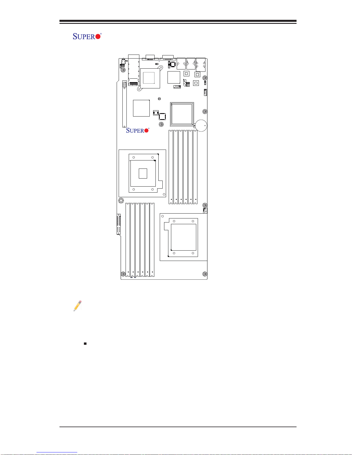
X8DTT-H/-HF/-HIBX/-HIBXF/-HIBQ/-HIBQF Motherboard Layout
LEB2
LEB1
LE4
SW1
JRST1
JWD
JNMI1
Slot 1 PCI-E 2.0 x16
InfinBand
Connector
Intel ICH10R
South Bridge
CPU2
VGA
LE2
JSPK1
InfiniBand
CTRL
JBT1
CLEAR
CMOS
BIOS
X8DTT-H
Rev. 1.3
COM1
JBMC1
Winbond
WPCM450
P2 DIMM1B
LAN2
LAN CTRL1
IPMB
JPG1
JLPC80
Intel 5520 (IOH-36D)
Intel 5500 (IOH-24D)
(For OEM only)
P2 DIMM2B
P2 DIMM1A
P2 DIMM2A
LAN1
JPL1
LAN CTRL2
P2 DIMM3B
USB0/1
IPMI_LAN
PHY
Battery
JBAT1
P2 DIMM3A
JPL2
JUSB2
C384
JUSB2
Notes:
Jumpers not indicated are for test purposes only. For more information on 1.
jumpers or components, refer to Chapter 2.
" " indicates the location of Pin 1.2.
When LE1 LED is on, the onboard power connection is on. Make sure to 3.
unplug the power cables before removing or installing components.
I-SATA1
FP CTRL
JF2
PWR Supply
P1 DIMM3A
P1 DIMM3B
LE3
LE1
P1 DIMM2B
P1 DIMM2A
P1 DIMM1A
P1 DIMM1B
FAN1
CPU1
To use Hot-swap support on the 827 chassis, connect a cable to pins 2~3 on 4.
JPEN1. Close pins 1~2 of JPEN1 with a cap to use regular PWR setting.
To avoid overheating, be sure to provide adequate airfl ow to the system.5.
1-3
X8DTT-H/-HF/-HIBX/-HIBXF/-HIBQ/-HIBQF User's Manual
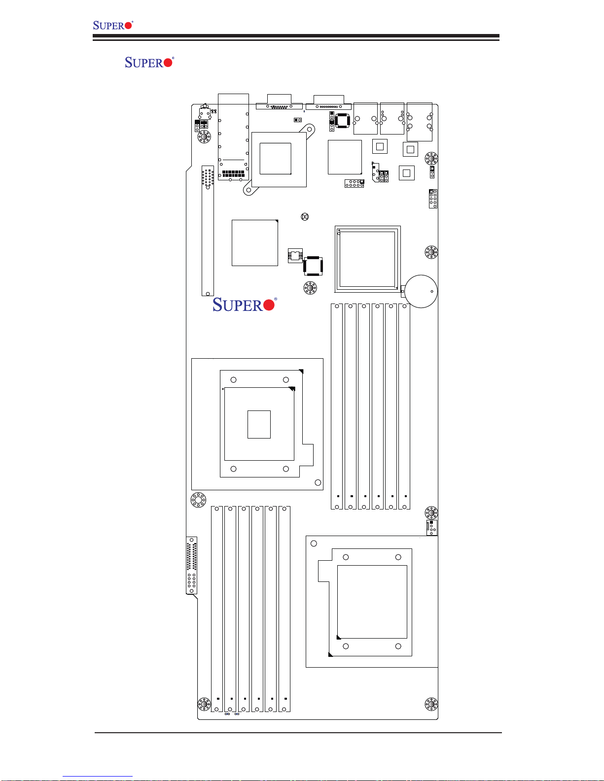
X8DTT-H/-HF/-HIBX/-HIBXF/-HIBQ/-HIBQF Quick Reference
LEB2
LEB1
LE4
SW1
JRST1
JWD
JNMI1
Slot 1 PCI-E 2.0 x16
InfinBand
Connector
Intel ICH10R
South Bridge
VGA
LE2
JSPK1
InfiniBand
CTRL
JBT1
CLEAR
CMOS
BIOS
X8DTT-H
Rev. 1.3
COM1
JBMC1
Winbond
WPCM450
LAN1
LAN2
LAN CTRL1
IPMB
JLPC80
Intel 5520 (IOH-36D)
Intel 5500 (IOH-24D)
(For OEM only)
JPG1
JPL1
LAN CTRL2
USB0/1
IPMI_LAN
PHY
Battery
JBAT1
JPL2
JUSB2
C384
JUSB2
I-SATA1
FP CTRL
JF2
PWR Supply
P1 DIMM3A
P1 DIMM3B
CPU2
P1 DIMM2B
P1 DIMM2A
P1 DIMM1A
P1 DIMM1B
P2 DIMM1A
P2 DIMM1B
P2 DIMM2B
P2 DIMM2A
CPU1
P2 DIMM3A
P2 DIMM3B
FAN1
LE1
LE3
1-4

Chapter 1: Introduction
Quick Reference (See Chapter 2 for Details)
Jumper Description Default Setting
JBT1 CMOS Clear (See Section 2-8)
JPG1 VGA Enable Pins 1-2 (Enabled)
JPL1/JPL2 LAN1/2 Enable Pins 1-2 (Enabled)
JWD Watch Dog Pins 1-2 (Reset)
Connector Description
COM1 COM1 Serial Port
FAN 1 Cooling Fan Header
Infi niBand Infi niBand Connector (X8DTT-HIBX/HIBXF/HIBQ/HIBQF)
IPMB IPMB Header (for an IPMI Card) (X8DTT-HF/-HIBXF/-
HIBQF)
JF2 SMC Proprietary Slot for Power, FP Control & I-SATA
Connections (See Page 2-16)
JNMI1 NMI (Non-Maskable Interrupt) Header
JRST1 Alarm Reset Header
JSPK1 Internal Speaker/Buzzer Header
LAN1/2 Gigabit Ethernet (RJ45) Ports
(IPMI dedicated) LAN LAN (RJ45) Port for IPMI 2.0 (X8DTT-HF/-HIBXF/-
HIBQF)
Slot 1 PCI-E 2.0 x16 slot
SW1 Unit Identifi er Switch
USB 0/1 Universal Serial Bus (USB) Ports 0/1
USB 2/3 (JUSB2) Front Accessible USB connections
VGA Video Port
LED Description
LE1 Onboa rd Stan dby PWR war ning LE D Indic ator
LE2 BMC Heartbeat LED Indicator
LE3 HDD/SATA LED Indicator
LE4 (Rear) Unit Identifi er (UID) LED Indicator
LEB1 Infi niBand Link LED (X8DTT-HIBX/-HIBXF/-HIBQ/-HIBQF)
LEB2 Infi niBand Activity LED (X8DTT-HIBX/-HIBXF/-HIBQ/-HIBQF)
1-5

X8DTT-H/-HF/-HIBX/-HIBXF/-HIBQ/-HIBQF User's Manual
Motherboard Features
CPU
Two Intel•
two full-width Intel QuickPath Interconnect (QPI) links with a total of up to 51.2
GT/s Data Transfer Rate supported (6.4 GT/s per direction)
®
5500 Series (LGA 1366) processors with each processor supporting
Memory
Twelve 240-pin DIMM sockets support up to 48 GB of DDR3 Registered ECC •
or 24 GB of Unbuffered ECC/Non-ECC 1333/1066/800 MHz Memory (with max.
4 GB of Registered ECC and 2 GB of Unbuffered memory per DIMM slot.) (See
Section in Chapter 2 for DIMM Slot Population.)
Chipset
Intel 5520 chipset, including: the 5520 (IOH-36D) and the ICH10R (South •
Bridge).
Note: the 5500 chipset (IOH-24D) is available for OEM only.
Expansion Slot
One PCI-E x16 Gen. 2.0 slot (Slot 1)•
BIOS
32 Mb AMI SPI Flash ROM•
ACPI 1.0/2.0/3.0, Plug and Play (PnP), and USB Keyboard support•
PC Health Monitoring
Onboard voltage monitors for CPU1 VCore, CPU2 VCore, +5Vin, • 12Vcc (V),
VP1 DIMM, VP2 DIMM, +3.3Vcc (V), and Battery Voltage
Fan status monitor with fi rmware control
•
CPU/chass is temper ature moni tors•
I• 2C temperatu re sensin g logic
SDDC support
•
Platfo rm Enviro nment Co ntrol Inte rf ace (PECI) read y•
CPU fan auto - of f in sle ep mode•
CPU slow- dow n on tempe rature over heat•
Pulse Wi dth Mo dulati on (PW M) Fan Contro l•
CPU ther mal tr ip supp or t for pro ces sor pr otecti on, power L ED•
Power-up mod e cont rol for r ecover y fr om AC power l oss•
Auto- switc hing vol tage r egulato r for CPU c ore s•
System over heat /Fan Fail LED I ndic ator and c ontr ol•
System re sourc e aler t vi a Super o Doc tor III•
1-6

Chapter 1: Introduction
ACPI Features
Slow blinking LED for suspend state indicator•
Main switch override mechanism•
ACPI Pow er Ma nag eme nt•
Keyboard Wakeup from Soft-off •
Onboard I/O
Intel ICH10R supports a SATA port (with RAID0, RAID1, RAID10, RAID5 sup-•
ported in the Windows OS Environment and RAID 0, RAID 1, RAID 10 supported
for the Linux OS)
Winbond WPCM450 BMC (Baseboard Management Controller) supports IPMI
•
2.0 with K V M supp or t (For the X8DTT-HF/-HIBXF/-HIBQF only)
Dual Intel 8 2574 Dual- L A N G iga bit Eth er net Co ntr olle rs s uppo r t du al Gi ga - bit
•
LAN ports
Onboard PHY Chip supports IPMI dedicated LAN (For the X8DTT-HF/-HIBXF/-
•
HIBQF only)
One CO M por t
•
Infi niBand Conn ector (For t he X8DT T-HIBX/-HIBXF/ HIBQ/-HIBQF only)•
Up to four U S B 2 . 0 ( U ni ve rsal Se rial Bus) con n e ction s (2 Rear U SB Ports and •
1 Type A Head er w/2 USB c onne ctio ns suppo rte d)
Super I/ O: Winbo nd W83 527HG
•
Other
Console redirection•
Onboa rd Fan Spee d Contr ol by Ther mal Ma nagem ent via BI OS•
CD/Diskette Utilities
BIOS fl ash upgrade utility and device drivers•
Dimensions
Propr ietar y 16.6 4" (L) x 6.80 " (W ) (422.6 6 mm x 172.72 mm)•
1-7
X8DTT-H/-HF/-HIBX/-HIBXF/-HIBQ/-HIBQF User's Manual
#1
#1
#1
A
B
C
DDR3 DIMM
QSFP
#2
#2
#2
A
PROCESSOR#0
B
C
DDR3 DIMM
MT25408
Connect-X IB
PCI-E Gen2/DDR or QDR
(For 36D Only)
PCI-E
x16 Slot
DDR II
VGA CONN
CSI
Port1 Port0
Ports
3,4
Ports
7,8,9,10
PE
PE
4-1
5520/5500
36-D/24-D
5
AD17
PCI
IRQC
REQ1
GNT1
WBD
BMC/VGA
IOH
ESI
DMI
RMII
RTL8201N PHY
PROCESSOR#1
1
Port
2
Port
CLINK
CLINK
ICH10R
LPC
#2
E
DDR3 DIMM
Intel
82574
Intel
82574
4 SATA
Hotswap Connector
LPCIO W83527
ACPI
KBC
#2
#2
DD
E
FF
RJ45
RJ45
AT25
SPI
DF321
#1
#1
#1
DDR3 DIMM
Dedicated LAN
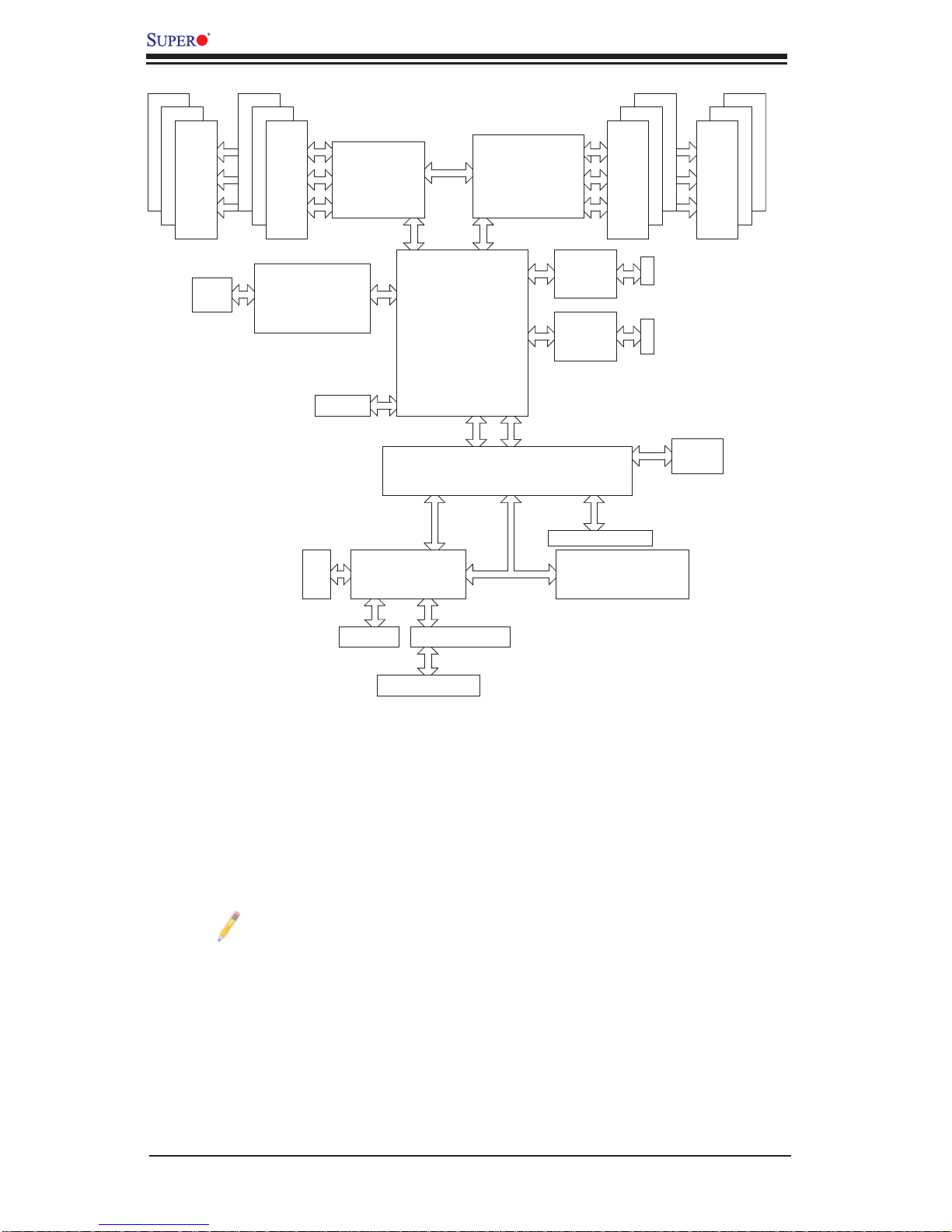
System Block Diagram
Note 1: This is a general block diagram. Please see the previous Mother-
board Features pages for details on the features of each motherboard.
Note 2: Intel 5500 (IOH-24D) is available for OEM only.
1-8

Chapter 1: Introduction
1-2 The 5500 Series Processor Platform
Built upo n the fun ction ality a nd the c apabili ty of th e 550 0 Seri es Proc esso r platform, t he X8DTT-H/ -HF/-HI BX/- HIBXF/-HIB Q/-H IBQF moth erboard pr ovides the
performance and feature set required for dual-processor-based systems optimized
for intensive applications, High Performance Computing (HPC)/Cluster server
platfo r ms. T he 5 5 0 0 Se ri es Pr oc e ss or pl at fo r m co nsi st s of the 5 5 0 0 S er ie s (LGA
1366) processor, the 5520/5500 (IOH-36D/IOH-24D), and the ICH10R (South
Bridg e). W ith the Intel Q uickPath interc onnect (QPI) co ntroller bui lt in, the 550 0
Series Processor platform is the fi rst dual-processing platform that offers the next
generation point-to-point system interconnect interface to replace the current Front
Side Bus Technology, substantially enhancing system performance by utilizing serial lin k interc onnec tions , allowi ng for inc rease d bandw idth an d scal abilit y.
The IOH connects to each processor through an independent QPI (QuickPath
interconnect) link. Each link consists of 20 pairs of unidirectional differential lanes
for tra nsmis sio n and re cei ving i n addit ion t o a dif fer entia l for wa rded c lo ck. A f ull width Q PI link pair p rovide s 84 si gnals. Ea ch proc ess or suppo rt s two Q uickPat h
links, one g oing to th e other pr oce ssor an d the othe r to the 5 520/5 50 0 IOH.
The 552 0/55 00 IO H suppor ts up to 3 6/24 PC I Expre ss Gen 2 lanes pe er-to- peer
read and write transactions. The ICH10R provides multiple PCI-Express SATA
and USB c onne ctio ns.
In addition, the 5500 Series Processor platform also offers a wide range of
RA S (Reliabilit y, Availabili ty and Ser vice ability) featur es. These feat ures inclu de
memor y i nter fa ce ECC, x4 /x8 S ing le Devi ce D ata C or rec tio n (SDD C), Cyclic Re dundancy Check (CRC), parity protection, out-of-band register access via SMBus,
memory mirroring, memory sparing, and Hot-plug support on the PCI-Express
Interface.
Note: Intel 5500 (IOH-24D) is available for OEM only.
Main Features of the 5500 Series Processor and the
5520/5500 Chipset
Four processor cores in each processor with 8MB shared cache among cores•
Two full-width Intel QuickPath interconnect links, up to 6.4 GT/s of data transfer •
rate in each direction
Virtualization Technology, Integrated Management Engine supported
•
Point-to-point cache coherent interconnect, Fast/narrow unidirectional links, and •
Concurrent bi-directional traffi c
1-9

X8DTT-H/-HF/-HIBX/-HIBXF/-HIBQ/-HIBQF User's Manual
1-3 Special Features
Recovery from AC Power Loss
BIOS provides a setting for you to determine how the system will respond when AC
power is lost and then restored to the system. You can choose for the system to
remain powered off (in which case you must press the power switch to turn it back
on) or for it to automatically return to a power- on state. See the Advanced BIOS
Setup section to change this setting. The default setting is Last State.
1-4 PC Health Monitoring
This section describes the PC health monitoring features of the X8DTT-H/-HF/HIBX/-HIBXF/-HIBQ/-HIBQF. All have an onboard System Hardware Monitor chip
that supports PC health monitoring. An onboard voltage monitor will scan these
onboard voltages continuously: CPU1 VCore, CPU2 VCore, +5Vin, 12Vcc (V),
VP1 DIMM, VP2 DIMM, +3.3Vcc (V), and Battery Voltage. Once a voltage becomes
unstable, a warning is given or an error message is sent to the screen. Users can
adjust the voltage thresholds to defi ne the sensitivity of the voltage monitor.
Fan Status Monitor with Firmware Control
The PC health monitor can check the RPM status of the cooling fans. The onboard
CPU and chassis fans are controlled by Thermal Management via BIOS (under
Hardware Monitoring in the Advanced Setting).
Environmental Temperature Control
The thermal control sensor monitors the CPU temperature in real time and will turn
on the thermal control fan whenever the CPU temperature exceeds a user-defi ned
threshold. The overheat circuitry runs independently from the CPU. Once it detects
that the CPU temperature is too high, it will automatically turn on the thermal fan
control to prevent any overheat damage to the CPU. The onboard chassis thermal
circuitry can monitor the overall system temperature and alert users when the chassis temperature is too high.
To avoid possible system overheating, please be sure to provide adequate
airfl ow to your system.
System Resource Alert
This feature is available when used with Supero D octor III in the Windows OS
environment or used with Supero Doctor II in Linux. Supero Doctor is used to
notif y the user of cer tain system events. For example, you can also confi gure
1-10

Chapter 1: Introduction
Supero Doctor to provide you with warnings when the system temperature, CPU
temperat ures, volt ages a nd fan spe eds go beyon d a pre- defi ned range.
1-5 ACPI Features
ACPI stands for Advanced Confi guration and Power Interface. The ACPI specifi ca-
tion defi nes a fl exible and abstract hardware interface that provides a standard
way to integrate power management features throughout a PC system, including
its hardware, operating system and application software. This enables the system
to automatically turn on and off peripherals such as CD-ROMs, network cards, hard
disk drives and printers.
In addition to enabling operating system-directed power management, ACPI
provides a generic system event mechanism for Plug and Play and an operating
system-independent interface for confi guration control. ACPI leverages the Plug
and Play BIOS data structures while providing a processor architecture-independent
implementation that is compatible with Windows XP/Windows 2003/Windows 2008/
Windows Vista Operating Systems.
Slow Blinking LED for Suspend-State Indicator
When the CPU goes into a suspend state, the chassis power LED will start blinking
to indicate that the CPU is in suspend mode. When the user presses any key, the
CPU will wake-up and the LED will automatically stop blinking and remain on.
Main Switch Override Mechanism
When an ATX power supply is used, the power button can function as a system
suspend button to make the system enter a SoftOff state. The monitor will be
suspended and the hard drive will spin down. Pressing the power button again
will cause the whole system to wake-up. During the SoftOff state, the ATX power
supply provides power to keep the required circuitry in the system "alive." In case
the system malfunctions and you want to turn off the power, just press and hold
the power button for 4 seconds. This option can be set in the Power section of the
BIOS Setup routine.
1-6 Power Supply
As with all computer products, a stable power source is necessary for proper and
reliable operation. It is even more important for processors that have high CPU
clock rates.
It is strongly recommended that you use a high quality power supply that meets ATX
power supply Specifi cation 2.02 or above. It must also be SSI compliant (For more
1-11

X8DTT-H/-HF/-HIBX/-HIBXF/-HIBQ/-HIBQF User's Manual
information, please refer to the web site at http://www.ssiforum.org/). Additionally, in
areas where noisy power transmission is present, you may choose to install a line
fi lter to shield the computer from noise. It is recommended that you also install a
power surge protector to help avoid problems caused by power surges.
Note: The X8DTT-H/-HF/-HIBX/-HIBXF/-HIBQ/-HIBQF supports proprietary power connectors. Please refer to Page 2-16 for detailed information
on power supply for the motherboard.
1-7 Overview of the Winbond WPCM450 Controller
The Winbond WPCM450, a Baseboard Management Controller (BMC), supports
the 2D/VGA-compatible Graphics Core with the PCI interface, Virtual Media, and
Keyboard/Video/Mouse (KVM) Redirection modules.
The WPCM450 BMC interfaces with the host system via a PCI interface to communicate with the graphics core. It supports USB 2.0 and 1.1 for remote keyboard/
mouse/virtual media emulation. It also provides LPC interface to control Super IO
functions. The WPCM450 is connected to the network via an external Ethernet
PHY module.
The WPCM450 communicates with onboard components via six SMBus interfaces,
fan control, Platform Environment Control Interface (PECI) buses.
Note: For more information on IPMI confi guration, please refer to the
Embedded IPMI User's Guide posted on our website @ http://www.supermicro.com/support/manuals/.
1-12

Chapter 2: Installation
Chapter 2
Installation
2-1 Static-Sensitive Devices
Electrostatic Discharge (ESD) can damage electronic com ponents. T o prevent damage to your system board, it is important to handle it very carefully. The following
measures are generally suffi cient to protect your equipment from ESD.
Precautions
Use a grounded wrist strap designed to prevent static discharge.•
Touch a grounded metal object before removing the board from the antistatic •
bag.
Handle the board by its edges only; do not touch its components, peripheral
•
chips, memory modules or gold contacts.
When handling chips or modules, avoid touching their pins.
•
Put the motherboard and peripherals back into their antistatic bags when not •
in use.
For grounding purposes, make sure your computer chassis provides excellent
•
conductivity between the power supply, the case, the mounting fasteners and
the motherboard.
Use only the correct type of onboard CMOS battery as specifi ed by the
•
manufacturer. Do not install the onboard battery upside down to avoid possible
explosion.
Unpacking
The motherboard is shipped in antist atic packag i n g t o avo id static da m a ge. When
unpacking the board, make sure the person handling it is static protected.
2-1
X8DTT-H/-HF/-HIBX/-HIBXF/-HIBQ/-HIBQF User's Manual
2-2 Motherboard Installation
All motherboards have standard mounting holes to fi t different types of chassis.
Make sure that the locations of all the mounting holes for both motherboard and
chassis match. Although a chassis may have both plastic and metal mounting
fasteners, metal ones are highly recommended because they ground the motherboard to the chassis. Make sure that the metal standoffs click in or are screwed in
tightly. Then use a screwdriver to secure the motherboard onto the motherboard
tray. Note: Some components are very close to the mounting holes. Please take
precautionary measures to prevent damage to these components when installing
the motherboard to the chassis.
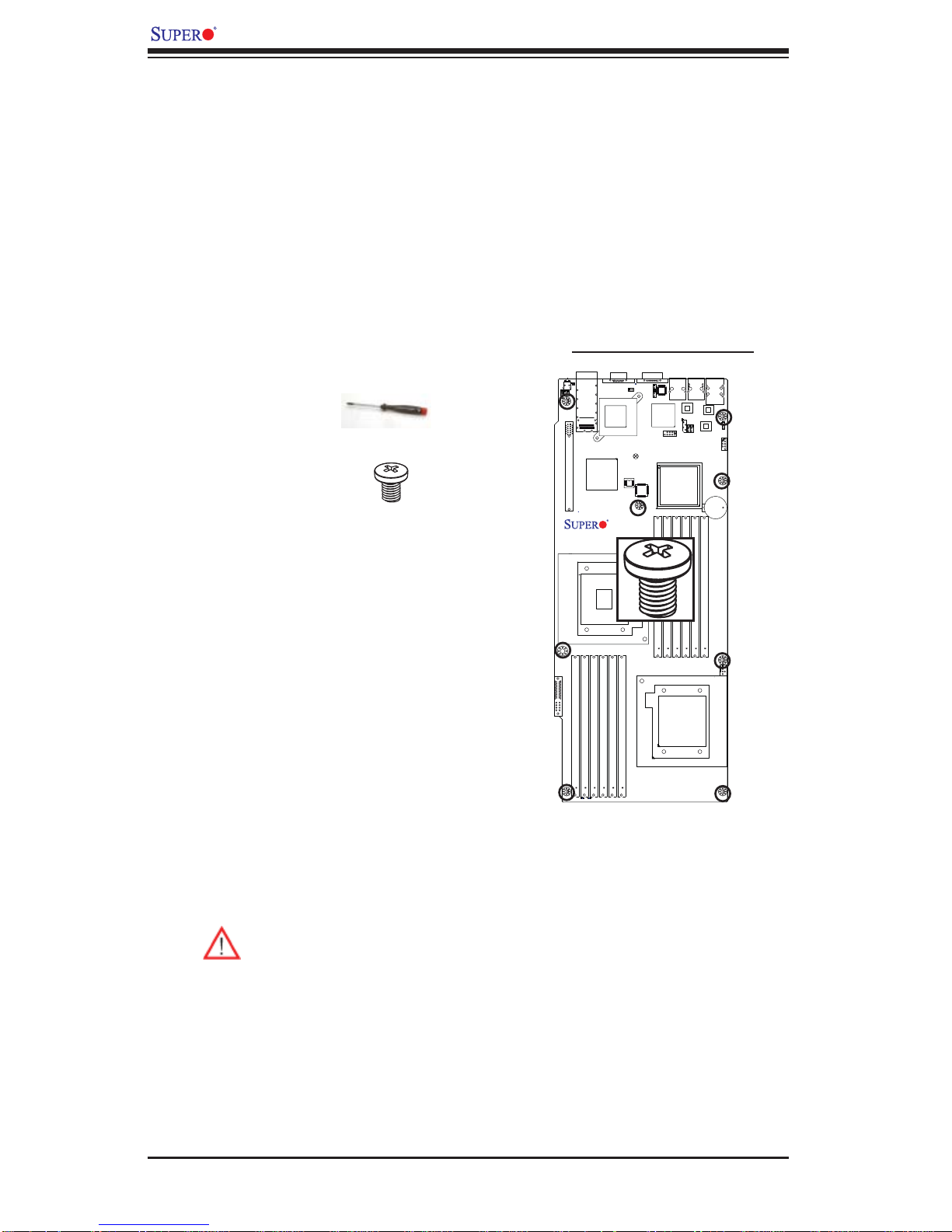
Tools Needed
1. Phillips Screwdriver
2. Pan head #6 screws
Locations of Mounting Holes
X8DTT-H
Installation Instructions
Rev. 1.3
Install the IO shield into the chassis. 1.
Locate the mounting holes on the mother-2.
board. Refer to the layout above for mounting hole locations.
Locate the matching mounting holes on the 3.
chassis. Align the mounting holes on the
motherboard against the mounting holes on
the chassis.
Install standoffs in the chassis as needed.4.
Install the motherboard into the chassis carefully to avoid damage to mother-5.
board components.
Warning: To avoid damaging the motherboard and its components, please
do not apply any force greater than 8 lb/sq.in (8 lbs. per square inch) when
installing a screw into a mounting hole.
Insert a Pan head #6 screw into a mounting hole on the motherboard and its 6.
matching mounting hole on the chassis, using a Phillips screwdriver.
Repeat Step 4 to insert #6 screws to all mounting holes.7.
Make sure that the motherboard is securely placed on the chassis.8.
2-2
2-3 Processor and Heatsink Installation
!
When handling the processor package, avoid placing direct pressure on
the label area of the fan.
Notes:
Always connect the power cord last and always remove it before adding, re-1.
moving or changing any hardware components. Make sure that you install the
processor into the CPU socket before you install the CPU heatsink.
Make sure to install the motherboard into the chassis before you install the 2.
CPU heatsink and heatsink fans.
When purchasing a motherboard without a 5500 Series processor pre-3.
installed, make sure that the CPU socket plastic cap is in place, and none of
the CPU socket pins are bent; otherwise, contact the retailer immediately.
Chapter 2: Installation
Refer to the M B Features S ecti on for mo re deta ils on CPU s uppor t.4.
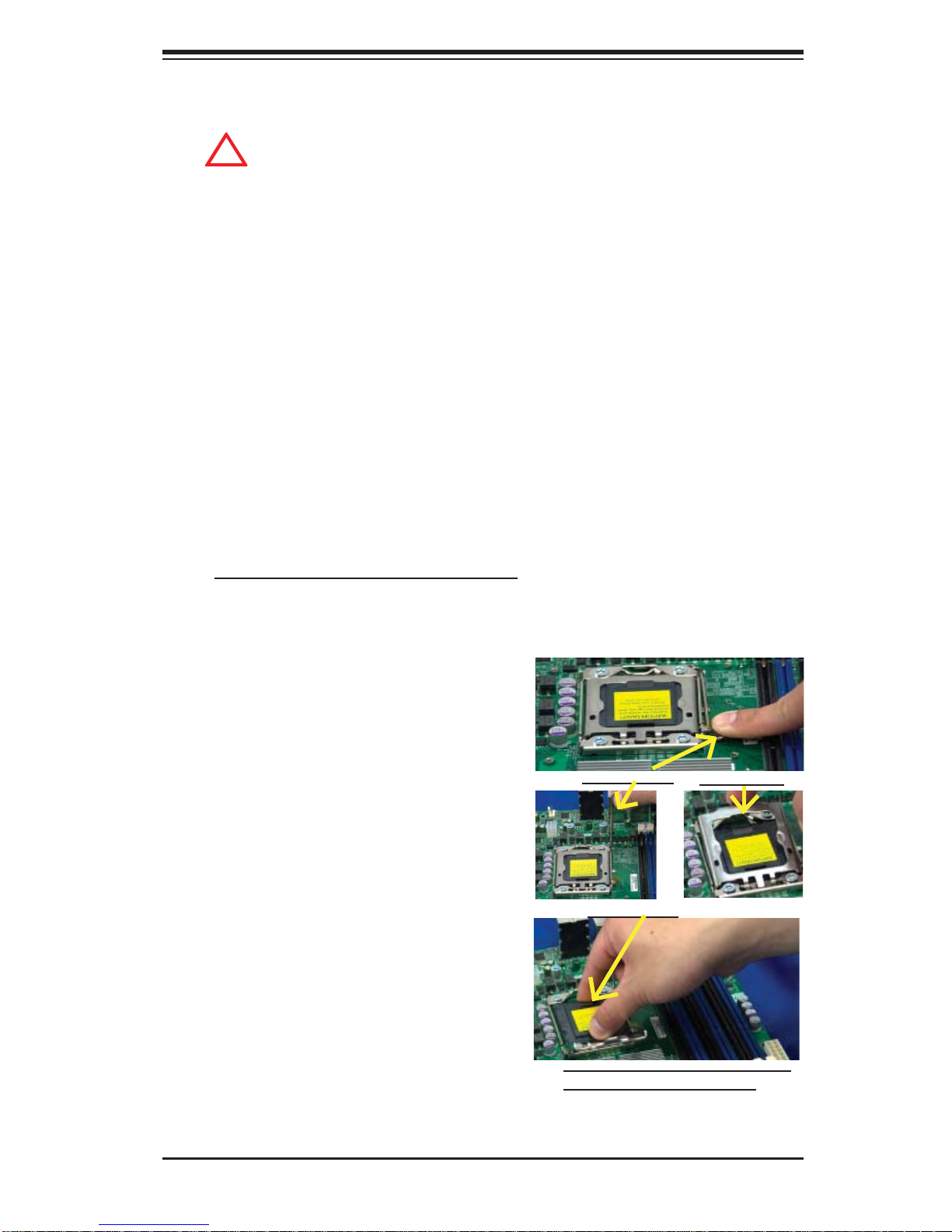
Installing an LGA 1366 Processor
Press the socket clip to release 1.
the load plate, which covers the
CPU socket, from its locking
position.
Gently lift the socket clip to 2.
open the load plate.
Hold the plastic cap at its north 3.
and south center edges to remove it from the CPU socket.
Socket Clip
Plastic Cap
Load Plate
Hold the north & south edges of
the plastic cap to remove it
2-3

X8DTT-H/-HF/-HIBX/-HIBXF/-HIBQ/-HIBQF User's Manual
After removing the plastic cap, using 4.
your thumb and the index fi nger,
hold the CPU at the north and south
center edges.
Align the CPU key, the semi-circle 5.
cutout, against the socket key, the
notch below the gold color dot on
the side of the socket.
Once both the CPU and the socket 6.
are aligned, carefully lower the CPU
straight down into the socket. (Do
not rub the CPU against the surface
Socket Keys CPU CPU SocketLoad Plate
of the socket or its pins to avoid
damaging the CPU or the socket.)
With the CPU inside the socket, in-7.
spect the four corners of the CPU to
make sure that the CPU is properly
installed.
Once the CPU is securely seated 8.
on the socket, lower the CPU load
plate to the socket.
Use your thumb to gently push the 9.
socket clip down to the clip lock.
Warning: Please save the plastic ca p. The mot her board m ust
be shipped with the plastic cap
properly installed to protect the
CPU socket pins. Shipment
without the plastic cap properly
installed will cause damage to
the socket pins.
CPU Keys
2-4
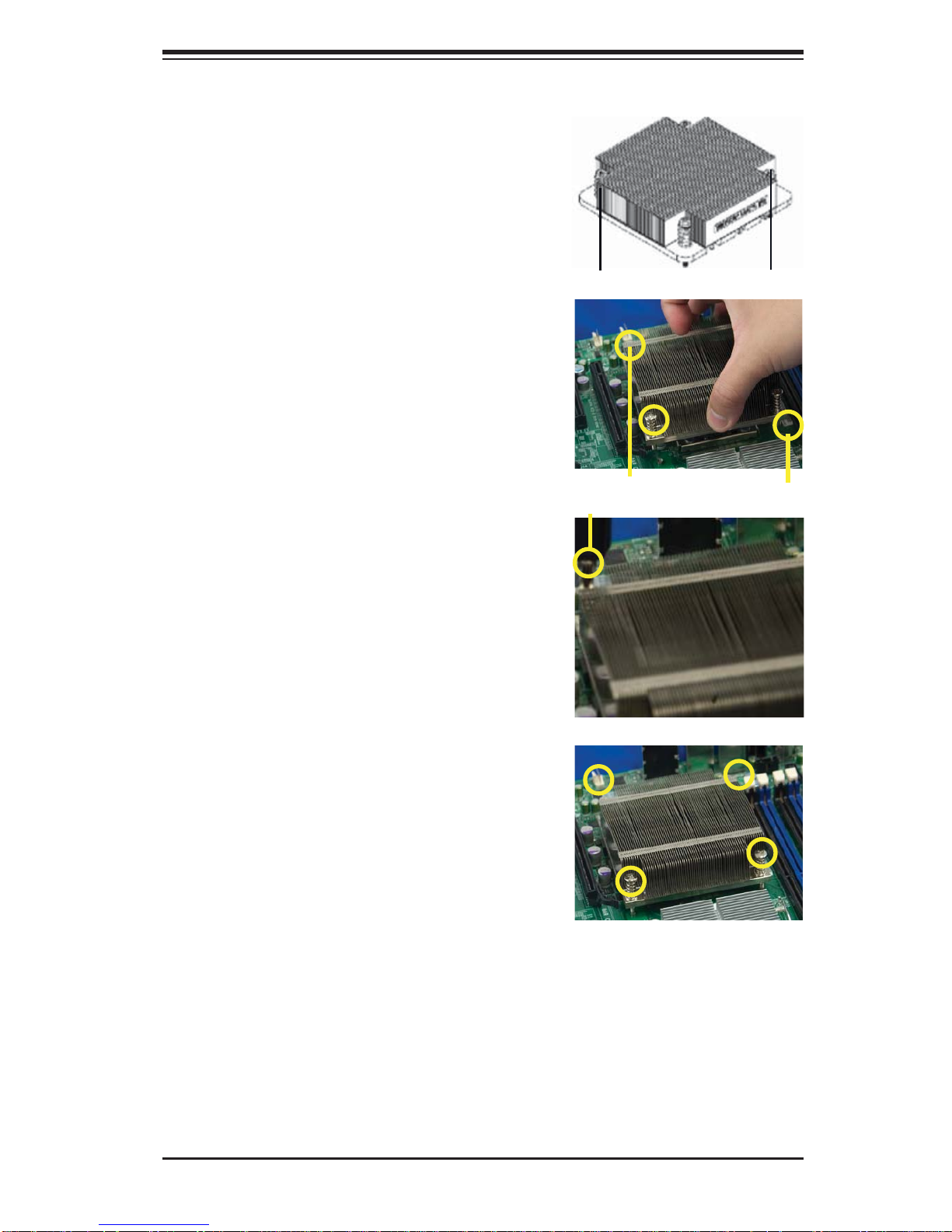
Installing a CPU Heatsink
Do not apply any thermal 1.
grease to the heatsink or the
CPU die because the required
amount has already been applied.
Chapter 2: Installation
Place the heatsink on top of the 2.
CPU so that the four mounting
holes are aligned with those on
the retention mechanism.
3. Install two diagonal screws (ie
the #1 and the #2 screws) and
tighten them until just snug (-do
not fully tighten the screws to
avoid possible damage to the
CPU.)
Screw#1
Screw#1
Install Screw#1
Screw#2
Screw#2
4. Finish the installation by fully
tightening all four screws.
2-5
X8DTT-H/-HF/-HIBX/-HIBXF/-HIBQ/-HIBQF User's Manual
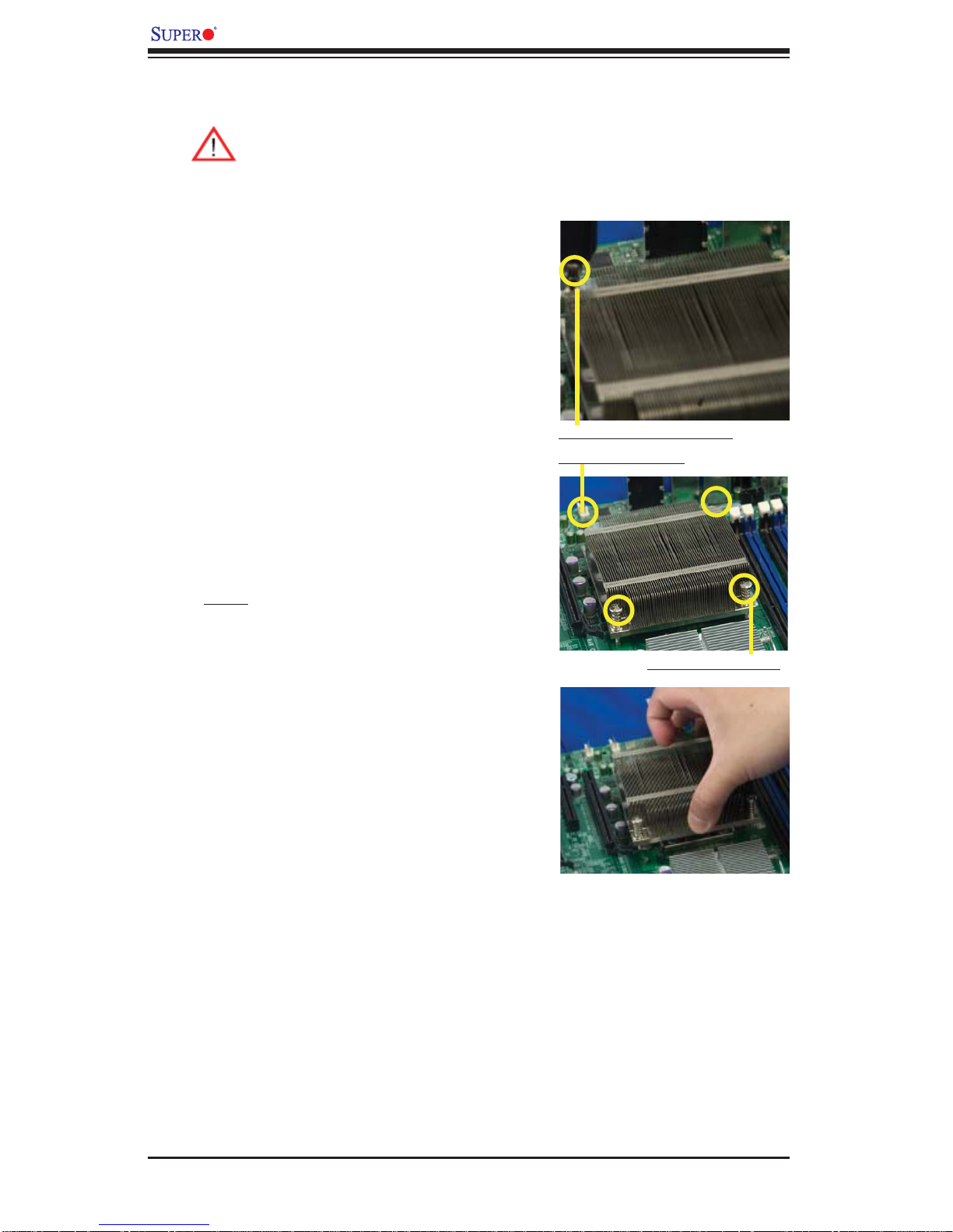
Removing the Heatsink
Warni ng: We do not recommend that the CPU or the heatsink be removed. However, if you do need to remove the heatsink, please follow
the inst ructions be low to uninstall th e heatsink and prevent da mage to
the CPU or ot her co mpone nts.
Unplug the power cord from the 1.
power supply.
Disconnect the heatsink fan 2.
wires from the CPU fan header.
Using a screwdriver, loosen and 3.
remove the heatsink screws
from the motherboard in the sequence as show in the picture
on the right.
Using a screwdriver to
remove Screw#1
Hold the heatsink as shown 4.
in the picture on the right and
gently wriggle the heatsink to
loosen it from the CPU. (Do not
use excessive force when wriggling the heatsink.)
Once the heatsink is loosened, 5.
remove it from the CPU socket.
To reinstall the CPU and the 6.
heatsink, clean the surface of
the CPU and the heatsink to get
rid of the old thermal grease.
Reapply the proper amount of
thermal grease on the surface
before reinstalling them on the
motherboard.
Remove Screw#2
2-6
Chapter 2: Installation
2-4 Memory Installation
Note: Check the S uper micro we b site for r ecom mende d memor y mo dules .
CAUTION
Exercise extreme care when installing or removing DIMM
module s to prevent any po ssib le damag e. Also n ote that th e
memor y is i nterl eaved to imp rove per fo rman ce (See ste p 1).
DIMM Installation
Insert the desired number of DIMMs into the memory slots, starting with 1.
P1-DIMM 1A. For best memory performance, please install memory modules
of the same type and same speed on the memory slots as indicated on the
tables below. (See the Memory Installation Table Below.)
Insert each DIMM module vertically into its slot. Pay attention to the notch 2.
along the bottom of the module to prevent inserting the DIMM module incorrectly.
Gently press down on the DIMM module until it snaps into place in the slot. 3.
Repeat for all modules.
Memory Population for Optimal Performance
-For a motherboard with One CPU (CPU1) installed
Branch 0 Branch 1 Branch 2
3 DIMMs P1 DIMM1A P1 DIMM2A P1 DIMM3A
6 DIMMs P1 DIMM1A P1 DIMM1B P1 DIMM2A P1 DIMM2B P1 DIMM3A P1 DIMM3B
Memory Population for Optimal Performance
-For a motherboard with One CPU (CPU2) installed
Branch 0 Branch 1 Branch 2
3 DIMMs P2 DIMM1A P2 DIMM2A P2 DIMM3A
6 DIMMs P2 DIMM1A P2 DIMM1B P2 DIMM2A P2 DIMM2B P2 DIMM3A P2 DIMM3B
Memory Population for Optimal Performance
-For a motherboard with Two CPUs installed
CPU1 CPU2
Branch 0 Branch 1 Branch 3 Branch 0 Branch 1 Branch 3
6 DIMMs 1A 2A 3A 1A 2A 3A
12
DIMMs
1A 1B 2A 2B 3A 3B 1A 1B 2A 2B 3A 3B
2-7
X8DTT-H/-HF/-HIBX/-HIBXF/-HIBQ/-HIBQF User's Manual
Memory Support
The X8DTT-H Series motherboard supports up to 48 GB of Registered ECC or
24 GB of Unbuffered ECC/Non-ECC DDR3 1333 MHz/1066 MHz/800 MHz in 12
DIMMs (with max. 4 GB of Registered ECC and 2 GB of Unbuffered memory per
DIMM slot.).
Note: memory speed support depends on the type of CPU used on the
motherboard.
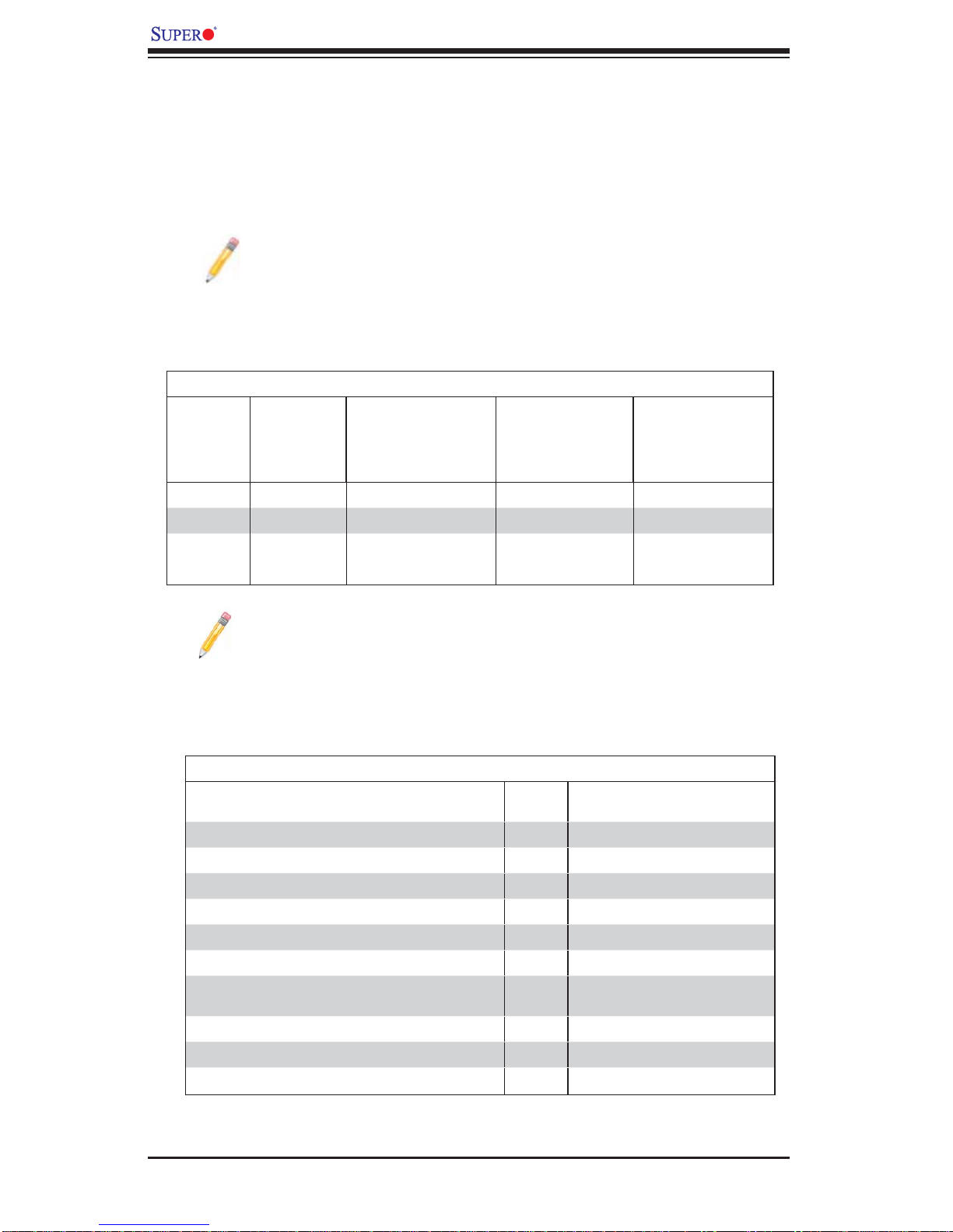
DIMM Module Population Confi guration
For memor y to wor k pro perl y, follow the tab les be low for me mor y inst allati on:
DIMM Population Table
DIMM
Slots per
Channel
2 1 Reg. DDR3 ECC 800,1066,1333 SR or DR
2 1 Reg. DDR3 ECC 800,1066 QR
2 2 Reg. DDR3 ECC 800,1066 Mixing SR, DR
2 2 Reg. DDR3 ECC 800 Mixing SR, DR,QR
DIMMs
Populated
per Channel
DIMM Type (Reg.=
Registered)
Speeds (in MHz) Ranks per DIMM
(any combination;
SR=Single Rank,
DR=Dual Rank,
QR=Quad Rank)
Note 1: Due to OS limitations, some operating systems may not show
more than 4 GB of memory.
Note 2: Due to memory allocation to system devices, the amount of mem-
ory that remains available for operational use will be reduced when 4 GB
of R AM is us ed. The r educt ion in m emor y avai labili ty is di spro por tio nal.
Possible System Memory Allocation & Availability
System Device Size Physical Memory Available
Firmware Hub fl ash memory (System BIOS) 1 MB 3.99 GB
Local APIC 4 KB 3.99 GB
Area Reserved for the chipset 2 MB 3.99 GB
I/O APIC (4 Kbytes) 4 KB 3.99 GB
PCI Enumeration Area 1 256 MB 3.76 GB
PCI Express (256 MB) 256 MB 3.51 GB
PCI Enumeration Area 2 (if needed) -Aligned on 256-M
boundaryVGA Memory 16 MB 2.85 GB
TSEG 1 MB 2.84 GB
Memory available for the OS & other applications 2.84 GB
512 MB 3.01 GB
(4 GB Total System Memory)
2-8
 Loading...