

Page 1

®
SUPER
X8DA3
X8DAi
(Preliminary Draft)
USER’S MANUAL
Revision 1.0
Page 2

The information in this User’s Manual has been carefully reviewed and is believed to be accurate.
The vendor assumes no responsibility for any inaccuracies that may be contained in this document,
makes no commitment to update or to keep current the information in this manual, or to notify any
person or organization of the updates. Please Note: For the most up-to-date version of this
manual, please see our web site at www.supermicro.com.
Super Micro Computer, Inc. ("Supermicro") reserves the right to make changes to the product
described in this manual at any time and without notice. This product, including software, if any,
and documentation may not, in whole or in part, be copied, photocopied, reproduced, translated or
reduced to any medium or machine without prior written consent.
IN NO EVENT WILL SUPERMICRO BE LIABLE FOR DIRECT, INDIRECT, SPECIAL, INCIDENTAL,
SPECULATIVE OR CONSEQUENTIAL DAMAGES ARISING FROM THE USE OR INABILITY TO
USE THIS PRODUCT OR DOCUMENTATION, EVEN IF ADVISED OF THE POSSIBILITY OF
SUCH DAMAGES. IN PARTICULAR, SUPERMICRO SHALL NOT HAVE LIABILITY FOR ANY
HARDWARE, SOFTWARE, OR DATA STORED OR USED WITH THE PRODUCT, INCLUDING THE
COSTS OF REPAIRING, REPLACING, INTEGRATING, INSTALLING OR RECOVERING SUCH
HARDWARE, SOFTWARE, OR DATA.
Any disputes arising between manufacturer and customer shall be governed by the laws of Santa
Clara County in the State of California, USA. The State of California, County of Santa Clara shall
be the exclusive venue for the resolution of any such disputes. Super Micro's total liability for all
claims will not exceed the price paid for the hardware product.
FCC Statement: This equipment has been tested and found to comply with the limits for a Class B
digital device pursuant to Part 15 of the FCC Rules. These limits are designed to provide reasonable
protection against harmful interference in a residential installation. This equipment generates,
uses, and can radiate radio frequency energy and, if not installed and used in accordance with the
manufacturer’s instruction manual, may cause interference with radio communications. However,
there is no guarantee that interference will not occur in a particular installation. If this equipment
does cause harmful interference to radio or television reception, which can be determined by turning
the equipment off and on, you are encouraged to try to correct the interference by one or more
of the following measures: Reorient or relocate the receiving antenna. Increase the separation
between the equipment and the receiver. Connect the equipment into an outlet on a circuit different
from that to which the receiver is connected. Consult the dealer or an experienced radio/television
technician for help.
California Best Management Practices Regulations for Perchlorate Materials: This Perchlorate
warning applies only to products containing CR (Manganese Dioxide) Lithium coin cells. “Perchlorate
Material-special handling may apply. See www.dtsc.ca.gov/hazardouswaste/perchlorate”
WARNING: Handling of lead solder materials used in this
product may expose you to lead, a chemical known to
the State of California to cause birth defects and other
reproductive harm.
Manual Revision 1.0 (Draft 3)
Release Date: April 28 2008
Unless you request and receive written permission from Super Micro Computer, Inc., you may not
copy any part of this document.
Information in this document is subject to change without notice. Other products and companies
referred to herein are trademarks or registered trademarks of their respective companies or mark
holders.
Copyright © 2008 by Super Micro Computer, Inc.
All rights reserved.
Printed in the United States of America
Page 3
Preface
About This Manual
This manual is written for system integrators, PC technicians and knowledgeable
PC users. It provides information for the installation and use of the
X8DAi motherboard. The
platform, the fi rst dual-processing platform that supports the Intel QuickPath Inter-
connect Technology, providing the next generation point-to-point system interface,
replacing the current Front Side Bus. With the Tylersburg-EP platform built-in,
the X8DA3/X8DAi offers substantial enhancement in system performance with
increased bandwidth and unprecedented scalability optimized for workstations,
high-end CAD systems and intensive applications. Please refer to our web site
(http://www.supermicro.com/products/) for updates on supported processors. This
product is intended to be professionally installed.
X8DA3/X8DAi supports the Intel Tylersburg-EP
Preface
X8DA3/
Manual Organization
Chapter 1 describes the features, specifi cations and performance of the mother-
board and provides detailed information about the chipset.
Chapter 2 provides hardware installation instructions. Read this chapter when
installing the processor, memory modules and other hardware components into
the system. If you encounter any problems, see Chapter 3, which describes
troubleshooting procedures for the video, the memory and the system setup stored
in the CMOS.
Chapter 4 includes an introduction to BIOS and provides detailed information on
running the CMOS Setup utility.
Appendix A lists BIOS POST Error Codes. Appendix B and Appendix C provide
the Windows OS and Other Software Installation Instructions.
Conventions Used in the Manual
Special attention should be given to the following symbols for proper installation and
to prevent damage done to the components or injury to yourself:
Danger/Caution: Instructions to be strictly followed to prevent catastrophic
system failure or to avoid bodily injury.
Warning: Important information given to ensure proper system installation
or to prevent damage to the components.
Note: Additional Information given to differentiate various models or to
ensure correct system setup.
iii
Page 4
X8DA3/X8DAi User's Manual
Table of Contents
Preface
About This Manual ........................................................................................... iii
Manual Organization ........................................................................................ iii
Conventions Used in the Manual ....................................................................... iii
Chapter 1: Introduction
1-1 Overview .................................................................................................. 1-1
1-2 Checklist ................................................................................................. 1-1
Contacting Supermicro ............................................................................. 1-2
X8DA3/X8DAi Image ................................................................. 1-3
X8DA3/X8DAi Layout ................................................................ 1-4
Quick Reference ...................................................................................... 1-5
Motherboard Features ................................................................................ 1-6
Intel Tylersburg-E System Block Diagram ............................................... 1-8
1-3 Chipset Overview ................................................................................... 1-9
1-4 Special Features ................................................................................... 1-10
1-5 PC Health Monitoring ............................................................................ 1-10
1-6 ACPI Features ...................................................................................... 1-11
1-7 Power Supply ....................................................................................... 1-12
1-8 Super I/O ................................................................................................ 1-13
Chapter 2: Installation
2-1 Static-Sensitive Devices ......................................................................... 2-1
Precautions ................................................................................................ 2-1
Unpacking ................................................................................................ 2-1
2-2 Processor and Heatsink Installation ....................................................... 2-2
2-3 Installing DIMMs ..................................................................................... 2-6
2-4 Control Panel Connectors and IO Ports ................................................. 2-9
1. Back Panel Connectors/IO Ports .............................................................. 2-8
2. Front Control Panel ................................................................................. 2-10
3. Front Control Panel Pin Defi nitions ..........................................................2-11
NMI Button ..............................................................................................2-11
Power LED ..............................................................................................2-11
HDD LED .............................................................................................. 2-12
NIC1/NIC2 LED ..................................................................................... 2-12
Overheat/Fan Fail LED ......................................................................... 2-13
Power Fail LED ........................................................................................ 2-13
Reset Button ......................................................................................... 2-14
vi
Page 5

Table of Contents
Power Button .......................................................................................... 2-14
2-5 Connecting Cables ............................................................................... 2-15
ATX Power Connector .......................................................................... 2-15
Processor Power Connector ................................................................. 2-15
Universal Serial Bus (USB0/1) ................................................................ 2-16
Chassis Intrusion .................................................................................... 2-16
Fan Headers .......................................................................................... 2-17
Keylock ..................................................................................................... 2-17
ATX PS/2 Keyboard and Mouse Ports ..................................................... 2-18
Serial Ports ............................................................................................. 2-18
Wake-On-LAN .......................................................................................... 2-19
Overheat LED/Fan Fail ............................................................................ 2-19
GLAN (Ethernet Ports) ............................................................................. 2-20
T-SGPIO Headers .................................................................................... 2-20
Power SMB Connector ............................................................................. 2-21
IPMB I
2
C SMB Connector ........................................................................ 2-21
High Defi nition Audio ................................................................................ 2-22
CD Header ............................................................................................... 2-22
Front Panel Audio ..................................................................................... 2-23
2-6 Jumper Settings .................................................................................... 2-24
Explanation of Jumpers ......................................................................... 2-24
GLAN Enable/Disable ............................................................................ 2-24
Clear CMOS ............................................................................................. 2-25
Watch Dog ................................................................................................ 2-25
2
I
C Bus to PCI-X/PCI-Exp. Slots Enable/Disable ..................................... 2-26
2
I
C Bus to PCI-X/PCI-X Slots Enable/Disable ......................................... 2-26
SAS Enable .............................................................................................. 2-27
SAS RAID Enable .................................................................................... 2-27
1394_1/1394_2 Enable ............................................................................ 2-28
2-7 Onboard Indicators ............................................................................... 2-29
GLAN LEDs .............................................................................................. 2-29
Onboard Power LED ................................................................................ 2-29
SAS LED Indicators ................................................................................. 2-30
2-8 Floppy, SIMSO, Serial ATA and Hard Disk Drive Connections ........... 2-31
Floppy Connector .................................................................................... 2-31
Serial ATA Ports ....................................................................................... 2-32
SIMLP IPMI Slot ...................................................................................... 2-32
Chapter 3: Troubleshooting
3-1 Troubleshooting Procedures ................................................................... 3-1
vii
Page 6
X8DA3/X8DAi User's Manual
Before Power On ....................................................................................... 3-1
No Power ................................................................................................... 3-1
No Video .................................................................................................. 3-2
Losing the System’s Setup Confi guration ................................................ 3-2
Memory Errors ........................................................................................... 3-2
3-2 Technical Support Procedures ................................................................ 3-3
3-3 Frequently Asked Questions .................................................................. 3-3
3-4 Returning Merchandise for Service ......................................................... 3-4
Appendices
Appendix A: BIOS POST Error Codes ............................................................ A-1
Appendix B: Installing the Windows OS .........................................................B-1
Appendix C: Installing Other Software Programs and Drivers .......................C-1
viii
Page 7

Chapter 1: Introduction
Chapter 1
Introduction
1-1 Overview
Checklist
Congratulations on purchasing your computer motherboard from an acknowledged
leader in the industry. Supermicro boards are designed with the utmost attention to
detail to provide you with the highest standards in quality and performance. Check
that the following items have all been included with your motherboard. If anything
listed here is damaged or missing, contact your retailer.
The following items are included in the retail box.
One (1) Supermicro Mainboard
•
Two (2) SAS cable for SATA/SAS Backplane (CBL-0097L-02) (For X8DA3)
•
One (1) fl oppy ribbon cable (CBL-0022L)
•
Four (4) Serial ATA cables (CBL-0044Lx4) (For X8DA3)
•
Six (6) Serial ATA cables (CBL-0044Lx6) (For X8DAi)
•
One (1) I/O backpanel shield (MCP-260-74301-001)
•
One (1) Supermicro CD containing drivers and utilities
•
One (1) User's/BIOS Manual (MNL#1031)
•
1-1
Page 8
X8DA3/X8DAi User's Manual
1-2 Contacting Supermicro
Headquarters
Address: Super Micro Computer, Inc.
980 Rock Ave.
San Jose, CA 95131 U.S.A.
Tel: +1 (408) 503-8000
Fax: +1 (408) 503-8008
Email: [email protected] (General Information)
[email protected] (Technical Support)
Web Site: www.supermicro.com
Europe
Address: Super Micro Computer B.V.
Het Sterrenbeeld 28, 5215 ML
's-Hertogenbosch, The Netherlands
Tel: +31 (0) 73-6400390
Fax: +31 (0) 73-6416525
Email: [email protected] (General Information)
[email protected] (Technical Support)
[email protected] (Customer Support)
Asia-Pacifi c
Address: Super Micro Computer, Inc.
4F, No. 232-1, Liancheng Rd.
Chung-Ho 235, Taipei County
Taiwan, R.O.C.
Tel: +886-(2) 8226-3990
Fax: +886-(2) 8226-3991
Web Site: www.supermicro.com.tw
Technical Support:
Email: [email protected]
Tel: 886-2-8228-1366, ext.132 or 139
1-2
Page 9
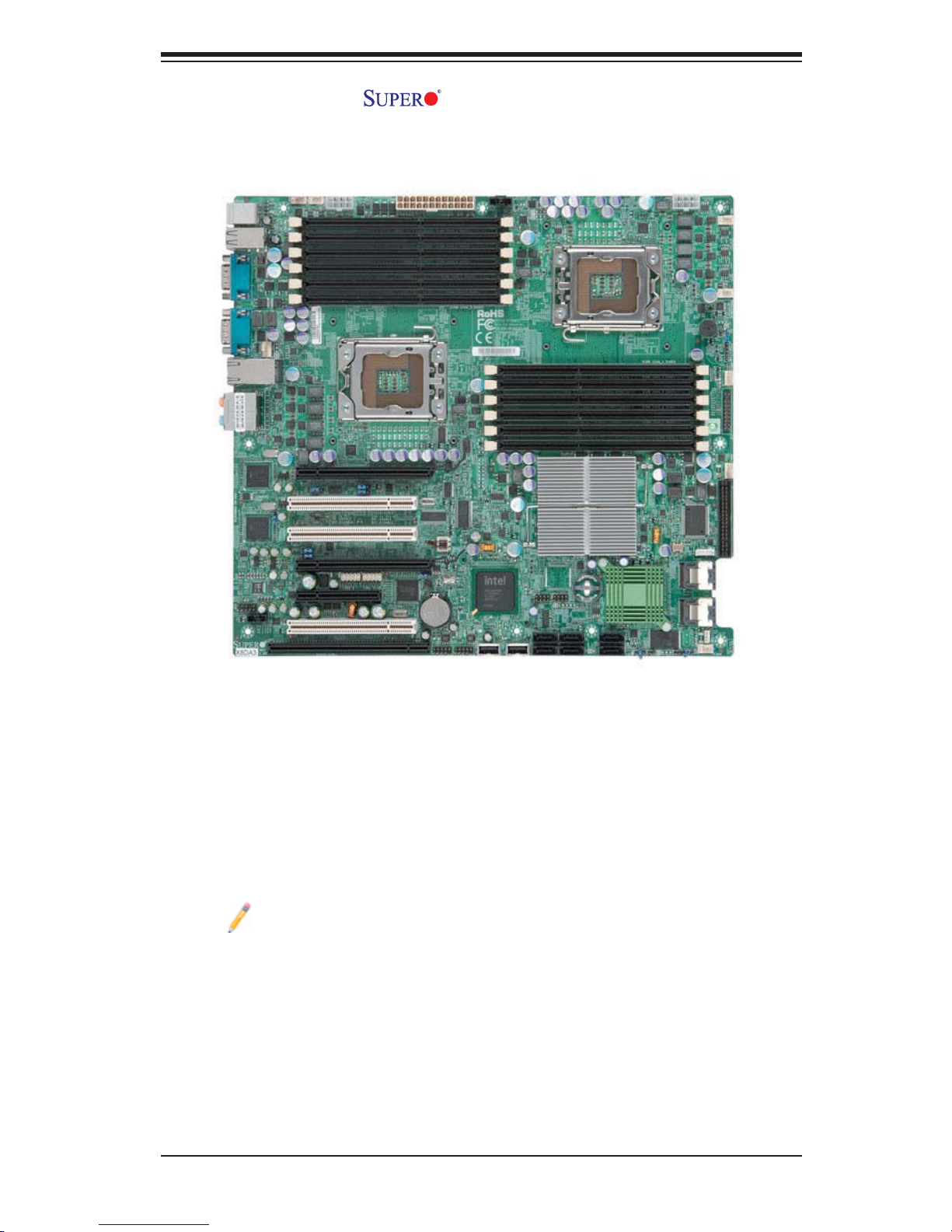
X8DA3/X8DAi Image
Chapter 1: Introduction
Note: The drawings and pictures shown in this manual were based on the
latest PCB Revision available at the time of publishing of the manual. The
motherboard you’ve received may or may not look exactly the same as
the graphics shown in the manual.
1-3
Page 10
X8DA3/X8DAi User's Manual
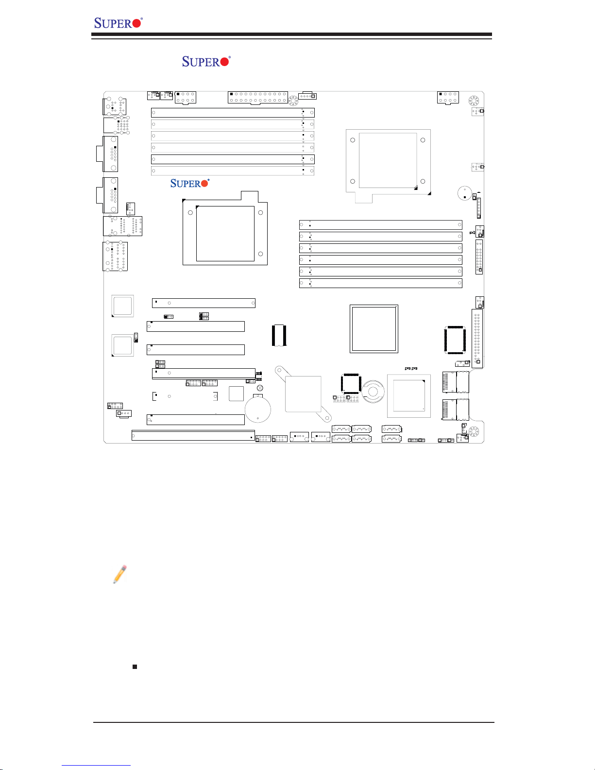
X8DA3/X8DAi Motherboard Layout
0/1
USB
COM1
COM2
LAN1
AUDIO
JC2
82573V
LAN
CTRL
82573L
LAN
CTRL
CD1
KB/Mouse
2/3
USB
Fan8/CPU2 Fan
JPL2
JI2C1
JI2C2
Fan5
LAN2
Fan6
JPL1
JPW2
P2 DIMM1A
P2 DIMM1B
P2 DIMM2A
P2 DIMM2B
P2 DIMM3A
P2 DIMM3B
Slot6 PCI-E x16
1
Slot5 PCI 33MH
Slot4 PCI 33MH
Slot3 PCI-E X16
1394_2
Slot2 PCI-E X4
Slot1 PCI 33MH
Slot0 SIMLC
X8DA3/i
JI2C3
JI2C4
1394_1
CPU2
JPW3
JPF1
Battery
USB6/7
JBT1
JUSB3
SPI BIOS
USB4/5
JUSB2
Super IO
ICH9R
Intel
South
Bridge
USB8
J24
J6
JPW1
Fan1
CPU1
Fan7/CPU1
SP1
JD1
JOH1
P1 DIMM3B
P1 DIMM3A
P1 DIMM2B
P1 DIMM2A
P1 DIMM1B
P1 DIMM1A
LE1
Fan2
JF1
Fan3
Intel IOH
Floppy
USB9
J23
J15
T-SGPIO2
I-SATA5
I-SATA4
T-SGPIO1
I-SATA3
I-SATA2
I-Button
J14
I-SATA1
I-SATA0
LES2
1068E
SAS CTRL
JWD
LES1
JL1
JPS1
JPS2
JSM2
JSM1
J5
SAS 4~7
SAS 0~3
JWOL1
Fan4
Notes:
Jumpers not indicated are for test purposes only.
1.
See Chapter 2 for detailed information on jumpers, I/O ports and JF1 front
2.
panel connections.
" " indicates the location of Pin 1.
3.
When LE1 LED is on, the onboard power connection is on. Make sure to
4.
unplug the power cables before removing or installing components.
1-4
Page 11

Chapter 1: Introduction
X8DA3/X8DAi Quick Reference
Jumper Description Default Setting
JBT1 CMOS Clear (See Section 5-10)
2
JI
C1/JI2C2 SMB to PCI-Express Slots 2-3 (Disabled)
2
JI
C3/JI2C4 SMB to PCI Slots 2-3 (Disabled)
JPF1 1394_1/1394_2 Enable 1-2 (Normal)
JPL1/JPL2 LAN1/2 Enable Pins 1-2 (Enabled)
JPS1 SAS Enable Pins 1-2 (Enabled)
JPS2 SAS RAID Enable Closed (SR RAID Enabled)
JWD Watch Dog Pins 1-2 (Reset)
Connector Description
1394_1/1394_2 1394 Connection Headers
Audio/CD1/JC2 Audio Input_Output_Mic/CD-ROM/HD Audio Headers
COM1/COM2 COM1/COM2 Serial Port/Header
FAN 1-8 System/CPU Fan Headers (Fans 7~8: CPU Fans)
Floppy Floppy Disk Drive Connector
J5 IPMB I
J6 Power Supply SMBbus I
2
C Header (for IPMI Card)
2
C Header
JD1 Speaker Header
JF1 Front Panel Connector
JL1 Chassis Intrusion Header
JOH1 Overheat LED Header
JPW1/JPW2 +12V 8-pin Secondary Power Connector
JPW3 24-pin ATX Main Power Connector
JWOL1 Wake-On-LAN Header
LAN1/2 Gigabit Ethernet (RJ45) Ports
I-SATA0 ~ I-SATA5 (Intel South Bridge) SATA Ports
SIMLC (Low Profi le) SIMLC IPMI 2.0 Socket
T-SGPIO-1/T-SGPIO-2 Serial General Purpose Input/Output Headers
(B/P) USB0/1/2/3 (Back Panel) Universal Serial Bus (USB) Ports
F/P USB 4/5, 6/7, 8, 9 Front Panel Accessible USB Headers
LED Description
LE1 Onboard Standby PWR warning LED Indicator
LES1/LES2 SAS LED Indicators
1-5
Page 12
X8DA3/X8DAi User's Manual
Motherboard Features
CPU
•
Two Intel® Nehalem-EP (LGA 1336) processors, each processor supporting two
full-width Intel QuickPath Interconnect links with a total of up to 51.2 GB/s Data
Transfer Rate (6.4 GB/s per direction)
Memory
Twelve 240-pin DIMM sockets support up to 96 GB of DDR3 Registered ECC
•
Memory (See Section 2-3 in Chapter 2 for DIMM Slot Population.)
Chipset
Intel Tylersburg chipset, including: the Tylersburg Hub (IOH-36D) and the
•
ICH9R.
Expansion Slots
Two PCI-E x16 slot (Slot3 and Slot6)
•
One PCI-E x4 slot (Slot2)
•
Three 32-bit PCI 33 slot (Slot1, Slot4 and Slot5)
•
One SIMLC IPMI Slot (Slot0)
•
BIOS
32 Mb AMI SPI Flash ROM
•
PCI 2.2, ACPI 1.0/2.0/3.0, Plug and Play (PnP), DMI 2.3, RTC (Real Time Clock)
•
Wakeup, USB Keyboard support, and SMBIOS 2.3
PC Health Monitoring
Onboard voltage monitors for CPU cores, chipset voltage, Memory voltage,
•
+3.3V, +3.3V Standby, +5V, +5V Standby, +12V, −12V and Vbatt
Fan status monitor with fi rmware control
•
CPU/chassis temperature monitors
•
Platform Environment Control Interface (PECI) ready
•
Thermal Monitor 2 (TM2) support
•
CPU fan auto-off in sleep mode
•
CPU slow-down on temperature overheat
•
Pulse Width Modulation (PWM) Fan Control
•
CPU thermal trip support for processor protection, power LED
•
Power-up mode control for recovery from AC power loss
•
Auto-switching voltage regulator for CPU cores
•
System overheat/Fan Fail LED Indicator and control
•
Chassis intrusion detection
•
System resource alert via Supero Doctor III
•
1-6
Page 13

Chapter 1: Introduction
ACPI Features
Slow blinking LED for suspend state indicator
•
Main switch override mechanism
•
ACPI Power Management
•
Keyboard Wakeup from Soft-off
•
Onboard I/O
Intel ICH9R supports six SATA2 ports (with RAID0, RAID1, RAID10, RAID5
•
supported in the Windows OS Environment)
LSI 1068E supports eight SAS ports (For X8DA3)
•
One SIMLC IPMI socket
•
Intel 82573V and 82573L Gigabit Ethernet controllers support dual Giga-bit
•
LAN ports
One fl oppy port interface
•
Two COM ports(1 header, 1 port)
•
PS/2 mouse and PS/2 keyboard ports
•
Up to ten USB 2.0 (Universal Serial Bus) (4 Ports, 2 Front Headers, and 2
•
Type A H ea d er s)
Super I/O: Winbond W83627HG
•
High Defi nition 7.1 Audio with Line-in, Line-out and Microphone
•
Two TI 13 94 p or ts
•
Other
External modem ring-on
•
Wake-on-LAN (WOL)
•
Console redirection
•
Onboard Fan Speed Control by Thermal Management via BIOS
•
CD/Diskette Utilities
BIOS fl ash upgrade utility and device drivers
•
Dimensions
Ext. ATX 13.05" (L) x 12.075" (W) (331.47 mm x 306.71 mm)
•
1-7
Page 14
X8DA3/X8DAi User's Manual
DDR3
1333/1066/800
Ports
#0~3
Ports
#4~7
P2DIMM2B
P2DIMM2A
P2DIMM1B
P2DIMM1A
#6
PCI-E X16
SAS
LSI 1068
#1
PCI-E X8
PHY#1
iI82573V
PHY#2
i82573L
1394
TI
PCI-33
PCI-33
PCI-33
SIMLC
P2DIMM3B
P2DIMM3A
PROCESSOR#2
PCI-E x16
#3
PCI-Ex16
PCI-E X16
PCI-Ex4
PCI-Ex4
PCI-Ex1
PCI-Ex1
PCI 33MMZ
#5
#4
#1
#0
QPI
Ports
#3-6
TYLERSBURG
Ports
#7-10
Ports
#1-2
LANES1/2
LANE5
LANE6
MS
KB
QPI
IOH-36D
ICH9
PROCESSOR#1
QPI
Port
#0
ESI
PCIEx4
DMI
R
SIO
W83627
HG
COM1
External
3.0 Gb/S
USB 2.0
LPC
COM2
External/SOL
SPI
TPM
#0
#0
#1
#1
DDR3
#2
#2
P1DIMM3B
P1DIMM3A
1333/1066/800
AC'97
#5
#4
#3
SATA
#5
#3
USB
P1DIMM1B
P1DIMM1A
P1DIMM2B
P1DIMM2A
4 Rear
4 Front
2 Type-A
#9
#8
#7
#6
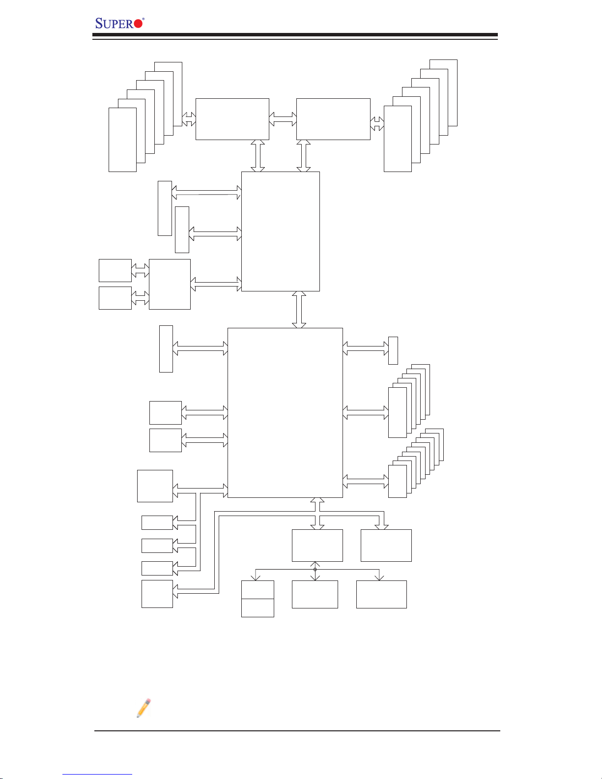
Block Diagram of the Tylersburg-EP Platform
Note: This is a general block diagram. Please see the previous Mother-
board Features pages for details on the features of each motherboard.
1-8
Page 15

Chapter 1: Introduction
1-3 Chipset Overview
Built upon the functionality and the capability of the Tylersburg-EP platform, the
X8DA3/X8DAi motherboard provides the performance and feature set required for
dual-processor-based high-end systems with confi guration options optimized for
workstations, high-end CAD systems, and intensive applications. The Tylersburg-
EP platform consists of the Nehalem-EP (LGA 1336) processor, the Tylersburg
IOH (IOH-D36), and the South Bridge (ICH9R). With the Intel QuickPath intercon-
nect controller built in the processor, the Tylersburg-EP platform is the fi rst dual-
processing platform to offer the next generation point-to-point system interconnect
interface, replacing the current Front Side Bus Technology, providing substantial
system performance enhancement by utilizing serial link interconnections, allowing
for increased bandwidth and scalability.
The IOH connects to each processor through an independent QuickPath Inter-
connect link. Each link consists of 20 pairs of unidirectional differential lanes for
transmission and receiving in addition to a differential forwarded clock. A full-width
QuickPath interconnect link pair provides 84 signals. Each processor supports two
QuickPath link, one going to the other processor and the other to the Tylersburg
IOH-36D.
The Tylersburg IOH-36D supports up to 36 PCI Express Gen2 lanes, and the
IOH-36D supports peer-to-peer read and write transactions. The ICH9R provides
up to 6 PCI-Express ports, six SATA ports and 10 USB connections.
In addition, the Tylersburg- EP platform also of fers a wide range of RAS (Reliabilit y,
Availability and Serviceability) features. These features include memory interface
ECC, x4/x8 Single Device Data Correction (SDDC), Cyclic Redundancy Check
(CRC), parity protection, out-of-band register access via SMBus, memory mirror-
ing, memory sparing, and Hot-plug support on the PCI-Express Interface.
Nehalem-EP Processor and Tylersburg IOH Features
Four processor cores in each processor with 8MB shared cache among cores
•
Two full-width Intel QuickPath interconnect links, up to 6.4 GT/s of data transfer
•
rate in each direction
Virtualization Technology, Integrated Management Engine supported
•
Point-to-point cache coherent interconnect, Fast/narrow unidirectional links, and
•
Concurrent bi-directional traffi c
Error detection via CRC and Error correction via Link level retry
•
1-9
Page 16
X8DA3/X8DAi User's Manual
1-4 Special Features
Recovery from AC Power Loss
BIOS provides a setting for you to determine how the system will respond when
AC power is lost and then restored to the system. You can choose for the system
to remain powered off (in which case you must hit the power switch to turn it back
on) or for it to automatically return to a power- on state. See the Advanced BIOS
Setup section to change this setting. The default setting is Last State.
1-5 PC Health Monitoring
This section describes the PC health monitoring features of the X8DA3/X8DAi. All
have an onboard System Hardware Monitor chip that supports PC health monitoring.
An onboard voltage monitor will scan these onboard voltages continuously: CPU
Core, Chipset Voltage, Memory Voltage, +5V, +3.3V, +3.3V Standby, +5V Standby,
+12V, −12V and VBatt. Once a voltage becomes unstable, a warning is given or
an error message is sent to the screen. Users can adjust the voltage thresholds
to defi ne the sensitivity of the voltage monitor.
Fan Status Monitor with Firmware Control
The PC health monitor can check the RPM status of the cooling fans. The onboard
CPU and chassis fans are controlled by Thermal Management via BIOS (under
Hardware Monitoring in the Advanced Setting).
Environmental Temperature Control
The thermal control sensor monitors the CPU temperature in real time and will turn
on the thermal control fan whenever the CPU temperature exceeds a user-defi ned
threshold. The overheat circuitry runs independently from the CPU. Once it detects
that the CPU temperature is too high, it will automatically turn on the thermal fan
control to prevent any overheat damage to the CPU. The onboard chassis thermal
circuitry can monitor the overall system temperature and alert users when the chas-
sis temperature is too high.
CPU Fan Auto-Off in Sleep Mode
The CPU fan becomes active when the power is turned on. It continues to operate
when the system enters the Standby mode. When in the sleep mode, the CPU will
not run at full power, thereby generating less heat.
1-10
Page 17

Chapter 1: Introduction
CPU Overheat LED and Control
This feature is available when the user enables the CPU overheat warning func-
tion in the BIOS. This allows the user to defi ne an overheat temperature. When
the CPU temperature passes this threshold, both the overheat fan and the warning
LED are triggered.
System Resource Alert
This feature is available when used with Supero Doctor III in the Windows OS
environment or used with Supero Doctor II in Linux. Supero Doctor is used to
notify the user of certain system events. For example, you can also confi gure
Supero Doctor to provide you with warnings when the system temperature, CPU
temperatures, voltages and fan speeds go beyond a pre-defi ned range.
1-6 ACPI Features
ACPI stands for Advanced Confi guration and Power Interface. The ACPI specifi ca-
tion defi nes a fl exible and abstract hardware interface that provides a standard
way to integrate power management features throughout a PC system, including
its hardware, operating system and application software. This enables the system
to automatically turn on and off peripherals such as CD-ROMs, network cards, hard
disk drives and printers.
In addition to enabling operating system-directed power management, ACPI
provides a generic system event mechanism for Plug and Play and an operating
system-independent interface for confi guration control. ACPI leverages the Plug
and Play BIOS data structures while providing a processor architecture-independent
implementation that is compatible with both Windows 2000 and Windows 2003
Operating Systems.
Slow Blinking LED for Suspend-State Indicator
When the CPU goes into a suspend state, the chassis power LED will start blinking
to indicate that the CPU is in suspend mode. When the user presses any key, the
CPU will wake-up and the LED will automatically stop blinking and remain on.
Main Switch Override Mechanism
When an ATX power supply is used, the power button can function as a system
suspend button to make the system enter a SoftOff state. The monitor will be
suspended and the hard drive will spin down. Pressing the power button again
will cause the whole system to wake-up. During the SoftOff state, the ATX power
supply provides power to keep the required circuitry in the system "alive." In case
1-11
Page 18
X8DA3/X8DAi User's Manual
the system malfunctions and you want to turn off the power, just press and hold
the power button for 4 seconds. This option can be set in the Power section of
the BIOS Setup routine.
Wake-On-LAN (WOL)
Wake-On-LAN is defi ned as the ability of a management application to remotely
power up a computer that is powered off. Remote PC setup, up-dates and asset
tracking can occur after hours and on weekends so that daily LAN traffi c is kept to
a minimum and users are not interrupted. The motherboard has a 3-pin header
(WOL) to connect to the 3-pin header on a Network Interface Card (NIC) that has
WOL capability. In addition, an onboard LAN controller can also support WOL
without any connection to the WOL header. The 3-pin WOL header is to be used
with a LAN add-on card only.
Note: Wake-On-LAN requires an ATX 2.01 (or above) compliant power
supply.
1-7 Power Supply
As with all computer products, a stable power source is necessary for proper and
reliable operation. It is even more important for processors that have high CPU
clock rates.
The X8DA3/X8DAi can accommodate 24-pin ATX power supplies. Although most
power supplies generally meet the specifi cations required by the CPU, some are
inadequate. In addition, the 12V 8-pin power connections are also required to ensure
adequate power supply to the system. Also your power supply must supply 1.5A
for the Ethernet ports.
Note: The + 12V 8-pin CPU Power Connector (JPW2) is also required to
support Intel 64-bit CPUs. Failure to provide this extra power will result in
CPU PWR Failure. See Section 2-5 for details on connecting the power
supply.
It is strongly recommended that you use a high quality power supply that meets ATX
power supply Specifi cation 2.02 or above. It must also be SSI compliant (For more
information, please refer to the web site at http://www.ssiforum.org/). Additionally, in
areas where noisy power transmission is present, you may choose to install a line
fi lter to shield the computer from noise. It is recommended that you also install a
power surge protector to help avoid problems caused by power surges.
1-12
Page 19

Chapter 1: Introduction
1-8 Super I/O
The disk drive adapter functions of the Super I/O chip include a fl oppy disk drive
controller that is compatible with industry standard 82077/765, a data separator,
write pre-compensation circuitry, decode logic, data rate selection, a clock genera-
tor, drive interface control logic and interrupt and DMA logic. The wide range of
functions integrated onto the Super I/O greatly reduces the number of components
required for interfacing with fl oppy disk drives. The Super I/O supports 360 K, 720
K, 1.2 M, 1.44 M or 2.88 M disk drives and data transfer rates of 250 Kb/s, 500 Kb/s
or 1 Mb/s. It also provides two high-speed, 16550 compatible serial communication
ports (UARTs). Each UART includes a 16-byte send/receive FIFO, a programmable
baud rate generator, complete modem control capability and a processor interrupt
system. Both UARTs provide legacy speed with baud rate of up to 115.2 Kbps
as well as an advanced speed with baud rates of 250 K, 500 K, or 1 Mb/s, which
support higher speed modems.
The Super I/O provides functions that comply with ACPI (Advanced Confi guration
and Power Interface), which includes support of legacy and ACPI power manage-
ment through an SMI or SCI function pin. It also features auto power management
to reduce power consumption.
1-13
Page 20
X8DA3/X8DAi User's Manual
Notes
1-14
Page 21

Chapter 2: Installation
Chapter 2
Installation
2-1 Static-Sensitive Devices
Electrostatic Discharge (ESD) can damage electronic com ponents. To prevent dam-
age to your system board, it is important to handle it very carefully. The following
measures are generally suffi cient to protect your equipment from ESD.
Precautions
Use a grounded wrist strap designed to prevent static discharge.
•
Touch a grounded metal object before removing the board from the antistatic
•
bag.
Handle the board by its edges only; do not touch its components, peripheral
•
chips, memory modules or gold contacts.
When handling chips or modules, avoid touching their pins.
•
Put the motherboard and peripherals back into their antistatic bags when not
•
in use.
For grounding purposes, make sure your computer chassis provides excellent
•
conductivity between the power supply, the case, the mounting fasteners and
the motherboard.
Use only the correct type of onboard CMOS battery as specifi ed by the
•
manufacturer. Do not install the onboard battery upside down to avoid possible
explosion.
Unpacking
The motherboard is shipped in antistatic packaging to avoid static damage. When
unpacking the board, make sure the person handling it is static protected.
2-1
Page 22
X8DA3/X8DAi User's Manual
!
2-2 Processor and Heatsink Installation
When handling the processor package, avoid placing direct pressure on
the label area of the fan.
Notes:
1.
Always connect the power cord last and always remove it before adding, re-
moving or changing any hardware components. Make sure that you install the
processor into the CPU socket before you install the CPU heatsink.
2.
Intel's boxed Xeon CPU package contains the CPU fan and heatsink assem-
bly. If you buy a CPU separately, make sure that you use only Intel-certifi ed
multi-directional heatsink and fan.
3.
Make sure to install the motherboard into the chassis before you install the
CPU heatsink and fan.)
4.
When purchasing a Nehalem-EP processor or when receiving a motherboard
with a Nehalem-EP processor pre-installed, make sure that the CPU plastic
cap is in place, and none of the CPU pins are bent; otherwise, contact the
retailer immediately.
5.
Refer to the MB Features Section for more details on CPU support.
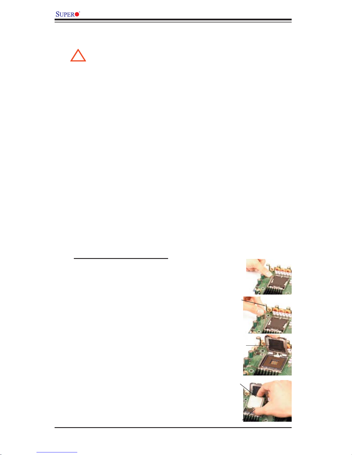
Installing an LGA Processor
Press the socket clip to release the
1.
load plate, which covers the CPU
socket, from its locking position.
Socket Clip
Gently lift the socket clip to open the
2.
load plate.
Use your thumb and your index fi nger
3.
to hold the CPU at the North Center
Edge and the South Center Edge of
the CPU.
Load Plate
North Center Edge
South Center Edge
2-2
Page 23
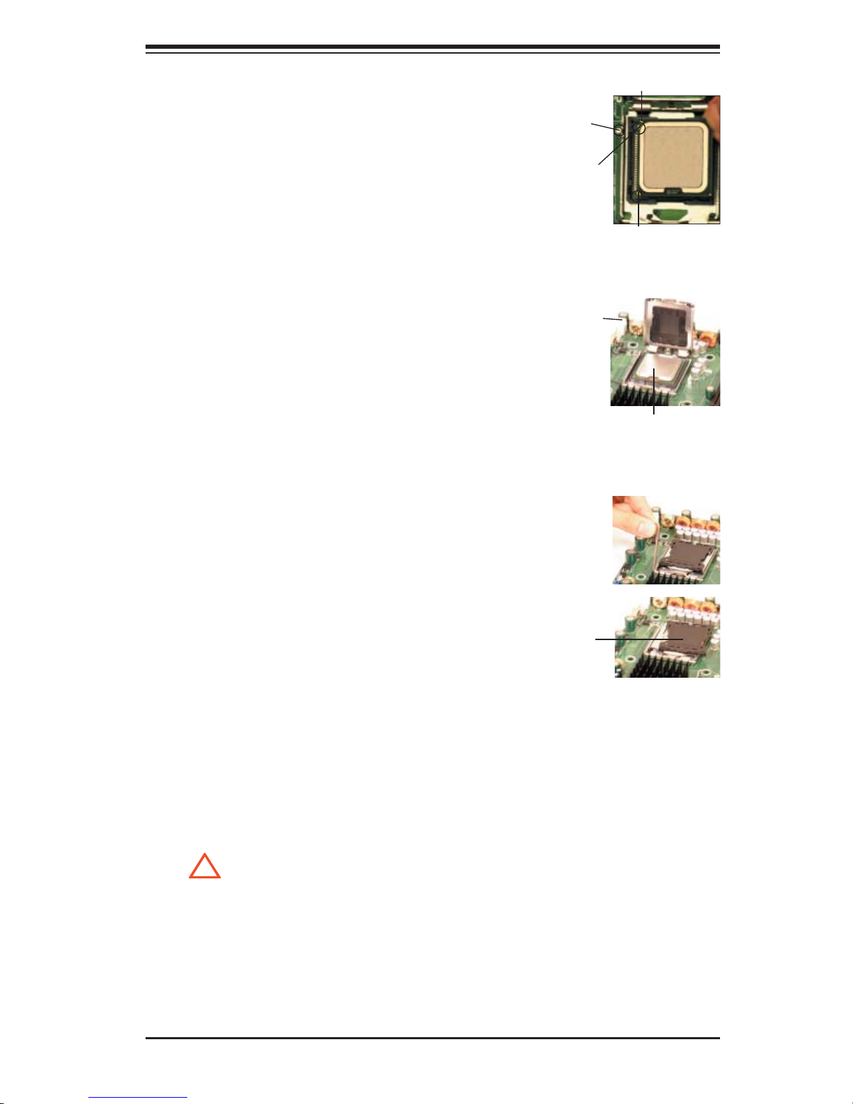
Align CPU Pin1 (the CPU corner
!
4.
marked with a triangle) against the
socket corner marked with a triangle
cutout.
Align the CPU key, the semi-circle
5.
cutout below a gold dot, against the
socket key, which is the notch on
the same side of the triangle cutout
on the socket.
Chapter 2: Installation
gold dot
Socket Key
(Socket Notch)
CPU Key (semi-
circle cutout)
below the circle.
Pin 1 w/a Tri-
angle Corner
Once aligned, carefully lower the
6.
CPU straight down into the socket.
(Do not drop the CPU on the
socket. Do not move the CPU hori-
zontally or vertically. Do not rub the
CPU against the surface or against
any pins of the socket to avoid dam-
aging the CPU or the socket.)
With the CPU inside the socket, in-
7.
spect the four corners of the CPU to
make sure that the CPU is properly
installed.
Use your thumb to gently push the
8.
socket clip down to the clip lock.
If the CPU is properly installed into
9.
the socket, the plastic cap will be
automatically released from the load
plate when the clip is pushed in the
clip lock. Remove the plastic cap
from the motherboard.
Socket clip
CPU in the CPU socket
Plastic cap
is released
from the
load plate
if the CPU
is properly
installed.
Warning: Please save the plas-
tic cap. The motherboard must
be shipped with the plastic cap
properly installed to protect the
CPU socket pins. Shipment
without the plastic cap properly
installed will cause damage to
the socket pins.
2-3
Page 24
X8DA3/X8DAi User's Manual
!
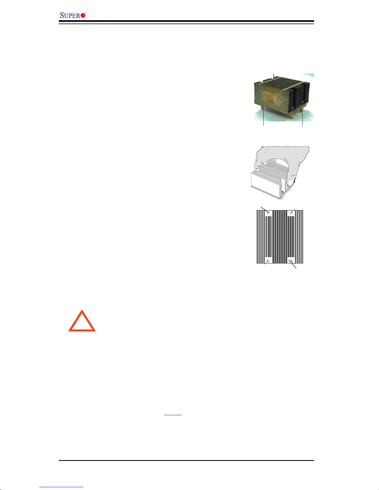
Installing a CEK Heatsink
Do not apply any thermal grease to
1.
the heatsink or the CPU die because
the required amount has already been
applied.
Place the heatsink on top of the CPU
2.
so that the four mounting holes are
aligned with those on the retention
mechanism.
3. Screw in two diagonal screws (ie the
#1 and the #2 screws) until just snug
(-do not fully tighten the screws to avoid
possible damage to the CPU.)
4. Finish the installation by fully tightening
all four screws.
CEK Passive Heatsink
Screw#1 Screw#2
Screw#1
Un-installing the Heatsink
Warning: We do not recommend that the CPU or the heatsink be re-
moved. However, if you do need to uninstall the heatsink, please follow
the instructions below to uninstall the heatsink to prevent damage done
to the CPU or the CPU socket.
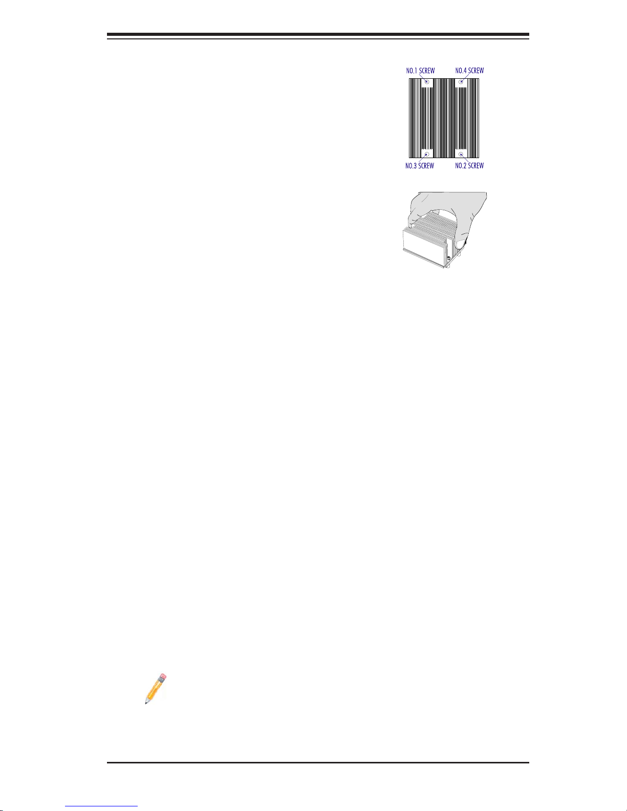
Unscrew and remove the
1.
heatsink screws from the mother-
board in the sequence as show in
the picture on the right.
Hold the heatsink as shown in
2.
the picture on the right and gently
wriggle the heatsink to loosen
it from the CPU. (Do not use
excessive force when wriggling
the heatsink.)
Screw#2
2-4
Page 25
Chapter 2: Installation
3. Once the CPU is loosened, remove
the heatsink from the CPU socket.
4. Clean the surface of the CPU and the
heatsink to get rid of the old thermal
grease. Reapply the proper amount
of thermal grease on the surface
before you re-install the CPU and the
heatsink.
Screw#1
Screw#2
Mounting the Motherboard in the Chassis
All motherboards have standard mounting holes to fi t different types of chassis.
Make sure that the locations of all the mounting holes for both motherboard and
chassis match. Make sure that the metal standoffs click in or are screwed in tightly.
Then, use a screwdriver to secure the motherboard onto the motherboard tray.
Note: some components are very close to the mounting holes. Please take
precautionary measures to avoid damaging these components when you
install the motherboard to the chassis.
2-5
Page 26
X8DA3/X8DAi User's Manual
2-3 Memory Installation
Note: Check the Supermicro web site for recommended memory modules.
CAUTION
Exercise extreme care when installing or removing DIMM
modules to prevent any possible damage. Also note that the
memory is interleaved to improve performance (See step 1).
DIMM Installation
Insert the desired number of DIMMs into the memory slots, starting with
1.
DIMM #1A. When populating two DIMM modules within a channel, always
start with Bank1 fi rst. For optimal memory performance, please install a pair
(or pairs) of memory modules of the same type and same speed at a time
with the maximum of 12 modules. (See the Memory Installation Table Below.)
Insert each DIMM module vertically into its slot. Pay attention to the notch
2.
along the bottom of the module to prevent inserting the DIMM module incor-
rectly.
Gently press down on the DIMM module until it snaps into place in the slot.
3.
Repeat for all modules.
2-6
Page 27
Chapter 2: Installation
Memory Support
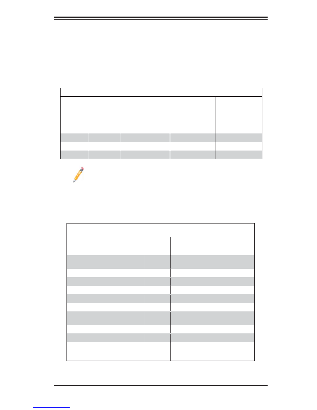
The X8DA3/X8DAi supports up to 96 GB Registered ECC DDR3 1333 MHz/1066
MHz/800 MHz in 12 DIMMs.
DIMM Module Population Confi guration
For memory to work properly, follow the tables below for memory installation:
DIMM Population Table
DIMM
Slots per
Channel
2 1 Reg. DDR3 ECC 800,1066,1333 SR, DR
2 1 Reg. DDR3 ECC 800,1066, QR
2 2 Reg. DDR3 ECC 800,1066,1333 SR, DR
2 2 Reg. DDR3 ECC 800,1066 SR, DR, QR
DIMMs
Populated
per Channel
DIMM Type (Reg.=
Registered)
Speeds (in MHz) Ranks per DIMM
(any combination;
SR=Single Rank,
DR=Dual Rank,
QR=Quad Rank)
Note 1: Due to OS limitations, some operating systems may not show
more than 4 GB of memory.
Note 2: Due to memory allocation to system devices, the amount of
memory that remains available for operational use will be reduced when
4 GB of RAM is used. The reduction in memory availability is dispropor-
tional. (See the following Memory Availability Table.)
Possible System Memory Allocation & Availability
System Device Size Physical Memory
Firmware Hub fl ash memory (System
BIOS)
Local APIC 4 KB 3.99 GB
Area Reserved for the chipset 2 MB 3.99 GB
I/O APIC (4 Kbytes) 4 KB 3.99 GB
PCI Enumeration Area 1 256 MB 3.76 GB
PCI Express (256 MB) 256 MB 3.51 GB
PCI Enumeration Area 2 (if needed)
-Aligned on 256-MB boundary-
VGA Memory 16 MB 2.85 GB
TSEG 1 MB 2.84 GB
Memory available for the OS & other
applications
1 MB 3.99 GB
512 MB 3.01 GB
Remaining (-Available) (4 GB Total System
Memory)
2.84 GB
2-7
Page 28
X8DA3/X8DAi User's Manual
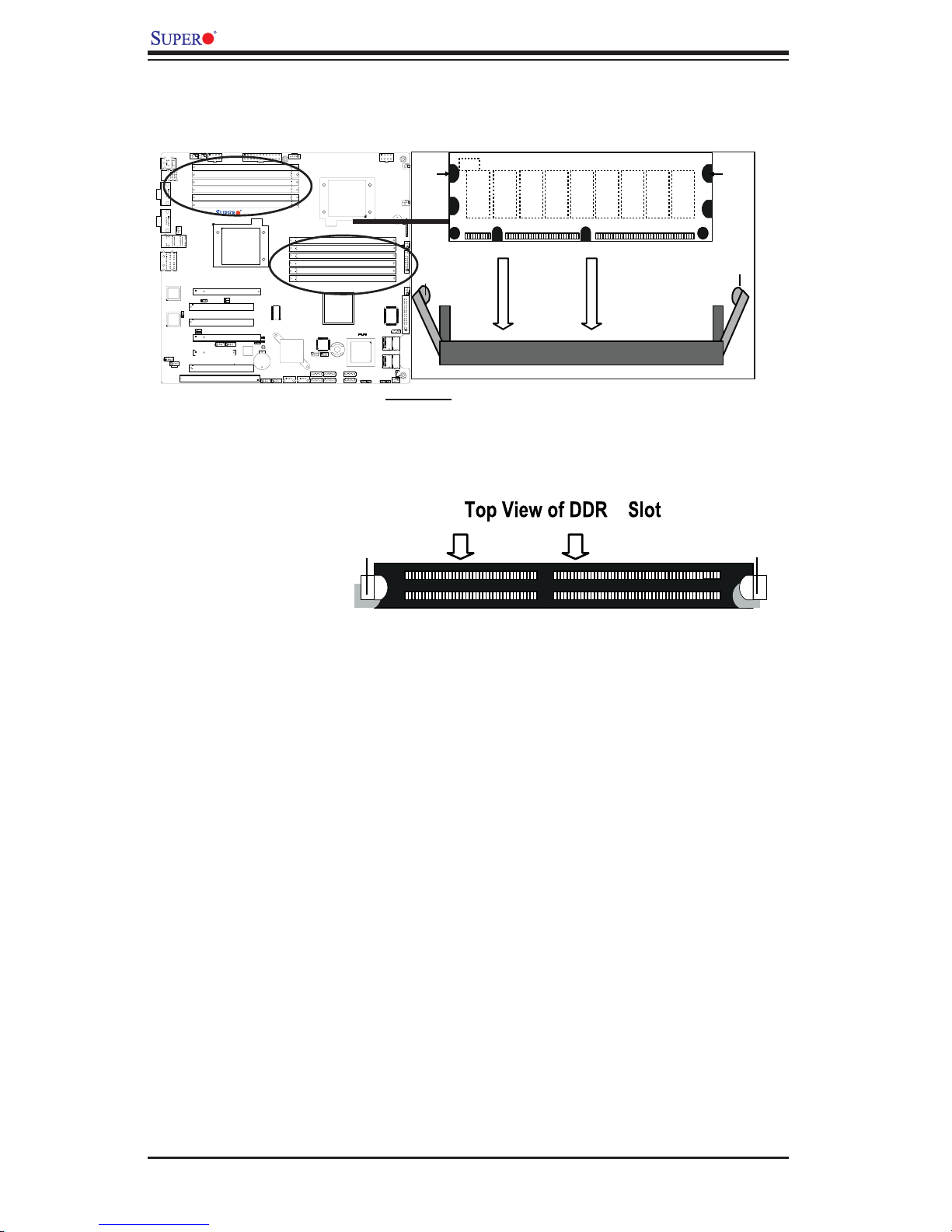
Installing and Removing DIMMs
X8DA3/i
To Remove:
Use your thumbs
to gently push
the release tabs
near both ends of
the module. This
should release it
from the slot.
Notch
Release
Tab
DIMM DDR3
Note: Notch
should align
with the
receptive point
on the slot
To I n s t a l l : Insert module vertically and press down until it
snaps into place. Pay attention to the alignment notch at
the bottom.
3
Release Tab
Notch
Release
Tab
Release Tab
2-8
Page 29
Chapter 2: Installation
1
2
3
4
5
6
7
8
9
2-4 Control Panel Connectors/IO Ports
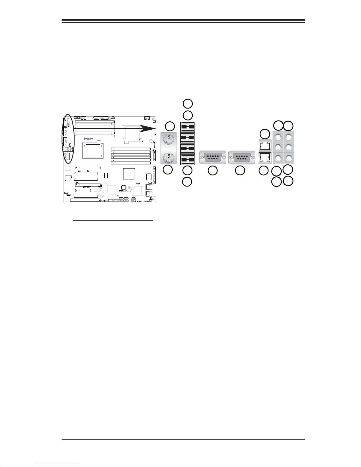
The I/O ports are color coded in conformance with the PC 99 specifi cation. See
the picture below for the colors and locations of the various I/O ports.
1. Back Panel Connectors/IO Ports
13
X8DA3/i
10
12
11
16
15
14
Back Panel I/O Port Locations and Defi nitions
Back Panel Connectors
Keyboard (Purple)
1.
PS/2 Mouse (Green)
2.
Back Panel USB Port 0
3.
Back Panel USB Port 1
4.
Back Panel USB Port 2
5.
Back Panel USB Port 3
6.
COM Port 1 (Turquoise)
7.
COM Port 1 (Turquoise)
8.
Gigabit LAN 1
9.
Gigabit LAN 2
10.
Side_Surround (Grey)
11.
Back_Surround (Black)
12.
CEN/LFE (Orange)
13.
Microphone-In (Pink)
14.
Front (Green)
15.
Line-In (Blue)
16.
(See Section 2-5 for details.)
2-9
Page 30
X8DA3/X8DAi User's Manual
2. Front Control Panel
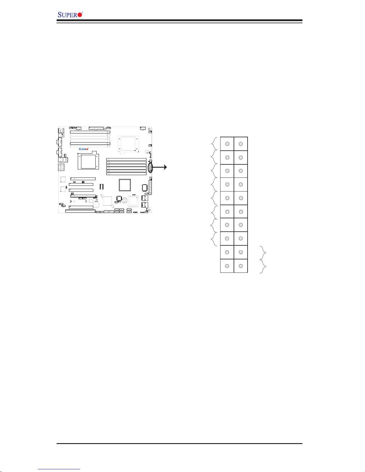
JF1 contains header pins for various buttons and indicators that are normally lo-
cated on a control panel at the front of the chassis. These connectors are designed
specifi cally for use with Supermicro server chassis. See the fi gure below for the
descriptions of the various control panel buttons and LED indicators. Refer to the
following section for descriptions and pin defi nitions.
JF1 Header Pins
1920
X8DA3/i
Ground
X
NMI
X
Power LED
HDD LED
NIC1 LED
NIC2 LED
OH/Fan Fail LED
PWR Fail LED
Ground
Ground
Vcc
Vcc
Vcc
Vcc
Vcc
Vcc
Reset
PWR
2
1
Reset Button
Power Button
2-10
Page 31
3. Front Control Panel Pin Defi nitions
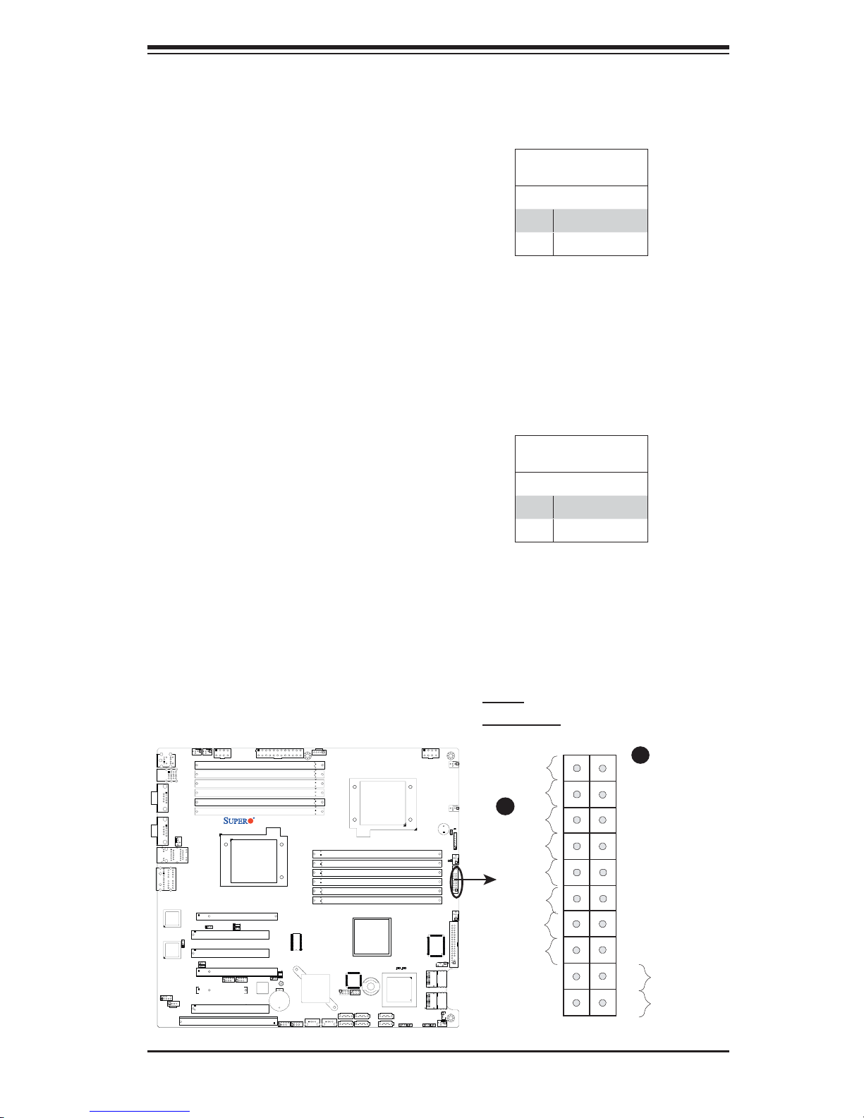
NMI Button
Chapter 2: Installation
The non-maskable interrupt button
header is located on pins 19 and 20
of JF1. Refer to the table on the right
for pin defi nitions.
Power LED
The Power LED connection is located
on pins 15 and 16 of JF1. Refer to the
table on the right for pin defi nitions.
NMI Button
Pin Defi nitions (JF1)
Pin# Defi nition
19 Control
20 Ground
Power LED
Pin Defi nitions (JF1)
Pin# Defi nition
15 +5V
16 Ground
X8DA3/i
2-11
A. NMI
B. PWR LED
Ground
X
B
Power LED
HDD LED
NIC1 LED
NIC2 LED
OH/Fan Fail LED
PWR Fail LED
Ground
Ground
1920
A
NMI
X
Vcc
Vcc
Vcc
Vcc
Vcc
Vcc
Reset
Reset Button
Power Button
PWR
2
1
Page 32
X8DA3/X8DAi User's Manual
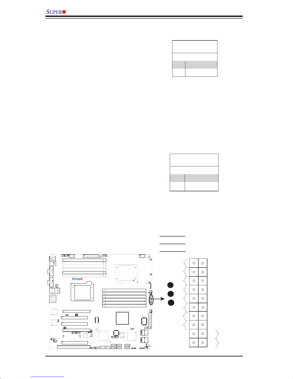
HDD LED
The HDD LED connection is located
on pins 13 and 14 of JF1. Attach a
hard drive LED cable here to display
disk activity (for any hard drive ac-
tivities on the system, including SAS,
Serial ATA and IDE). See the table on
the right for pin defi nitions.
NIC1/NIC2 LED Indicators
The NIC (Network Interface Control-
ler) LED connection for GLAN port 1 is
located on pins 11 and 12 of JF1, and
the LED connection for GLAN Port 2
is on Pins 9 and 10. Attach the NIC
LED cables to display network activity.
Refer to the table on the right for pin
defi nitions.
HDD LED
Pin Defi nitions (JF1)
Pin# Defi nition
13 +5V
14 HD Active
GLAN1/2 LED
Pin Defi nitions (JF1)
Pin# Defi nition
9/11 Vcc
10/12 Ground
X8DA3/i
2-12
A. HDD LED
B. NIC1 LED
C. NIC2 LED
Ground
X
Power LED
A
HDD LED
B
NIC1 LED
C
NIC2 LED
OH/Fan Fail LED
PWR Fail LED
Ground
Ground
1920
NMI
X
Vcc
Vcc
Vcc
Vcc
Vcc
Vcc
Reset
Reset Button
Power Button
PWR
2
1
Page 33
Chapter 2: Installation
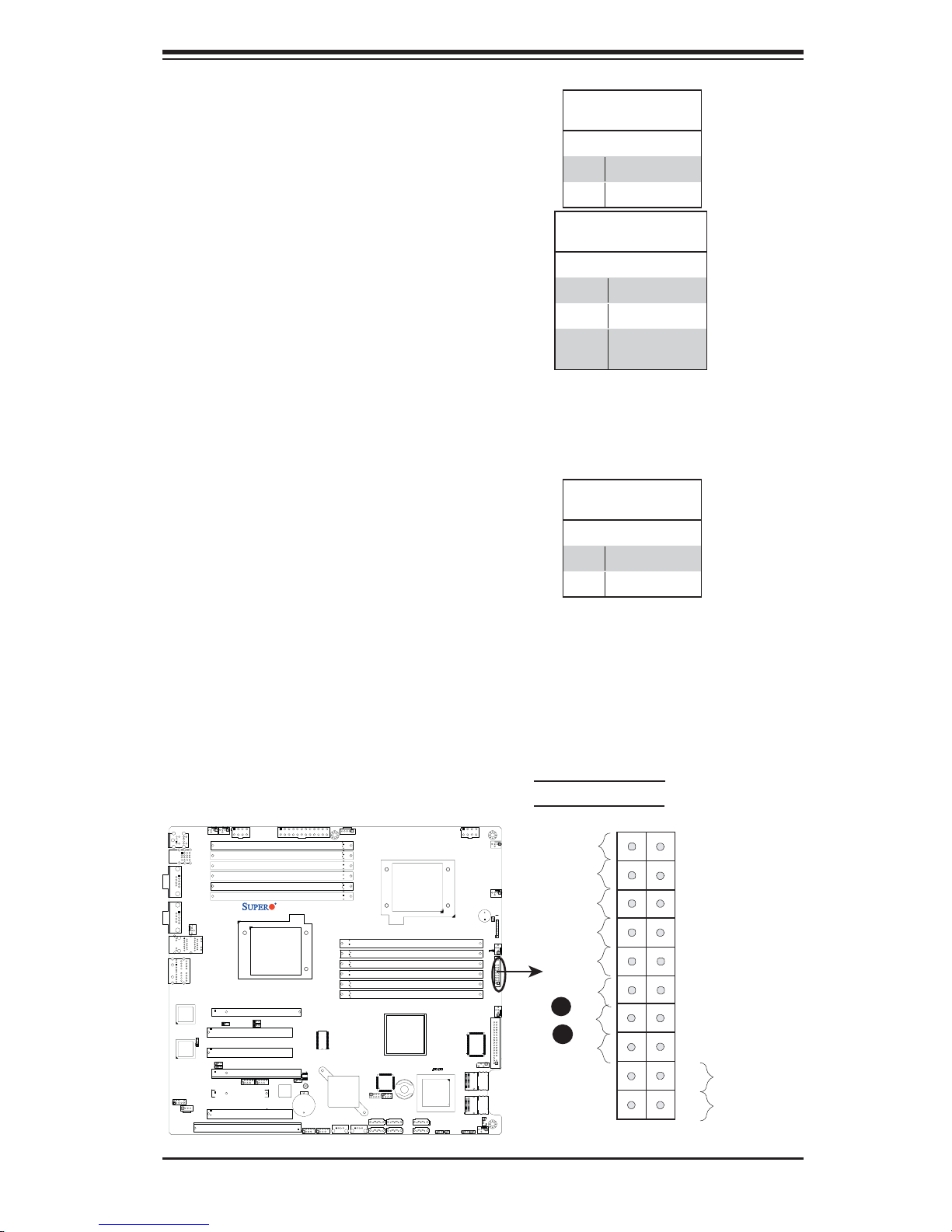
Overheat (OH)/Fan Fail LED
Connect an LED Cable to the OH/Fan
Fail connection on pins 7 and 8 of
JF1 to provide advanced warnings
of chassis overheating or fan failure.
Refer to the table on the right for pin
defi nitions.
Power Fail LED
The Power Fail LED connection is
located on pins 5 and 6 of JF1. Re-
fer to the table on the right for pin
defi nitions.
OH/Fan Fail LED
Pin Defi nitions (JF1)
Pin# Defi nition
7 Vcc
8 Ground
OH/Fan Fail Indicator
Status
State Defi nition
Off Normal
On Overheat
Flashing
Fan Fail
PWR Fail LED
Pin Defi nitions (JF1)
Pin# Defi nition
5 Vcc
6 Ground
X8DA3/i
2-13
A. OH/Fan Fail LED
B. PWR Supply Fail
Ground
X
Power LED
HDD LED
NIC1 LED
NIC2 LED
OH/Fan Fail LED
A
B
PWR Fail LED
Ground
Ground
1920
NMI
X
Vcc
Vcc
Vcc
Vcc
Vcc
Vcc
Reset
Reset Button
Power Button
PWR
2
1
Page 34
X8DA3/X8DAi User's Manual
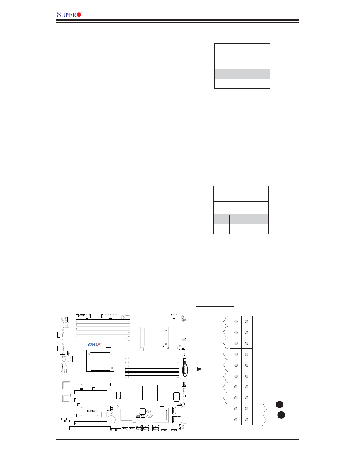
Reset Button
The Reset Button connection is located
on pins 3 and 4 of JF1. Attach it to a
hardware reset switch on the computer
case. Refer to the table on the right for
pin defi nitions.
Power Button
The Power Button connection is located
on pins 1 and 2 of JF1. Momentarily con-
tacting both pins will power on/off the sys-
tem. This button can also be confi gured
to function as a suspend button (with a
setting in the BIOS - see Chapter 4). To
turn off the power when set to suspend
mode, press the button for at least 4
seconds. Refer to the table on the right
for pin defi nitions.
Reset Button
Pin Defi nitions (JF1)
Pin# Defi nition
3 Reset
4 Ground
Power Button
Pin Defi nitions (JF1)
Pin# Defi nition
1 Signal
2 +3V Standby
X8DA3/i
2-14
A. Reset Button
B. PWR Button
Ground
X
Power LED
HDD LED
NIC1 LED
NIC2 LED
OH/Fan Fail LED
PWR Fail LED
Ground
Ground
1920
NMI
X
Vcc
Vcc
Vcc
Vcc
Vcc
Vcc
Reset
PWR
2
1
A
Reset Button
B
Power Button
Page 35
Chapter 2: Installation
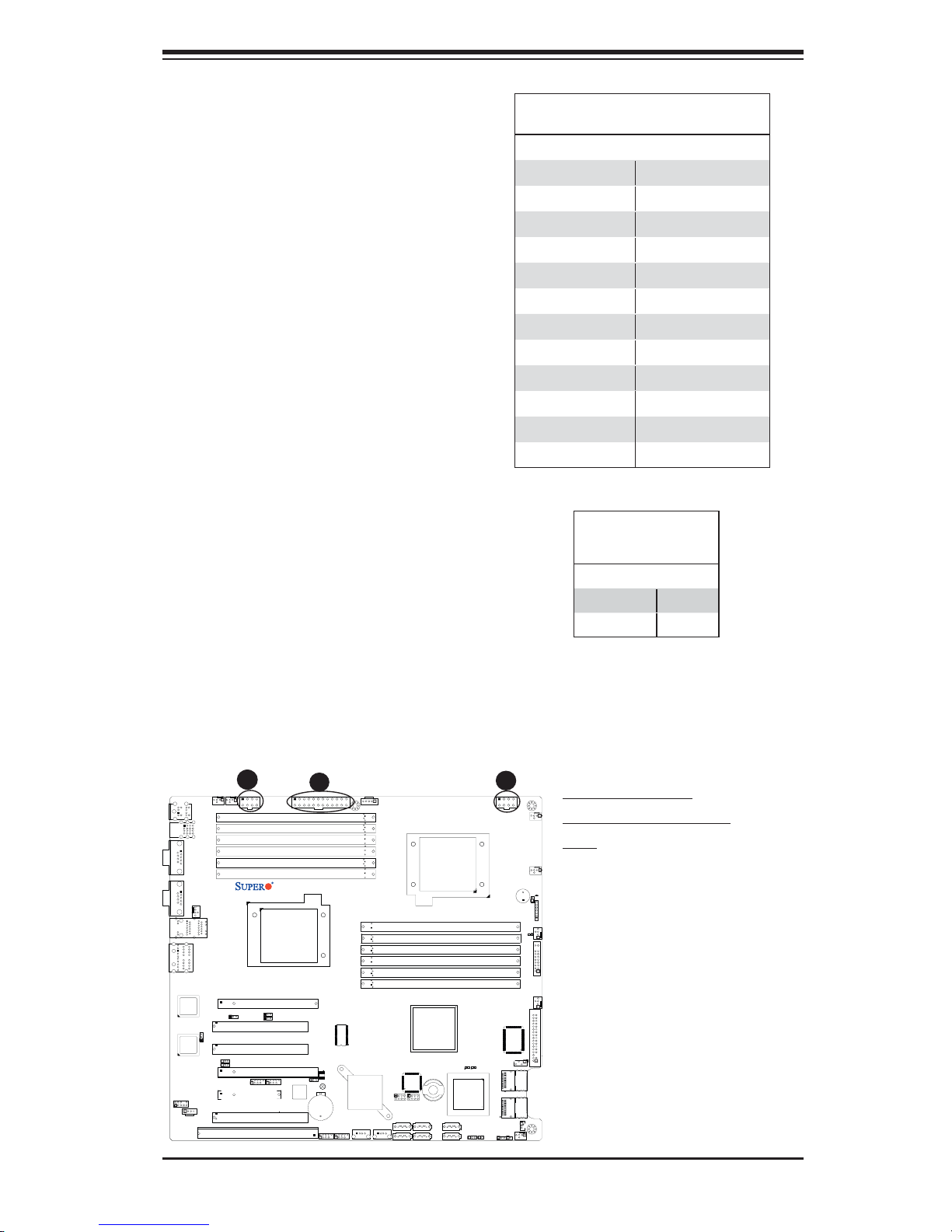
2-5 Connecting Cables
ATX Power Connector
There are a 24-pin main power sup-
ply connector(JPW3) and two 8-pin
CPU PWR connectors (JPW1/JPW2)
on the motherboard. These power
connectors meet the SSI EPS 12V
specification. For the 8-pin PWR
(JPW1/JPW2), please refer to the
item listed below.
Processor Power Connector
In addition to the Primary ATX power
connector, the 12V 8-pin CPU PWR
connectors at JPW1/JPW2 must also
be connected to your power supply.
See the table on the right for pin
defi nitions.
ATX Power 24-pin Connector
Pin Defi nitions
Pin# Defi nition Pin # Defi nition
13 +3.3V 1 +3.3V
14 -12V 2 +3.3V
15 COM 3 COM
16 PS_ON 4 +5V
17 COM 5 COM
18 COM 6 +5V
19 COM 7 COM
20 Res (NC) 8 PWR_OK
21 +5V 9 5VSB
22 +5V 10 +12V
23 +5V 11 +12V
24 COM 12 +3.3V
12V 8-pin Power Con-
nector
Pin Defi nitions
Pins Defi nition
1 through 4 Ground
5 through 8 +12V
0/1
COM1
COM2
LAN1
AUDIO
C
Fan5
Fan6
2/3
USB
Fan8/CPU2 Fan
LAN2
JPL2
JI2C1
JI2C2
JPL1
JPW2
P2 DIMM1A
P2 DIMM1B
P2 DIMM2A
P2 DIMM2B
P2 DIMM3A
P2 DIMM3B
Slot6 PCI-E x16
Slot5 PCI 33MH
Slot4 PCI 33MH
Slot3 PCI-E X16
1394_2
Slot2 PCI-E X4
Slot1 PCI 33MH
Slot0 SIMLC
1
1394_1
KB/Mouse
USB
82573V
LAN
CTRL
82573L
LAN
CTRL
JC2
CD1
X8DA3/i
CPU2
JI2C3
JI2C4
A
JPW3
JPF1
Battery
USB6/7
JUSB3
SPI BIOS
JBT1
USB4/5
JUSB2
Super IO
ICH9R
Intel
South
Bridge
USB8
J24
B
J6
JPW1
A. 24-pin ATX PWR
B/C.8-pin Processor
Fan1
PWR
CPU1
P1 DIMM3B
P1 DIMM3A
P1 DIMM2B
P1 DIMM2A
P1 DIMM1B
P1 DIMM1A
Intel IOH
LES2
1068E
I-Button
I-SATA3
I-SATA2
SAS CTRL
J14
I-SATA1
I-SATA0
JWD
J15
T-SGPIO1
T-SGPIO2
I-SATA5
USB9
I-SATA4
J23
Fan7/CPU1
SP1
JD1
JOH1
Fan2
LE1
JF1
Fan3
Floppy
LES1
J5
JSM2
SAS 4~7
JSM1
SAS 0~3
JWOL1
JL1
JPS1
JPS2
Fan4
2-15
Page 36
X8DA3/X8DAi User's Manual
D
E
F
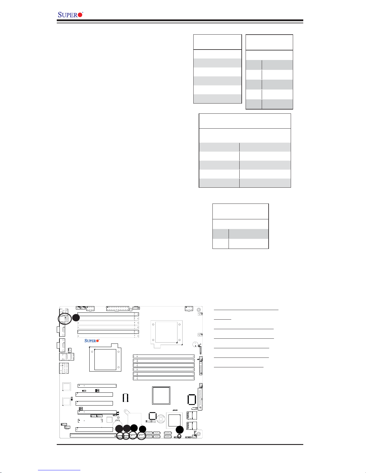
Universal Serial Bus (USB)
There are ten USB 2.0 (Universal
Serial Bus) ports/headers on the
motherboard. Back Panel USB Ports
0/1/2/3 are located at JUSB1. The
other six are Front Panel Accessible
USB headers. USB 4/5 (JUSB 2),
USB 6/7 (JUSB 3), USB 8 (J24) and
USB 9 (J23) provide front panel USB
access. See the tables on the right
for pin defi nitions.
Chassis Intrusion
A Chassis Intrusion header is located
at JL1 on the motherboard. Attach an
appropriate cable from the chassis to
inform you of a chassis intrusion when
the chassis is opened.
Back Panel USB
(USB0/1/2/3)
Pin# Defi nitions
1 +5V
2PO-
3PO+
4 Ground
5N/A
Front Panel USB
(USB8/9)
Pin# Defi nition
1 Vcc
2 Data-
3 Data+
4 Ground
5NA
Front Panel USB
Pin Defi nitions (USB4/5/6/7)
USB4/6
Pin # Defi nition
1 +5V 1 +5V
2 PO- 2 PO-
3 PO+ 3 PO+
4 Ground 4 Ground
5 Key 5 No connection
USB5/7
Pin # Defi nition
Chassis Intrusion
Pin Defi nitions (JL1)
Pin# Defi nition
1 Intrusion Input
2 Ground
Fan5
Fan6
2/3
A
USB
Fan8/CPU2 Fan
LAN2
JPL2
JI2C1
JI2C2
JPL1
JPW2
P2 DIMM1A
P2 DIMM1B
P2 DIMM2A
P2 DIMM2B
P2 DIMM3A
P2 DIMM3B
Slot6 PCI-E x16
Slot5 PCI 33MH
Slot4 PCI 33MH
Slot3 PCI-E X16
1394_2
Slot2 PCI-E X4
Slot1 PCI 33MH
Slot0 SIMLC
1
KB/Mouse
0/1
USB
COM1
COM2
LAN1
AUDIO
82573V
LAN
CTRL
82573L
LAN
CTRL
JC2
CD1
1394_1
JI2C3
JI2C4
X8DA3/i
CPU2
JPW3
SPI BIOS
JPF1
JBT1
Battery
C
USB6/7
JUSB3
B
USB4/5
JUSB2
Super IO
ICH9R
Intel
South
Bridge
USB8
J24
J6
CPU1
P1 DIMM3B
P1 DIMM3A
P1 DIMM2B
P1 DIMM2A
P1 DIMM1B
P1 DIMM1A
Intel IOH
LES2
I-Button
J15
J14
T-SGPIO1
T-SGPIO2
I-SATA5
I-SATA3
I-SATA2
I-SATA1
I-SATA0
USB9
I-SATA4
J23
1068E
SAS CTRL
JWD
JPW1
Fan7/CPU1
SP1
LE1
LES1
J5
JSM2
JSM1
JWOL1
JL1
JPS1
JPS2
A. Backpanel USB
Fan1
0/1/2/3
B. Front Panel USB 4/5
C. Front Panel USB 6/7
D. Front Panel USB 8
JD1
JOH1
E. Front Panel USB 9
Fan2
F. Chassis Intrusion
JF1
Fan3
Floppy
SAS 4~7
SAS 0~3
Fan4
2-16
Page 37
Fan Headers
F
E
D
G
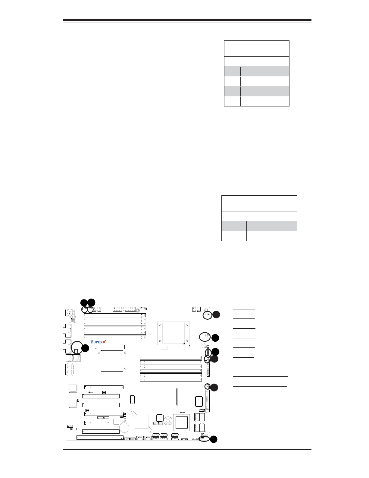
The X8DA3/X8DAi has six chassis/system fan
headers (Fan1 to Fan6) and two CPU fans
(Fan7/Fan8) on the motherboard. All these
4-pin fans headers are backward compatible
with the traditional 3-pin fans. However, fan
speed control is available for 4-pin fans only.
The fan speeds are controlled by Thermal
Management via Hardware Monitoring in the
Advanced Setting in the BIOS. (The Default
setting is Disabled.) See the table on the right
for pin defi nitions.
Power LED/Speaker
Chapter 2: Installation
Fan Header
Pin Defi nitions
Pin# Defi nition
1 Ground
2 +12V
3 Tachometer
4 PWR Modulation
On the JD1 header, pins 1-3 are used for
power LED indication, and pins 4-7 are for
the speaker. See the table on the right for
speaker pin defi nitions. Please note that the
speaker connector pins (4-7) are for use with
an external speaker. If you wish to use the
onboard speaker, you should close pins 6-7
with a jumper.
0/1
COM1
COM2
LAN1
AUDIO
Fan5
Fan6
2/3
USB
Fan8/CPU2 Fan
LAN2
JPL2
JI2C1
JI2C2
JPW2
P2 DIMM1A
P2 DIMM1B
P2 DIMM2A
P2 DIMM2B
P2 DIMM3A
P2 DIMM3B
H
Slot6 PCI-E x16
JPL1
1
Slot5 PCI 33MH
Slot4 PCI 33MH
Slot3 PCI-E X16
1394_1
1394_2
Slot2 PCI-E X4
Slot1 PCI 33MH
Slot0 SIMLC
KB/Mouse
USB
82573V
LAN
CTRL
82573L
LAN
CTRL
JC2
CD1
X8DA3/i
CPU2
JI2C3
JI2C4
JPW3
JPF1
Battery
USB6/7
JUSB3
SPI BIOS
JBT1
USB4/5
JUSB2
Super IO
ICH9R
Intel
South
Bridge
USB8
J24
J6
CPU1
P1 DIMM3B
P1 DIMM3A
P1 DIMM2B
P1 DIMM2A
P1 DIMM1B
P1 DIMM1A
Intel IOH
LES1
LES2
1068E
I-Button
I-SATA3
I-SATA2
SAS CTRL
J14
I-SATA1
I-SATA0
JWD
JL1
J15
T-SGPIO1
T-SGPIO2
I-SATA5
USB9
I-SATA4
J23
Speaker Connector
Pin Setting Defi nition
Pins 6-7 Internal Speaker
Pins 4-7 External Speaker
JPW1
A
Fan1
A. Fan 1
B. Fan 2
C. Fan 3
Fan7/CPU1
SP1
LE1
JD1
JOH1
I
Fan2
B
JF1
D. Fan 4
E. Fan 5
F. F an 6
G. Fan 7 (CPU1 Fan)
H. Fan 8 (CPU2 Fan)
Fan3
C
Floppy
J5
JSM2
SAS 4~7
JSM1
SAS 0~3
JWOL1
JPS1
JPS2
Fan4
I. PWR LED/Speaker
2-17
Page 38
X8DA3/X8DAi User's Manual
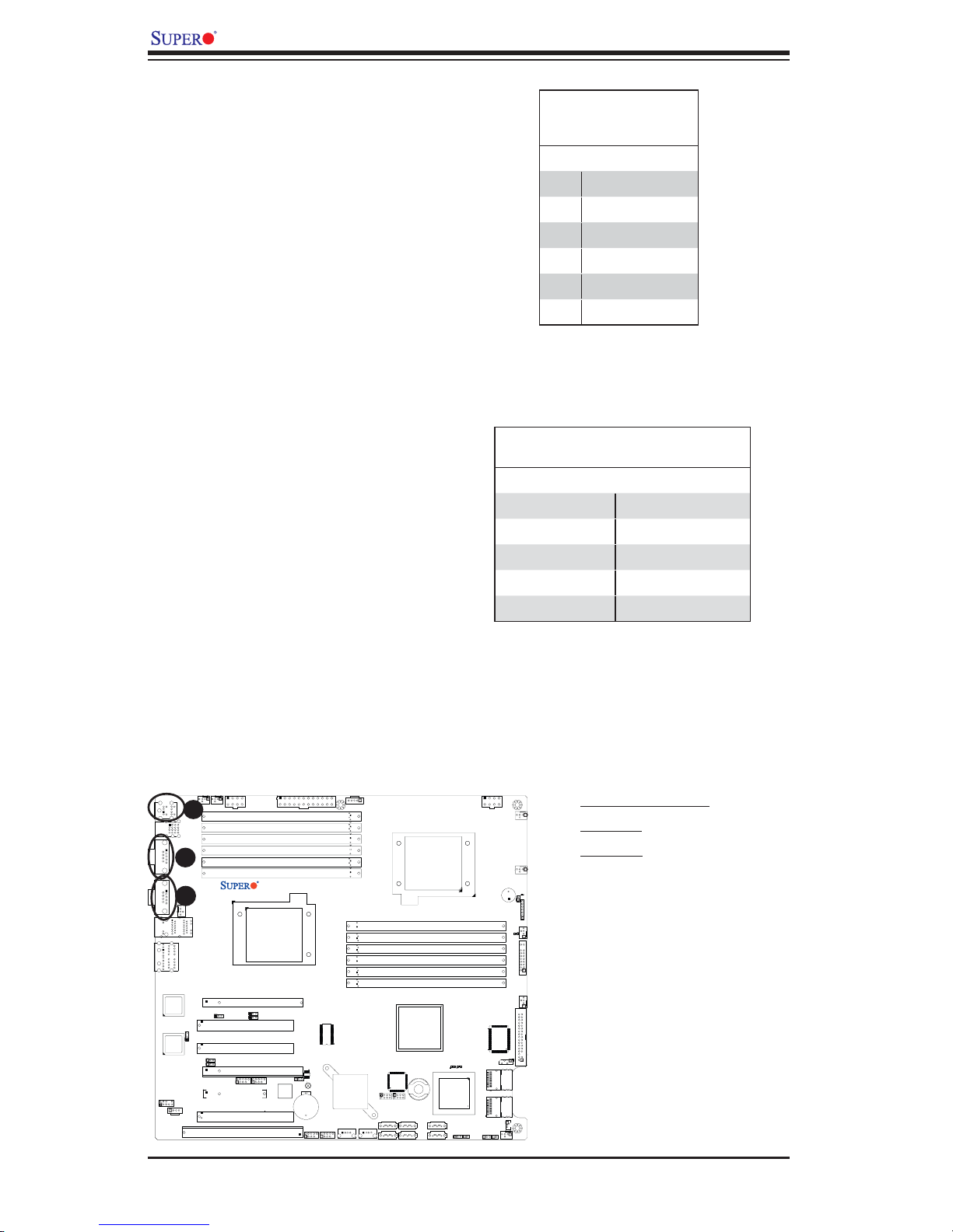
ATX PS/2 Keyboard and PS/2
Mouse Ports
The ATX PS/2 keyboard and the PS/2
mouse are located on the back panel.
See the table on the right for pin defi -
nitions. (The mouse port is above the
keyboard port. See the table on the
right for pin defi nitions.)
Serial Ports
COM1 and COM2 are serial connec-
tors located on the I/O Backpanel.
See the table on the right for pin
defi nitions.
PS/2 Keyboard and
Mouse Port Pin
Defi nitions
Pin# Defi nition
1 Data
2NC
3 Ground
4 VCC
5Clock
6NC
Serial Port Pin Defi nitions
(COM1/COM2)
Pin # Defi nition Pin # Defi nition
1 CDC 6 DSR
2RXD 7RTS
3TXD 8 CTS
4DTR 9RI
5 Ground 10 NC
COM1
COM2
LAN1
AUDIO
(NC: No Connection.)
Fan5
Fan6
JPW2
A
KB/Mouse
0/1
2/3
USB
USB
B
P2 DIMM1A
P2 DIMM1B
P2 DIMM2A
P2 DIMM2B
P2 DIMM3A
P2 DIMM3B
JPW3
X8DA3/i
C
Fan8/CPU2 Fan
Slot6 PCI-E x16
Slot5 PCI 33MH
Slot4 PCI 33MH
Slot3 PCI-E X16
1394_2
Slot2 PCI-E X4
Slot1 PCI 33MH
Slot0 SIMLC
1
1394_1
CPU2
JI2C3
JI2C4
JPF1
Battery
LAN2
82573V
LAN
CTRL
JPL1
JPL2
82573L
LAN
CTRL
JI2C1
JI2C2
JC2
CD1
USB6/7
JUSB3
SPI BIOS
JBT1
USB4/5
JUSB2
Super IO
ICH9R
Intel
South
Bridge
USB8
J24
J6
CPU1
P1 DIMM3B
P1 DIMM3A
P1 DIMM2B
P1 DIMM2A
P1 DIMM1B
P1 DIMM1A
Intel IOH
LES2
I-Button
J15
J14
T-SGPIO1
T-SGPIO2
I-SATA5
I-SATA3
I-SATA2
I-SATA1
I-SATA0
USB9
I-SATA4
J23
1068E
SAS CTRL
JWD
JPW1
Fan1
Fan7/CPU1
SP1
JD1
JOH1
Fan2
LE1
JF1
Fan3
Floppy
LES1
J5
JSM2
SAS 4~7
JSM1
SAS 0~3
JWOL1
JL1
JPS1
JPS2
Fan4
A. Keyboard/Mouse
B. COM1
C. COM2
2-18
Page 39
Chapter 2: Installation
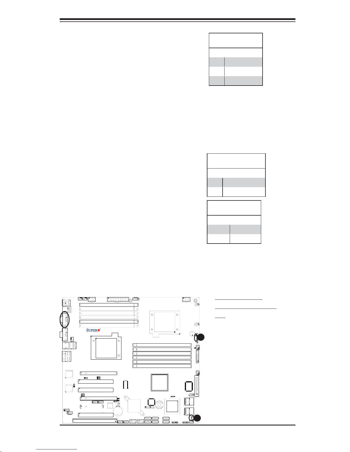
Wake-On-LAN
The Wake-On-LAN header is located
at JWOL1 on the motherboard. You
must also have a LAN card with a
Wake-On-LAN connector and a cable
to use this feature. See the table on
the right for pin defi nitions.
Overheat LED/Fan Fail (JOH1)
The JOH1 header is used to connect
an LED indicator to provide warnings
of chassis overheating or fan failure.
This LED will blink when a fan failure
occurs. Refer to the table on right for
pin defi nitions.
Wake-On-LAN
Pin Defi nitions
Pin# Defi nition
1 +5V Standby
2 Ground
3 Wake-up
Overheat LED
Pin Defi nitions
Pin# Defi nition
1 5vDC
2 OH Active
OH/Fan Fail LED
Pin Defi nitions
State Message
Solid Overheat
Blinking Fan Fail
Fan5
0/1
COM1
Fan6
KB/Mouse
USB
JPW2
2/3
USB
P2 DIMM1A
P2 DIMM1B
P2 DIMM2A
P2 DIMM2B
P2 DIMM3A
P2 DIMM3B
JPW3
X8DA3/i
COM2
Fan8/CPU2 Fan
Slot6 PCI-E x16
Slot5 PCI 33MH
Slot4 PCI 33MH
Slot3 PCI-E X16
1394_2
Slot2 PCI-E X4
Slot1 PCI 33MH
Slot0 SIMLC
1
1394_1
CPU2
JI2C3
JI2C4
JPF1
Battery
USB6/7
LAN1
AUDIO
LAN2
82573V
LAN
CTRL
JPL1
JPL2
82573L
LAN
CTRL
JI2C1
JI2C2
JC2
CD1
JUSB3
SPI BIOS
JBT1
USB4/5
JUSB2
Super IO
ICH9R
Intel
South
Bridge
USB8
J24
J6
JPW1
Fan1
A. Keyboard/Mouse
B. Overheat/Fan Fail
LED
CPU1
P1 DIMM3B
P1 DIMM3A
P1 DIMM2B
P1 DIMM2A
P1 DIMM1B
P1 DIMM1A
Intel IOH
LES2
1068E
I-Button
I-SATA3
I-SATA2
SAS CTRL
J14
I-SATA1
I-SATA0
JWD
J15
T-SGPIO1
T-SGPIO2
I-SATA5
USB9
I-SATA4
J23
Fan7/CPU1
SP1
B
JD1
JOH1
Fan2
LE1
JF1
Fan3
Floppy
LES1
J5
JSM2
SAS 4~7
JSM1
SAS 0~3
A
JWOL1
JL1
JPS1
JPS2
Fan4
2-19
Page 40
X8DA3/X8DAi User's Manual
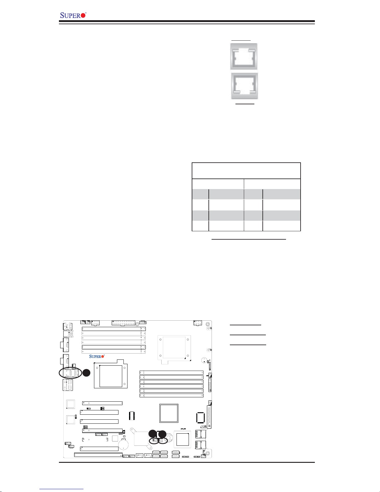
GLAN 1/2 (Giga-bit Ethernet
Ports)
Two G-bit Ethernet ports are located
on the I/O backplane. These ports
accept RJ45 type cables.
T-SGPIO Headers
Two SGPIO (Serial-Link General
Purpose Input/Output) headers (T-
SGPIO-1/T-SGPIO-2) are located at
J14/J15 on the motherboard. These
headers support serial link interfaces
for the onboard SATA and SAS con-
nectors. See the table on the right
for pin defi nitions. Refer to the board
layout below for the location.
GLAN2
GLAN1
T-SGPIO
Pin Defi nitions
Pin# Defi nition Pin Defi nition
1NC 2 NC
3 Ground 4 Data
5 Load 6 Ground
7NC 8 NC
Note: NC= No Connections
Fan5
0/1
USB
COM1
KB/Mouse
2/3
USB
Fan6
JPW2
P2 DIMM1A
P2 DIMM1B
P2 DIMM2A
P2 DIMM2B
P2 DIMM3A
P2 DIMM3B
JPW3
X8DA3/i
COM2
Fan8/CPU2 Fan
LAN1
AUDIO
A
LAN2
82573V
LAN
CTRL
82573L
JC2
JPL1
JPL2
LAN
CTRL
JI2C1
JI2C2
CD1
Slot6 PCI-E x16
Slot5 PCI 33MH
Slot4 PCI 33MH
Slot3 PCI-E X16
1394_2
Slot2 PCI-E X4
Slot1 PCI 33MH
Slot0 SIMLC
1
1394_1
CPU2
JI2C3
JI2C4
SPI BIOS
JPF1
JBT1
Battery
USB6/7
JUSB3
USB4/5
JUSB2
Super IO
ICH9R
Intel
South
Bridge
USB8
J6
CPU1
P1 DIMM3B
P1 DIMM3A
P1 DIMM2B
P1 DIMM2A
P1 DIMM1B
P1 DIMM1A
Intel IOH
LES2
C
B
I-Button
J15
J14
T-SGPIO1
T-SGPIO2
I-SATA5
I-SATA3
I-SATA2
I-SATA1
I-SATA0
USB9
I-SATA4
J24
J23
1068E
SAS CTRL
JWD
JPW1
Fan1
Fan7/CPU1
SP1
JOH1
Fan2
LE1
JF1
Fan3
Floppy
LES1
J5
JSM2
SAS 4~7
JSM1
SAS 0~3
JWOL1
JL1
JPS1
JPS2
Fan4
A. GLAN1/2
B. T-SGPIO-1
C. T-SGPIO-2
JD1
2-20
Page 41
Chapter 2: Installation
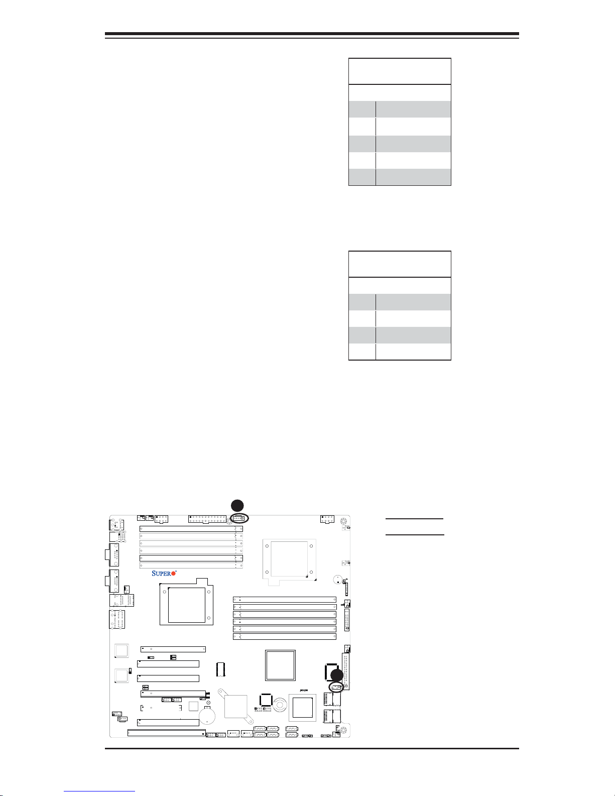
Power SMB (I2C) Connector
Power System Management Bus
2
(I
C) Connector (J6) monitors power
supply, fan and system temperatures.
See the table on the right for pin
defi nitions.
IPMB I2C SMB
A System Management Bus header
for the IPMI slot is located at J5.
Connect the appropriate cable here
to use the IPMB I
your system.
2
C connection on
PWR SMB
Pin Defi nitions
Pin# Defi nition
1Clock
2 Data
3 PWR Fail
4 Ground
5 +3.3V
SMB Header
Pin Defi nitions
Pin# Defi nition
1 Data
2 Ground
3Clock
4 No Connection
Fan5
0/1
COM1
Fan6
KB/Mouse
USB
JPW2
2/3
USB
P2 DIMM1A
P2 DIMM1B
P2 DIMM2A
P2 DIMM2B
P2 DIMM3A
P2 DIMM3B
JPW3
X8DA3/i
COM2
Fan8/CPU2 Fan
Slot6 PCI-E x16
Slot5 PCI 33MH
Slot4 PCI 33MH
Slot3 PCI-E X16
1394_2
Slot2 PCI-E X4
Slot1 PCI 33MH
Slot0 SIMLC
1
1394_1
CPU2
JI2C3
JI2C4
JPF1
Battery
USB6/7
LAN1
AUDIO
LAN2
82573V
LAN
CTRL
JPL1
JPL2
82573L
LAN
CTRL
JI2C1
JI2C2
JC2
CD1
JUSB3
SPI BIOS
JBT1
USB4/5
JUSB2
Super IO
ICH9R
Intel
South
Bridge
USB8
J24
A
J6
CPU1
P1 DIMM3B
P1 DIMM3A
P1 DIMM2B
P1 DIMM2A
P1 DIMM1B
P1 DIMM1A
Intel IOH
LES2
I-Button
J15
J14
T-SGPIO1
T-SGPIO2
I-SATA5
I-SATA3
I-SATA2
I-SATA1
I-SATA0
USB9
I-SATA4
J23
1068E
SAS CTRL
JWD
JPW1
Fan1
Fan7/CPU1
SP1
JD1
JOH1
Fan2
LE1
JF1
Fan3
Floppy
B
LES1
J5
JSM2
SAS 4~7
JSM1
SAS 0~3
JWOL1
JL1
JPS1
JPS2
Fan4
A. PWR SMB
B. IPMB SMB
2-21
Page 42
X8DA3/X8DAi User's Manual
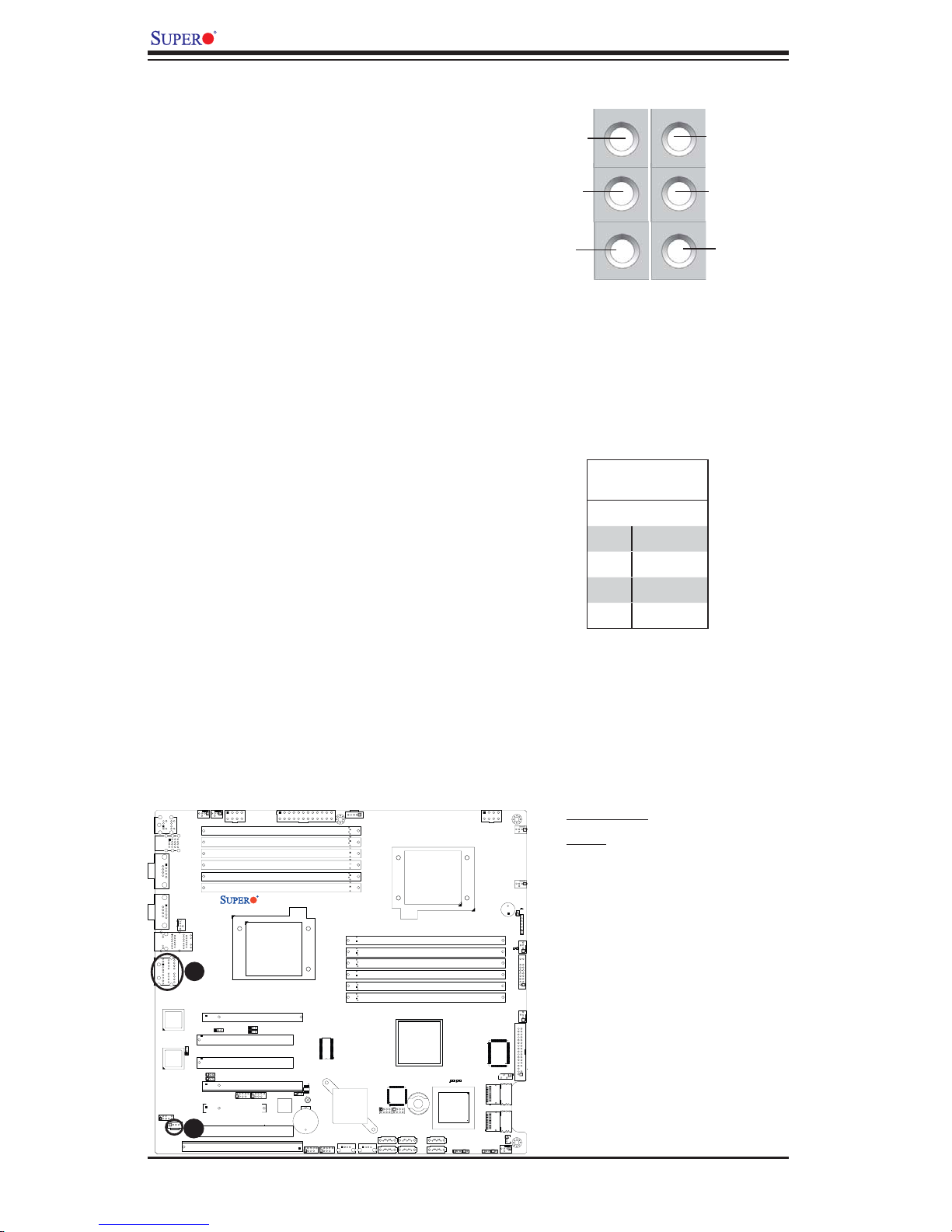
High Defi nition Audio (HD Audio)
This motherboard features a 7.1+2 Chan-
nel High Defi nition Audio (HDA) codecs that
provide 10DAC channels, simultaneously sup-
porting 7.1 sound playback with 2 channels
of independent stereo sound output (multiple
streaming) through the front panel stereo out
for front L&R, rear L&R, center and subwoofer
speakers. Use the Advanced software in-
cluded in the CD-ROM with your motherboard
to enable this function.
CD Header
Orange:
CEN/LFE
Black: Back
Surround
Grey: Side
Surround
Blue: Line-In
Green:Front
Pink: Mic-In
There is a 4-pin CD header (CD1) and a Front
Pane Accessible Audio header (JC2) on the
motherboard. These headers allow you to use
the onboard sound for audio CD playback.
Connect an audio cable from your CD drive
to the CD header that fi ts your cable's con-
nector. Only one CD header can be used at
a time. See the tables at right for pin defi ni-
tions. (For details on FP Audio, please see
the next page.)
COM1
COM2
LAN1
AUDIO
Fan5
Fan6
2/3
USB
Fan8/CPU2 Fan
LAN2
JPW2
P2 DIMM1A
P2 DIMM1B
P2 DIMM2A
P2 DIMM2B
P2 DIMM3A
P2 DIMM3B
KB/Mouse
0/1
USB
JPW3
X8DA3/i
CPU2
A
82573V
LAN
CTRL
82573L
LAN
CTRL
JC2
CD1
Slot6 PCI-E x16
JPL1
JI2C3
1
JI2C4
Slot5 PCI 33MH
JPL2
Slot4 PCI 33MH
JI2C1
JI2C2
Slot3 PCI-E X16
1394_2
Slot2 PCI-E X4
Slot1 PCI 33MH
B
Slot0 SIMLC
1394_1
JPF1
Battery
USB6/7
JUSB3
SPI BIOS
JBT1
USB4/5
JUSB2
Super IO
ICH9R
Intel
South
Bridge
USB8
J24
J6
CPU1
P1 DIMM3B
P1 DIMM3A
P1 DIMM2B
P1 DIMM2A
P1 DIMM1B
P1 DIMM1A
Intel IOH
LES1
LES2
1068E
I-Button
I-SATA3
I-SATA2
SAS CTRL
J14
I-SATA1
I-SATA0
JWD
JL1
J15
T-SGPIO1
T-SGPIO2
I-SATA5
USB9
I-SATA4
J23
CD1 Pin Defi ni-
tion
Pin# Defi nition
1Left
2 Ground
3 Ground
4 Right
JPW1
Fan1
Fan7/CPU1
SP1
JOH1
Fan2
LE1
JF1
Fan3
Floppy
J5
JSM2
SAS 4~7
JSM1
SAS 0~3
JWOL1
JPS1
JPS2
Fan4
A. HD Audio
B. CD
JD1
2-22
Page 43
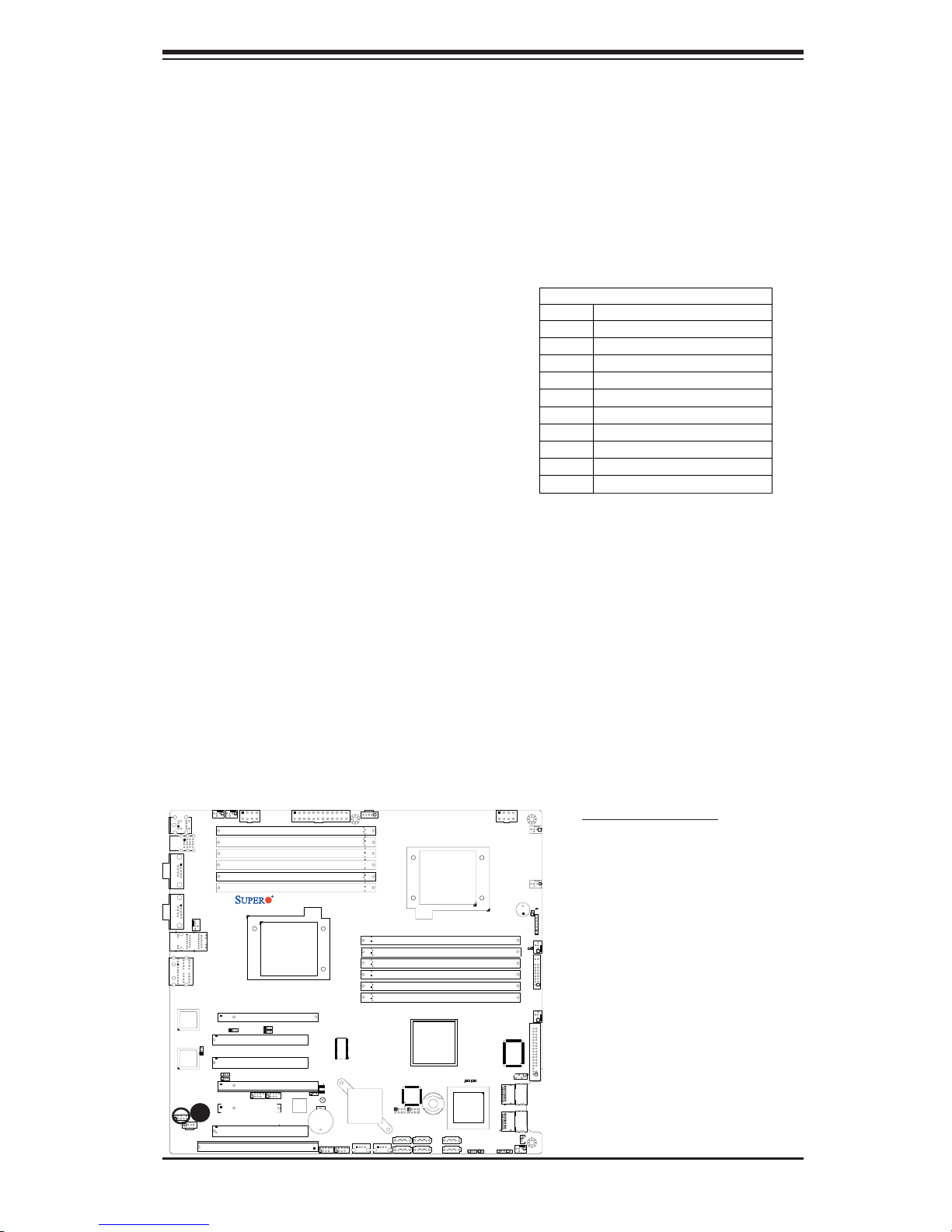
Chapter 2: Installation
Front Panel Audio
When front panel headphones are plugged in, the back panel audio output is dis-
abled. This is done through the FP Audio header (JC2). If the front panel interface
card is not connected to the front panel audio header, jumpers should be installed
on the header (JC2) pin pairs: 1-2, 5-6, and 9-10. If these jumpers are not installed,
the back panel line out connector will be disabled and microphone input Pin 1 will
be left fl oating, which can lead to excessive back panel microphone noise and cross
talk. See the table below for pin defi nitions.
High Definition Front Panel Audio
Pins# Signal
1
2
3
4
5
6
7
8
9
10
MIC_L
AUD_GND
MIC_R
FP_Audio-Detect
Line_2_R
Ground
FP_Jack-Detect
Ke y
Line_2_L
Ground
Fan5
0/1
COM1
Fan6
KB/Mouse
USB
JPW2
2/3
USB
P2 DIMM1A
P2 DIMM1B
P2 DIMM2A
P2 DIMM2B
P2 DIMM3A
P2 DIMM3B
JPW3
X8DA3/i
COM2
Fan8/CPU2 Fan
Slot6 PCI-E x16
Slot5 PCI 33MH
Slot4 PCI 33MH
Slot3 PCI-E X16
1394_2
Slot2 PCI-E X4
Slot1 PCI 33MH
Slot0 SIMLC
1
1394_1
CPU2
JI2C3
JI2C4
JPF1
Battery
USB6/7
LAN1
AUDIO
LAN2
82573V
LAN
CTRL
JPL1
JPL2
82573L
LAN
CTRL
JI2C1
JI2C2
JC2
A
CD1
JUSB3
SPI BIOS
JBT1
USB4/5
JUSB2
Super IO
ICH9R
Intel
South
Bridge
USB8
J24
J6
CPU1
P1 DIMM3B
P1 DIMM3A
P1 DIMM2B
P1 DIMM2A
P1 DIMM1B
P1 DIMM1A
Intel IOH
LES2
I-Button
J15
J14
T-SGPIO1
T-SGPIO2
I-SATA5
I-SATA3
I-SATA2
I-SATA1
I-SATA0
USB9
I-SATA4
J23
1068E
SAS CTRL
JWD
JPW1
Fan1
Fan7/CPU1
SP1
JOH1
Fan2
LE1
JF1
Fan3
Floppy
LES1
J5
JSM2
SAS 4~7
JSM1
SAS 0~3
JWOL1
JL1
JPS1
JPS2
Fan4
A. Front Panel Audio
JD1
2-23
Page 44
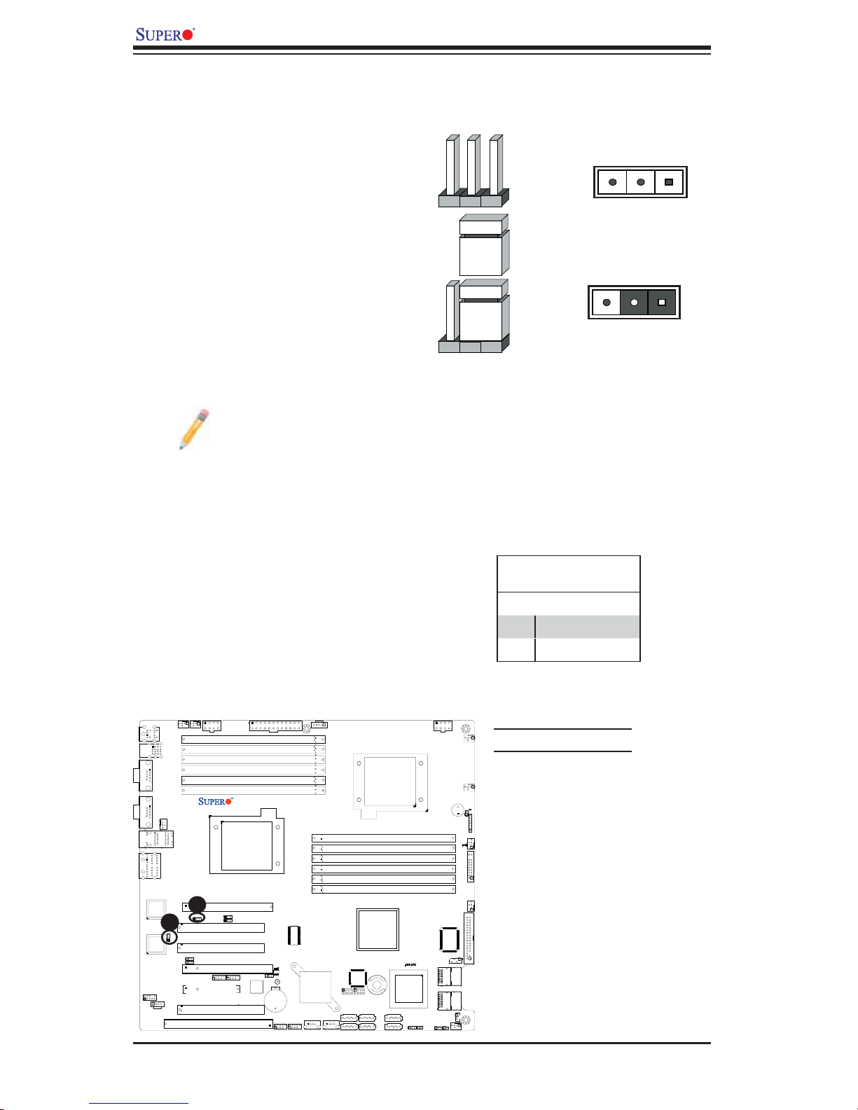
X8DA3/X8DAi User's Manual
Connector
Pins
Jumper
Cap
Setting
2-6 Jumper Settings
Explanation of
Jumpers
To modify the operation of the mother-
board, jumpers can be used to choose
between optional settings. Jumpers cre-
ate shorts between two pins to change
the function of the connector. Pin 1
is identifi ed with a square solder pad
on the printed circuit board. See the
motherboard layout pages for jumper
locations.
Note: On two pin jumpers,
"Closed" means the jumper
is on and "Open" means the
jumper is off the pins.
GLAN Enable/Disable
JPL1/JPL2 enable or disable the GLAN
Port1/GLAN Port2 on the mother-
board. See the table on the right for
jumper settings. The default setting is
Enabled.
3 2 1
3 2 1
Pin 1-2 short
GLAN Enable
Jumper Settings
Pin# Defi nition
1-2 Enabled (default)
2-3 Disabled
Fan5
COM1
COM2
LAN1
AUDIO
Fan6
2/3
USB
Fan8/CPU2 Fan
LAN2
JPL2
JI2C1
JI2C2
A
JPL1
JPW2
P2 DIMM1A
P2 DIMM1B
P2 DIMM2A
P2 DIMM2B
P2 DIMM3A
P2 DIMM3B
Slot6 PCI-E x16
Slot5 PCI 33MH
Slot4 PCI 33MH
Slot3 PCI-E X16
1394_2
Slot2 PCI-E X4
Slot1 PCI 33MH
Slot0 SIMLC
1
KB/Mouse
0/1
USB
82573V
LAN
CTRL
B
82573L
LAN
CTRL
JC2
CD1
1394_1
JI2C3
JI2C4
X8DA3/i
CPU2
JPW3
SPI BIOS
JPF1
JBT1
Battery
USB6/7
JUSB3
USB4/5
JUSB2
Super IO
ICH9R
Intel
South
Bridge
USB8
J24
J6
CPU1
P1 DIMM3B
P1 DIMM3A
P1 DIMM2B
P1 DIMM2A
P1 DIMM1B
P1 DIMM1A
Intel IOH
LES2
I-Button
J15
J14
T-SGPIO1
T-SGPIO2
I-SATA5
I-SATA3
I-SATA2
I-SATA1
I-SATA0
USB9
I-SATA4
J23
1068E
SAS CTRL
JWD
JPW1
LES1
JSM2
JSM1
JL1
JPS1
JPS2
A. GLAN Port 1 Enable
Fan1
B. GLAN Port 2 Enable
Fan7/CPU1
SP1
JD1
JOH1
Fan2
LE1
JF1
Fan3
Floppy
J5
SAS 4~7
SAS 0~3
JWOL1
Fan4
2-24
Page 45
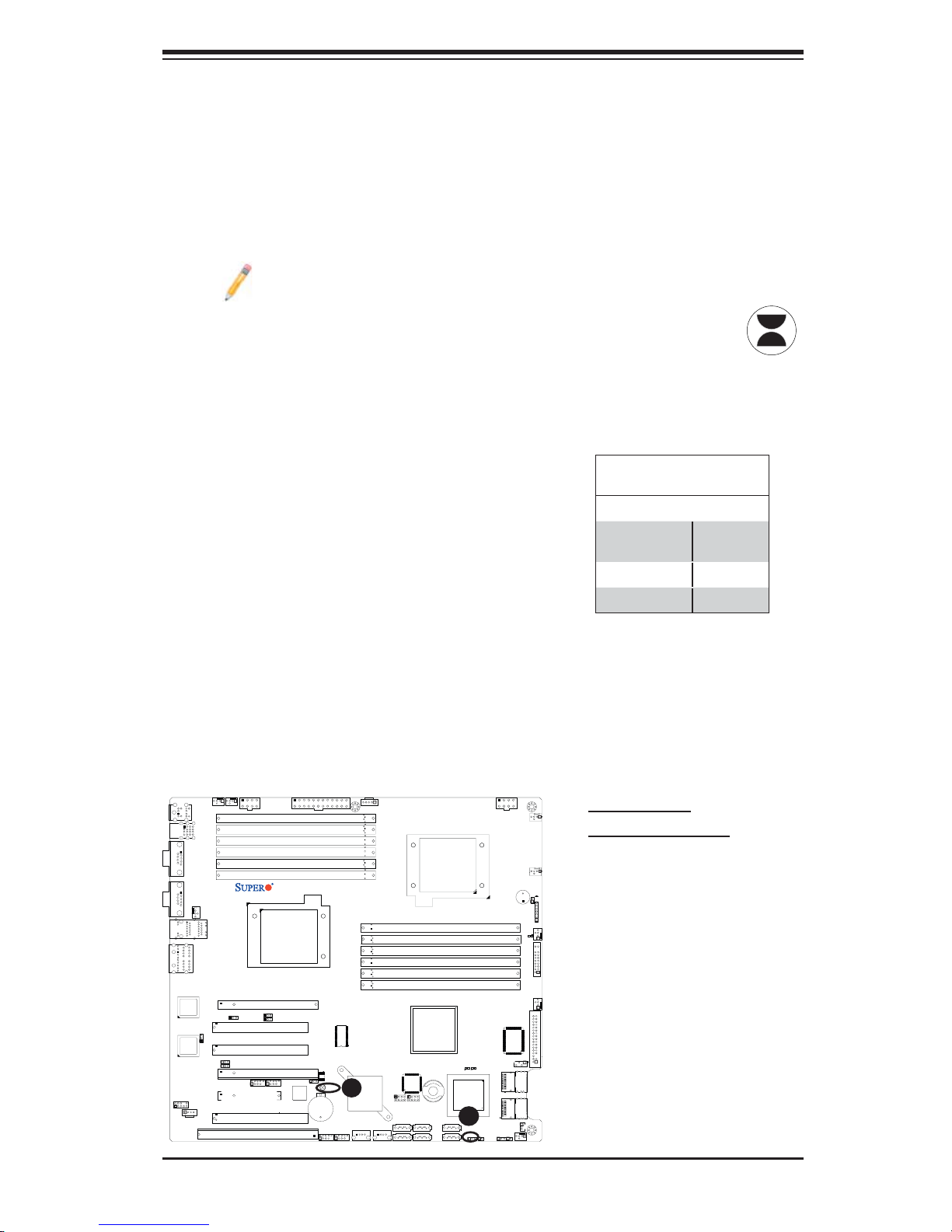
Chapter 2: Installation
CMOS Clear
JBT1 is used to clear CMOS. Instead of pins, this "jumper" consists of contact
pads to prevent the accidental clearing of CMOS. To clear CMOS, use a metal
object such as a small screwdriver to touch both pads at the same time to short
the connection. Always remove the AC power cord from the system before clear-
ing CMOS.
Note: For an ATX power supply, you must completely shut down the sys-
tem, remove the AC power cord and then short JBT1 to clear CMOS.
Watch Dog Enable/Disable
Watch Dog (JWD) is a system monitor that
can reboot the system when a software ap-
plication hangs. Close Pins 1-2 to reset the
system if an application hangs. Close Pins
2-3 to generate a non-maskable interrupt
signal for the application that hangs. See the
table on the right for jumper settings. Watch
Dog must also be enabled in the BIOS.
0/1
COM1
COM2
LAN1
AUDIO
Fan5
Fan6
KB/Mouse
USB
JPW2
2/3
USB
P2 DIMM1A
P2 DIMM1B
P2 DIMM2A
P2 DIMM2B
P2 DIMM3A
P2 DIMM3B
JPW3
X8DA3/i
Fan8/CPU2 Fan
Slot6 PCI-E x16
Slot5 PCI 33MH
Slot4 PCI 33MH
Slot3 PCI-E X16
1394_2
Slot2 PCI-E X4
Slot1 PCI 33MH
Slot0 SIMLC
1
1394_1
CPU2
JI2C3
JI2C4
JPF1
Battery
LAN2
82573V
LAN
CTRL
JPL1
JPL2
82573L
LAN
CTRL
JI2C1
JI2C2
JC2
CD1
USB6/7
JUSB3
SPI BIOS
JBT1
USB4/5
JUSB2
Super IO
A
ICH9R
Intel
South
Bridge
USB8
J24
J6
CPU1
P1 DIMM3B
P1 DIMM3A
P1 DIMM2B
P1 DIMM2A
P1 DIMM1B
P1 DIMM1A
Intel IOH
LES2
1068E
I-Button
I-SATA3
I-SATA2
SAS CTRL
J14
B
I-SATA1
I-SATA0
JWD
J15
T-SGPIO1
T-SGPIO2
I-SATA5
USB9
I-SATA4
J23
Watch Dog
Jumper Settings (JWD)
Jumper Setting Defi nition
Pins 1-2 Reset
(default)
Pins 2-3 NMI
Open Disabled
JPW1
Fan1
Fan7/CPU1
SP1
JOH1
Fan2
LE1
JF1
Fan3
Floppy
LES1
J5
JSM2
SAS 4~7
JSM1
SAS 0~3
JWOL1
JL1
JPS1
JPS2
Fan4
A. Clear CMOS
B. Watch Dog Enable
JD1
2-25
Page 46
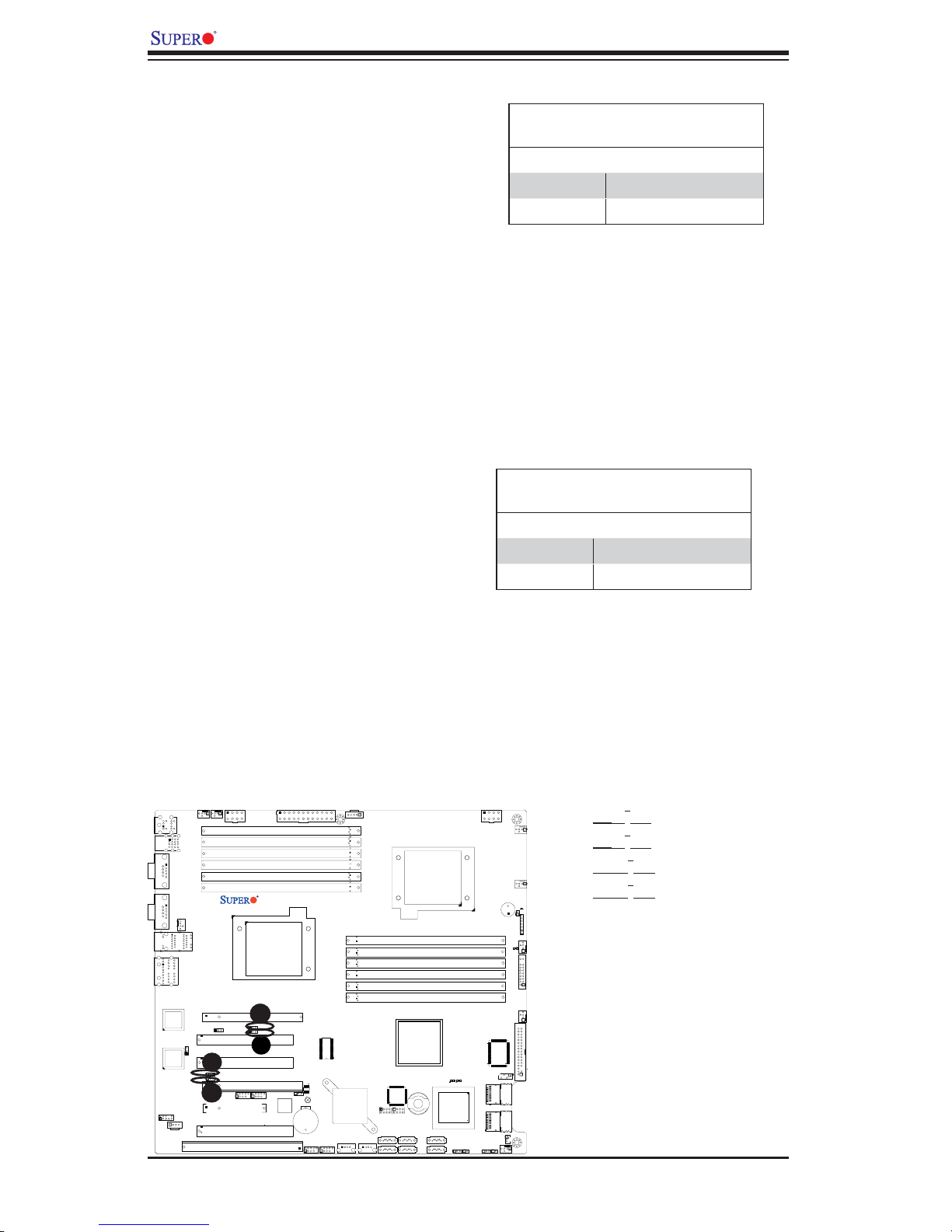
X8DA3/X8DAi User's Manual
D
I2C Bus to PCI-Exp. Slots
Jumpers JI2C1 and JI2C2 allow you to
connect the System Management Bus
2
(I
C) to PCI-Express slots. The default
setting is Open to disable the connec-
tion. See the table on the right for jumper
settings.
I2C to PCI-Exp
Jumper Settings
Jumper Setting Defi nition
1-2 Enabled
2-3 Disabled (Default)
I2C Bus to PCI-X Slots
Jumpers JI2C3, and JI2C4 allow you to
connect the System Management Bus
2
(I
C) to PCI-X slots. The default setting is
Open to disable the connection. See the
table on the right for jumper settings.
COM1
COM2
LAN1
AUDIO
Fan5
Fan6
KB/Mouse
0/1
USB
JPW2
2/3
USB
P2 DIMM1A
P2 DIMM1B
P2 DIMM2A
P2 DIMM2B
P2 DIMM3A
P2 DIMM3B
JPW3
X8DA3/i
Fan8/CPU2 Fan
Slot6 PCI-E x16
Slot5 PCI 33MH
Slot4 PCI 33MH
Slot3 PCI-E X16
1394_2
Slot2 PCI-E X4
Slot1 PCI 33MH
Slot0 SIMLC
1
C
1394_1
CPU2
JI2C3
JI2C4
JPF1
Battery
LAN2
82573V
LAN
CTRL
JPL1
JPL2
82573L
LAN
CTRL
A
JI2C1
JI2C2
B
JC2
CD1
USB6/7
JUSB3
SPI BIOS
JBT1
USB4/5
JUSB2
Super IO
ICH9R
Intel
South
Bridge
USB8
J24
J6
CPU1
P1 DIMM3B
P1 DIMM3A
P1 DIMM2B
P1 DIMM2A
P1 DIMM1B
P1 DIMM1A
Intel IOH
I-Button
J15
J14
T-SGPIO1
T-SGPIO2
I-SATA5
I-SATA3
I-SATA2
I-SATA1
I-SATA0
USB9
I-SATA4
J23
LES2
SAS CTRL
1068E
I2C to PCI-X
Jumper Settings
Jumper Setting Defi nition
1-2 Enabled
2-3 Disabled (Default)
2
A. JI
B. JI
2
C1
C2
JPW1
Fan1
C. JI2C3
Fan7/CPU1
SP1
JD1
JOH1
Fan2
LE1
JF1
Fan3
Floppy
LES1
J5
JSM2
SAS 4~7
JSM1
SAS 0~3
JWD
JWOL1
JL1
JPS1
JPS2
Fan4
D. JI
2
C4
2-26
Page 47
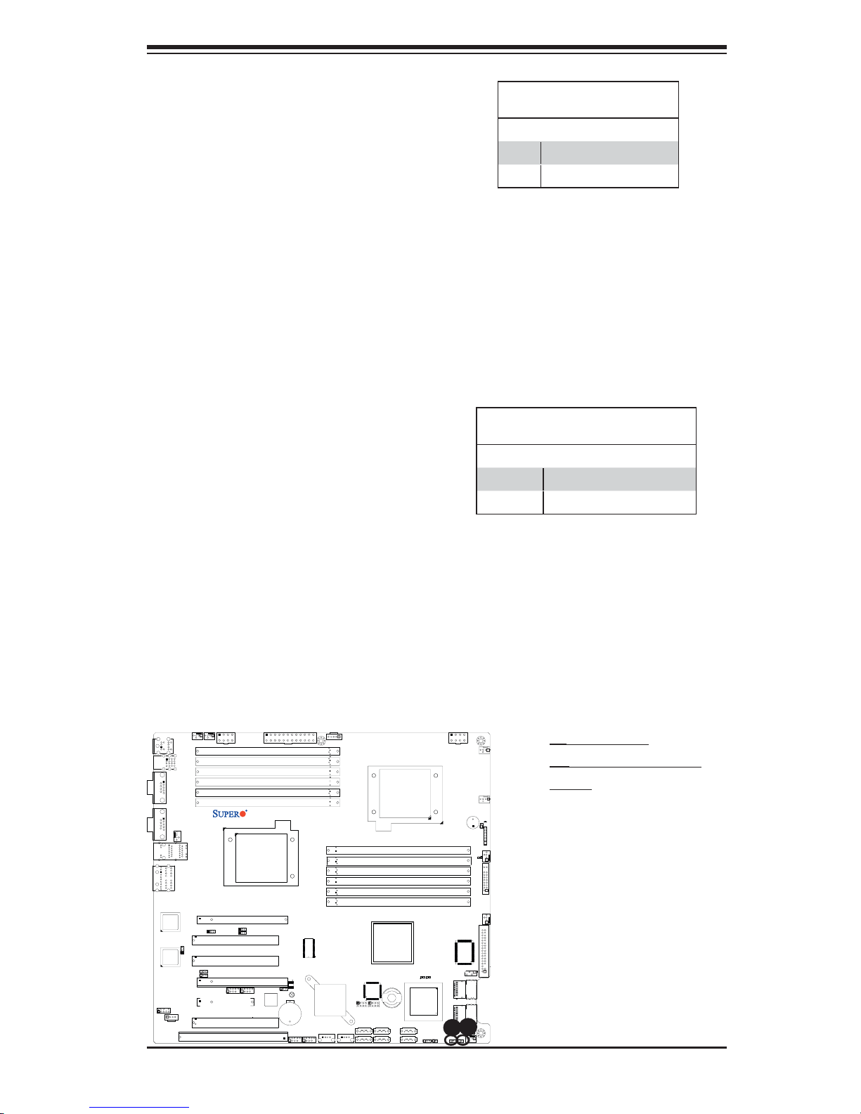
Chapter 2: Installation
SAS Enable/Disable
Jumper JPS1 allows you to enable or
disable the onboard SAS connections.
The default setting is Pins 1-2 to enable
the connection. See the table on the right
for jumper settings.
SAS RAID Select
Jumper JPS2 allows you to select RAID
Confi guration settings for the onboard
SAS connections. See the table on the
right for jumper settings.
SAS Enable
Jumper Settings
Jumper Setting Defi nition
1-2 SAS Enabled (Default)
2-3 SAS Disabled
SAS RAID Confi g. Select
Jumper Settings
Jumper Setting Defi nition
Open Integrated Target Mode (IT)
Closed Software RAID (SR)
Fan5
0/1
COM1
Fan6
KB/Mouse
USB
JPW2
2/3
USB
P2 DIMM1A
P2 DIMM1B
P2 DIMM2A
P2 DIMM2B
P2 DIMM3A
P2 DIMM3B
JPW3
X8DA3/i
COM2
Fan8/CPU2 Fan
Slot6 PCI-E x16
Slot5 PCI 33MH
Slot4 PCI 33MH
Slot3 PCI-E X16
1394_2
Slot2 PCI-E X4
Slot1 PCI 33MH
Slot0 SIMLC
1
1394_1
CPU2
JI2C3
JI2C4
JPF1
Battery
USB6/7
LAN1
AUDIO
LAN2
82573V
LAN
CTRL
JPL1
JPL2
82573L
LAN
CTRL
JI2C1
JI2C2
JC2
CD1
JUSB3
SPI BIOS
JBT1
USB4/5
JUSB2
Super IO
ICH9R
Intel
South
Bridge
USB8
J24
J6
CPU1
P1 DIMM3B
P1 DIMM3A
P1 DIMM2B
P1 DIMM2A
P1 DIMM1B
P1 DIMM1A
Intel IOH
LES2
I-Button
J15
J14
T-SGPIO1
T-SGPIO2
I-SATA5
I-SATA3
I-SATA2
I-SATA1
I-SATA0
USB9
I-SATA4
J23
1068E
SAS CTRL
JWD
JPW1
Fan1
Fan7/CPU1
SP1
JD1
JOH1
Fan2
LE1
JF1
Fan3
Floppy
LES1
J5
JSM2
SAS 4~7
JSM1
SAS 0~3
B
A
JWOL1
JL1
JPS1
JPS2
Fan4
A. SAS Enable
B. SAS RAID Confi g.
Select
2-27
Page 48
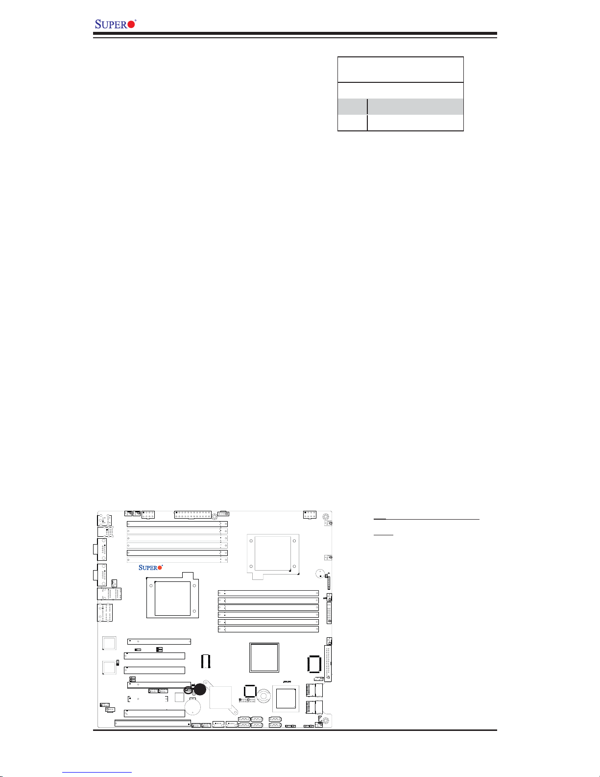
X8DA3/X8DAi User's Manual
1394_1/1394_2 Enable
Jumper JPF1 allows you to enable or
disable 1394_1/1394_2. The default
setting is Pins 1-2 to enable the con-
nection. See the table on the right for
jumper settings.
1394 Enable
Jumper Settings
Jumper Setting Defi nition
1-2 Normal (Default)
2-3 1394 Disabled
Fan5
COM1
Fan6
KB/Mouse
0/1
USB
JPW2
2/3
USB
P2 DIMM1A
P2 DIMM1B
P2 DIMM2A
P2 DIMM2B
P2 DIMM3A
P2 DIMM3B
JPW3
X8DA3/i
COM2
Fan8/CPU2 Fan
Slot6 PCI-E x16
Slot5 PCI 33MH
Slot4 PCI 33MH
Slot3 PCI-E X16
1394_2
Slot2 PCI-E X4
Slot1 PCI 33MH
Slot0 SIMLC
1
1394_1
CPU2
JI2C3
JI2C4
SPI BIOS
A
JPF1
JBT1
Battery
USB6/7
JUSB3
LAN1
AUDIO
LAN2
82573V
LAN
CTRL
JPL1
JPL2
82573L
LAN
CTRL
JI2C1
JI2C2
JC2
CD1
USB4/5
JUSB2
Super IO
ICH9R
Intel
South
Bridge
USB8
J24
J6
JPW1
Fan1
A. 1394_1/1394_2 En-
able
CPU1
Fan7/CPU1
SP1
JD1
P1 DIMM3B
P1 DIMM3A
P1 DIMM2B
P1 DIMM2A
P1 DIMM1B
P1 DIMM1A
JOH1
Fan2
LE1
JF1
Fan3
Intel IOH
Floppy
LES1
LES2
1068E
I-Button
I-SATA3
I-SATA2
SAS CTRL
J14
I-SATA1
I-SATA0
JWD
J15
T-SGPIO1
T-SGPIO2
I-SATA5
USB9
I-SATA4
J23
J5
JSM2
SAS 4~7
JSM1
SAS 0~3
JWOL1
JL1
JPS1
JPS2
Fan4
2-28
Page 49
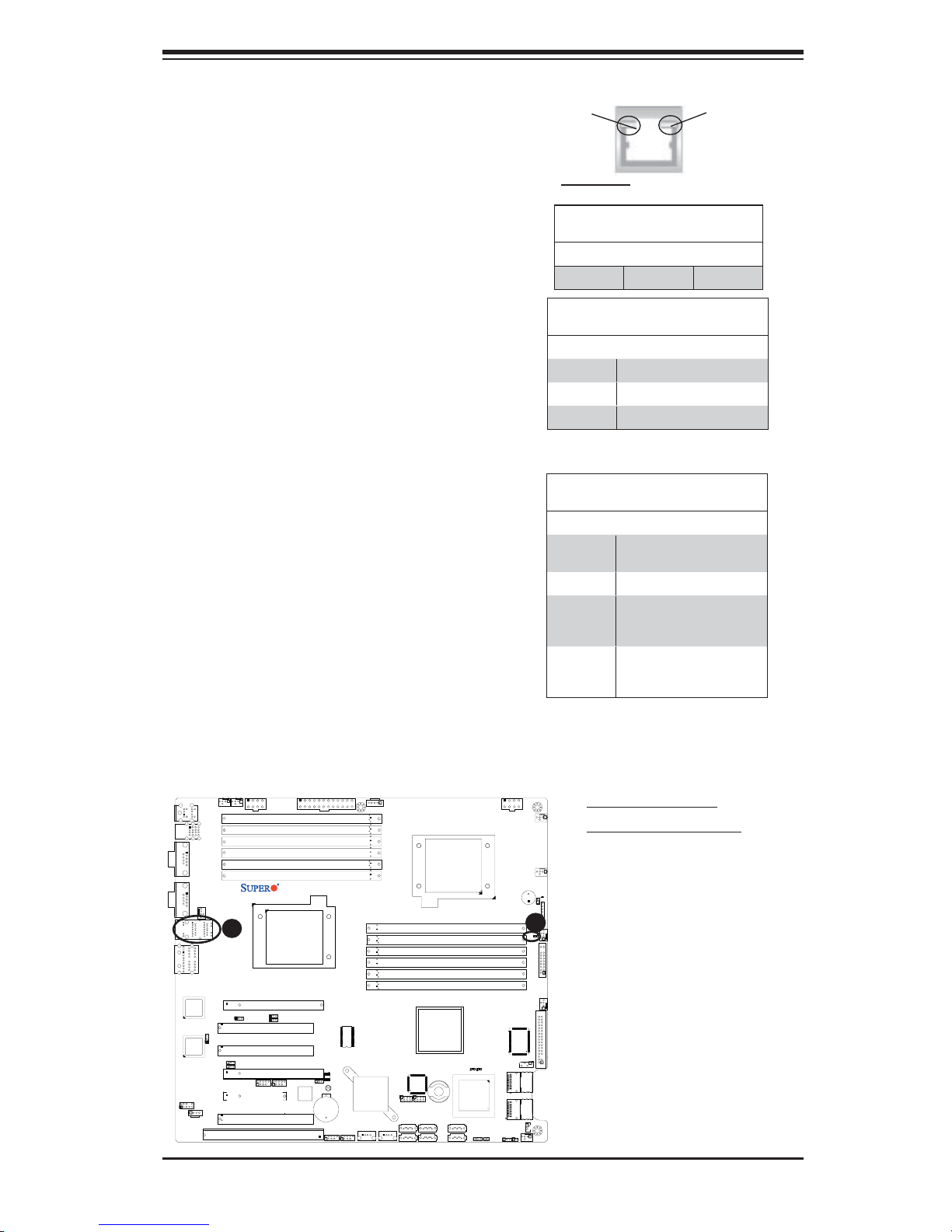
Chapter 2: Installation
2-7 Onboard Indicators
GLAN LEDs
There are two GLAN ports on the moth-
erboard. Each Gigabit Ethernet LAN port
has two LEDs. The green LED indicates
activity, while the Link LED may be green,
amber or off to indicate the speed of the
connection. See the tables at right for
more information.
Onboard Power LED
An Onboard Power LED is located at LE1
on the motherboard. When this LED is lit,
the system is on. Be sure to turn off the
system and unplug the power cord before
removing or installing components. See
the tables at right for more information.
Activity
LED
Link
LED
Rear View (when facing the
rear side of the chassis)
GLAN Activity Indicator
LED Settings
Color Status Defi nition
Green Flashing Active
GLAN Link Indicator
LED Settings
LED Color Defi nition
Off No Connection or 10 Mbps
Green 100 Mbps
Amber 1 Gbps
Onboard PWR LED Indicator (LE1)
LED Color Defi nition
Off System Off (PWR cable
Green System On
Green:
Flashing
Quickly
Green:
Flashing
Slowly
not connected)
ACPI S1 State
ACPI S3 (STR) State
Fan5
0/1
COM1
COM2
LAN1
AUDIO
Fan6
Fan8/CPU2 Fan
A
LAN2
JPL2
JI2C1
JI2C2
JPL1
JPW2
P2 DIMM1A
P2 DIMM1B
P2 DIMM2A
P2 DIMM2B
P2 DIMM3A
P2 DIMM3B
Slot6 PCI-E x16
Slot5 PCI 33MH
Slot4 PCI 33MH
Slot3 PCI-E X16
1394_2
Slot2 PCI-E X4
Slot1 PCI 33MH
Slot0 SIMLC
1
1394_1
KB/Mouse
2/3
USB
USB
82573V
LAN
CTRL
82573L
LAN
CTRL
JC2
CD1
X8DA3/i
CPU2
JI2C3
JI2C4
JPW3
JPF1
Battery
USB6/7
JUSB3
SPI BIOS
JBT1
USB4/5
JUSB2
Super IO
ICH9R
Intel
South
Bridge
USB8
J24
J6
CPU1
P1 DIMM3B
P1 DIMM3A
P1 DIMM2B
P1 DIMM2A
P1 DIMM1B
P1 DIMM1A
Intel IOH
LES2
I-Button
J15
J14
T-SGPIO1
T-SGPIO2
I-SATA5
I-SATA3
I-SATA2
I-SATA1
I-SATA0
USB9
I-SATA4
J23
1068E
SAS CTRL
JWD
JPW1
Fan1
Fan7/CPU1
SP1
JOH1
B
Fan2
LE1
JF1
Fan3
Floppy
LES1
J5
JSM2
SAS 4~7
JSM1
SAS 0~3
JWOL1
JL1
JPS1
JPS2
Fan4
A. GLAN Port LEDs
B. Onboard Power LED
JD1
2-29
Page 50
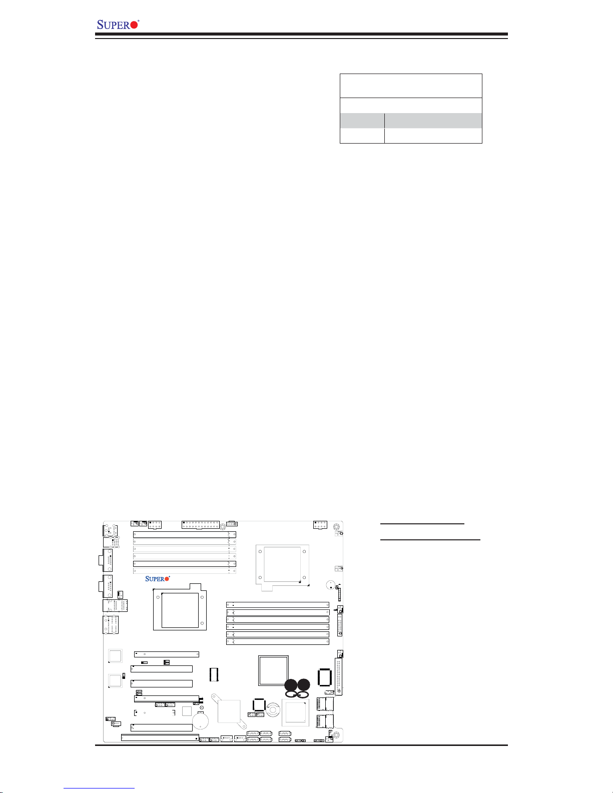
X8DA3/X8DAi User's Manual
SAS LED Indicators
Two Onboard SAS LED are located at
LES1/LES2 on the motherboard. When
this LES1 is lit, SAS Connections 0~3 are
active. When this LES2 is lit, SAS Con-
nections 4~7 are active. See the tables
at right for more information.
Onboard SAS LED Indicators
(LES1/LES2) Settings
LED Color Defi nition
LES1 SAS#0~3: Active
LES2 SAS#4~7: Active
Fan5
0/1
USB
COM1
KB/Mouse
2/3
USB
Fan6
JPW2
P2 DIMM1A
P2 DIMM1B
P2 DIMM2A
P2 DIMM2B
P2 DIMM3A
P2 DIMM3B
JPW3
X8DA3/i
COM2
Fan8/CPU2 Fan
Slot6 PCI-E x16
Slot5 PCI 33MH
Slot4 PCI 33MH
Slot3 PCI-E X16
1394_2
Slot2 PCI-E X4
Slot1 PCI 33MH
Slot0 SIMLC
1
1394_1
CPU2
JI2C3
JI2C4
SPI BIOS
JPF1
JBT1
Battery
USB6/7
JUSB3
LAN1
AUDIO
LAN2
82573V
LAN
CTRL
82573L
JC2
JPL1
JPL2
LAN
CTRL
JI2C1
JI2C2
CD1
USB4/5
JUSB2
Super IO
ICH9R
Intel
South
Bridge
USB8
J6
JPW1
Fan1
A. GLAN Port LEDs
B. Onboard Power LED
CPU1
Fan7/CPU1
SP1
JD1
P1 DIMM3B
P1 DIMM3A
P1 DIMM2B
P1 DIMM2A
P1 DIMM1B
P1 DIMM1A
JOH1
Fan2
LE1
JF1
Fan3
Intel IOH
A
B
LES1
LES2
1068E
I-Button
I-SATA3
I-SATA2
SAS CTRL
J14
I-SATA1
I-SATA0
JWD
JL1
J15
T-SGPIO1
T-SGPIO2
I-SATA5
USB9
I-SATA4
J24
J23
Floppy
J5
JSM2
SAS 4~7
JSM1
SAS 0~3
JWOL1
JPS1
JPS2
Fan4
2-30
Page 51
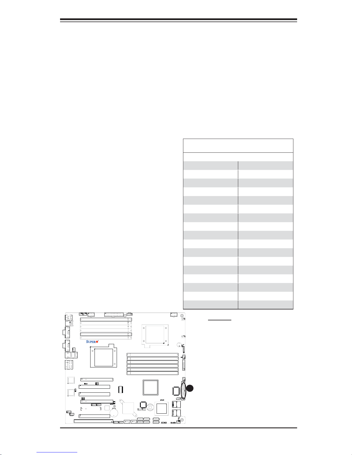
Chapter 2: Installation
2-8 Floppy Drive, SIMLP, Serial ATA and Hard Disk
Drive Connections
Note the following when connecting the fl oppy and hard disk drive cables:
•
The fl oppy disk drive cable has seven twisted wires.
A red mark on a wire typically designates the location of pin 1.
•
A single fl oppy disk drive ribbon cable has 34 wires and two connectors to
•
provide for two fl oppy disk drives. The connector with twisted wires always
connects to drive A, and the connector that does not have twisted wires always
connects to drive B.
Floppy Connector
The fl oppy connector is located close
to the Front Panel Control on the
motherboard. See the table on the
right for pin defi nitions.
Pin# Defi nition Pin # Defi nition
1 Ground 2 FDHDIN
3 Ground 4 Reserved
5 Key 6 FDEDIN
7 Ground 8 Index
9 Ground 10 Motor Enable
11 Ground 12 Drive Select B
13 Ground 14 Drive Select B
15 Ground 16 Motor Enable
17 Ground 18 DIR
19 Ground 20 STEP
21 Ground 22 Write Data
23 Ground 24 Write Gate
25 Ground 26 Track 00
27 Ground 28 Write Protect
29 Ground 30 Read Data
31 Ground 32 Side 1 Select
33 Ground 34 Diskette
Floppy Drive Connector
Pin Defi nitions
Fan5
Fan6
JPW2
KB/Mouse
0/1
USB
COM1
COM2
LAN1
AUDIO
82573V
LAN
CTRL
82573L
LAN
CTRL
JC2
CD1
2/3
USB
Fan8/CPU2 Fan
JPL2
JI2C2
P2 DIMM1A
P2 DIMM1B
P2 DIMM2A
P2 DIMM2B
P2 DIMM3A
P2 DIMM3B
LAN2
Slot6 PCI-E x16
JPL1
Slot5 PCI 33MH
Slot4 PCI 33MH
JI2C1
Slot3 PCI-E X16
1394_2
Slot2 PCI-E X4
Slot1 PCI 33MH
Slot0 SIMLC
1
1394_1
X8DA3/i
CPU2
JI2C3
JI2C4
JPW3
SPI BIOS
JPF1
JBT1
Battery
USB6/7
JUSB3
USB4/5
J6
CPU1
P1 DIMM3B
P1 DIMM3A
P1 DIMM2B
P1 DIMM2A
P1 DIMM1B
P1 DIMM1A
Super IO
ICH9R
Intel
South
Bridge
USB8
J24
JUSB2
Intel IOH
I-Button
J15
J14
T-SGPIO1
T-SGPIO2
I-SATA5
I-SATA3
I-SATA4
I-SATA2
I-SATA1
I-SATA0
USB9
J23
LES2
1068E
SAS CTRL
JWD
JPW1
Fan1
Fan7/CPU1
SP1
JD1
JOH1
Fan2
LE1
JF1
Fan3
A
Floppy
LES1
J5
JSM2
SAS 4~7
JSM1
SAS 0~3
JWOL1
JL1
JPS1
JPS2
Fan4
A. Floppy
2-31
Page 52
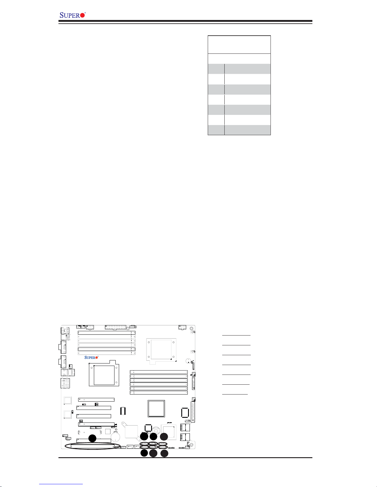
X8DA3/X8DAi User's Manual
G
F
E
D
Serial ATA Ports
Six Serial ATA Ports (I-SATA0~I-
SATA 5) are located at JS1~JS6
on the motherboard. These ports
provide serial-link signal transmis-
sion, which is faster than that of the
traditional Parallel ATA. See the table
on the right for pin defi nitions.
SIMLC IPMI Slot
The SIMLC IPMI (Supermicro Intel-
ligent Management) Slot is located at
Slot 0 on the motherboard. Refer to
the layout below for the SIMLC IPMI
Slot location.
Serial ATA
Pin Defi nitions
Pin# Defi nition
1 Ground
2 TX_P
3 TX_N
4 Ground
5 RX_N
6 RX_P
7 Ground
Fan5
Fan6
JPW2
KB/Mouse
0/1
2/3
USB
USB
COM1
COM2
LAN1
AUDIO
82573V
LAN
CTRL
82573L
LAN
CTRL
JC2
CD1
Fan8/CPU2 Fan
LAN2
JPL2
JI2C1
JI2C2
JPL1
P2 DIMM1A
P2 DIMM1B
P2 DIMM2A
P2 DIMM2B
P2 DIMM3A
P2 DIMM3B
Slot6 PCI-E x16
Slot5 PCI 33MH
Slot4 PCI 33MH
Slot3 PCI-E X16
1394_2
Slot2 PCI-E X4
Slot1 PCI 33MH
Slot0 SIMLC
1
1394_1
X8DA3/i
CPU2
JI2C3
JI2C4
JPW3
Super IO
SPI BIOS
JPF1
JBT1
Battery
USB6/7
USB4/5
JUSB2
JUSB3
ICH9R
Intel
South
Bridge
USB8
J6
JPW1
Fan1
A. I-SATA0
B. I-SATA1
CPU1
P1 DIMM3B
P1 DIMM3A
P1 DIMM2B
P1 DIMM2A
P1 DIMM1B
P1 DIMM1A
Intel IOH
LES2
1068E
I-Button
I-SATA3
I-SATA2
SAS CTRL
J14
B
I-SATA1
I-SATA0
A
C
J15
T-SGPIO1
T-SGPIO2
I-SATA5
USB9
I-SATA4
J24
J23
Fan7/CPU1
SP1
JD1
JOH1
Fan2
LE1
JF1
Fan3
Floppy
LES1
J5
JSM2
SAS 4~7
JSM1
SAS 0~3
JWD
JWOL1
JL1
JPS1
JPS2
Fan4
C. I-SATA2
D. I-SATA3
E. I-SATA4
F. I -S ATA 5
G. SIMLC
2-32
Page 53

Chapter 3: Troubleshooting
Chapter 3
Troubleshooting
3-1 Troubleshooting Procedures
Use the following procedures to troubleshoot your system. If you have followed all
of the procedures below and still need assistance, refer to the ‘Technical Support
Procedures’ and/or ‘Returning Merchandise for Service’ section(s) in this chapter.
Note: Always disconnect the power cord before adding, changing or installing any
hardware components.
Before Power On
Make sure that there are no short circuits between the motherboard and
1.
chassis.
Disconnect all ribbon/wire cables from the motherboard, including those for
2.
the keyboard and mouse.
Remove all add-on cards.
3.
Install CPU 1 fi rst (making sure it is fully seated) and connect the chassis
4.
speaker and the power LED to the motherboard. (Check all jumper settings
as well.)
No Power
Make sure that no short circuits between the motherboard and the chassis.
1.
Make sure that all jumpers are set to their default positions.
2.
Check that the 115V/230V switch on the power supply is properly set.
3.
Turn the power switch on and off to test the system.
4.
The battery on your motherboard may be old. Check to verify that it still sup-
5.
plies ~3VDC. If it does not, replace it with a new one.
3-1
Page 54

X8DA3/X8DAi User's Manual
No Video
If the power is on but you have no video, remove all the add-on cards and
1.
cables.
Use the speaker to determine if any beep codes exist. Refer to the Appendix
2.
for details on beep codes.
Losing the System’s Setup Confi guration
Make sure that you are using a high quality power supply. A poor quality
1.
power supply may cause the system to lose the CMOS setup information.
Refer to Section 1-6 for details on recommended power supplies.
The battery on your motherboard may be old. Check to verify that it still sup-
2.
plies ~3VDC. If it does not, replace it with a new one.
If the above steps do not fi x the Setup Confi guration problem, contact your
3.
vendor for repairs.
Memory Errors
Make sure that the DIMM modules are properly and fully installed.
1.
Check if different speeds of DIMMs have been installed and check if the BIOS
2.
setup is confi gured for the fastest speed of RAM used. (It is recommended to
use the same RAM speed for all DIMMs in the system.)
Make sure you are using the correct type of DDR3 Registered ECC 1333
3.
MHz/1066 MHz/800 MHz SDRAM (recommended by the manufacturer.)
Check for bad DIMM modules or slots by swapping a single module between
4.
all memory slots and check the results.
Make sure that all memory modules are fully seated in their slots. Make sure
5.
to follow the instructions given on DIMM population in Section 2-3 in Chapter
2.
Check the position of the 115V/230V switch on the power supply.
6.
3-2
Page 55

Chapter 3: Troubleshooting
3-2 Technical Support Procedures
Before contacting Technical Support, please take the following steps. Also, please
note that as a motherboard manufacturer, Supermicro does not sell directly to end-
users, so it is best to fi rst check with your distributor or reseller for troubleshooting
services. They should know of any possible problem(s) with the specifi c system
confi guration that was sold to you.
Please go through the ‘Troubleshooting Procedures’ and 'Frequently Asked
1.
Question' (FAQ) sections in this chapter or see the FAQs on our web site
(
http://www.supermicro.com/support/faqs/) before contacting Technical Sup-
port.
BIOS upgrades can be downloaded from our web site at
2.
supermicro.com/support/bios/
If you still cannot resolve the problem, include the following information when
3.
contacting Supermicro for technical support:
Motherboard model and PCB revision number
•
BIOS release date/version (this can be seen on the initial display when your
•
system fi rst boots up)
System confi guration
•
An example of a Technical Support form is on our web site at
•
supermicro.com/support/contact.cfm).
Distributors: For immediate assistance, please have your account number ready
•
when placing a call to our technical support department. We can be reached by
e-mail at [email protected] or by fax at: (408) 503-8000, option 2.
).
(http://www.
(http://www.
3-3 Frequently Asked Questions
Question: What are the various types of memory that my motherboard can
support?
Answer: The X8DA3/X8DAi has 12 240-pin DIMM slots that support DDR3 Regis-
tered ECC 1333 MHz/1066 MHz/800 MHz SDRAM modules. It is strongly recom-
mended that you do not mix memory modules of different speeds and sizes. Please
follow all memory installation instructions given on Section 2-3 in Chapter 2.
3-3
Page 56
X8DA3/X8DAi User's Manual
Question: How do I update my BIOS?
Answer: It is recommended that you do not upgrade your BIOS if you are not
experiencing any problems with your system. Updated BIOS fi les are located on
our web site at
BIOS warning message and the information on how to update your BIOS on our
web site. Also, check the current BIOS revision and make sure it is newer than
your BIOS before downloading. Select your motherboard model and download
the BIOS fi le to your computer. Unzip the BIOS fi les onto a bootable fl oppy and
reboot your system. Follow the Readme.txt to continue fl ashing the BIOS.
(http://www.supermicro.com/support/bios/). Please check our
Warning: Do not shut down or reset the system while updating the BIOS
to prevent possible system boot failure!)
Note: The SPI BIOS chip used on this motherboard cannot be removed.
Send your motherboard back to our RMA Department at Supermicro for
repair.
Question: What's on the CD that came with my motherboard?
Answer: The supplied compact disc has quite a few drivers and programs that
will greatly enhance your system. We recommend that you review the CD and
install the applications you need. Applications on the CD include chipset drivers
for the Windows OS, security and audio drivers.
3-4 Returning Merchandise for Service
A receipt or copy of your invoice marked with the date of purchase is required be-
fore any warranty service will be rendered. You can obtain service by calling your
vendor for a Returned Merchandise Authorization (RMA) number. When returning
to the manufacturer, the RMA number should be prominently displayed on the
outside of the shipping carton, and mailed prepaid or hand-carried. Shipping and
handling charges will be applied for all orders that must be mailed when service
is complete.
This warranty only covers normal consumer use and does not cover damages in-
curred in shipping or from failure due to the alternation, misuse, abuse or improper
maintenance of products.
During the warranty period, contact your distributor fi rst for any product problems.
3-4
Page 57

Appendix A: BIOS POST Error Codes
Appendix A
BIOS POST Error Codes
This section lists the POST (Power On Self Test) codes for the AMI BIOS. POST
codes are divided into two categories: recoverable and terminal.
Recoverable POST Errors
When a recoverable type of error occurs during POST, the BIOS will display an
POST code that describes the problem. BIOS may also issue one of the following
beep codes:
6 Beeps-Memory Errors
8 Beeps-VGA Errors
(To be updated)
A-1
Page 58
X8DA3/X8DAi User's Manual
Notes
A-2
Page 59

Appendix B: Installing the Windows OS
Appendix B
Installing the Windows OS
After all hardware components have been installed, you must fi rst confi gure Intel
South Bridge RAID Settings before you install the Windows OS and other software
drivers. To confi gure RAID settings, please refer to RAID Confi guration User Guides
posted on our web site at www.supermicro.com/support/manuals.
Installing the Windows XP/2000/2003 OS for Systems with
RAID Functions
Insert Microsoft's Windows XP/2000/2003 Setup CD in the CD Driver, and the
1.
system will start booting up from CD.
Press the <F6> key when the message-" Press F6 if you need to install a
2.
third party SCSI or RAID driver" displays.
When the Windows XP/2000/2003 Setup screen appears, press "S" to specify
3.
additional device(s).
Insert the driver diskette-"Intel AA RAID XP/2000/2003 Driver for ICH9R" into
4.
Drive A: and press the <Enter> key.
Choose the Intel(R) ICH9R SATA RAID Controller from the list indicated in
5.
the XP/2000/2003 Setup Screen, and press the <Enter> key.
Press the <Enter> key to continue the installation process. (If you need to
6.
specify any additional devices to be installed, do it at this time.) Once all
devices are specifi ed, press the <Enter> key to continue with the installation.
From the Windows XP/2000/2003 Setup screen, press the <Enter> key. The
7.
XP/2000/2003 Setup will automatically load all device fi les and then, continue
the Windows XP/2000/2003 installation.
After the Windows XP/2000/2003 OS Installation is completed, the system will
8.
automatically reboot.
B-1
Page 60

X8DA3/X8DAi User's Manual
Notes
B-2
Page 61
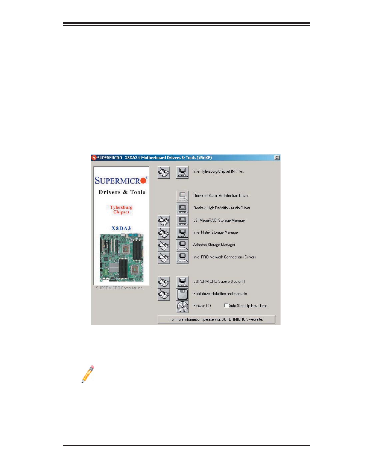
Appendix C: Software Installation Instructions
Appendix C
Software Installation Instructions
C-1 Installing Software Programs
After you've installed the Windows Operating System, a screen as shown below
will appear. You are ready to install software programs and drivers that have not
yet been installed. To install these software programs and drivers, click the icons
to the right of these items.
Note: Click the icons showing a hand writing on the paper to view the
readme fi les for each item. Click on a computer icon to the right of an item
to install an item (from top to the bottom) one at a time. After installing
each item, you must re-boot the system before proceeding with the next
item on the list. The bottom icon with a CD on it allows you to view the
entire contents of the CD.
Driver/Tool Installation Display Screen
C-1
Page 62
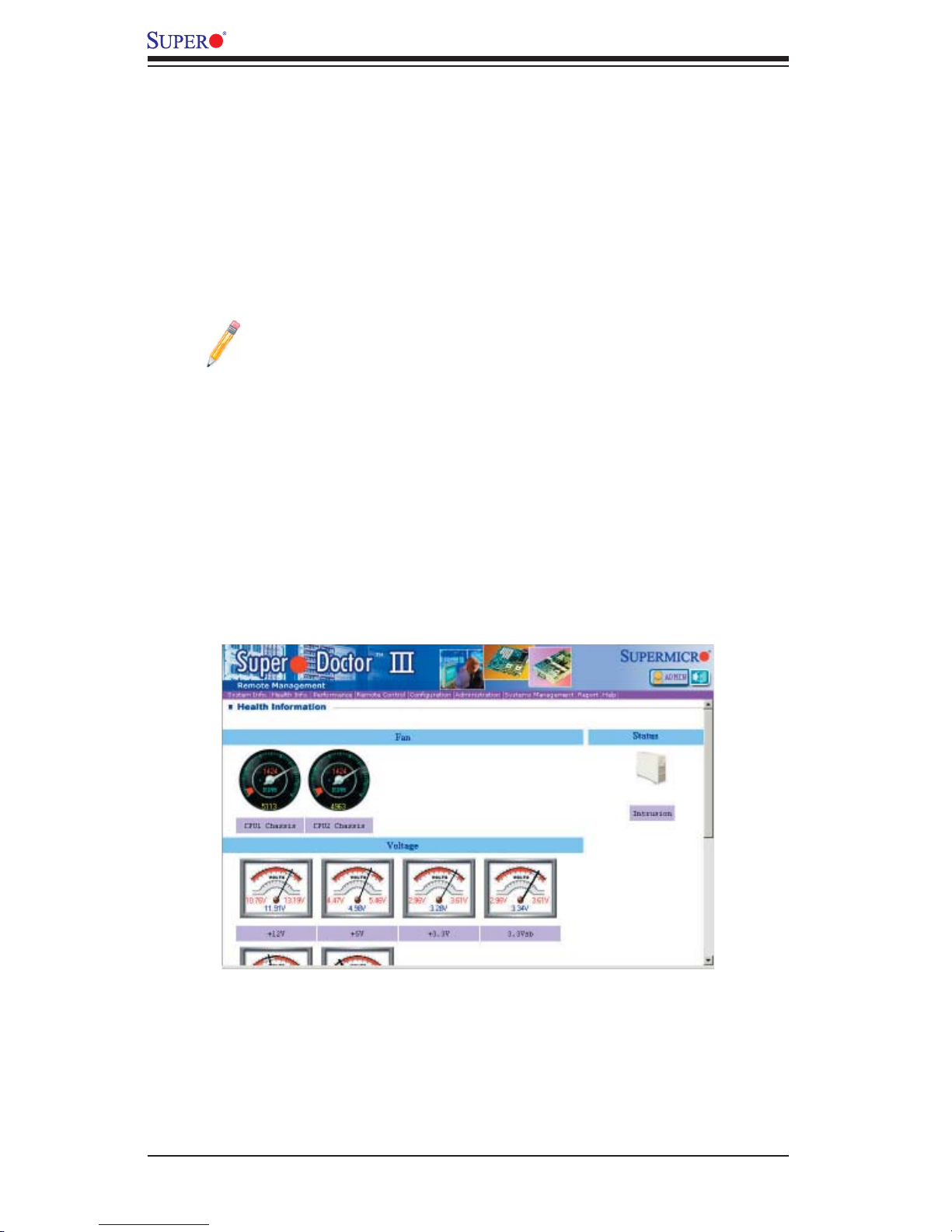
X8DA3/X8DAi User's Manual
C-2 Confi guring Supero Doctor III
The Supero Doctor III program is a Web-base management tool that supports
remote management capability. It includes Remote and Local Management tools.
The local management is called the SD III Client. The Supero Doctor III program
included on the CDROM that came with your motherboard allows you to monitor
the environment and operations of your system. Supero Doctor III displays crucial
system information such as CPU temperature, system voltages and fan status. See
the Figure below for a display of the Supero Doctor III interface.
Note: 1 The default user name and password are ADMIN.
Note 2: In the Windows OS environment, the Supero Doctor III settings
take precedence over the BIOS settings. When fi rst installed, Supero Doc-
tor III adopts the temperature threshold settings previously set in BIOS. Any
subsequent changes to these thresholds must be made within Supero Doc-
tor, since the SD III settings override the BIOS settings. For the Windows
OS to adopt the BIOS temperature threshold settings, please change the
SDIII settings to be the same as those set in BIOS.
Supero Doctor III Interface Display Screen-I (Health Information)
C-2
Page 63
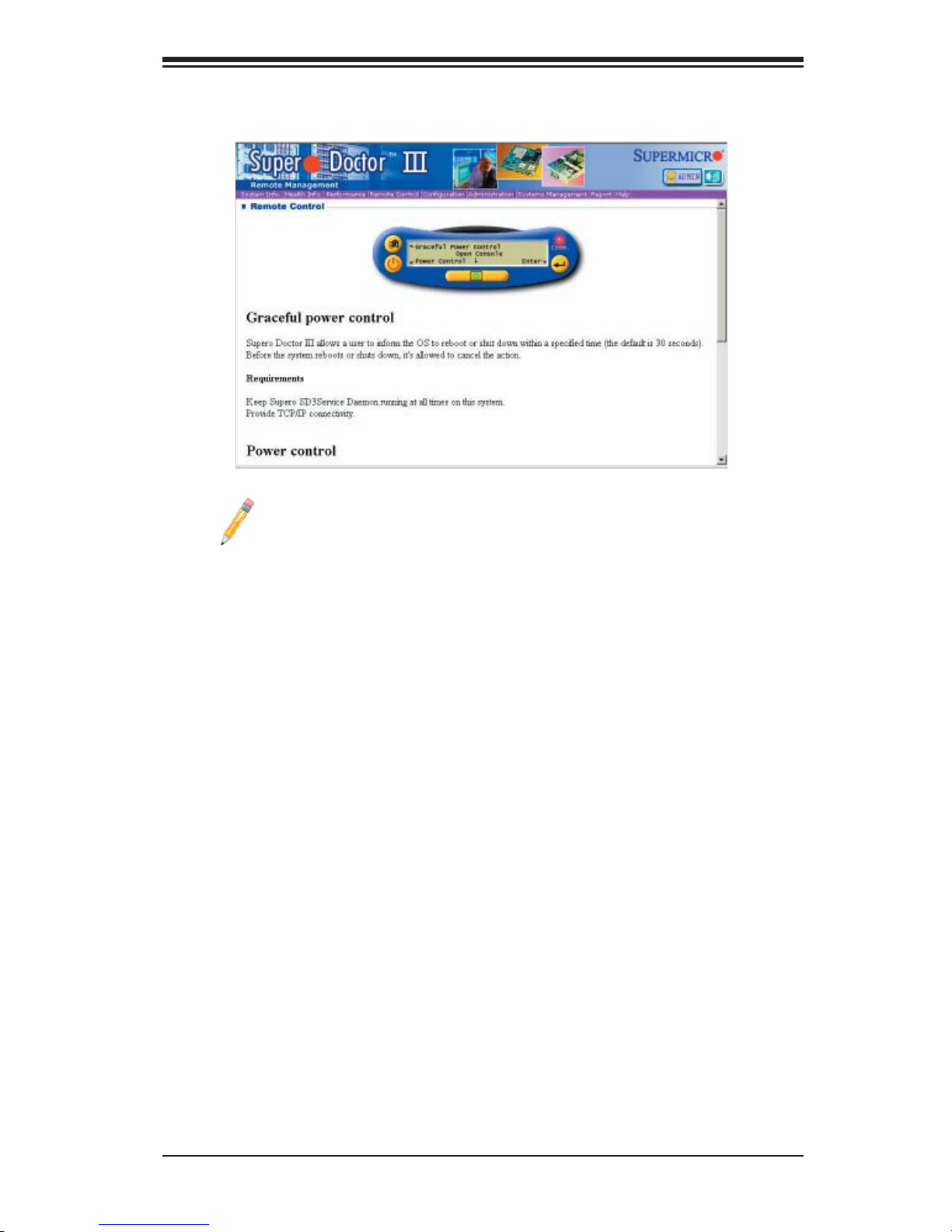
Appendix C: Software Installation Instructions
Supero Doctor III Interface Display Screen-II (Remote Control)
Note: SD III Software Revision 1.0 can be downloaded from our Web
site at: ftp://ftp.supermicro.com/utility/Supero_Doctor_III/. You can also
download SDIII User's Guide at: http://www.supermicro.com/PRODUCT/
Manuals/SDIII/UserGuide.pdf. For Linux, we will still recommend that you
use Supero Doctor II.
C-3
Page 64
X8DA3/X8DAi User's Manual
Notes
C-4
 Loading...