

Page 1
SUPER
SuperWorkstation
PIO-737A-i-MA015
®
USER’S MANUAL
1.0
Page 2

The information in this User’s Manual has been carefully reviewed and is believed to be accurate.
The vendor assumes no responsibility for any inaccuracies that may be contained in this document,
makes no commitment to update or to keep current the information in this manual, or to notify any
person or organization of the updates. Please Note: For the most up-to-date version of this
manual, please see our web site at www.supermicro.com.
Super Micro Computer, Inc. ("Supermicro") reserves the right to make changes to the product
described in this manual at any time and without notice. This product, including software and documentation, is the property of Supermicro and/or its licensors, and is supplied only under a license.
Any use or reproduction of this product is not allowed, except as expressly permitted by the terms
of said license.
IN NO EVENT WILL SUPERMICRO BE LIABLE FOR DIRECT, INDIRECT, SPECIAL, INCIDENTAL,
SPECULATIVE OR CONSEQUENTIAL DAMAGES ARISING FROM THE USE OR INABILITY TO
USE THIS PRODUCT OR DOCUMENTATION, EVEN IF ADVISED OF THE POSSIBILITY OF
SUCH DAMAGES. IN PARTICULAR, SUPERMICRO SHALL NOT HAVE LIABILITY FOR ANY
HARDWARE, SOFTW ARE, OR DA TA STORED OR USED WITH THE PRODUCT, INCLUDING THE
COSTS OF REPAIRING, REPLACING, INTEGRATING, INSTALLING OR RECOVERING SUCH
HARDWARE, SOFTWARE, OR DATA.
Any disputes arising between manufacturer and customer shall be governed by the laws of Santa
Clara County in the State of California, USA. The State of California, County of Santa Clara shall
be the exclusive venue for the resolution of any such disputes. Super Micro's total liability for all
claims will not exceed the price paid for the hardware product.
FCC Statement: This equipment has been tested and found to comply with the limits for a class B
digital device, pursuant to Part 15 of the FCC Rules. These limits are designed to provide reasonable
protection against harmful interference in a residential installation. This equipment generates, uses,
and can radiate radio frequency energy and, if not installed and used in accordance with the instructions, may cause harmful interference to radio communications. However, there is no guarantee that
interference will not occur in a particular installation. If this equipment does cause harmful interference to radio or television reception, which can be determined by turning the equipment off and on,
the user is encouraged to try to correct the interference by one or more of the following measures:
• Reorient or relocate the receiving antenna.
• Increase the separation between the equipment and receiver.
• Connect the equipment to an outlet on a circuit different from that to which the receiver
is connected.
• Consult the authorized dealer or an experienced radio/TV technician for help.
California Best Management Practices Regulations for Perchlorate Materials: This Perchlorate warning applies only to products containing CR (Manganese Dioxide) Lithium coin cells. “Perchlorate
Material-special handling may apply. See www.dtsc.ca.gov/hazardouswaste/perchlorate”
WARNING: Handling of lead solder materials used in this
product may expose you to lead, a chemical known to the
State of California to cause birth defects and other reproductive harm.
Manual Revision 1.0
Release Date: October 31, 2012
Unless you request and receive written permission from Super Micro Computer, Inc., you may not
copy any part of this document.
Information in this document is subject to change without notice. Other products and companies
referred to herein are trademarks or registered trademarks of their respective companies or mark
holders.
Copyright © 2012 by Super Micro Computer, Inc.
All rights reserved.
Printed in the United States of America
Page 3

Preface
About This Manual
This manual is written for professional system integrators and PC technicians.
It provides information for the installation and use of the SuperWorkstation PIO737A-i-MA015. Installation and maintenance should be performed by experienced
technicians only.
Manual Organization
Chapter 1: Workstation Overview
Preface
The fi rst chapter provides a list of the main components included with the system
and describes the main features.
Chapter 2: Server Setup
This chapter describes the steps necessary to set up the SuperWorkstation
5037A-i2-MA015. A motherboard layout is included and jumper settings are described here.
Chapter 3: Component Installation
Refer here for details on installing components to the system, including CPUs,
memory and power supplies.
Appendix A: Software
Appendix B: BIOS Beep Codes
Appendix C: System Specifi cations
iii
Page 4

SuperWorkstation PIO-737A-i-MA015 User's Manual
Table of Contents
Chapter 1 Workstation Overview
1-1 Introduction ......................................................................................................1-1
System Recovery Instructions.........................................................................1-1
1-2 Motherboard Features ..................................................................................... 1-2
Processors ......................................................................................................1-2
Memory ...........................................................................................................1-2
SATA ..............................................................................................................1-2
PCI Expansion Slots ....................................................................................... 1-2
Onboard Controllers/Ports ..............................................................................1-2
1-3 Chassis Features ............................................................................................1-3
System Power ................................................................................................. 1-3
SATA Support .................................................................................................. 1-3
Front Control Panel .........................................................................................1-3
Cooling System ............................................................................................... 1-3
Control Panel .................................................................................................. 1-3
1-4 Contacting Supermicro .................................................................................... 1-6
Chapter 2 Workstation Setup
2-1 Unpacking the System .................................................................................... 2-1
2-2 Preparing for Setup .........................................................................................2-1
2-3 Motherboard Layout ........................................................................................2-2
2-4 Jumper Settings ..............................................................................................2-4
2-5 Onboard Indicators .......................................................................................... 2-7
2-6 SATA Ports ......................................................................................................2-7
Chapter 3 Component Installation
3-1 Removing Power .............................................................................................3-1
3-2 Accessing the System ..................................................................................... 3-1
3-3 Adding PCI Add-On Cards .............................................................................. 3-2
3-4 Installing a CPU and Heat Sink ......................................................................3-3
Installing an LGA 2011 Processor ................................................................... 3-3
Installing a CPU Heat Sink ............................................................................. 3-6
Removing the Heat Sink .................................................................................3-7
3-5 Installing Memory Modules ............................................................................. 3-8
3-6 System Fan ................................................................................................... 3-12
3-7 Hard Drive Installation ................................................................................... 3-13
Installing Components in the 5.25" Drive Bays ............................................ 3-15
vi
Page 5

Table of Contents
3-8 Power Supply ................................................................................................ 3-16
3-9 Motherboard Battery ..................................................................................... 3-17
Appendix A Software
A-1 Operating System ...........................................................................................A-1
System Recovery Instructions......................................................................... A-1
Support ............................................................................................................A-1
A-2 Installing Drivers ..............................................................................................A-2
A-3 SuperDoctor III ................................................................................................A-3
A-4 BIOS ................................................................................................................A-4
Starting BIOS Setup Utility ..............................................................................A-4
How To Change the Confi guration Data .........................................................A-5
How to Start the Setup Utility ......................................................................... A-5
Appendix B BIOS Beep Codes
Appendix C System Specifi cations
vii
Page 6

SuperWorkstation PIO-737A-i-MA015 User's Manual
Notes
viii
Page 7
Chapter 1: Workstation Overview
Chapter 1
Workstation Overview
1-1 Introduction
The PIO-737A-i-MA015 is a high-end turnkey workstation. A replacement parts list
is shown below. A complete list of safety warnings is provided on the Supermicro
web site at http://www.supermicro.com/about/policies/safety_information.cfm
Replacement Parts List
Qty. Defi nition Part Number
1 Black SC733 Mid Tower Chassis w/ 665W Power Supply CSE-733TQ-665BP
1 Black Lite-On 5.25" HH 24x DVD-RW SATA Drive DVM-LITE-DVDRW24-HBT
5 61-cm SATA Cables CBL-0044L
1 12-cm Chassis Fan FAN-0124L4
2 Sandy Bridge 4C E5-1620 3.6G 10M 130W 2011 Processor P4X-DPE52630-SR0KV
1 Motherboard X9DAi
4 4GB DDR3-1600 1.5V 2Rx8 LP ECC REG DIMMs MEM-DR340L-SL02-ER16
1 Seagate 1.0 TB 6Gb/s 7.2k RPM, 3.5" SATA 3.0 HDD HDD-T1000-ST1000NM0011
2 2U Active CPU Heat Sink for X9 Socket R SNK-P0048AP4
1 NVIDIA® Quadro 4000 AOC-GPU-NVQ4000
1 Standard I/O Shield for X9DA6 with EMI Gasket MCP-260-00045-0N
System Recovery Instructions
This computer includes a hidden partition which contains a backup of your factory
Windows installation. In case of a system failure, you can use this backup to restore
your computer to a working state in just a few minutes.
Since this backup resides on the same physical hard-disk as your current Windows
installation, a hardware failure of the hard-disk will prevent you from reinstalling
Windows. There are two different ways to initiate a system recovery of your system:
• Trigger recovery from OS level (run FullRestore.exe)
• Trigger recovery during system boot up (press F10 key).
Warning: System Recovery will wipe all of your personal data and restore the system
to OOBE. You must have your CD-KEY from COA label ready before performing this
action. System Recovery is an automated, one-step process. Do not initiate a system
recovery unless you are prepared for a complete re-installation back to the factory
default installation.
1-1
Page 8

SuperWorkstation PIO-737A-i-MA015 User's Manual
1-2 Motherboard Features
The SuperWorkstation PIO-737A-i-MA015 uses the X9DAi, a dual processor motherboard built around the Intel® C600 series chipset. Below are the main features
of the X9DAi.
Processors
The PIO-737A-i-MA015 supports single or dual Intel E5-2600 processors in LGA
2011 sockets. Please refer to the motherboard description pages on our Web site
for a complete listing of supported processors (www.supermicro.com).
Memory
The PIO-737A-i-MA015 features up to 512 GB of registered/unbuffered ECC DDR31333/1066/800 LRDIMMs (load-reduced DIMMs).
SATA
A SATA controller is integrated into the chipset to provide a Serial ATA subsystem.
The PIO-737A-i-MA015 supports six SATA 3.0 and four SATA 2.0 ports.
PCI Expansion Slots
The PIO-737A-i-MA015 features the following PCI expansion slots:
Three PCI-Express 3.0 x16, two PCI-Express 3.0 x8 and one PCI-Express 3.0 x4
slots.
Onboard Controllers/Ports
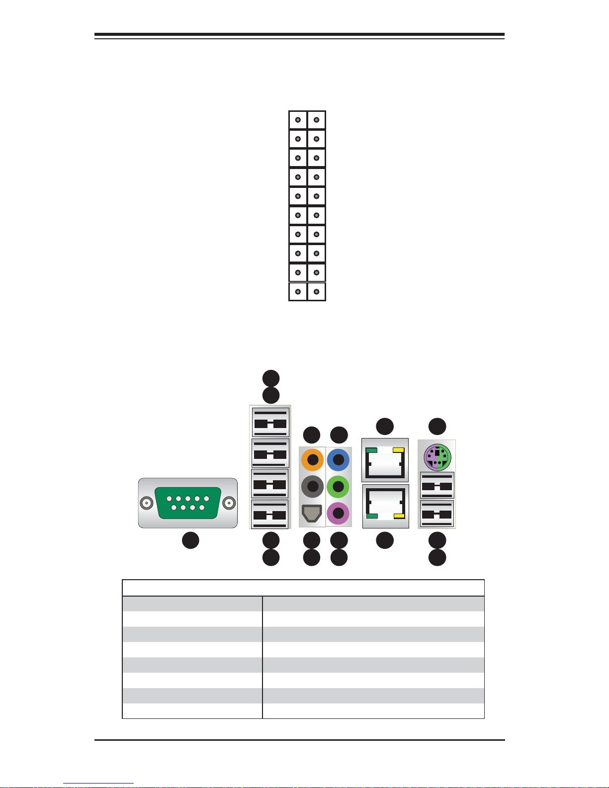
The color-coded I/O ports include one COM port, six USB 2.0 ports, PS/2 mouse
and keyboard ports, two Gb Ethernet ports and six HDA (High Defi nition Audio)
ports. See Figure 1-2.
1-2
Page 9

Chapter 1: Workstation Overview
1-3 Chassis Features
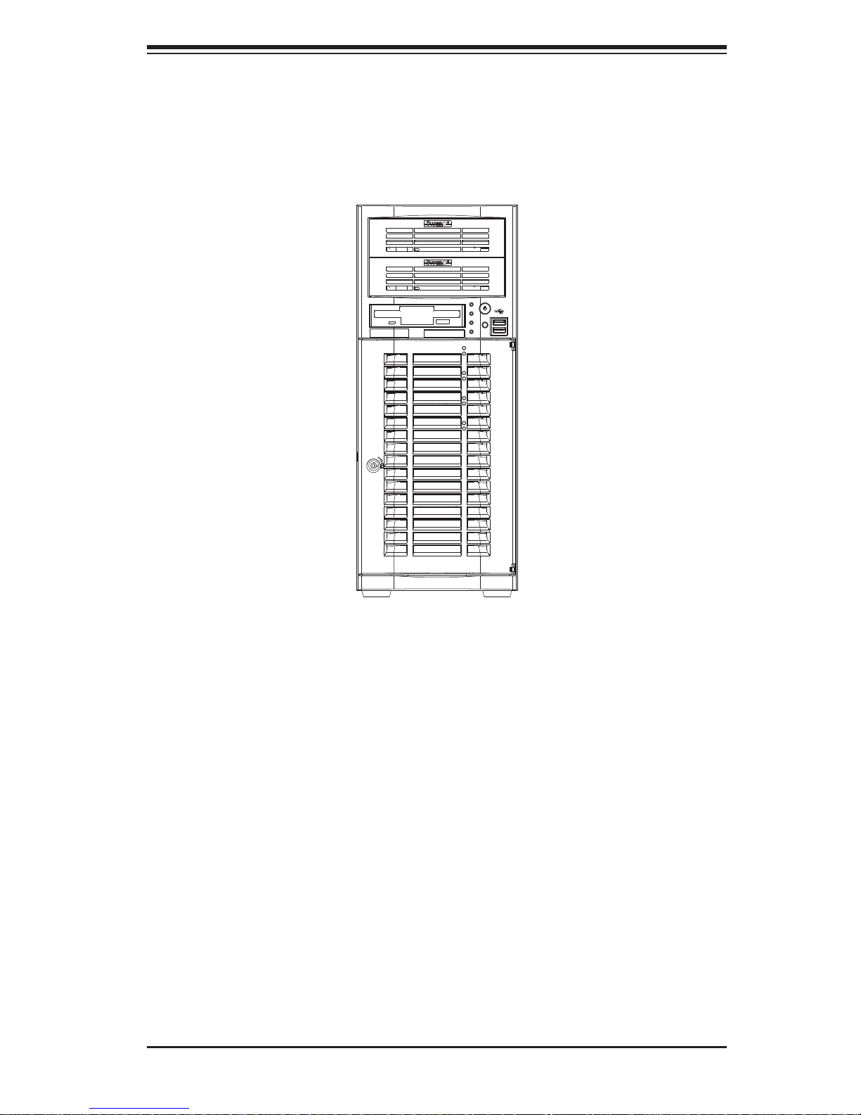
The PIO-737A-i-MA015 is a workstation. The following is a general outline of the
main features of the enclosure. See Figure 1-3 for a front view.
System Power
The PIO-737A-i-MA015 features a low-noise, high-effi ciency 665W power supply.
Power must be removed from the system before servicing or replacing the power
supply.
SATA Support
The PIO-737A-i-MA015 was designed to support four 3.5" SATA hard drives, which
are hot- swappa ble unit s.
Front Control Panel
The control panel on the PIO -737A-i -M A015 provides you with system monitoring
and control. LEDs indicate power on, network activity, hard disk drive activity and
overheat conditions. The control panel also includes a main power button and a
system reset button.
Cooling System
The PIO-737A-i-MA015 has an innovative cooling design that provides suffi cient
cooling at very low noise level - ideal for a workplace environment. The chassis
includes one 12-cm exhaust fan located at the front of the system.
Control Panel
JF1 contains header pins for various front control panel connectors. See Figure 1-1
for the pin locations of the various front control panel buttons and LED indicators.
1-3
Page 10
SuperWorkstation PIO-737A-i-MA015 User's Manual
Figure 1-1. Control Panel Header Pins
20 19
Ground
NMI
x (Key)
Power On LED
HDD LED
NIC1 LED
NIC2 LED
OH/Fan Fail LED
Power Fail LED
Ground
Ground
Figure 1-2. I/O Ports
5
4
x (Key)
Vcc
Vcc
Vcc
Vcc
Vcc
Vcc
Reset (Button)
Power (Button)
2 1
13
11
8
1
1
3
2
10
7
1
6
9
1
12
1
16
1
15
1
14
1
I/O Backpanel
1. COM1 Port (Turquoise) 9. MIC In
2. USB 2.0 Port 0 10. Line Out
3. USB 2.0 Port 1 11. Line In
4. USB 2.0 Port 2 12. Gb LAN 1 Port
5. USB 2.0 Port 2 13. CGb LAN 2 Port
6. SPDIF Out 14. USB 3.0 Port 0 (or USB keyboard/mouse)
7. Surround Out 15. USB 3.0 Port 1 (or USB keyboard/mouse)
8. CEN/LFE Out 16. PS/2 Keyboard or Mouse
1-4
Page 11
Chapter 1: Workstation Overview
Figure 1-3. Front View of Workstation
1-5
Page 12

SuperWorkstation PIO-737A-i-MA015 User's Manual
1-4 Contacting Supermicro
Headquarters
Address: Super Micro Computer, Inc.
980 Rock Ave.
San Jose, CA 95131 U.S.A.
Tel: +1 (408) 503-8000
Fax: +1 (408) 503-8008
Email: [email protected] (General Information)
[email protected] (Technical Support)
Web Site: www.supermicro.com
Europe
Address: Super Micro Computer B.V.
Het Sterrenbeeld 28, 5215 ML
's-Hertogenbosch, The Netherlands
Tel: +31 (0) 73-6400390
Fax: +31 (0) 73-6416525
Email: [email protected] (General Information)
[email protected] (Technical Support)
[email protected] (Customer Support)
Asia-Pacifi c
Address: Super Micro Computer, Inc.
4F, No. 232-1, Liancheng Rd
New Taipei City 235
Taiwan
Tel: +886-(2) 8226-3990
Fax: +886-(2) 8226-3991
Web Site: www.supermicro.com.tw
Technical Support:
Email: [email protected]
Tel: +886-(2)-8226-3990
1-6
Page 13

Chapter 2: Workstation Setup
Chapter 2
Workstation Setup
2-1 Unpacking the System
You should inspect the box the system was shipped in and note if it was damaged
in any way. If the system itself shows damage you should fi le a damage claim with
the carrier who delivered it.
Review the warnings and cautions, which may also be found on the Supermicro
Web site at http://www.supermicro.com/about/policies/safety_information.cfm.
2-2 Preparing for Setup
Decide on a suitable location for the workstation. It should be situated in a clean,
dust-free area that is well ventilated. Avoid areas where heat, electrical noise and
electromagnetic fi elds are generated. You will also need it placed near a grounded
AC power outlet.
Setting Up
1. Locate the workstation is a suitable area according to the guidelines above.
2. Connect the mouse, keyboard and monitor to the workstation.
3. Connect an Ethernet cable to a LAN port if needed.
4. Connect the power to the power supply and then to a grounded AC outlet.
2-1
Page 14
SuperWorkstation PIO-737A-i-MA015 User's Manual
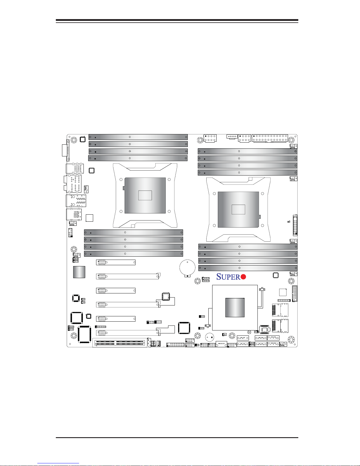
2-3 Motherboard Layout
This section provides details on the motherboard and jumper settings that may be
useful when setting up the system.
Figure 2-1. Layout
COM1
USB2.0
0/1/2/3
7.1 Audio
LAN1/2
USB3.0
0/1
FP Audio
Header
J18
Audio
CTRL
CPLD
JP29
JP30
FAN5
FAN4
JPL2
JPL1
GLAN
CTRL
JSPDIF_Out
JSPDIF_In
FAN7
(CPU2 Fan)
KB/MS
PS2
CPU2 Slot6 PCI-E 3.0 x8
CPU2 Slot5 PCI-E 3.0 x16
CPU2 Slot4 PCI-E 3.0 x8
CPU1 Slot3 PCI-E 3.0 x16
CPU1 Slot2 PCI-E 3.0 x4 in x8
J21
CPU1 Slot1 PCI-E 3.0 x16
S I/O
(SIMBMC Slot)
JIPMI1
P2 DIMMG1
P2 DIMMG2
P2 DIMMH1
P2 DIMMH2
CPU2
P2 DIMMF2
P2 DIMMF1
P2 DIMME2
P2 DIMME1
Always Populate DIMMxA First
JI2C2
JI2C1
JBR1
JPME1
JIPMB1
CLK Buffer
JI2C2
TPM/Port80
JRK1
JTPM1
Battery
1394a
CTRL
BT1
CNF2
CNF1
JWD1
STBY1
JL1
T-SGPIO2
JPWR1
JPP0
JPP1
USB4
SP1
T-SGPIO1
JSD1
JPI2C1
Intel
C600-A
USB5/6
JPWR2
P1 DIMMA1
P1 DIMMA2
P1 DIMMB1
P1 DIMMB2
CPU1
P1 DIMMD2
P1 DIMMD1
P1 DIMMC2
P1 DIMMC1
I-SATA5
I-SATA4
X9DAi
1.02
Rev.
JBT1
I-SATA3
JWP1
I-SATA2
JPI1
JOH1
J22
BIOS
USB 3.0
CTRL
I-SATA1
I-SATA0
FAN1
FAN6
(CPU1Fan)
LE1
FAN2
FAN3
JD1
FANA
JF1
SAS0~3
USB3.0 2/3
SAS4~7
2-2
Page 15

Chapter 2: Workstation Setup
Motherboard Headers/Connectors
Jumper Description Default Setting
JBT1 Clear CMOS See Section 5-10
JP4 SMBus En/Disable Pins 1-2 (Enabled)
JPI1 IEEE1394a En/Disable Pins 1-2 (Enabled)
JPL1/2 GLAN1/GLAN2 En/Disable Pins 1-2 (Enabled)
JPME1 ME Recovery Pins 2-3 (Normal)
JPP0 JTAG Scan Pins 2-3 (CPU 1 only)
JPP1 JTAG Scan Pins 2-3 (CPU 2 only)
JWD Watch Dog Pins 1-2 (Reset)
JWP1 Write Protect Enable Pins 1-2 (Enabled)
Connector Description
7.1 Audio 8 Channel (7.1) High-Defi nition Backplane Audio Connector
BT1 Onboard Battery
CNF1/CNF2 IEEE 1394a 1/2 Connectors
COM1 Backplane COM Port1
FAN1~7, FANA CPU/System Fan Headers (Fan6/Fan7: CPU 1/2 Fans)
I-SA T A 0~5 Intel SATA Ports 0~5 (SA TA 0/1 = SATA3, SATA2~5 = SATA 2)
J18 Audio Header
J22 ATX 24-Pin Power Connector
JD1 Speaker/Power LED Indicator
JF1 Front Panel Control Header
2
JI
C1 Power Supply SMBbus I2C Header
JL1 Chassis Intrusion
JIPMI1 SIM_BMC Slot
JIPMB 4-pin External BMC I
2
C Header (for an IPMI Card)
JPWR1/JPWR2 12V 8-Pin Power Connectors
JRK1 Option ROM Upgrade for the chipset
JSPDIF_In SPDIF (Sony/Philips Digital Interface) In Header
2-3
Page 16
SuperWorkstation PIO-737A-i-MA015 User's Manual
2-4 Jumper Settings
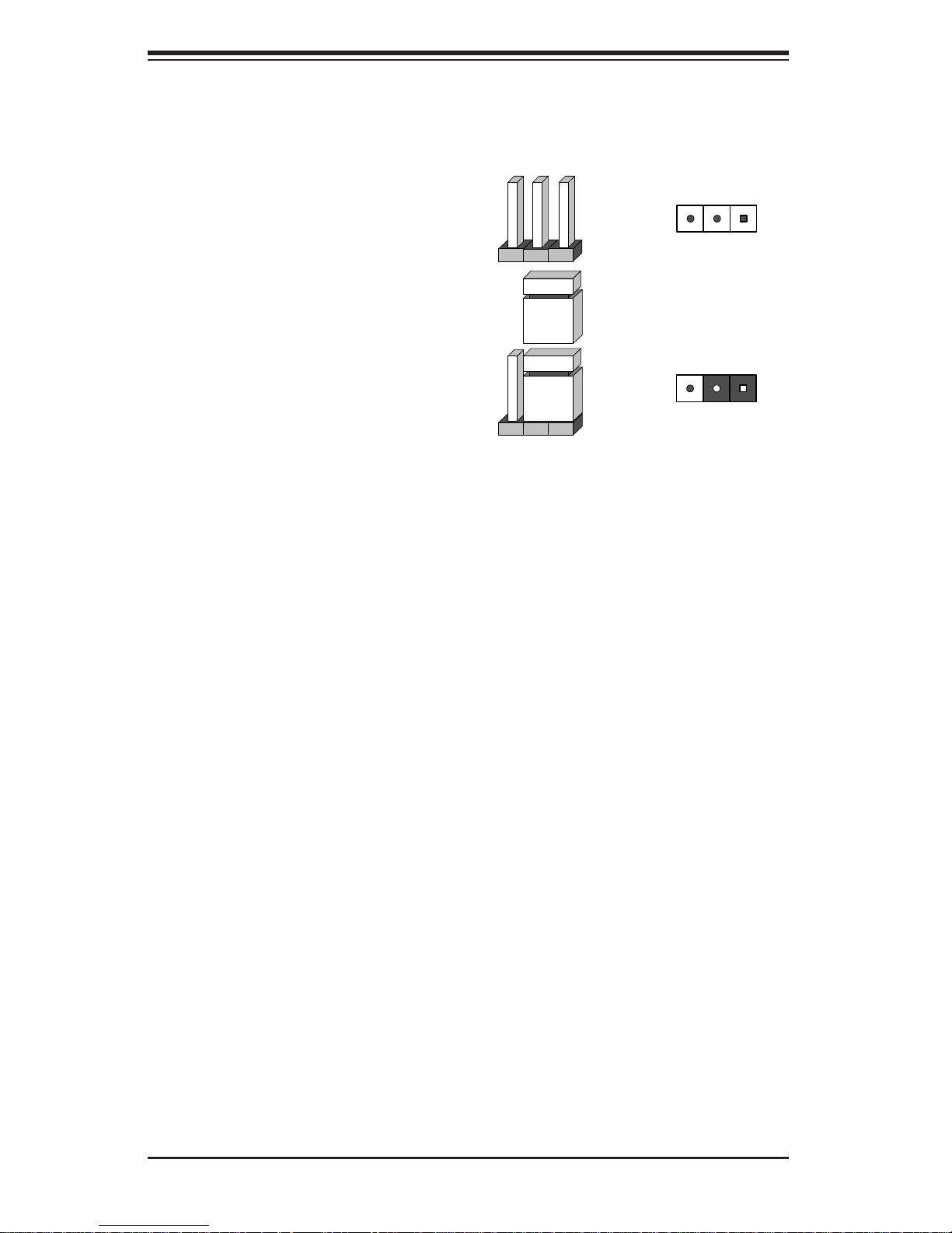
Explanation of Jumpers
To modify the operation of the motherboard, jumpers can be used to choose
between optional settings. Jumpers
create shorts between two pins to
change the function of the connector.
Pin 1 is identifi ed with a square solder
pad on the printed circuit board. See
the motherboard layout pages for
jumper locations.
Note: On a two-pin jumper, "Closed"
means the jumper is on both pins and
"Open" means the jumper is either on
only one pin or completely removed.
3 2 1
Connector
Pins
Jumper
3 2 1
Setting
Clear CMOS (JBT1)
JBT1 is used to clear CMOS. Instead of pins, this "jumper" consists of contact pads
to prevent accidental clearing of CMOS. To clear CMOS, use a metal object such
as a small screwdriver to touch both pads at the same time to short the connection. Always remove the AC power cord from the system before clearing CMOS.
Note: For an ATX power supply, you must completely shut down the system, remove
the AC power cord and then short JBT1 to clear CMOS.
2-4
Page 17
GLAN Enable/Disable
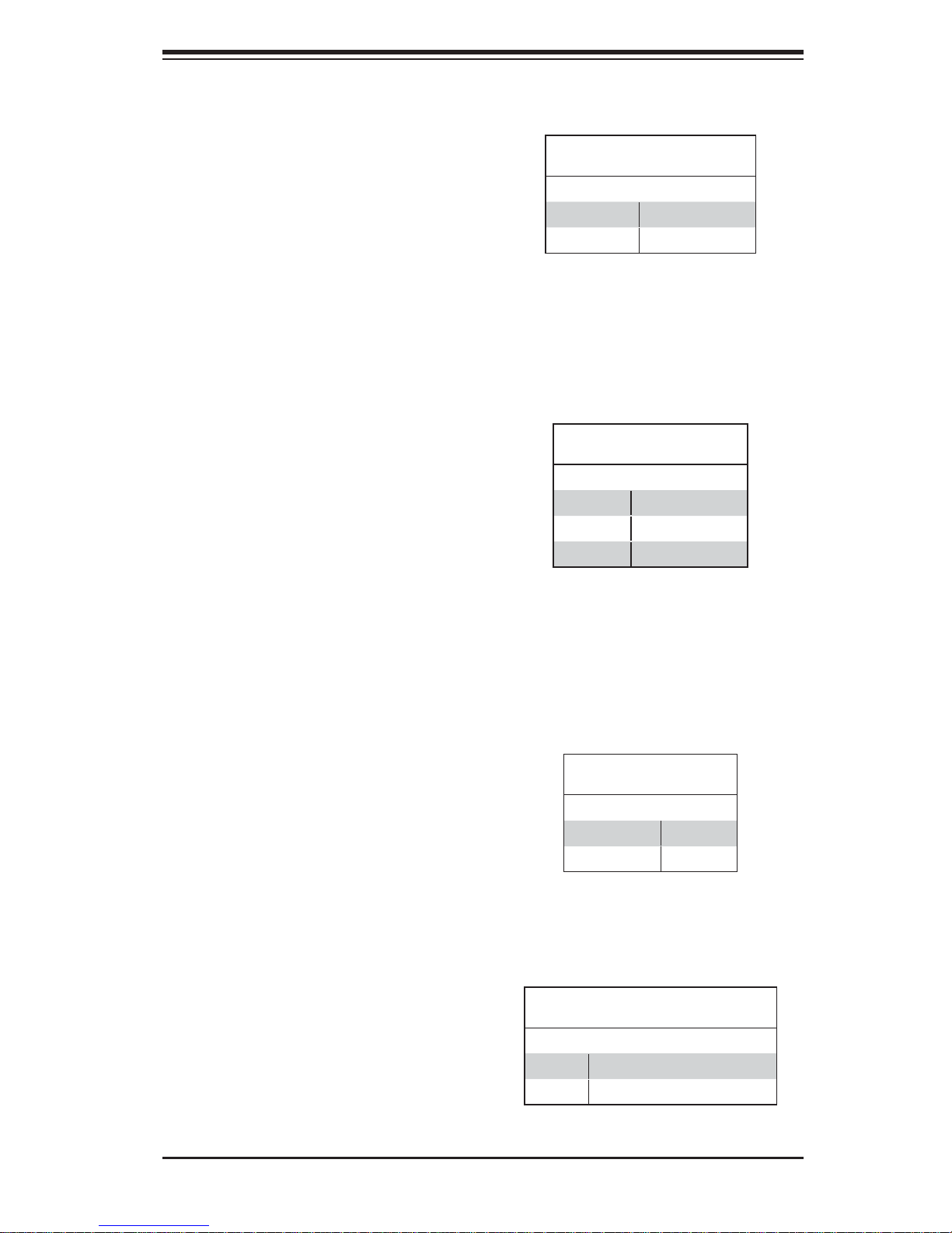
Change the setting of jumper JPL1 or
JPL2 to enable or disable the LAN1
and LAN2 Ethernet ports, respectively.
See the table on the right for jumper
settings. The default setting is enabled.
Watch Dog Enable/Disable
JWD controls the Watch Dog function.
Watch Dog is a system monitor that
can reboot the system when a software
application hangs. Jumping pins 1-2
will cause WD to reset the system if
an application hangs. Jumping pins 2-3
will generate a non-maskable interrupt
signal for the application that hangs.
See the table on the right for jumper
settings. Watch Dog must also be
enabled in BIOS.
Chapter 2: Workstation Setup
GLAN
Jumper Settings
Jumper Setting Defi nition
1-2 Enabled (default)
2-3 Disabled
Watch Dog
Jumper Settings
Jumper Setting Defi nition
Pins 1-2 Reset (default)
Pins 2-3 NMI
Open Disabled
IEEE 1394a Enable/Disable
JPI1 allows you to enable or disable
the onboard IEEE 1394a (Firewire)
support. The default position is on pins
1 and 2 to use the 1394_1 and 1394_2
connections. See the table on the right
for jumper settings.
Write Protect Enable/Disable
Close pins 1/2 of jumper JWP1 to enable write protect support for system
security and data integrity. See the
table on the right for jumper settings.
2-5
1394a
Jumper Settings
Both Jumpers Defi nition
Pins 1-2 Enabled
Pins 2-3 Disabled
WriteProtect
Jumper Settings
Jumper Setting Defi nition
Pins 1/2 Write_Protect Enable (Default)
Pins 2/3 Write_Protect Disable
Page 18
SuperWorkstation PIO-737A-i-MA015 User's Manual
Manufacture Mode
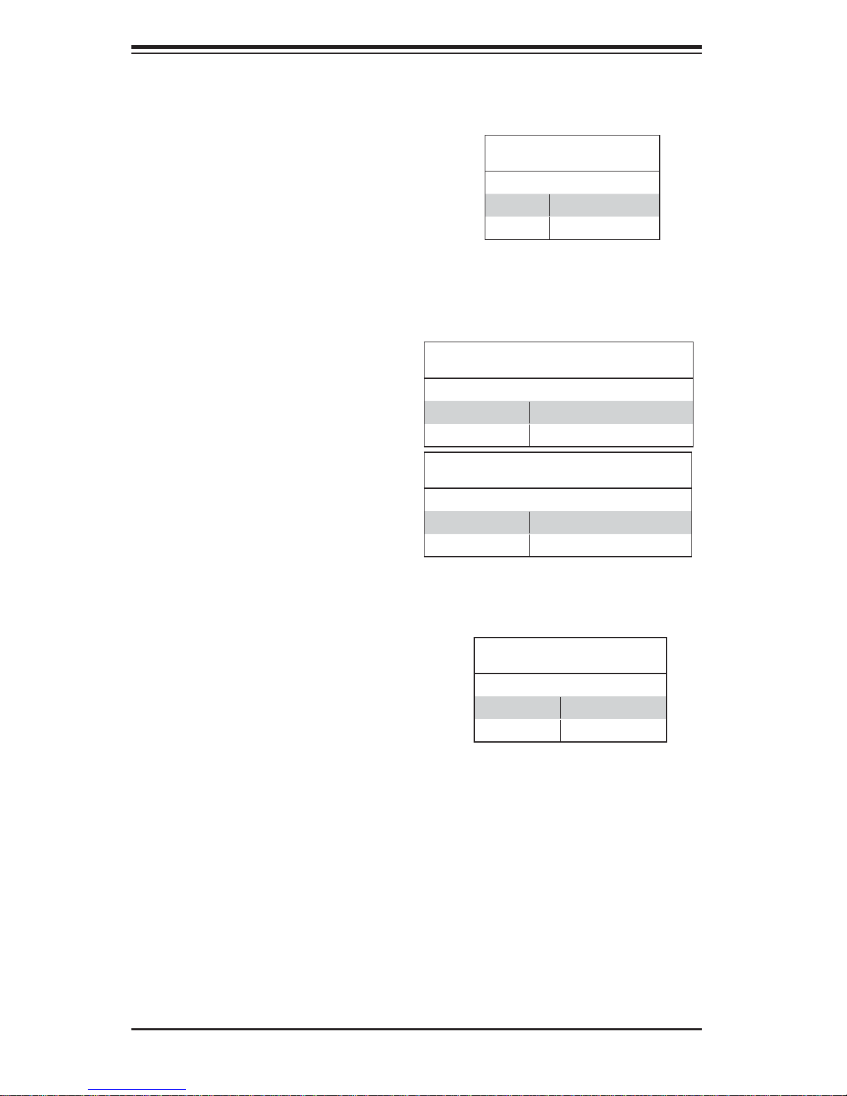
Jumper JPME1 allows the user to
fl ash the system fi rmware from a host
server to modify system settings.
Close this jumper to bypass SPI fl ash
security, and force ME into recovery
mode in order to use recovery jumpers. See the table on the right for
jumper settings.
JTAG Scan
The JT AG scan jumpers (JPP0/JPP1)
allow the user to configure JTAG
scan settings for system debugging.
See the table on the right for jumper
settings.
Jumper Setting Defi nition
Pins 1/2, 3/4 including CPU2 in JTAG Scan
Pins 2/3 (Default) JTAG Scan: CPU1 only
Jumper Setting Defi nition
Pins 1/2, 3/4 including CPU1 in JTAG Scan
Pins 2/3 (Default) JTAG Scan: CPU2 only
ME Mode Select
Jumper Settings
Jumper Setting Defi nition
Pins 1-2 Manufacture Mode
Pins 2-3 Normal (Default)
JTAG Scan (JPP0)
Jumper Settings
JTAG Scan (JPP1)
Jumper Settings
SMB Enable/Disable
Jumper JP4 allows the user to enable
System Management Bus support. The
default setting is 1-2 to enable support.
See the table on the right for jumper
settings.
SMB
Jumper Settings
Jumper Setting Defi nition
1-2 Enabled (Default)
2-3 Disabled
2-6
Page 19
2-5 Onboard Indicators
LAN1/2 LEDs
The Ethernet ports (located beside
the VGA port) have two LEDs. On
each port, one LED indicates activity
while the other LED may be green,
amber or off to indicate the speed of
the connection. See the table on the
right for the functions associated with
the connection speed LED.
Chapter 2: Workstation Setup
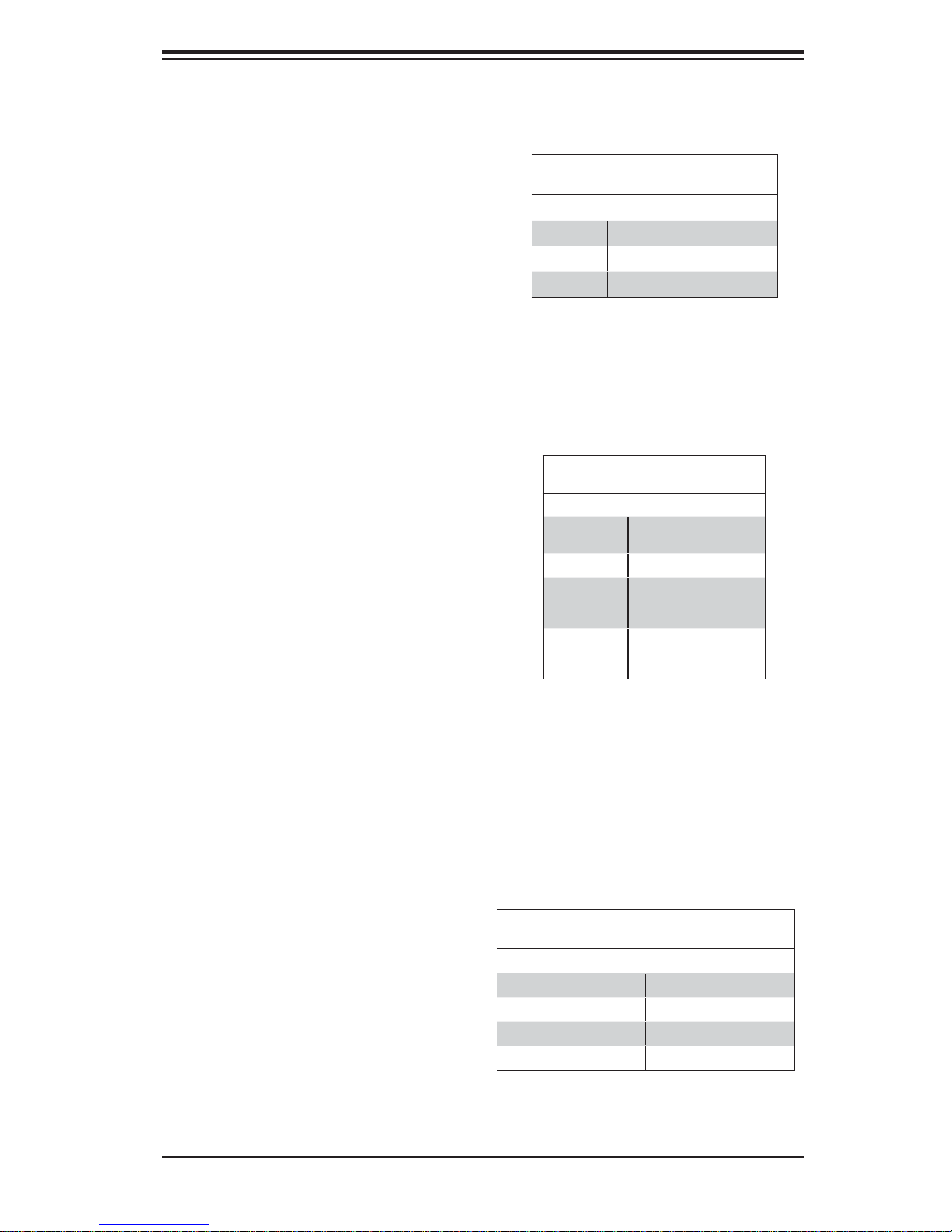
LAN1/2 LED
(Connection Speed Indicator)
LED Color Defi nition
Off No Connection or 10 Mb/s
Green 100 Mb/s
Amber 1 Gb/s
Onboard Power LED
An Onboard Power LED is located at
LE1 on the serverboard. When this
LED is on, the system is on. Be sure
to turn off the system and unplug the
power cord before removing or installing components. See the table at right
for more information.
2-6 SATA Ports
SATA Ports
Onboard PWR LED Indicator (LE1)
LED Color Status
Off System Off (PWR cable
Green System On
Green:
Flashing
Quickly
Green:
Flashing
Slowly
LED Defi nitions
not connected)
ACPI S1 State
ACPI S3 (STR) State
Two SATA3 Ports (I-SATA0/1), colored in white, and four SATA2 Ports
(I-SATA2~5) are located on the
serverboard. These ports provide
serial-link signal connections, which
are faster than the connections of
Parallel ATA. See the table on the right
for pin de fi nitions.
SATA Port
Pin Defi nitions
Pin# Defi nition Pin # Defi nition
1 Ground 2 TXP
3 TXN 4 Ground
5 RXN 6 RXP
7 Ground
2-7
Page 20

SuperWorkstation PIO-737A-i-MA015 User's Manual
Notes
2-8
Page 21

Chapter 3: Component Installation
Chapter 3
Component Installation
Several steps must be taken prior to installing components in the system. Installation
or replacement of most components require that power fi rst be removed from the
system. Please follow the procedures given for each type of component.
3-1 Removing Power
Use the following procedure to ensure that power has been removed disconnected
from the system.
1. Use the operating system to power down the system.
2. After the system has completely shut-down, carefully grasp the head of the
power cord and gently pull it out of the back of the power supply.
3. Disconnect the cord from the power strip or wall outlet.
3-2 Accessing the System
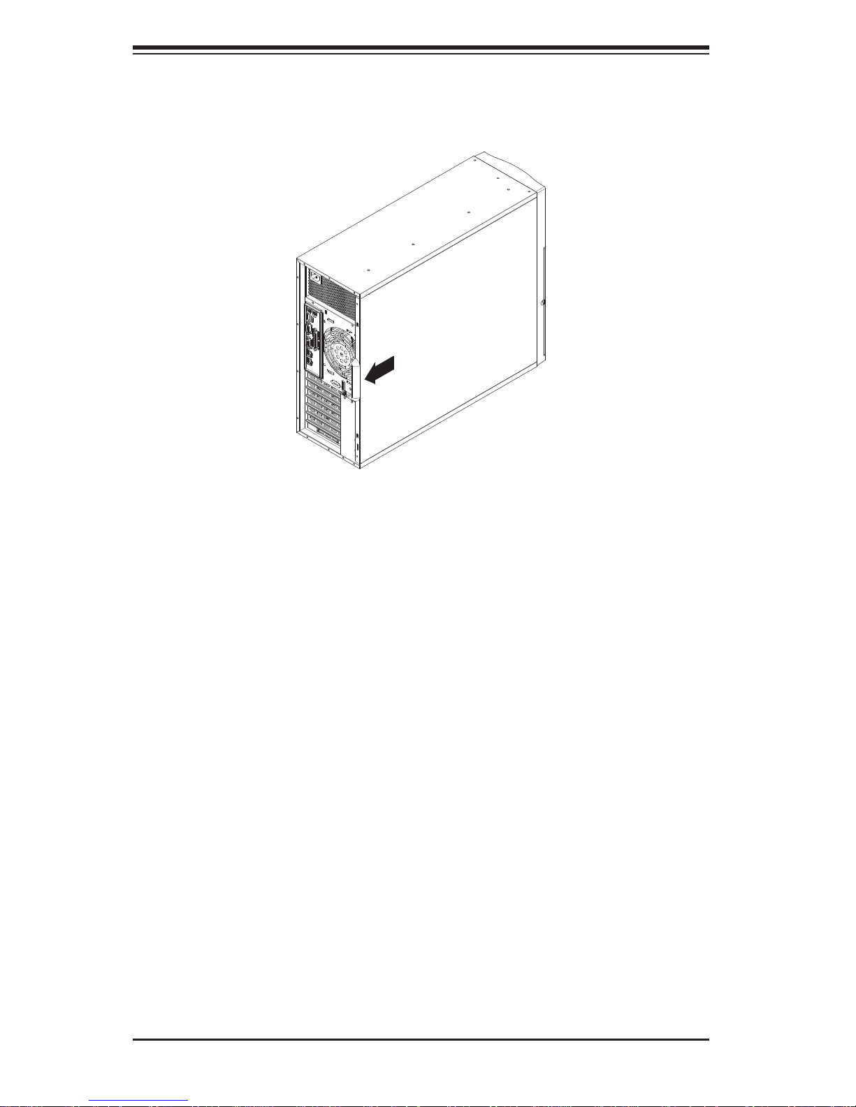
The PIO-737A-i-MA015 features a removable side cover, allowing easy access to
the system interior.
Removing the Side Cover
1. Begin by removing the two screws from the back lip of the side cover (this is
the left cover when looking at the chassis from the front.)
2. Grab the handle and gently pull the side cover out to release it from its position.
3. Once the side cover is out of its position, slide the cover out of the chassis.
Caution: Except for short periods of time, do NOT operate the system without the
cover in place. The chassis cover must be in place to allow for proper airfl ow and
to prevent overheating.
Additional warnings and cautions can be found on the Supermicro Web site at http://
www.supermicro.com/about/policies/safety_information.cfm.
3-1
Page 22
SuperWorkstation PIO-737A-i-MA015 User's Manual
Figure 3-1. Removing the Chassis Side Covers
3-3 Adding PCI Add-On Cards
The PIO-737A-i-MA015 can accommodate standard size add-on cards populated
in all slots.
Installing an Add-on Card
1. Begin by removing power from the system as described on page 3-1.
2. Removethe PCI slot shield for the slot you wish to populate.
3. Fully seat the card into the card slot, pushing down with your thumbs evenly
on both sides of the card.
4. Finish by using a screw to secure the top of the card shield to the chassis.
The PCI slot shields protect the motherboard and its components from EMI
and aid in proper ventilation, so make sure there is always a shield covering
each unused slot.
3-2
Page 23
Chapter 3: Component Installation
OPEN 1st
WARNING!
OPEN 1st
WARNING!
3-4 Installing a CPU and Heat Sink
Caution: When handling the processor package, avoid placing direct pressure on
the label area of the fan.
Preparation
1. Begin by removing power from the system as described on page 3-1. Always
connect the power cord last and always remove it before adding, removing or
changing the CPU. Install the processor into the CPU socket before installing
the CPU heat sink.
2. If buying a CPU separately, use an Intel-certifi ed multi-directional heat sink
only.
3. If installing a new motherboard, make sure to install the motherboard into the
chassis before installing the CPU heat sinks.
4. When a motherboard has no CPU pre-installed, make sure that the plastic
CPU socket cap is in place and none of the socket pins are bent.
5. Refer to the Sup ermi cro Web site f or update s on CPU sup por t.
Installing an LGA 2011 Processor
Press down on
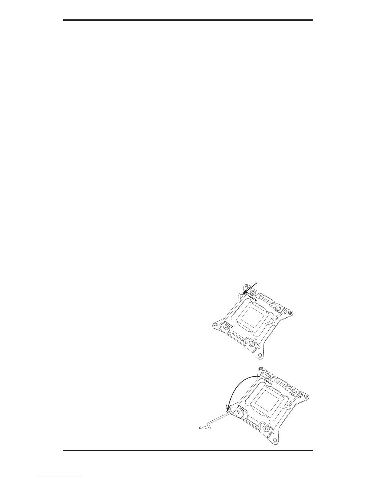
1. There are two levers on the
LGA2011 socket. First press and
release the load lever labeled
'Open 1st'.
2. Press the second load lever
labeled 'Close 1st' to release the
load plate from its locked position.
the lever labeled
'Close 1st'
WARNING!
OPEN 1st
Pull lever away
from the socket
WARNING!
OPEN 1st
3-3
Page 24
SuperWorkstation PIO-737A-i-MA015 User's Manual
WARNING!
OPEN
1st
WARNING!
3. With the lever labeled 'Close 1st'
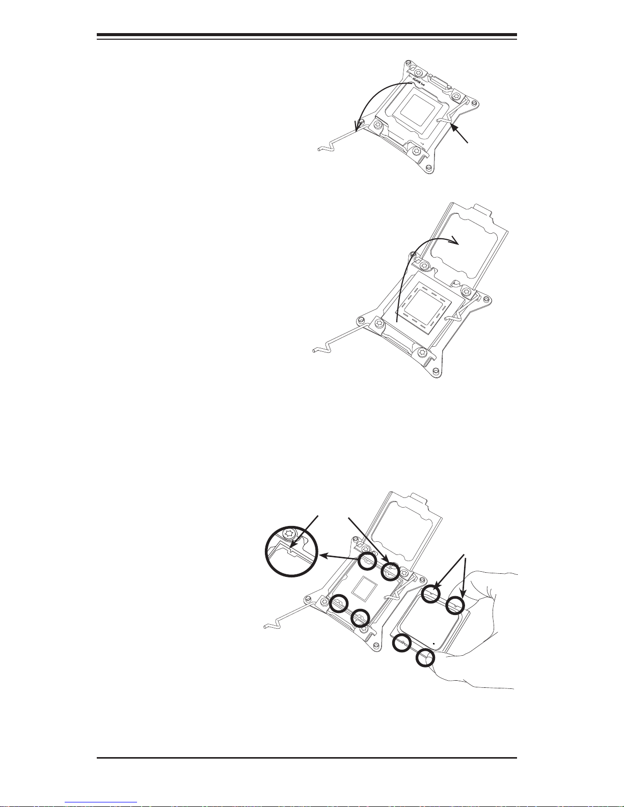
fully retracted, gently push down
on the ' Open 1st ' lever to o pen th e
load plate. Lift the load plate to
open it completely.
4. Using your t humb an d the ind ex
fi nger, remove the ' WAR NIN G'
plastic c ap fr om the so cket.
WARNING!
OPEN 1st
Gently push
down to pop
the load plate
open.
5. Use your thumb and index fi nger
to hold the CPU by its edges. Align
the CPU keys, which are semicircle cutouts, against the socket
keys.
6. Once they are aligned,
carefully lower the CPU
straight down into the
socket. (Do not drop
the CPU on the socket.
Do not move the CPU
horizontally or vertically and do not rub the
CPU against any pins of
the socket, which may
damage the CPU or the
socket.)
WARNING!
Socket Keys
CPU Keys
3-4
Page 25
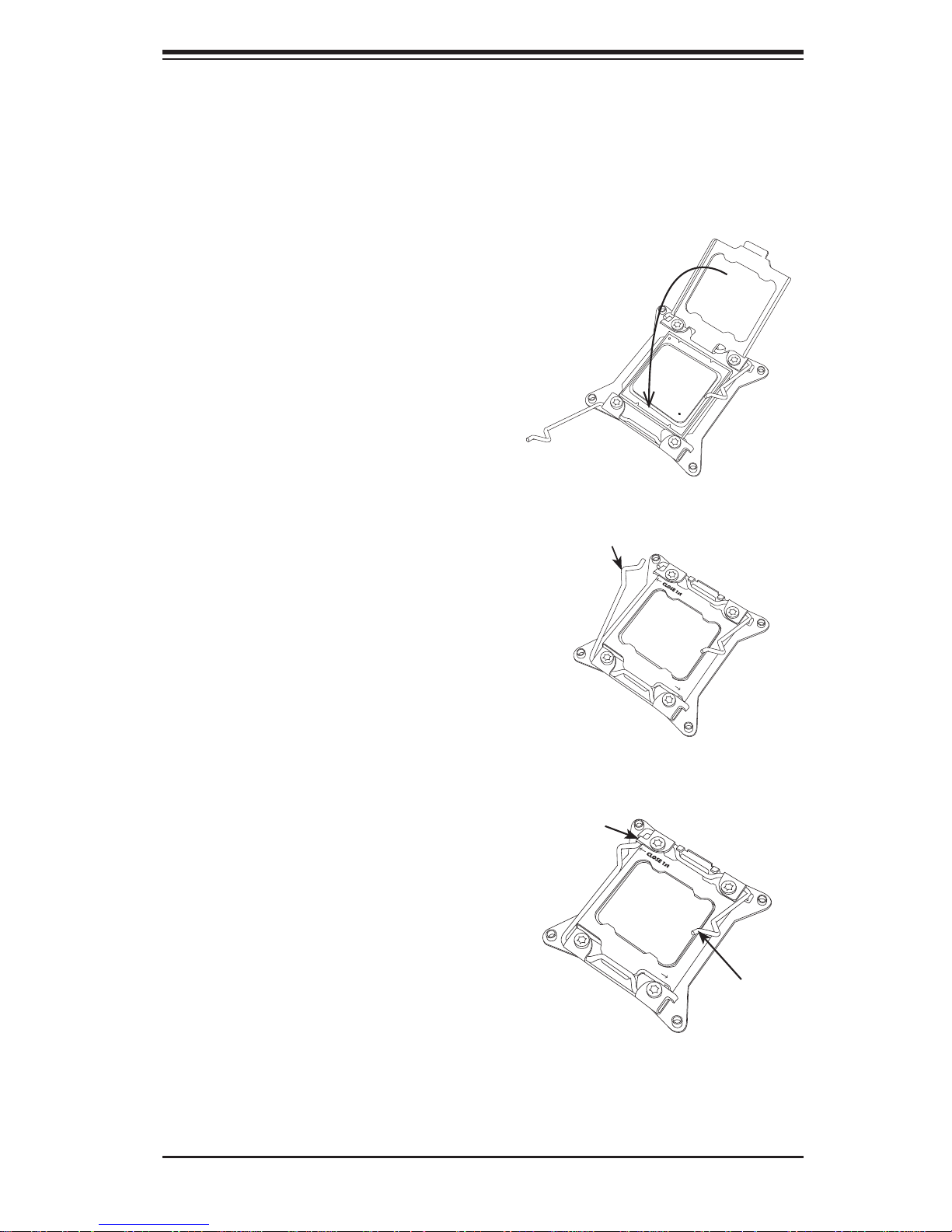
Chapter 3: Component Installation
OPEN 1st
OPEN 1st
Caution: CPUs only install to the socket in one direction. Make sure that the CPU
is properly inserted into the socket before closing the load plate. If it doesn't close
properly, do not force it as it may damage your CPU. Instead, open the load plate
again and double-check that the CPU is aligned properly.
7. With the CPU in the socket, inspect the four corners of the CPU
to make sure that they are fl ush
Gently close
the load plate.
with the socket.
8. Close the load plate. Lock the
lever labeled 'Close 1st', then lock
the lever labeled 'Open 1st'. Use
your thumb to gently push the load
levers down until the lever locks.
Push down and lock the
level labeled 'Close 1st'.
OPEN 1st
Lever Lock
OPEN 1st
Push down
and lock the
lever labeled
'Open 1st'.
3-5
Page 26
SuperWorkstation PIO-737A-i-MA015 User's Manual
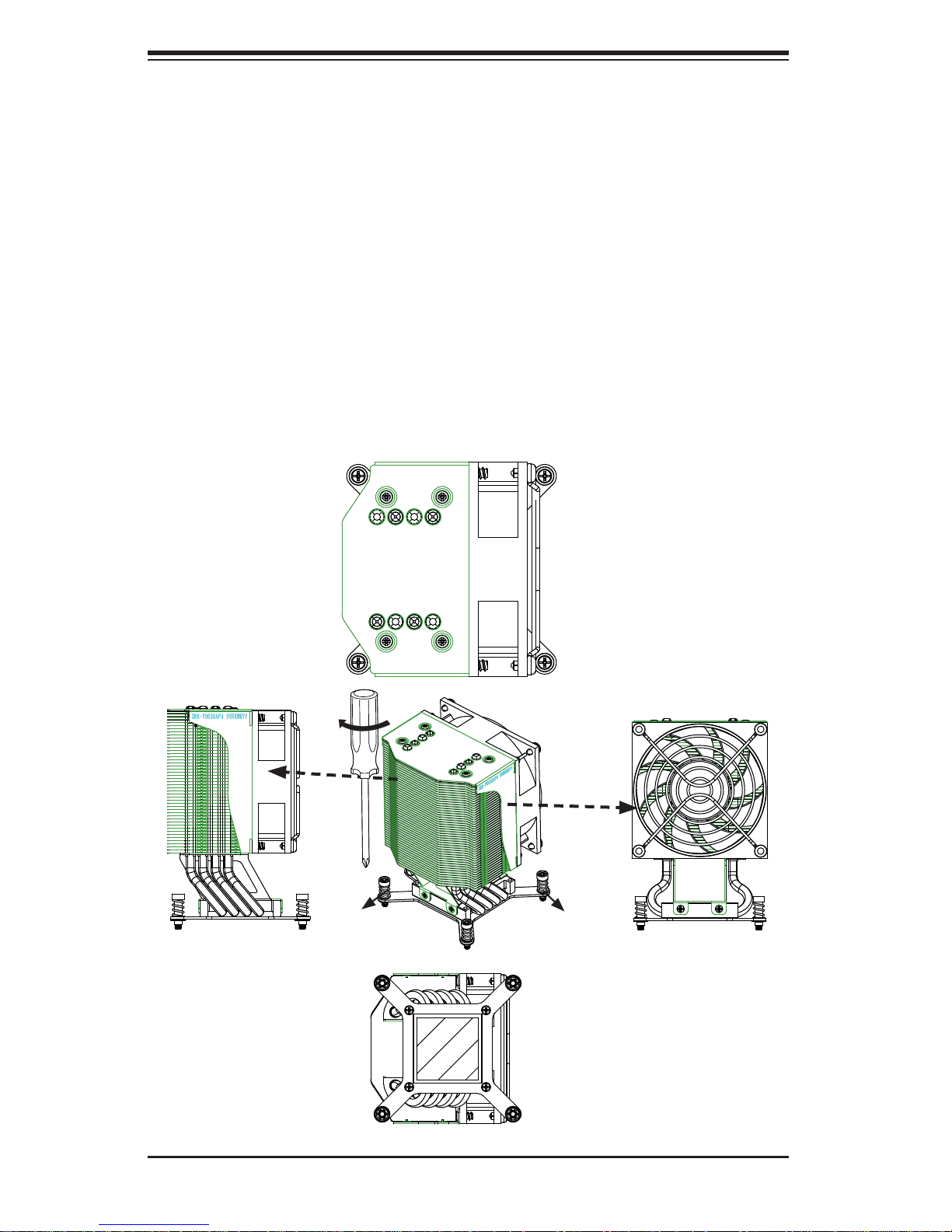
Installing a CPU Heat Sink
1. Do not apply any thermal grease to the heat sink or the CPU die; the required
amount has already been applied.
2. Place the heat sink on top of the CPU so that the four mounting holes are
aligned with those on the motherboard and the heat sink bracket underneath.
3. Screw in two diagonal screws (i.e., the #1 and the #2 screws) until just snug.
(To avoid possible damage to the CPU do not over-tighten the screws.)
4. Finish the installation by fully tightening all four screws.
Figure 3-2. Heat Sink Installation
Side View
Screw#1
Screw#1
Top View
Screw#3
Screw#4
Screw#2Screw#3
Screw#2
Side View
Bottom View
3-6
Page 27
Chapter 3: Component Installation
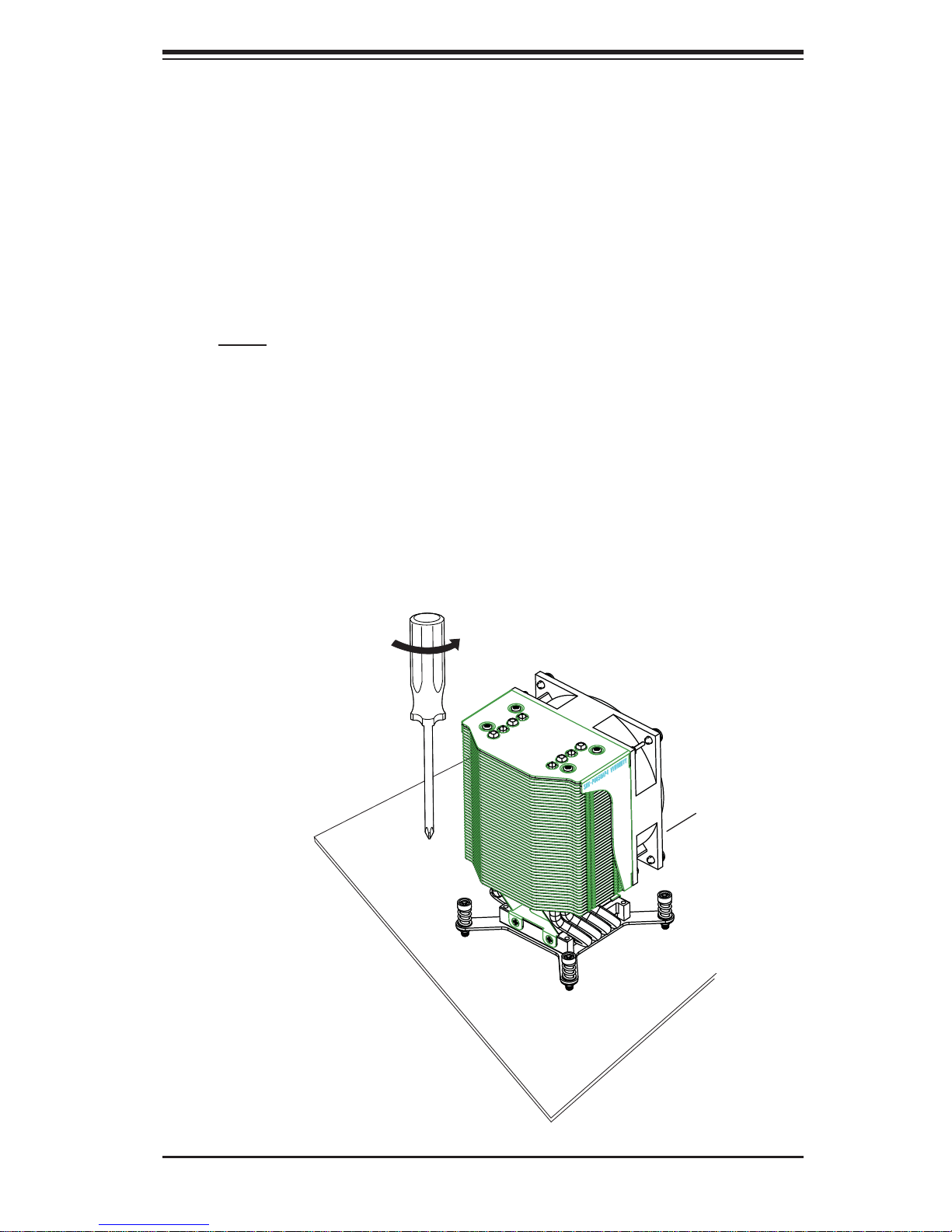
Removing the Heat Sink
Preparation
1. Begin by removing power from the system as described on page 3-1.
2. Remove the power cord from the system before removing the heatsink.
3. Unscrew the heat sink screws from the motherboard in the sequence as
shown in the illustration below.
4. Gently wriggle the heat sink to loosen it from the CPU. (Do not use excessive
force when wriggling the heat sink!)
5. Once the heat sink is loosened, remove it from the CPU socket.
6. Remove the used thermal grease and clean the surface of the CPU and the
heat sink, Reapply the proper amount of thermal grease on the surface before
reinstalling the heat sink.
Figure 3-3. Heat Sink Removal
Loosen screws
in the sequence
shown.
Screw#1
Screw#4
(hidden)
Screw#2
Screw#3
3-7
Page 28
SuperWorkstation PIO-737A-i-MA015 User's Manual
3-5 Installing Memory Modules
Check t he Supe rmic ro Web site fo r rec ommen ded mem or y modul es.
Caution: Exercise extreme care when installing or removing DIMM modules to
prevent any possible damage.
Preparation
1. Begin by removing power from the system as described on page 3-1.
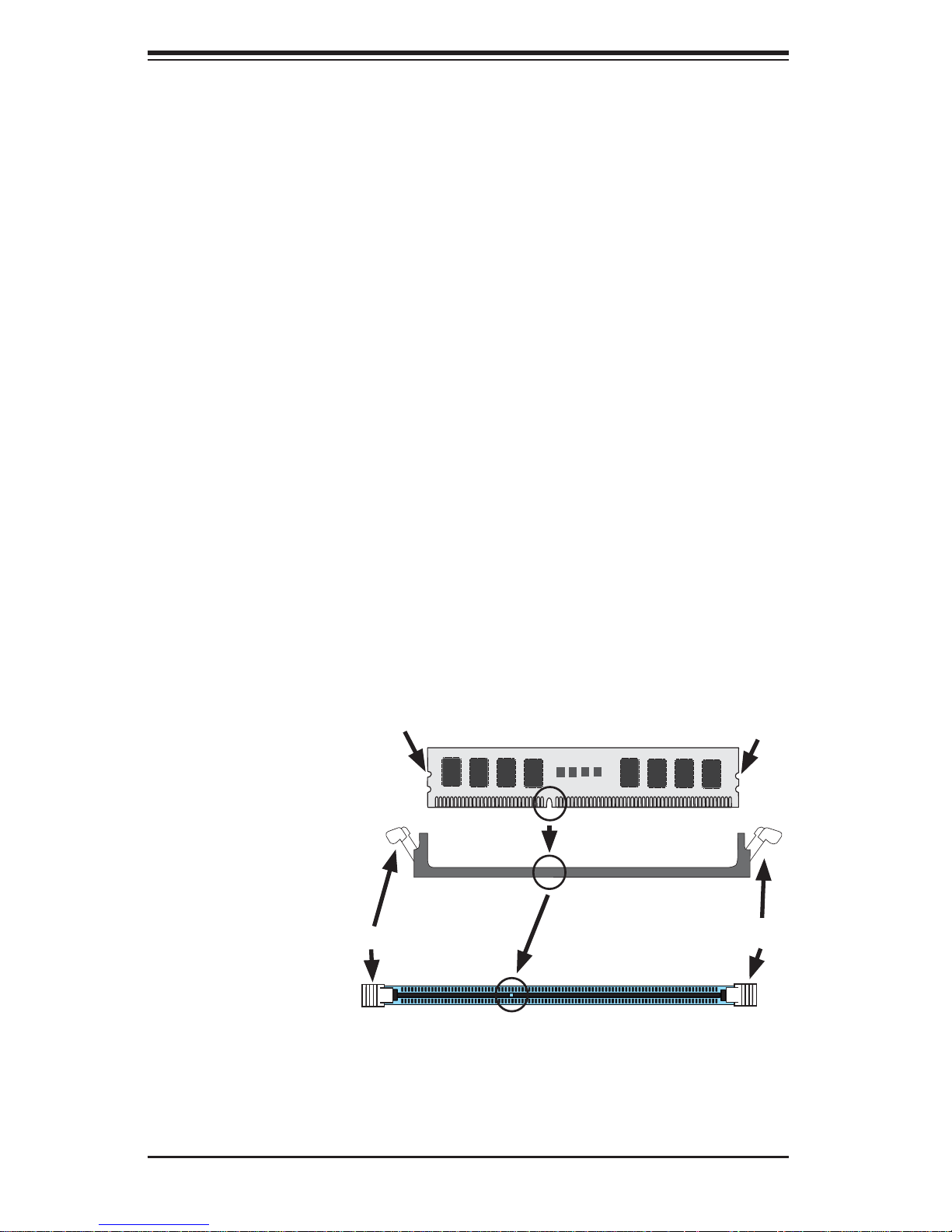
2. Press down the release tabs on the ends of a memory slot. Insert each DIMM
module vertically into its slot. Pay attention to the notch along the bottom of
the module to prevent inserting the DIMM module incorrectly.
3. Using both thumbs, gently press down on the DIMM module until it snaps into
place in the slot. Repeat for all modules.
4. Insert the desired number of DIMMs into the memory slots, starting with P1
DIMM1A. For best performance, please use the memory modules of the same
type and speed in the same bank. See the DIMM Installation Chart on the
following page.
5. Reverse the steps above to remove the DIMMs from the motherboard.
Figure 3-4. DIMM Installation
Notch
To Ins tall : Inser t module
vert ic ally a nd pre ss
down unt il it sn aps in to
place. Pay a tte ntio n to
the ali gnme nt notc h at
the bottom.
To Remove:
Use your thumbs to
gently push the release
tabs near both ends of
the module. This should
release it from the slot.
Release Tab
Note: Notch should align
with the receptive key
point on the slot.
Front View
Notch
Release Tab
Top View of DDR3 Slot
3-8
Page 29
Chapter 3: Component Installation
Memory Support
The Super Workstation supports up to 512 GB of registered/unbuffered load reducing ECC DDR3 1333/1066/833 memory in 16 DIMM slots. For the latest memory
updates, please refer to the product page on the Supermicro website.
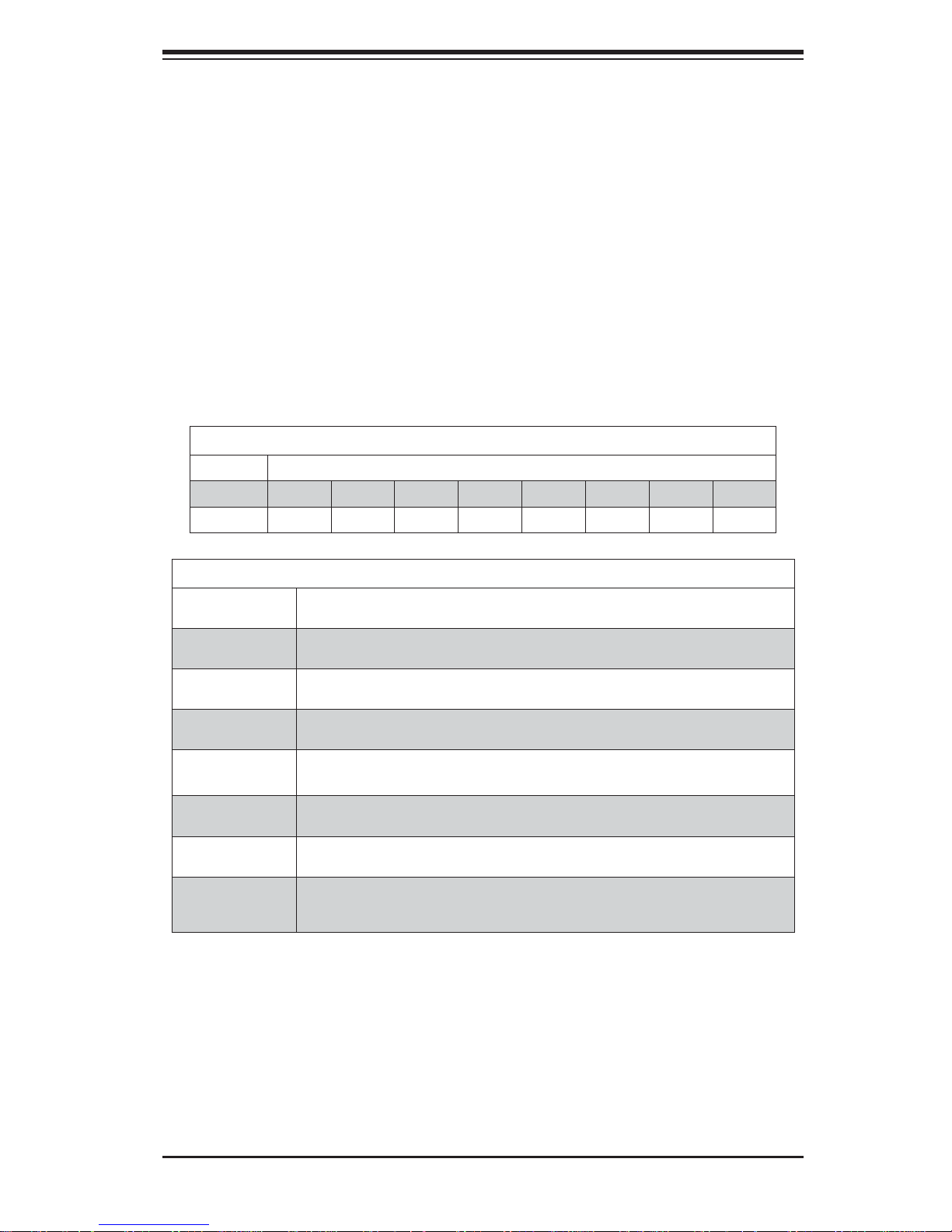
Order of Populating DIMM Slots
For memory to work properly , follow the table below for the correct order of populating the DIMM slots. See the serverboad layout page for slot numbering.
Notes: an "X" indicates a slot populated with a memory module.
Populate the "A" DIMM slots fi rst. Any of the slots may be used. Populate the "B"
slots only after all "A" slots have been fi lled.
Processors and their Corresponding DIMM Slots
CPU# Corresponding DIMM Modules
CPU 1 P1-A1 P1-B1 P1-C1 P1-D1 P1-A2 P1-B2 P1-C2 P1-D2
CPU 2 P2-E1 P2-F1 P2-G1 P4-H1 P2-E2 P2-F2 P2-G2 P2-H2
Number of
CPUs+DIMMs
1 CPU &
2 DIMMs
1 CPU &
4 DIMMs
1 CPU &
5~8 DIMMs
2 CPUs &
4 DIMMs
2 CPUs &
6 DIMMs
2 CPUs &
8 DIMMs
2 CPUs &
10~16 DIMMs
Processor and Memory Module Population
CPU and Memory Population Confi guration Table
(For memory to work proper, please install DIMMs in pairs.)
CPU1
P1-A1/P1-B1
CPU1
P1-A1/P1-B1, P1-C1/P1-D1
CPU1
P1-A1/P1-B1, P1-C1/P1-D1 + Any memory pairs in P1-A2/-B2/-C2/-D2 DIMM slots
CPU1 + CPU2
P1-A1/P1-B1, P2-E1/P2-F1
CPU1 + CPU2
P1-A1/P1-B1/ P1-C1, P2-E1/P2-F1/P2-G1
CPU1 + CPU2
P1-A1/P1-B1/ P1-C1/P1-D1, P2-E1/P2-F1/P2-G1/P2-H1
CPU1/CPU2
P1-A1/P1-B1/ P1-C1/P1-D1/P1-A2, P2-E1/P2-F1/P2-G1/P2-H1+/P2-E2, Any memory
pairs in P1, P2 DIMM slots
3-9
Page 30
SuperWorkstation PIO-737A-i-MA015 User's Manual
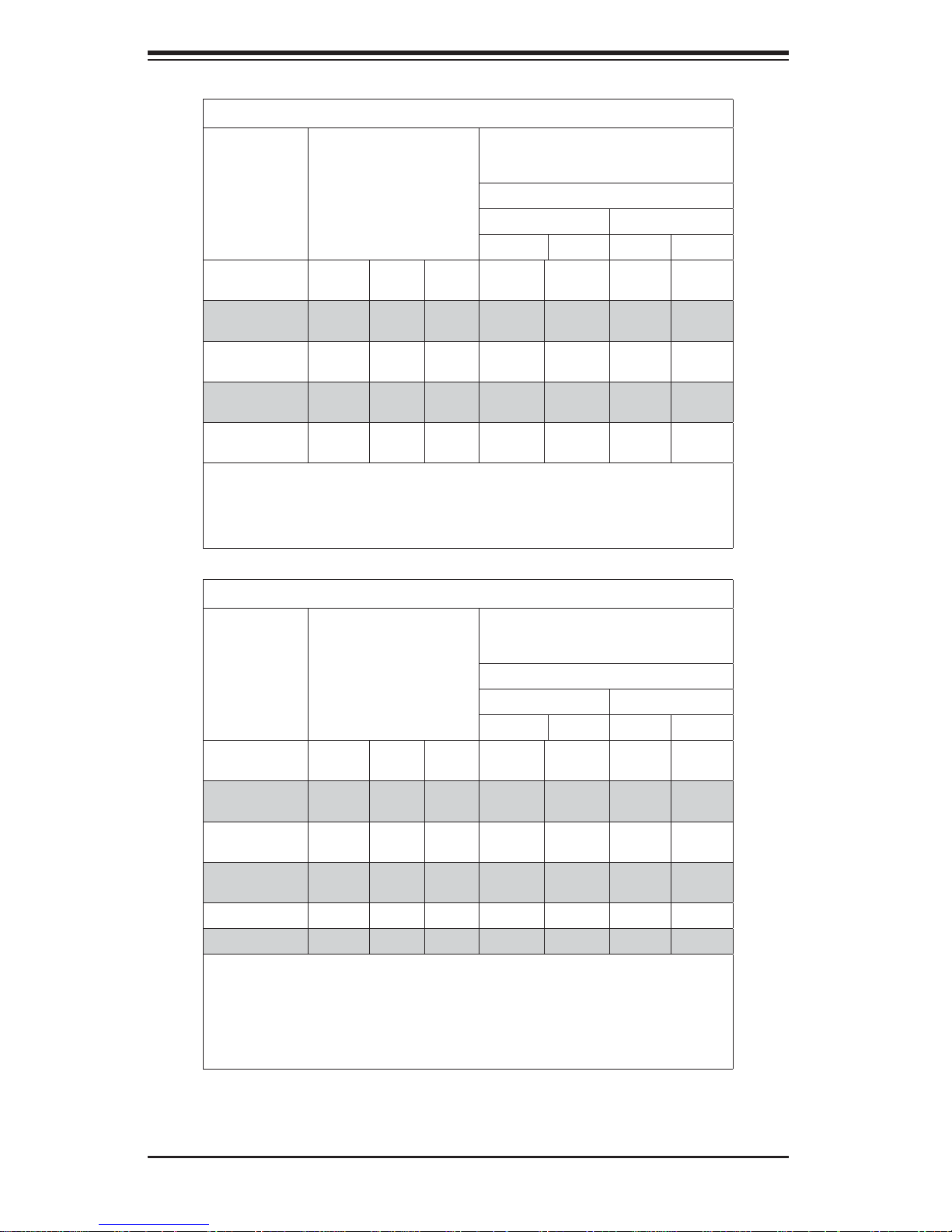
UDIMM Memory Support
Ranks Per
DIMM & Data
Width
SRx8
Non-ECC
DRx8
Non-ECC
SRx16
Non-ECC
SRx8 ECC 1GB 2GB 4GB 1066,
DRx8 ECC 2GB 4GB 8GB 1066,
Notes:
1. 1Gb/2Gb/4Gb DRAMs are supported; however, only 2Gb and 4Gb DRAMs are validated.
2. Command Address Timing is 1N for 1DPC and 2N for 2DPC.
3. ES-4600 4S platforms do not support 3DPC UDIMMs.
4. Please refer to the ES-4600 Platform Design Guide for memory population rules.
Memory Capacity
Per DIMM (Note 1)
1GB 2GB 4GB n/a 1066,
2GB 4GB 8GB n/a 1066,
512MB 1GB 2GB n/a 1066,
Speed (MT/s) and Voltage Validated by
Slot Per Channel (SPC) and DIMM Per
Channel (DPC) (Notes 2, 3, 4)
1DPC 2DPC
1.35V 1.5V 1.35V 1.5V
1333
1333
2 Slots Per Channel
1333
1333
1333
1066,
1333
1066,
1333
n/a 1066,
n/a 1066,
n/a 1066,
1066 1066,
1066 1066,
1333
1333
1333
1333
1333
RDIMM Memory Support
Ranks Per
DIMM & Data
Width
SRx8 1GB 2GB 4GB 1066,
DRx8 2GB 4GB 8GB 1066,
SRx4 2GB 4GB 8GB 1066,
DRx4 4GB 8GB 16GB 1066,
QRx4 8GB 16GB 32GB 800 1066 800 800
QRx8 4GB 8GB 16GB 800 1066 800 800
Notes:
1. 1Gb/2Gb/4Gb DRAMs are supported; however, only 2Gb and 4Gb DRAMs are validated.
2. Command Address Timing is 1N.
3. Please refer to the ES-4600 Platform Design Guide for memory population rules.
4. QR RDIMMs are supported but not validated. Memory testing are limited to system level
testing. Signal integrity testing in interoperability testing are not performed. The passing QR
RDIMMs will be posted on the website.
Memory Capacity
Per DIMM (Note 1)
Speed (MT/s) and Voltage Validated by
Slot Per Channel (SPC) and DIMM Per
Channel (DPC) (Notes 2, 3, 4)
2 Slots Per Channel
1DPC 2DPC
1.35V 1.5V 1.35V 1.5V
1333
1333
1333
1333
1066,
1333
1066,
1333
1066,
1333
1066,
1333
1066 1066,
1333
1066 1066,
1333
1066 1066,
1333
1066 1066,
1333
3-10
Page 31
Chapter 3: Component Installation
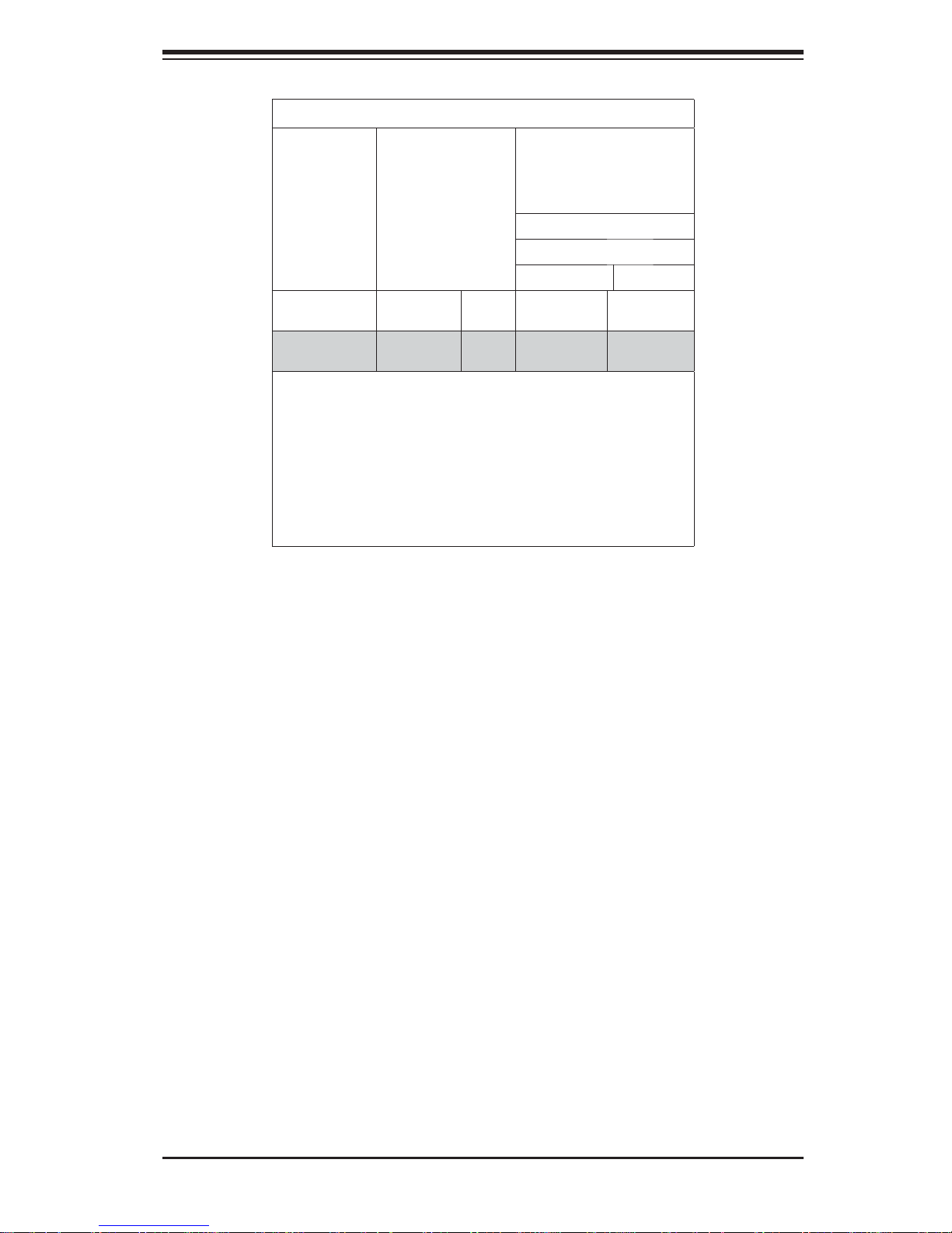
LRDIMM Memory Support
Ranks Per
DIMM & Data
Width (Note 1)
QRx4 (DDP)
(Note 7)
QRx8 (P)
(Note 8)
Notes:
1. Physical Rank is used to calculate DIMM capacity.
2. Command Address Timing is 1N.
3. Only 2Gb/4Gb DRAMs are supported and validated.
4. The speeds listed are estimated only and will be verifi ed through
simulation.
5. Please refer to the ES-4600 Platform Design Guide for memory
population rules.
6. For 3SPC/3DPC-Rank Multiplication (RM) is >=2.
7. DDP is for Dual Die Package DRAM stacking.
8. "P" Means "Planer Monolithic DRAM Die."
Memory Capacity
Per DIMM (Note 2)
16GB 32GB 1066 1066, 1333
8GB 16GB 1066 1066, 1333
Speed (MT/s) and Voltage
Validated by Slot Per
Channel (SPC) and DIMM
Per Channel (DPC) (Notes
3, 4, 5, 6)
2 Slots Per Channel
1DPC/2DPC
1.35V 1.5V
Notes and Restrictions
• For the memory modules to work properly, please install DIMM modules in pairs
(with an even number of DIMMs installed).
• All channels in a system will run at the fastest common frequency.
3-11
Page 32
SuperWorkstation PIO-737A-i-MA015 User's Manual
3-6 System Fan
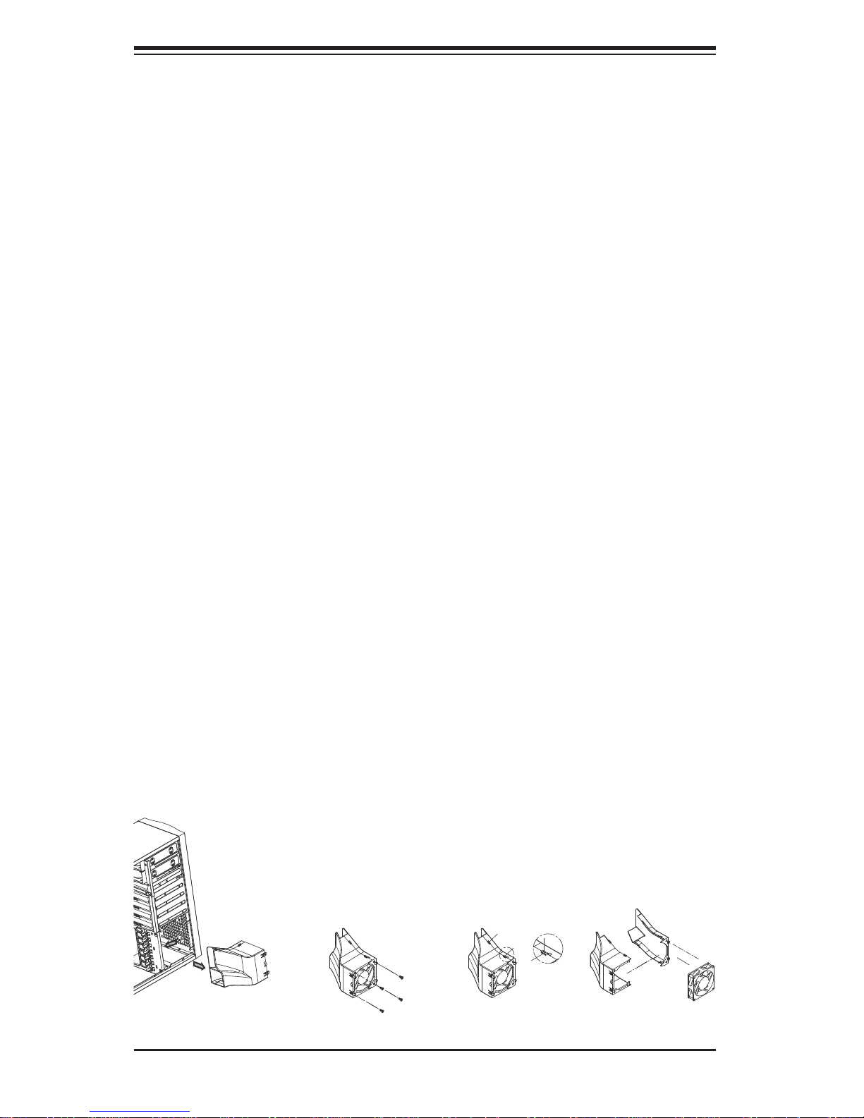
A 12-cm chassis cooling fan housed in a fan duct is located just below the peripheral
drive bays to provide cool air intake for the system.
Preparation
Under normal operation, the chassis fan and the exhaust fan run continuously. The
chassis fan is hot-pluggable and can be replaced without powering down the system.
Removing a Fan
1. Release the clips that secure the fan duct to the chassis. You can then pull
the fan duct out from its location in the chassis.
2. Remove the four screws at the front of the fan duct that hold the fan in place.
Then release the two fasteners along the side of the fan duct.
3. You can now separate it into two pieces and easily remove the fan. Add a
new fan of the same type.
Installing a New Fan
1. Replace the failed fan with an identical one (available from Supermicro)
2. Install it in the same position and orientation as the one you removed.
3. Check that the fan is working, then replace the chassis cover.
Figure 3-5. Removing the Fan Duct Assembly
3-12
Page 33

Chapter 3: Component Installation
3-7 Hard Drive Installation
A total of four SATA drives may be housed in the PIO-737A-i-MA015. The drive
IDs are preconfi gured as 0 through 3 in order from bottom to top. Remove the side
panel of the chassis to access these drives as described previously in this chapter.
Caution: Regardless of how many SATA drives are installed, all drive carriers must
remain in the drive bays to promote proper airfl ow.
Preparation
The SATA drives are hot-pluggable, meaning they can be removed and installed
without powering down the system.
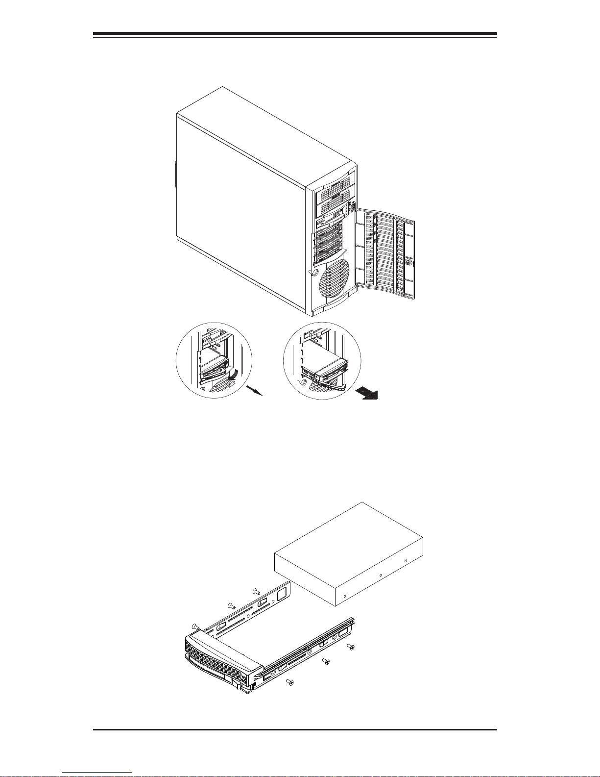
Removing SATA Drives
1. To remove a carrier, fi rst open the front bezel then push the release button
located beside the drive LEDs.
2. Swing the colored handle fully out and use it to pull the unit straight out.
Mounting a SATA Drive in a Drive Carrier
1. Insert the drive into the carrier with the printed circuit board side facing down
so that the mounting holes align with those in the carrier.
2. Secure the drive to the carrier with four screws.
3. Insert the carrier back into the empty bay.
4. When fully in, close the handle to seat the carrier into the back plane.
3-13
Page 34
SuperWorkstation PIO-737A-i-MA015 User's Manual
Figure 3-6. Removing the Drive Carrier
Figure 3-7. Removing a Hard Drive from the Drive Carrier
3-14
Page 35

Chapter 3: Component Installation
Installing Components in the 5.25" Drive Bays
The PIO-737A-i-MA015 has two 5.25" drive bays above the SATA drive bays.
Components such as a hard drives or CD-ROM drives can be installed in these
5.25" drive bays.
Preparation
Begin by removing power from the system as described on page 3-1.
Accessing the Drive Bays
1. Remove the top/left chassis cover to access the interior of the system.
2. With the cover off, remove the two or four screws that secure the drive bay to
the chassis (one side only) then push the entire empty drive carrier out from
the back.
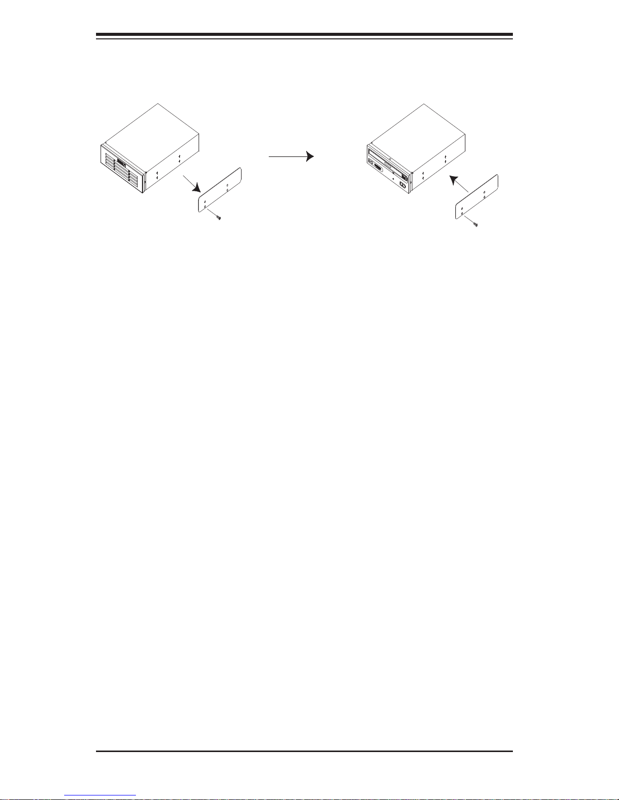
Adding a CD-ROM Drive
1. Remove the guide plate from right side of the empty drive carrier and screw it
into the right side of the CD-ROM drive using the holes provided.
2. Slide the CD-ROM into the bay and secure it to the chassis with the drive
carrier screws you fi rst removed.
3. Attach the power and data cables to the drive.
4. Replace the top/left chassis cover before restoring power to the system.
Adding a Hard Drive
1. Install a hard drive into one of the removed empty drive carriers with the
printed circuit board side toward the carrier so that the drive's mounting holes
align with those in the carrier.
2. Secure the drive to the carrier with four screws then slide the assembly into
the bay and secure it to the chassis with the drive carrier screws you fi rst
removed.
3. Attach the power and data cables to the drive.
4. Replace the top/left chassis cover before restoring power to the system.
3-15
Page 36
SuperWorkstation PIO-737A-i-MA015 User's Manual
Figure 3-8. Adding a Component Without a Drive Carrier
3-8 Power Supply
The PIO-737A-i-MA015 includes a single 665 Watt power supply. In the unlikely
event that it becomes necessary to replace the power supply, follow the instructions below..
Preparation
Begin by removing power from the system as described on page 3-1.
Changing the Power Supply
1. Remove the power supply connectors going to the motherboard and the SATA
backplane.
2. Remove the screws that secure the unit to the mounting brackets in the chassis and then pull the unit completely out.
3. Replace the failed power supply with another having the exact same part
number (PWS-665-PQ). Gently but fi rmly push the new unit all the way into
the open bay.
4. Secure it to the mounting brackets in the chassis with the screws provided.
5. Connect two power cables to the SATA backplane and two to the motherboard power connectors.
6. Finish by replacing the chassis left cover and then restoring power to the
system.
3-16
Page 37
Chapter 3: Component Installation
3-9 Motherboard Battery
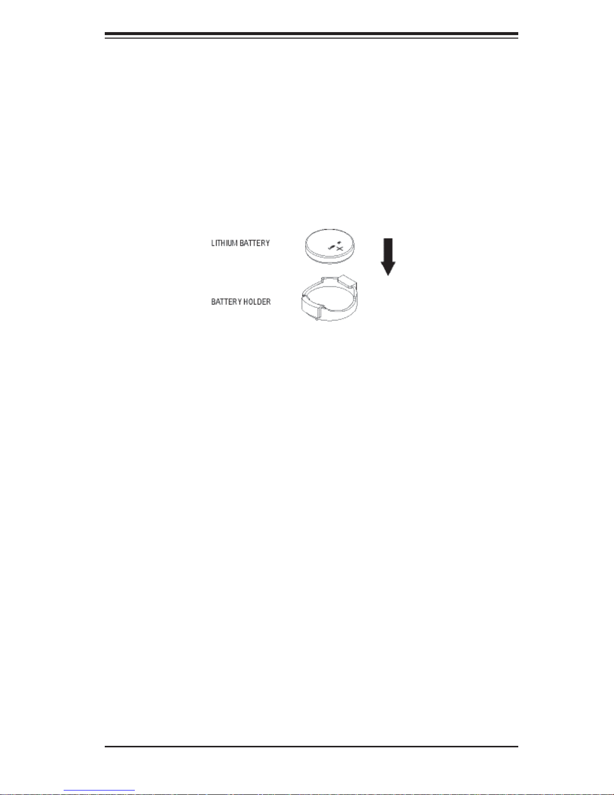
CAUTION: There is a danger of explosion if the onboard battery is installed upside
down, which will reverse its polarities (see Figure 3-12). This battery must be replaced only with the same or an equivalent type recommended by the manufacturer
(CR2032). Dispose of used batteries according to the manufacturer's instructions.
Figure 3-9. Installing the Onboard Battery
Please handle used batteries carefully. Do not damage the battery in any way; a
damaged battery may release hazardous materials into the environment. Do not
discard a used battery in the garbage or a public landfi ll. Please comply with the
regulations set up by your local hazardous waste management agency to dispose
of your used battery properly.
3-17
Page 38

SuperWorkstation PIO-737A-i-MA015 User's Manual
Notes
3-18
Page 39

Appendix A: Software
Appendix A
Software
A-1 Operating System
The PIO-537A-i-MA015 supports the Windows 7 Professional 64-bit Operating
System. This OS has been pre-installed to the system.
System Recovery Instructions
This computer includes a hidden partition which contains a backup of your factory
Windows installation. In case of a system failure, you can use this backup to restore
your computer to a working state in just a few minutes.
Since this backup resides on the same physical hard-disk as your current Windows
installation, a hardware failure of the hard-disk will prevent you from reinstalling
Windows. There are two different ways to initiate a system recovery of your system:
• Trigger recovery from OS level (run FullRestore.exe)
• Trigger recovery during system boot up (press F10 key).
Warning: System Recovery will wipe all of your personal data and restore the system
to OOBE. You must have your CD-KEY from COA label ready before performing this
action. System Recovery is an automated, one-step process. Do not initiate a system
recovery unless you are prepared for a complete re-installation back to the factory
default installation.
Support
If you require technical help for any Operating System problems, please contact your
3rd party software vendor or Technical Support at Supermicro. Contact information is
provided in Chapter 1.
A-1
Page 40

SuperWorkstation PIO-537A-i-MA015 User's Manual
A-2 Installing Drivers
With the hardware and operating system installed, you may need to install the
drivers if not done already.
The drivers are available online at http://www.supermicro.com/support/resources/
Obtaining Drivers
1. Go to the Advanced Search area and select the Category (motherboards),
Product Type and Model (motherboard model) from the drop-down menus.
2. Click Submit Request.
3. The following page will display a Drivers and Utilities section. Use the dropdown menus to select the OS and device type.
4. Click Submit to get the correct driver for your system.
A-2
Page 41
Appendix A: Software
A-3 SuperDoctor III
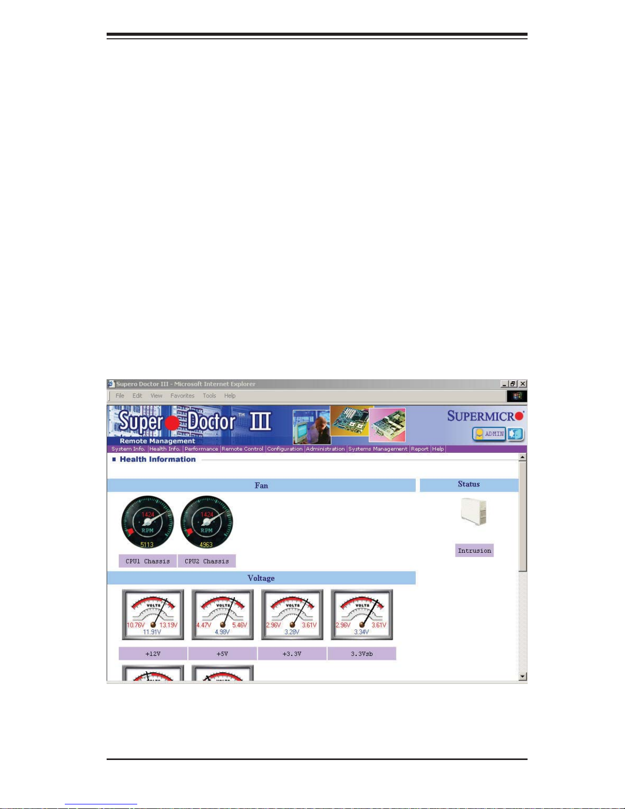
The SuperDoctor® III program is a Web based management tool that supports
remote management capability. It includes Remote and Local Management tools.
The local management is called SD III Client. The SuperDoctor III program included
on the CD-ROM that came with your motherboard allows you to monitor the environment and operations of your system. SuperDoctor III displays crucial system
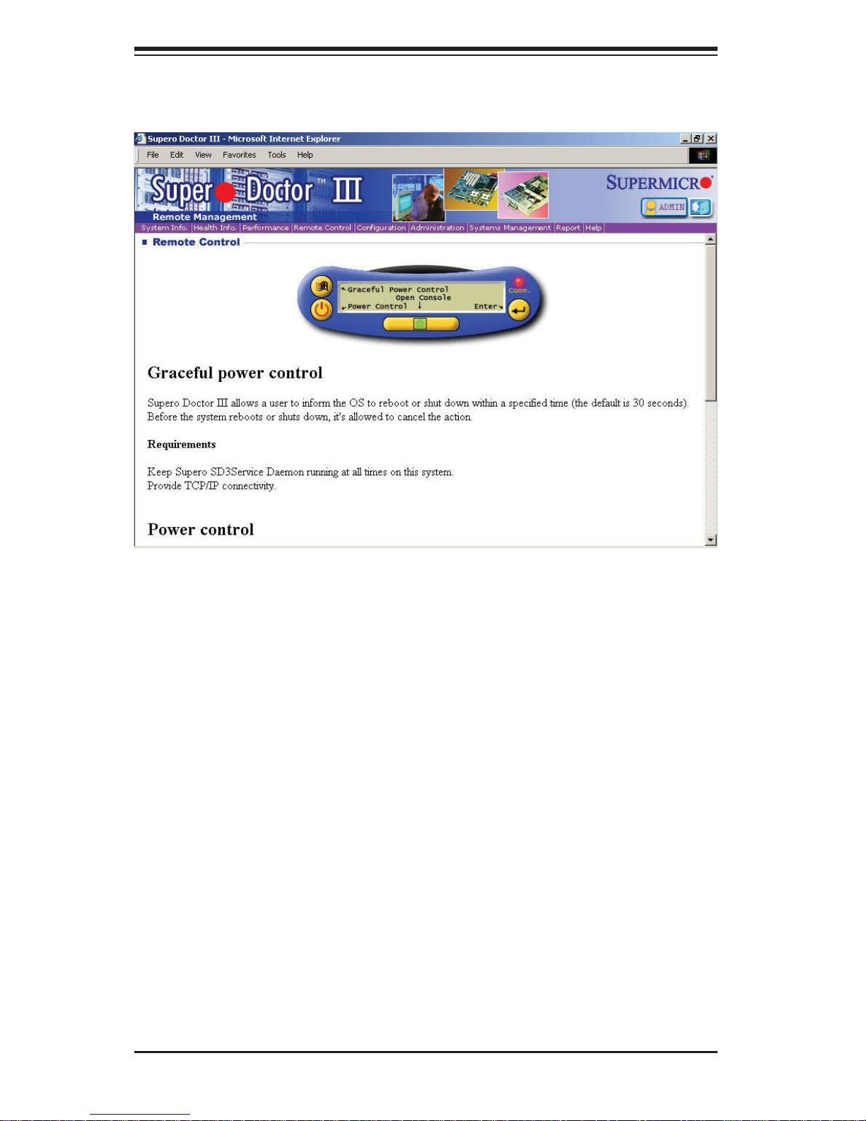
information such as CPU temperature, system voltages and fan status. See the
Figure below for a display of the SuperDoctor III interface.
Note: The default User Name and Password for SuperDoctor III is ADMIN / ADMIN.
Note: When SuperDoctor is fi rst installed, it adopts the temperature threshold set-
tings that have been set in BIOS. Any subsequent changes to these thresholds
must be made within SuperDoctor, as the SuperDoctor settings override the BIOS
settings. To set the BIOS temperature threshold settings again, you would fi rst need
to uninstall SuperDoctor.
Supero Doctor III Interface Display Screen (Health Information)
A-3
Page 42
SuperWorkstation PIO-537A-i-MA015 User's Manual
Supero Doctor III Interface Display Screen (Remote Control)
Note: The SuperDoctor III program and User's Manual can be downloaded from the
Supermicro Web site at http://www.supermicro.com/products/accessories/software/
SuperDoctorIII.cfm.
For Linux, we recommend using SuperDoctor II.
A-4 BIOS
The AMI ROM BIOS is stored in a Flash EEPROM and can be easily updated. This
chapter describes the basic navigation of the AMI BIOS Setup Utility setup screens.
Note: For instructions on BIOS recovery , please refer to the instruction guide posted
at http://www.supermicro.com/support/manuals/.
Starting BIOS Setup Utility
To enter the AMI BIOS Setup Utility screens, press the <Delete> key while the
system is booting up.
Note: In most cases, the <Delete> key is used to invoke the AMI BIOS setup screen.
There are a few cases when other keys are used, such as <F1>, <F2>, etc.
The Main BIOS setup menu screen has two main frames. The left frame displays
all the options. Grayed-out options cannot be confi gured. Options in blue can be
A-4
Page 43

Appendix A: Software
confi gured by the user. The right frame displays the key legend. Above the key
legend is an area reserved for a description of the highlighted option. When an
option is selected in the left frame, it is highlighted in white. Often a text message
will accompany it. (The AMI BIOS has default text messages built in. Supermicro
retains the option to include, omit, or change any of these text messages.)
The AMI BIOS Setup Utility uses a key-based navigation system called "hot keys".
Most of the AMI BIOS setup utility "hot keys" can be used at any time during the
setup navigation process. These keys include <F1>, <F10>, <Enter>, <ESC>, arrow keys, etc.
How To Change the Confi guration Data
The confi guration data that determines the system parameters may be changed by
entering the AMI BIOS Setup utility. This Setup utility can be accessed by pressing
<Del> at the appropriate time during system boot.
How to Start the Setup Utility
Normally, the only visible Power-On Self-Test (POST) routine is the memory test.
As the memory is being tested, press the <Delete> key to enter the main menu of
the AMI BIOS Setup Utility. From the main menu, you can access the other setup
screens. An AMI BIOS identifi cation string is displayed at the left bottom corner of
the screen, below the copyright message.
Important: Do not upgrade the BIOS unless your system has a BIOS-related issue.
Flashing the wrong BIOS can cause irreparable damage to the system. In no event
shall Supermicro be liable for direct, indirect, special, incidental, or consequential
damages arising from a BIOS update. If you have to update the BIOS, do not shut
down or reset the system while the BIOS is updating. This is to avoid possible
boot failure.
A-5
Page 44

SuperWorkstation PIO-537A-i-MA015 User's Manual
Notes
A-6
Page 45
Appendix B: BIOS Beep Codes
Appendix B
BIOS Beep Codes
During the POST (Power-On Self-Test) routines, which are performed each time
the system is powered on, errors may occur.
Non-fatal errors are those which, in most cases, allow the system to continue
with bootup. The error messages normally appear on the screen.
Fatal errors will not allow the system to continue to bootup. If a fatal error occurs, you should consult with your system manufacturer for possible repairs.
These errors are usually communicated through a series of audible beeps. The
numbers on the list correspond to the number of beeps for the corresponding
error.
BIOS Beep Codes
Beep Code/LED Message Description
1 beep Refresh Circuits have been reset.
(Ready to power up)
5 short beeps + 1 long
beep
5 beeps Display memory
1 beep per device Refresh 1 beep for each USB device
OH LED On System OH System Overheat
Memory error No memory detected in the
system
Video adapter missing or with
read/write error
faulty memory
B-1
Page 46

SuperWorkstation PIO-737A-i-MA015 User's Manual
Notes
B-2
Page 47

Appendix C: System Specifi cations
Appendix C
System Specifi cations
Processors
Two Intel E5-2600 processors in LGA 2011 sockets
Note: Please refer to our web site for a complete listing of supported processors.
Chipset
Intel C600
BIOS
8 Mb AMI S PI Flash EEPROM
Memory Capacity
Sixteen DIMM sockets supporting up to 512 GB of registered/unbuffered ECC
DDR3-1333/1066/800 LRDIMMs
Note: See the memory section for details.
SATA Controller
Intel on- ch ip cont roller f or six-p or t SATA 3. 0/2.0 (R A ID suppo rte d)
Drive Bays
Eight hot- swap dr ive bays to hou se eight S AS or six S ATA dr ives
Perip hera l Dri ve Bays
Two 5.25 " drive bays
Expansion Slots
Supports the use of six standard size PCI add-on cards: three PCI-E 3.0 x16, two
PCI-E 3.0 x8 and one PCI-E 3.0 x4 slots.
Motherboard
X9DAi (Extended ATX form factor)
Dimensions: 12" x 13" (305 x 330 mm)
C-1
Page 48

SuperWorkstation PIO-737A-i-MA015 User's Manual
Chassis
SC733TQ-665B (Mid-tower)
Dimensions: (WxHxD) 7 x 16.8 x 20.9 in. (178 x 427 x 531 mm)
Weight
Gross (Bare Bone): 43 lbs. (19.5 kg.)
System Cooling
One 12-cm chassis fan
System Input Requirements
AC Input Voltage: 100-240 VAC
Rated Input Current: 10A (100V) to 5A (240V)
Rated Input Frequency: 50/60 Hz
Power Supply
Rated Output Power: 665W (Part# PWS-665-PQ)
Rated Output Voltages: +3.3V (24A), +5V (30A), +12V (54A), -12V (0.5A), +5Vsb
(6A)
Operating Environment
Operating Temperature: 10º to 35º C (50º to 95º F)
Non-Operating Temperature: -40º to 70º C (-40º to 158º F)
Operating Relative Humidity: 8% to 90% (non-condensing)
Non-Operating Relative Humidity: 5 to 95% (non-condensing)
Regulatory Compliance
Electromagnetic Emissions: FCC Class B, EN 55022 Class B, EN 61000-3-2/-33, CISPR 22 Class B
Electromagnetic Immunity: EN 55024/CISPR 24, (EN 61000-4-2, EN 61000-4-3,
EN 61000-4-4, EN 61000-4-5, EN 61000-4-6, EN 61000-4-8, EN 61000-4-11)
Safety: CSA/EN/IEC/UL 60950-1 Compliant, UL or CSA Listed (USA and
Canada), CE Marking (Europe)
California Best Management Practices Regulations for Perchlorate Materials:
This Perchlorate warning applies only to products containing CR (Manganese
Dioxide) Lithium coin cells. “Perchlorate Material-special handling may apply. See
www.dtsc.ca.gov/hazardouswaste/perchlorate”
C-2
Page 49

Notes
Appendix C: System Specifi cations
C-3
Page 50

SuperWorkstation PIO-737A-i-MA015 User's Manual
The products sold by Supermicro are not intended for and will not be used in life support systems,
medical equipment, nuclear facilities or systems, aircraft, aircraft devices, aircraft/emergency communication devices or other critical systems whose failure to perform be reasonably expected to
result in signifi cant injury or loss of life or catastrophic property damage. Accordingly, Supermicro dis-
claims any and all liability, and should buyer use or sell such products for use in such ultra-hazardous
applications, it does so entirely at its own risk. Furthermore, buyer agrees to fully indemnify, defend
and hold Supermicro harmless for and against any and all claims, demands, actions, litigation, and
proceedings of any kind arising out of or related to such ultra-hazardous use or sale.
(continued from front)
C-4
 Loading...