

Supero SuperWorkstation 5037A-i2-MA015, SuperWorkstation PIO-537A-i-MA015 User Manual
SUPER
SuperWorkstation
5037A-i2-MA015
®
USER’S MANUAL
1.0

The information in this User’s Manual has been carefully reviewed and is believed to be accurate.
The vendor assumes no responsibility for any inaccuracies that may be contained in this document,
makes no commitment to update or to keep current the information in this manual, or to notify any
person or organization of the updates. Please Note: For the most up-to-date version of this
manual, please see our web site at www.supermicro.com.
Super Micro Computer, Inc. ("Supermicro") reserves the right to make changes to the product
described in this manual at any time and without notice. This product, including software and documentation, is the property of Supermicro and/or its licensors, and is supplied only under a license.
Any use or reproduction of this product is not allowed, except as expressly permitted by the terms
of said license.
IN NO EVENT WILL SUPERMICRO BE LIABLE FOR DIRECT, INDIRECT, SPECIAL, INCIDENTAL,
SPECULATIVE OR CONSEQUENTIAL DAMAGES ARISING FROM THE USE OR INABILITY TO
USE THIS PRODUCT OR DOCUMENTATION, EVEN IF ADVISED OF THE POSSIBILITY OF
SUCH DAMAGES. IN PARTICULAR, SUPERMICRO SHALL NOT HAVE LIABILITY FOR ANY
HARDWARE, SOFTW ARE, OR DA TA STORED OR USED WITH THE PRODUCT, INCLUDING THE
COSTS OF REPAIRING, REPLACING, INTEGRATING, INSTALLING OR RECOVERING SUCH
HARDWARE, SOFTWARE, OR DATA.
Any disputes arising between manufacturer and customer shall be governed by the laws of Santa
Clara County in the State of California, USA. The State of California, County of Santa Clara shall
be the exclusive venue for the resolution of any such disputes. Super Micro's total liability for all
claims will not exceed the price paid for the hardware product.
FCC Statement: This equipment has been tested and found to comply with the limits for a class B
digital device, pursuant to Part 15 of the FCC Rules. These limits are designed to provide reasonable
protection against harmful interference in a residential installation. This equipment generates, uses,
and can radiate radio frequency energy and, if not installed and used in accordance with the instructions, may cause harmful interference to radio communications. However, there is no guarantee that
interference will not occur in a particular installation. If this equipment does cause harmful interference to radio or television reception, which can be determined by turning the equipment off and on,
the user is encouraged to try to correct the interference by one or more of the following measures:
• Reorient or relocate the receiving antenna.
• Increase the separation between the equipment and receiver.
• Connect the equipment to an outlet on a circuit different from that to which the receiver
is connected.
• Consult the authorized dealer or an experienced radio/TV technician for help.
California Best Management Practices Regulations for Perchlorate Materials: This Perchlorate warning applies only to products containing CR (Manganese Dioxide) Lithium coin cells. “Perchlorate
Material-special handling may apply. See www.dtsc.ca.gov/hazardouswaste/perchlorate”
WARNING: Handling of lead solder materials used in this
product may expose you to lead, a chemical known to the
State of California to cause birth defects and other reproductive harm.
Manual Revision 1.0
Release Date: October 31, 2012
Unless you request and receive written permission from Super Micro Computer, Inc., you may not
copy any part of this document.
Information in this document is subject to change without notice. Other products and companies
referred to herein are trademarks or registered trademarks of their respective companies or mark
holders.
Copyright © 2012 by Super Micro Computer, Inc.
All rights reserved.
Printed in the United States of America

Preface
About This Manual
This manual is written for professional system integrators and PC technicians. It
provides information for the installation and use of the SuperWorkstation 5037A-i2MA015. Installation and maintenance should be performed by experienced technicians only.
Manual Organization
Chapter 1: Workstation Overview
Preface
The fi rst chapter provides a list of the main components included with the system
and describes the main features.
Chapter 2: Server Setup
This chapter describes the steps necessary to set up the SuperWorkstation
5037A-i2-MA015. A motherboard layout is included and jumper settings are described here.
Chapter 3: Component Installation
Refer here for details on installing components to the system, including CPUs,
memory and power supplies.
Appendix A: Software
Appendix B: BIOS Beep Codes
Appendix C: System Specifi cations
iii

SuperWorkstation 5037A-i2-MA015 User's Manual
Table of Contents
Chapter 1 Workstation Overview
1-1 Introduction ......................................................................................................1-1
System Recovery Instructions.........................................................................1-1
1-2 Motherboard Features ..................................................................................... 1-2
Processors ......................................................................................................1-2
Memory ...........................................................................................................1-2
SATA ..............................................................................................................1-2
PCI Expansion Slots ....................................................................................... 1-2
Onboard Controllers/Ports ..............................................................................1-2
1-3 Chassis Features ............................................................................................1-3
System Power ................................................................................................. 1-3
SATA Support .................................................................................................. 1-3
Front Control Panel .........................................................................................1-3
Cooling System ............................................................................................... 1-3
Control Panel .................................................................................................. 1-3
1-4 Contacting Supermicro .................................................................................... 1-6
Chapter 2 Workstation Setup
2-1 Unpacking the System .................................................................................... 2-1
2-2 Preparing for Setup .........................................................................................2-1
2-3 Motherboard Layout ........................................................................................2-2
2-4 Jumper Settings ..............................................................................................2-4
2-5 Onboard Indicators .......................................................................................... 2-7
2-6 SATA Ports ......................................................................................................2-7
Chapter 3 Component Installation
3-1 Removing Power .............................................................................................3-1
3-2 Accessing the System ..................................................................................... 3-1
3-3 Adding PCI Add-On Cards .............................................................................. 3-2
3-4 Installing a CPU and Heat Sink ......................................................................3-3
Installing an LGA 2011 Processor ................................................................... 3-3
Installing a CPU Heat Sink ............................................................................. 3-6
Removing the Heat Sink .................................................................................3-7
3-5 Installing Memory Modules ............................................................................. 3-8
3-6 System Fans .................................................................................................3-10
3-7 Hard Drive Installation ....................................................................................3-11
Optional 2.5" Hard Drives .............................................................................3-15
vi

Table of Contents
3-8 Power Supply ................................................................................................ 3-16
3-9 Motherboard Battery ..................................................................................... 3-17
Appendix A Software
A-1 Operating System ...........................................................................................A-1
System Recovery Instructions......................................................................... A-1
Support ............................................................................................................A-1
A-2 Installing Drivers ..............................................................................................A-2
A-3 SuperDoctor III ................................................................................................A-3
A-4 BIOS ................................................................................................................A-4
Starting BIOS Setup Utility ..............................................................................A-4
How To Change the Confi guration Data .........................................................A-5
How to Start the Setup Utility ......................................................................... A-5
Appendix B BIOS Beep Codes
Appendix C System Specifi cations
vii

SuperWorkstation 5037A-i2-MA015 User's Manual
Notes
viii
Chapter 1: Workstation Overview
Chapter 1
Workstation Overview
1-1 Introduction
The 5037A-i2-MA015 is a high-end turnkey workstation. A replacement parts list is
shown below. A complete list of safety warnings is provided on the Supermicro web
site at http://www.supermicro.com/about/policies/safety_information.cfm
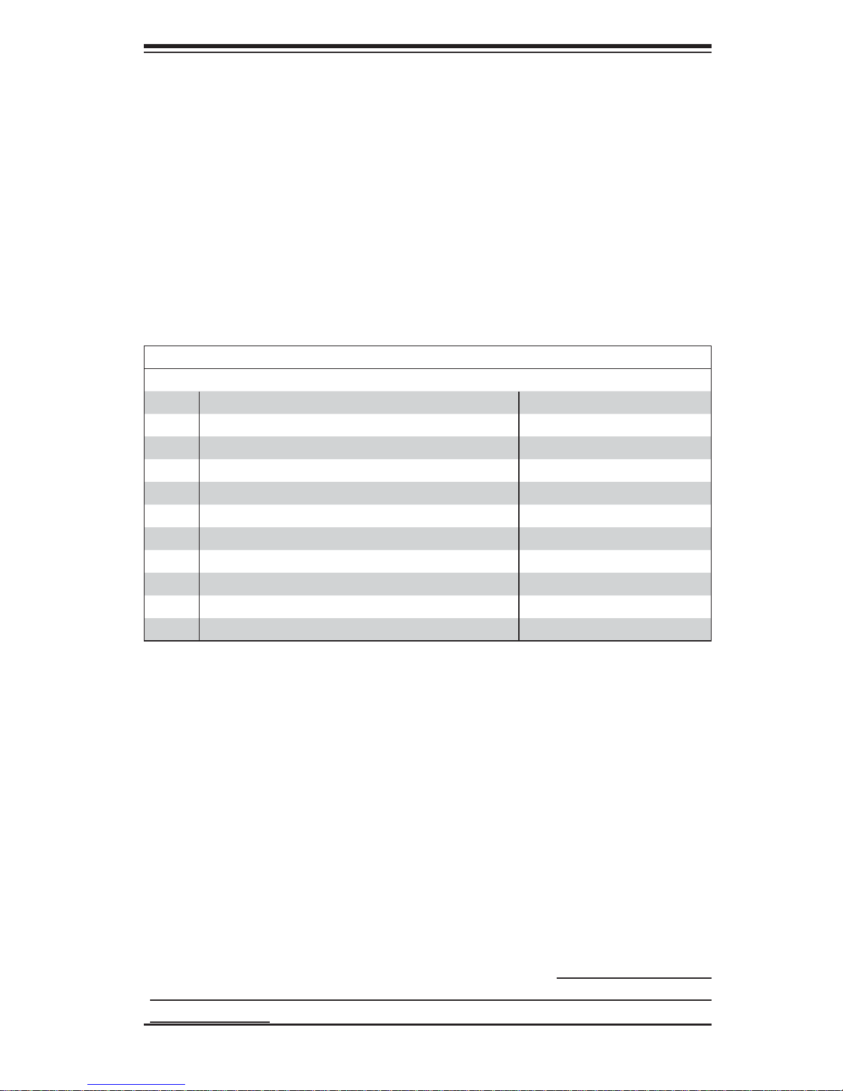
Replacement Parts List
Qty. Defi nition Part Number
1 Black SC732D4 Desktop Chassis w/ 900W Power Supply CSE-732D4-903B
1 Black Lite-On 5.25" HH 24x DVD-RW SATA Drive DVM-LITE-DVDRW24-HBT
5 61-cm SATA Cables CBL-0044L
1 Sandy Bridge 4C E5-1620 3.6G 10M 130W 2011 Processor P4X-UPE51620-SR0LC
1 Motherboard X9SRA
2 4GB DDR3-1600 1.5V 2Rx8 LP ECC REG DIMMs MEM-DR340L-SL02-ER16
1 Seagate 500GB 6Gb/s 7.2k RPM, 3.5" SATA HDD HDD-T0500-ST500NM0011
1 4U Active CPU Heat Sink for X9 Socket R SNK-P0050AP4
1 NVIDIA® C2075 Tesla GPU Card AOC-GPU-NVC2075
1 NVIDIA® Quadro 2000 GPU Card AOC-GPU-NVQ2000
1 Standard I/O Shield for C7P67 with EMI Gasket MCP-260-00046-0N
System Recovery Instructions
This computer includes a hidden partition which contains a backup of your factory
Windows installation. In case of a system failure, you can use this backup to restore
your computer to a working state in just a few minutes.
Since this backup resides on the same physical hard-disk as your current Windows
installation, a hardware failure of the hard-disk will prevent you from reinstalling
Windows. There are two different ways to initiate a system recovery of your system:
• Trigger recovery from OS level (run FullRestore.exe)
• Trigger recovery during system boot up (press F10 key).
Warning: System Recovery will wipe all of your personal data and restore the system
to OOBE. You must have your CD-KEY from COA label ready before performing this
action. System Recovery is an automated, one-step process. Do not initiate a system
recovery unless you are prepared for a complete re-installation back to the factory
default installation.
1-1

SuperWorkstation 5037A-i2-MA015 User's Manual
1-2 Motherboard Features
The SuperWorkstation 5037A-i2-MA015 uses the X9SRA, a single processor motherboard built around the Intel® C600 series chipset. Below are the main features
of the X9SRA.
Processors
The 5037A-i2-MA015 supports an Intel E5-2600/E5-1600 series processor (201 1-pin
Socket R). Please refer to the motherboard description pages on our Web site for
a complete listing of supported processors (www.supermicro.com).
Memory
The 5037A-i2-MA015 features up to 256GB RDIMM or 64GB UDIMM; DDR3 up
to 1600MHz.
SATA
A SATA controller is integrated into the chipset to provide a Serial ATA subsystem.
The 5037A-i2-MA015 supports two SATA 3.0 and eight SATA 2.0 ports.
PCI Expansion Slots
The 5037A-i2-MA015 has the following PCI expansion slots:
Two (2) PCI-Express 3.0 x16 Slot, one (1) PCI-Express 3.0 x4 in x8 Slot, one (1)
PCI-Express 2.0 x4 in x8 Slot and one (1) PCI 33MHz Slot.
Onboard Controllers/Ports
The color-coded I/O ports include eight (8) USB 2.0 ports on the rear I/O panel
Six (6) USB 2.0 headers for front panel access, two (2) USB 3.0 (5Gb/s) headers
for front panel access, two (2) USB 3.0 (5Gb/s) ports on the rear I/O panel PS/2
mouse and keyboard ports, two (2) Fast UART 16550 connections on two headers
(COM1 & COM2). See Figure 1-2.
1-2

Chapter 1: Workstation Overview
1-3 Chassis Features
The 5037A-i2-MA015 is a workstation with Whisper Quiet operation. The following is
a general outline of its main features. See Figure 1-3 for a front view of the chassis.
System Power
The 5037A-i2-MA015 features a single 900W Gold Level multi-outlet power supply
with PMBus, ideal for use in a workstation environment.
SATA Support
The 5037A-i2-MA015 was designed to support four 3.5" SATA hard drives and
four optional 2.5" hard drives.
Front Control Panel
The control panel on the 5037A-i2-MA015 provides you with system monitoring
and control. LEDs indicate system power, HDD activity, network activity, overheat
conditions and power supply failure. A main power button and a system reset button are also included.
Note: The power supply fail LED indicates the power supply fan has failed.
Cooling System
The 5037A-i2-MA015 has an innovative "Whisper Quiet" cooling design that provides suffi cient cooling at very low noise level - ideal for a workplace environment.
The chassis includes one 12-cm exhaust fan located at the rear of the chassis, and
one 12-cm optional system cooling fan in the middle of the chassis.
The power supply has one internal fan for redundancy; if this fan fails, the power
supply must be replaced.
Control Panel
JF1 contains header pins for various front control panel connectors. See Figure 1-1
for the pin locations of the various front control panel buttons and LED indicators.
1-3
SuperWorkstation 5037A-i2-MA015 User's Manual
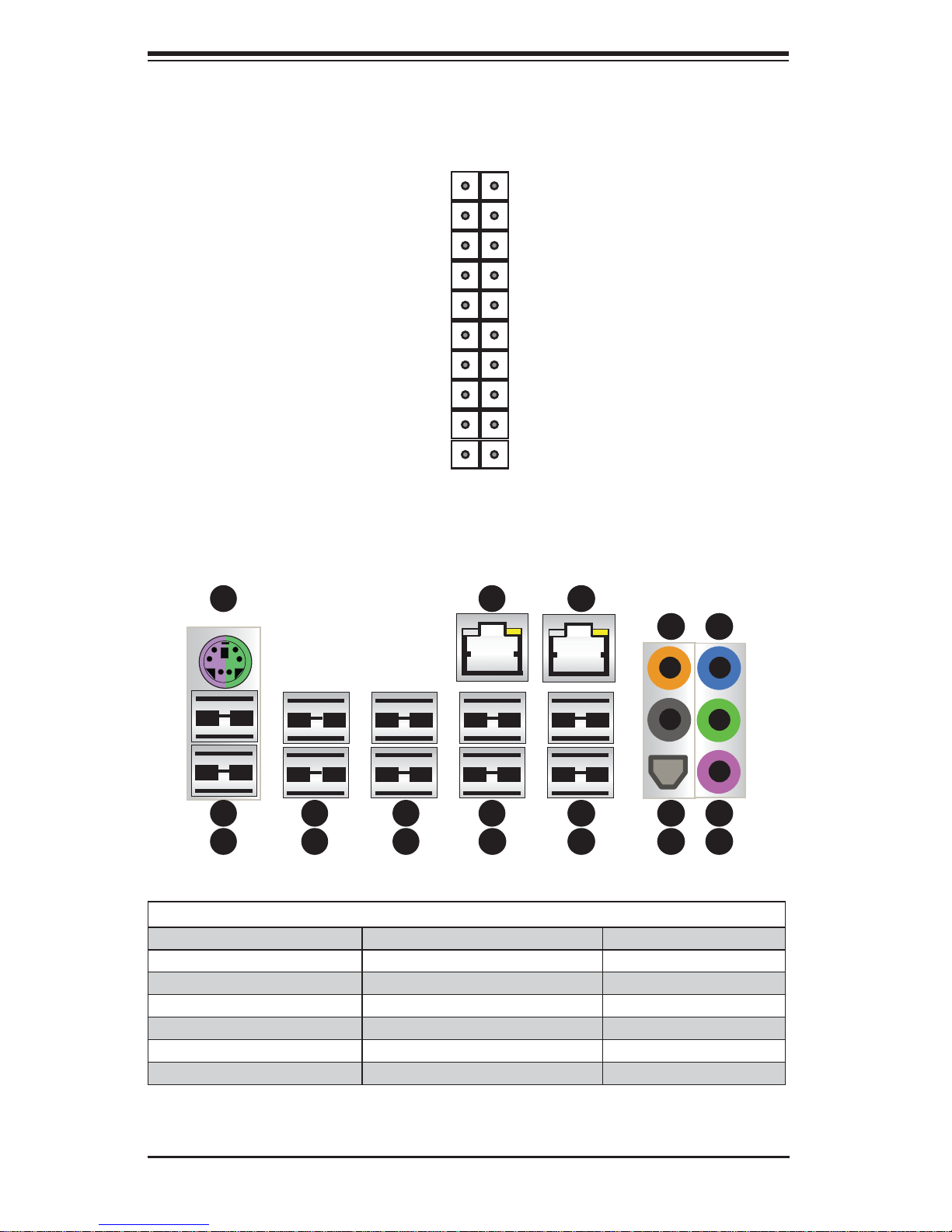
Figure 1-1. Control Panel Header Pins
20 19
Ground
NMI
X .
Power On LED
HDD LED
NIC1 LED
NIC2 LED
OH/Fan Fail LED
Power Fail LED
Ground
Ground
2 1
Figure 1-2. I/O Ports
1
1
X
LED VCC
LED VCC
LED VCC
LED VCC
LED VCC
LED VCC
#3 - 4 Reset Button
#1 - 2 Power Button
8
1
11
1
14
1
17
1
2
1
3
1
1. Keyboard/Mouse 7. USB 2.0 Port 5 13. USB 2.0 Port 7
2. USB 2.0 Port 0 8. LAN 1 Port 14. Center/LFE Out
3. USB 2.0 Port 1 9. USB 3.0 Port 0 15. Surround Out
4. USB 2.0 Port 2 10. USB 3.0 Port 1 16. S/P DIF Out
5. USB 2.0 Port 3 11. LAN 2 Port 17. Line In
6. USB 2.0 Port 4 12. USB 2.0 Port 6 18. Line Out
4
1
5
1
6
1
7
1
I/O Backpanel
9
1
10
1
1-4
12
1
13
1
19. Mic In
15118
1
16119
1
USB Ports
(2x USB 3.0 and
2x USB 2.0)
Chapter 1: Workstation Overview
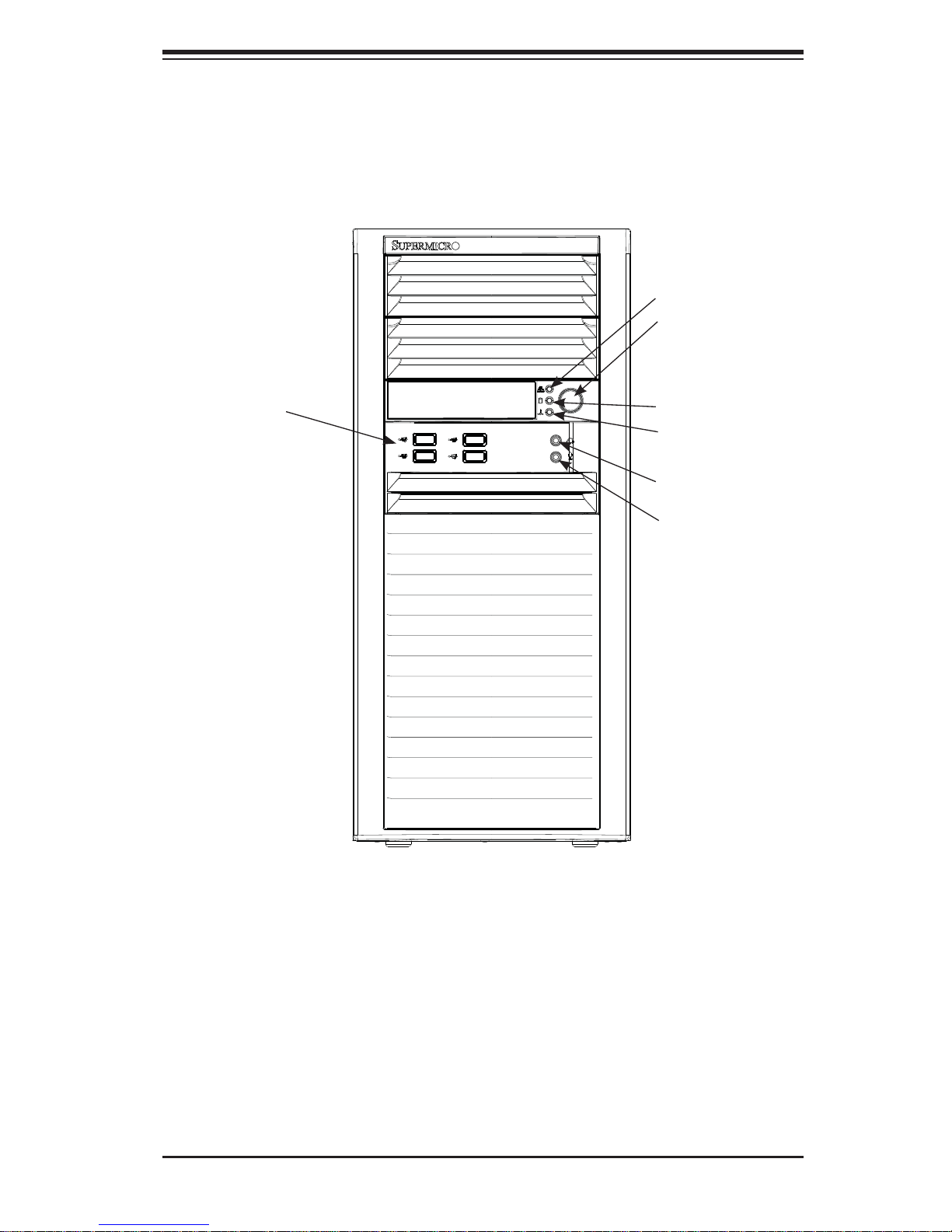
Figure 1-3. Front View of Workstation
LAN Activity LED
Main Power
HDD Activity LED
Overheat/Fan Fail LED
Audio
Microphone
Eight SATA
Drive Bays
(inside chassis)
1-5

SuperWorkstation 5037A-i2-MA015 User's Manual
1-4 Contacting Supermicro
Headquarters
Address: Super Micro Computer, Inc.
980 Rock Ave.
San Jose, CA 95131 U.S.A.
Tel: +1 (408) 503-8000
Fax: +1 (408) 503-8008
Email: marketing@supermicro.com (General Information)
support@supermicro.com (Technical Support)
Web Site: www.supermicro.com
Europe
Address: Super Micro Computer B.V.
Het Sterrenbeeld 28, 5215 ML
's-Hertogenbosch, The Netherlands
Tel: +31 (0) 73-6400390
Fax: +31 (0) 73-6416525
Email: sales@supermicro.nl (General Information)
support@supermicro.nl (Technical Support)
rma@supermicro.nl (Customer Support)
Asia-Pacifi c
Address: Super Micro Computer, Inc.
4F, No. 232-1, Liancheng Rd
New Taipei City 235
Taiwan
Tel: +886-(2) 8226-3990
Fax: +886-(2) 8226-3991
Web Site: www.supermicro.com.tw
Technical Support:
Email: support@supermicro.com.tw
Tel: +886-(2)-8226-3990
1-6

Chapter 2: Workstation Setup
Chapter 2
Workstation Setup
2-1 Unpacking the System
You should inspect the box the system was shipped in and note if it was damaged
in any way. If the system itself shows damage you should fi le a damage claim with
the carrier who delivered it.
Review the warnings and cautions, which may also be found on the Supermicro
Web site at http://www.supermicro.com/about/policies/safety_information.cfm.
2-2 Preparing for Setup
Decide on a suitable location for the workstation. It should be situated in a clean,
dust-free area that is well ventilated. Avoid areas where heat, electrical noise and
electromagnetic fi elds are generated. You will also need it placed near a grounded
AC power outlet.
Setting Up
1. Locate the workstation is a suitable area according to the guidelines above.
2. Connect the mouse, keyboard and monitor to the workstation.
3. Connect an Ethernet cable to a LAN port if needed.
4. Connect the power to the power supply and then to a grounded AC outlet.
2-1
SuperWorkstation 5037A-i2-MA015 User's Manual
COM2
USB8/9
3-SGPIO1
3-SGPIO2
JPI2C1
JPW2
USB 0/1
JKBMS1
JPME1
T-SGPIO2
T-SGPIO1
USB 2/3
AUDIO FP
COM1
USB10/11
USB12/13
I-SATA1
I-SATA0
I-SATA3
I-SATA2
I-SATA4
I-SATA5
JWF1
JCF1
JOH1
FANA
JUSB 2/3
FAN 3
JF1
JPT1
JTPM1
JWD1
JD1
FAN 2
FAN 1
JPW1
USB 6/7
USB3.0 0/1
USB 4/5
LAN1
LAN2
HD AUDIO
FAN 5
FAN 4
JPUSB1
JPL2
JSPDIF OUT
JSPDIF IN
JI2C1
JI2C2
JSTBY
JPAC1
JBT1
JL1
DP2
SLOT1
SLOT2
SLOT3
SLOT4
SLOT6
DIMM SLOTS
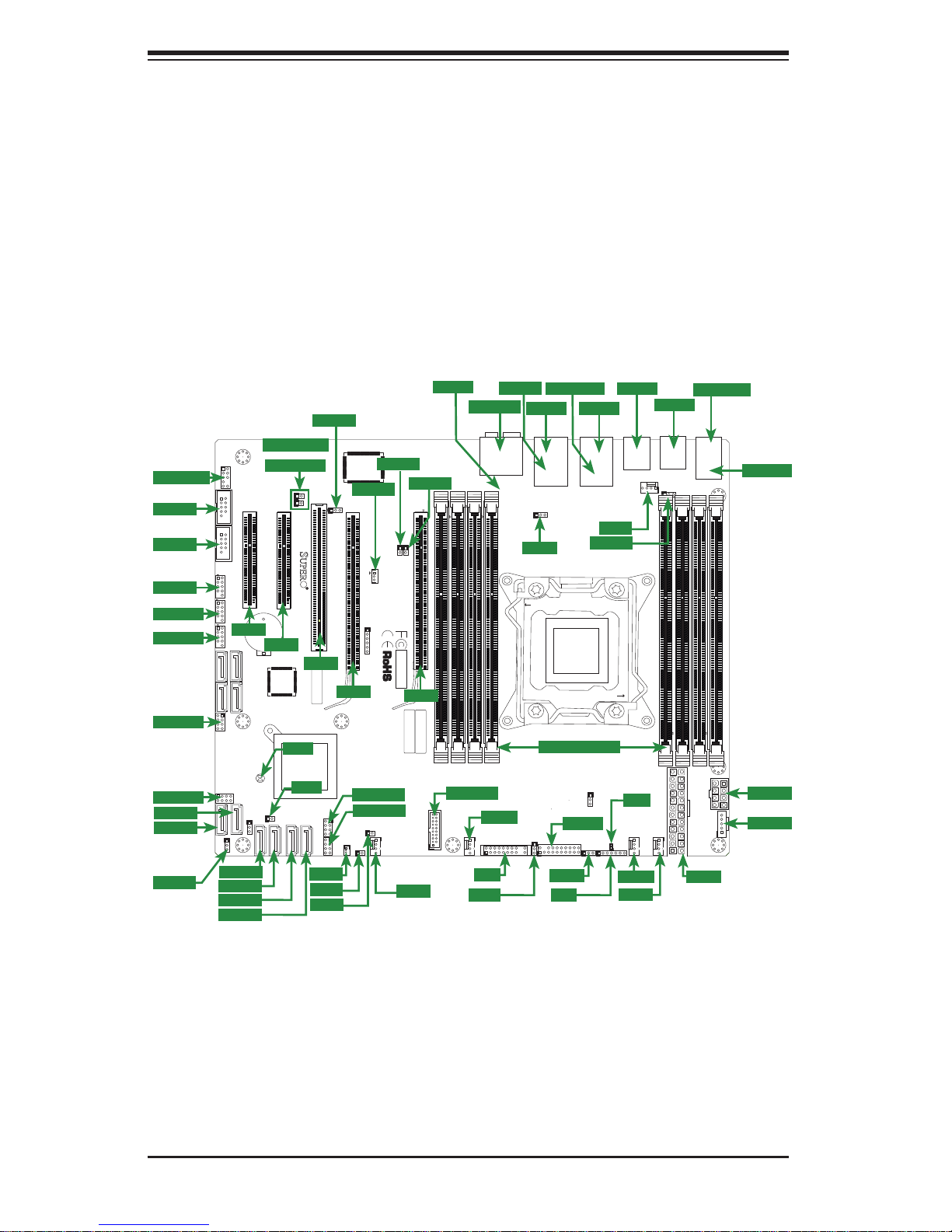
2-3 Motherboard Layout
This section provides details on the motherboard and jumper settings that may be
useful when setting up the system.
Figure 2-1. Layout
AUDIO FP
COM2
COM1
USB8/9
USB10/11
USB12/13
3-SGPIO1
3-SGPIO2
I-SATA1
I-SATA0
JPME1
JFPAUDIO
AUDIO FP
21
9
JCOM2
156
COM2
OFF:By BIOS
JFPAUDIO_EN1
ON:Force Enable
JCOM1
USB8/9
JUSB89
1
USB10/11
JUSB1011
7
1
USB12/13
SLOT1
JUSB1213
3-SGPIO1
3-SGPIO2
JPME1
MH3
31
I-SATA2
I-SATA3
I-SATA4
I-SATA5
MH1
COM1
SAS0
SAS1
SAS2
SAS3
JPBIOS1
1-2:BIOS recovery
2-3:Normal
MH6
I-SATA1
I-SATA0
JPME_DBG
PCIE1
JBT1
JSPDIF OUT
JSPDIF IN
1
1
PCIE2
SLOT2 PCI-E 3.0 X4(IN X8)
SLOT1 PCI-E 2.0 X4(IN X8)
DESIGNED IN USA
SLOT2
BT1
+
JRK1
Pin1:RAID_KEY_PCH
Pin2:Ground
Pin3:PCH_DYN_SKU
H*
JBT1
JL1
JPME_DBG
1-2:ME Debug
2-3:Normal
JL1
I-SATA3
JPME1
1-2:ME recovery
2-3:Normal
1
CHASSIS
I-SATA2
INTRUSION
I-SATA4
JPAC1
JPAC1:AUDIO
1-2:ENABLE
2-3:DISABLE
JSPDIF_OUT
JSPDIF_IN
JPCI3
SAS CODE
SLOT3
T-SGPIO2
I-SATA5
T-SGPIO1
JWF1
JCF1
JOH1
JPAC1
SLOT3 PCI 33MHZ
SLOT4
MH5
JSTBY
SLOT4 PCI-E 3.0 X16
B81
B82
A81
A82
T-SGPIO2
T-SGPIO1
Compact
Flash
Power
1
JWF1
JCF1
3
1
PCIE4
JSTBY
1
Wake on Lan
3
1
6
JTAG1
JOH1
1
FANA
4
JI2C1
SLOT5 PCI-E 2.0 X1
1
JI2C1
JI2C2
I2C bus for PCI slot
JI2C1/JI2C2
OFF:DISABLE
ON: ENABLE
X9SRA
REV:1.01
Tested to Comply
With FCC Standards
FOR HOME OR OFFICE USE
SLOT6
FANA
JI2C2
PCIE6
1
SLOT6 PCI-E 3.0 X16
BAR CODE
MAC
JUSB1617
FAN 5
DIMM1A
JCF1:Compact Flash
ON: MASTER
OFF: SLAVE
JUSB 2/3
USB3.0 2/3
MH7
HD AUDIO
JAUDIO1
HD AUDIO
DIMM1B
DIMM2A
DIMM2B
FAN 3
FAN3
JF1
JF1
JPT1
USB 6/7
LAN2
USB6/7
JPL2
JPL2
CLOSE 1st
FAIL
PWR
RSTONPWR
NIC
NICOHLED
FF
1
2
JPT1
1-2:ENABLE
2-3:DISABLE
JPTM1
:TPM/PRO80
USB3.0 0/1
LAN1
JLAN2_USB67
LAN1
LAN2
JPUSB1
OPEN 1st
CPU1
DIMM SLOTS
JF1
HDD
PWR
NMI
X
JVR2
JTPM1
JWD1
JWD1
JD1
USB 4/5
USB3.0 0/1
FAN 4
DP2
FAN4
DP2
JWD1:Watch Dog
1-2:RST
2-3:NMI
FAN2
JD1
FAN 2
FAN 1
USB4/5
JUSB45
DIMM4B
USB 2/3
USB2/3
JPUSB1
DIMM4A
JD1:
PWR LED
1-3:
SPEAKER
4-7:
FAN1
JUSB23
JKBMS_USB01
JPW1
JPW1
JKBMS1
KB/MOUSE
USB0/1
1-2 ENable
2-3 Disable
JPUSB1:USB Wake Up
MH9
DIMM3A
DIMM3B
MH4
JPW2
JPI2C1
1
PWRI2C
MH8
USB 0/1
JPW2
JPI2C1
2-2
Chapter 2: Workstation Setup
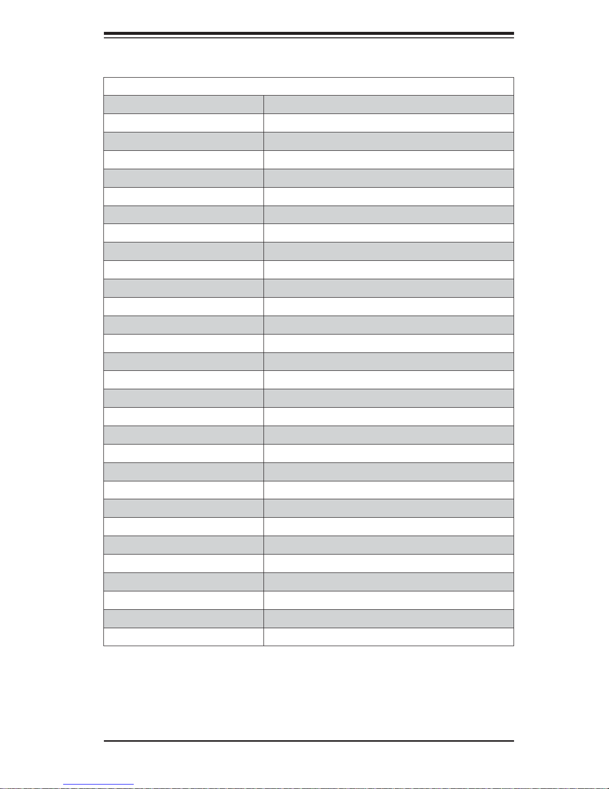
Motherboard Headers/Connectors
Connector Description
AUDIO FP Front Panel Audio Header
COM1, COM2 COM1 & COM2 Serial Port Headers
USB 8/9, USB 10/11, USB 12/13 USB 2.0 Headers for front panel access
JUSB2/3 (USB 3.0) USB 3.0 Header for USB 2/3
USB 0/1, USB 2/3, USB 4/5, USB 6/7 Back Panel USB 2.0 Ports
USB 3.0 0/1 Back Panel USB 3.0 Ports
JKBMS1 Combination PS/2 Keyboard/Mouse Port
LAN1, LAN2 Gb Ethernet LAN Ports (LAN1 & LAN2)
HD Audio High Defi nition (HD) Audio output jacks
JSPDIF OUT/IN SP/DIF Audion In/Out Headers
3-SGPIO1, 3-SGPIO2 Serial General Purpose I/O Headers for SAS
I-SATA0, I-SATA1 Serial ATA ports (SATA 3.0), 6Gb/s
I-SATA2~5 Serial ATA ports (SATA 2.0), 3Gb/s
JWF1 SATA DOM (Disk On Module) Power Connector
JOH1 O verhe at LED/Fan Fai l
FAN A, FAN1~FAN4 Internal Fan Headers
JF1 Front Panel Control Header
JTPM1 Trusted Platform Module (TPM) Header
JD1 Power LED / Speaker Header (Pins 4~7: External Speaker)
T-SGPIO1, T-SGPIO2 Serial Link General Purpose I/O Headers (5V Gen1/Gen 2)
JPW1 24-pin Main ATX Power Connector
JPW2 8-pin Secondary Power Connector
JPI2C1 Power Supply SMBus I2C Header
JL1 Chassis Intrusion Header
JSTBY Legacy Wake On LAN Header
SLOT1 PCI-E 2.0 x4 (in x8 Slot)
SLOT2 PCI-E 3.0 x4 (in x8 Slot)
SLOT3, PCI 33MHz Slot
SLOT4, SLOT6 PCI-E 3.0 x16 Slots
2-3
 Loading...