

Supero SuperWorkstation 7047GR-TRF User Manual
SUPER
SuperWorkstation
7047GR-TRF
®
USER’S MANUAL
Revision 1.0a

The information in this User’s Manual has been carefully reviewed and is believed to be accurate.
The vendor assumes no responsibility for any inaccuracies that may be contained in this document,
makes no commitment to update or to keep current the information in this manual, or to notify any
person or organization of the updates. Please Note: For the most up-to-date version of this
manual, please see our web site at www.supermicro.com.
Super Micro Computer, Inc. ("Supermicro") reserves the right to make changes to the product
described in this manual at any time and without notice. This product, including software and
documentation, is the property of Supermicro and/or its licensors, and is supplied only under a
license. Any use or reproduction of this product is not allowed, except as expressly permitted by
the terms of said license.
IN NO EVENT WILL SUPERMICRO BE LIABLE FOR DIRECT, INDIRECT, SPECIAL, INCIDENTAL,
SPECULATIVE OR CONSEQUENTIAL DAMAGES ARISING FROM THE USE OR INABILITY TO
USE THIS PRODUCT OR DOCUMENTATION, EVEN IF ADVISED OF THE POSSIBILITY OF
SUCH DAMAGES. IN PARTICULAR, SUPERMICRO SHALL NOT HAVE LIABILITY FOR ANY
HARDWARE, SOFTWARE, OR DATA STORED OR USED WITH THE PRODUCT, INCLUDING THE
COSTS OF REPAIRING, REPLACING, INTEGRATING, INSTALLING OR RECOVERING SUCH
HARDWARE, SOFTWARE, OR DATA.
Any disputes arising between manufacturer and customer shall be governed by the laws of Santa
Clara County in the State of California, USA. The State of California, County of Santa Clara shall
be the exclusive venue for the resolution of any such disputes. Super Micro's total liability for all
claims will not exceed the price paid for the hardware product.
FCC Statement: This equipment has been tested and found to comply with the limits for a class B
digital device, pursuant to Part 15 of the FCC Rules. These limits are designed to provide reasonable
protection against harmful interference in a residential installation. This equipment generates,
uses, and can radiate radio frequency energy and, if not installed and used in accordance with
the instructions, may cause harmful interference to radio communications. However, there is no
guarantee that interference will not occur in a particular installation. If this equipment does cause
harmful interference to radio or television reception, which can be determined by turning the
equipment off and on, the user is encouraged to try to correct the interference by one or more of
the following measures:
• Reorient or relocate the receiving antenna.
• Increase the separation between the equipment and receiver.
• Connect the equipment to an outlet on a circuit different from that to which the receiver
is connected.
• Consult the authorized dealer or an experienced radio/TV technician for help.
California Best Management Practices Regulations for Perchlorate Materials: This Perchlorate
warning applies only to products containing CR (Manganese Dioxide) Lithium coin cells. “Perchlorate
Material-special handling may apply. See www.dtsc.ca.gov/hazardouswaste/perchlorate”
WARNING: Handling of lead solder materials used in this
product may expose you to lead, a chemical known to
the State of California to cause birth defects and other
reproductive harm.
Manual Revision 1.0a
Release Date: December 10, 2012
Unless you request and receive written permission from Super Micro Computer, Inc., you may not
copy any part of this document.
Information in this document is subject to change without notice. Other products and companies
referred to herein are trademarks or registered trademarks of their respective companies or mark
holders.
Copyright © 2012 by Super Micro Computer, Inc.
All rights reserved.
Printed in the United States of America

Preface
About This Manual
This manual is written for professional system integrators and PC technicians. It
provides information for the installation and use of the SuperWorkstation 7047GRTRF. Installation and maintenance should be performed by experienced technicians
only.
The SuperWorkstation 7047GR-TRF is based on the SC747TQ-R1620B 4U/Tower
rackmount chassis and the Super X9DRG-QF serverboard. Please refer to our web
site for an up-to-date list of supported operating systems, processors and memory.
Manual Organization
Preface
Chapter 1: Introduction
The fi rst chapter provides a checklist of the main components included with the
workstation system and describes the main features of the Super X9DRG-QF
serverboard and the SC747TQ-R1620B chassis.
Chapter 2: Workstation Installation
This chapter describes the steps necessary to install the system into a rack and
check out the workstation confi guration prior to powering up the system. If your
workstation was ordered without the processor and memory components, this
chapter will refer you to the appropriate sections of the manual for their installation.
Chapter 3: System Interface
Refer to this chapter for details on the system interface, which includes the functions
and information provided by the control panel on the chassis as well as other LEDs
located throughout the system.
Chapter 4: System Safety
You should thoroughly familiarize yourself with this chapter for a general overview
of safety precautions that should be followed when installing and servicing the
system.
Chapter 5: Advanced Serverboard Setup
Chapter 5 provides detailed information on the X9DRG-QF serverboard, including
the locations and functions of connectors, headers and jumpers. Refer to
iii

SUPERWORKSTATION 7047GR-TRF User's Manual
this chapter when adding or removing processors or main memory and when
reconfi guring the serverboard.
Chapter 6: Advanced Chassis Setup
Refer to Chapter 6 for detailed information on the SC747TQ-R1620B 4U/Tower
rackmount chassis. You should follow the procedures given in this chapter when
installing, removing or reconfi guring Serial ATA or peripheral drives and when
replacing system power supply units and cooling fans.
Chapter 7: BIOS
The BIOS chapter includes an introduction to BIOS and provides detailed information
on running the CMOS Setup Utility.
Appendix A: BIOS Beep Codes
Appendix B: System Specifi cations
iv

Notes
Preface
v

SUPERWORKSTATION 7047GR-TRF User's Manual
Table of Contents
Chapter 1 Introduction
1-1 Overview ......................................................................................................... 1-1
1-2 Serverboard Features ..................................................................................... 1-2
Processors ...................................................................................................... 1-2
Memory ........................................................................................................... 1-2
Serial ATA ....................................................................................................... 1-2
PCI Expansion Slots ....................................................................................... 1-2
Rear I/O Ports ................................................................................................. 1-2
IPMI ................................................................................................................. 1-2
1-3 Chassis Features ............................................................................................ 1-3
System Power ................................................................................................. 1-3
Mounting Rails (optional) ................................................................................ 1-3
Hard Drive/Drive Bays .................................................................................... 1-3
Control Panel .................................................................................................. 1-3
Cooling System ............................................................................................... 1-3
1-5 Contacting Supermicro .................................................................................... 1-5
Chapter 2 Workstation Installation
2-1 Overview ......................................................................................................... 2-1
2-2 Unpacking the System .................................................................................... 2-1
2-3 Preparing for Setup ......................................................................................... 2-1
Choosing a Setup Location ............................................................................. 2-1
2-4 Warnings and Precautions! ............................................................................. 2-2
Rack Precautions ............................................................................................ 2-2
Workstation Precautions ................................................................................. 2-2
Rack Mounting Considerations ....................................................................... 2-3
Ambient Operating Temperature ................................................................ 2-3
Reduced Airfl ow ......................................................................................... 2-3
Mechanical Loading ................................................................................... 2-3
Circuit Overloading ..................................................................................... 2-3
Reliable Ground ......................................................................................... 2-3
2-4 Installing the Chassis onto a Rack ................................................................. 2-3
Removing the Chassis Cover and Feet .......................................................... 2-4
Identifying the Sections of the Rack Rails ...................................................... 2-4
Installing the Chassis Handles and Inner Rails .............................................. 2-6
Installing the Outer Rails to the Rack ............................................................. 2-7
Installing the Chassis into a Rack................................................................... 2-8
2-5 Tower Mounting Instructions ........................................................................... 2-9
vi

Table of Contents
Installing the Chassis Cover ........................................................................... 2-9
Installing Feet on the Chassis ...................................................................... 2-10
Chapter 3 System Interface
3-1 Overview ......................................................................................................... 3-1
3-2 Control Panel Buttons ..................................................................................... 3-2
3-3 Control Panel LEDs ........................................................................................ 3-2
3-4 Drive Carrier LEDs .......................................................................................... 3-4
Chapter 4 Standardized Warning Statements for AC Systems
4-1 About Standardized Warning Statements ....................................................... 4-1
Warning Defi nition ........................................................................................... 4-1
Installation Instructions .................................................................................... 4-4
Circuit Breaker ................................................................................................ 4-5
Power Disconnection Warning ........................................................................ 4-6
Equipment Installation ..................................................................................... 4-8
Restricted Area ................................................................................................ 4-9
Battery Handling ............................................................................................ 4-10
Redundant Power Supplies .......................................................................... 4-12
Backplane Voltage ........................................................................................ 4-13
Comply with Local and National Electrical Codes ........................................ 4-14
Product Disposal ........................................................................................... 4-15
Hot Swap Fan Warning ................................................................................. 4-16
Power Cable and AC Adapter ...................................................................... 4-18
Chapter 5 Advanced Serverboard Setup
5-1 Handling the Serverboard ............................................................................... 5-1
Precautions ..................................................................................................... 5-1
Unpacking ....................................................................................................... 5-2
5-2 Connecting Cables .......................................................................................... 5-2
Connecting Data Cables ................................................................................. 5-2
Connecting Power Cables .............................................................................. 5-2
Connecting the Control Panel ......................................................................... 5-2
5-3 I/O Ports .......................................................................................................... 5-3
5-4 Installing the Processor and Heatsink ............................................................ 5-4
Installing an LGA2011 Processor .................................................................... 5-4
Installing the Heatsink ..................................................................................... 5-6
Removing the Heatsink ................................................................................... 5-7
5-6 Installing Memory ............................................................................................ 5-8
5-6 Adding PCI Add-On Cards ............................................................................ 5-12
5-7 Serverboard Details ...................................................................................... 5-13
X9DRG-QF Quick Reference ........................................................................ 5-13
vii

SUPERWORKSTATION 7047GR-TRF User's Manual
5-8 Connector Defi nitions ................................................................................... 5-15
5-9 Jumper Settings ............................................................................................ 5-22
5-10 Onboard Indicators ........................................................................................ 5-24
5-11 SATA Ports .................................................................................................... 5-25
5-12 Installing Software ......................................................................................... 5-26
Supero Doctor III ........................................................................................... 5-27
Chapter 6 Advanced Chassis Setup
6-1 Static-Sensitive Devices .................................................................................. 6-2
Precautions ..................................................................................................... 6-2
6-2 Control Panel .................................................................................................. 6-2
6-3 System Cooling ............................................................................................... 6-3
System Fan Failure ......................................................................................... 6-3
Replacing System Fans .................................................................................. 6-3
6-4 Power Supply .................................................................................................. 6-5
Power Supply Failure ...................................................................................... 6-5
Replacing the Power Supply ........................................................................... 6-5
Power Supply Connections ............................................................................. 6-6
6-5 Confi guring the Storage Module .................................................................... 6-7
Tower or Rack Confi guration........................................................................... 6-7
Rotating the Storage Module .......................................................................... 6-8
Installing Drives in the Storage Module .......................................................... 6-9
Removing a Drive Carrier ............................................................................. 6-10
Adding Peripheral Drives .............................................................................. 6-12
6-6 Installing Hard Drives in the Chassis ............................................................ 6-13
Chapter 7 BIOS
7-1 Introduction ...................................................................................................... 7-1
7-2 Main Setup ...................................................................................................... 7-2
7-3 Advanced Setup Confi gurations...................................................................... 7-4
7-4 Event Logs .................................................................................................... 7-25
7-5 IPMI ............................................................................................................... 7-27
7-6 Boot ............................................................................................................... 7-29
7-7 Security ......................................................................................................... 7-30
7-8 Save & Exit ................................................................................................... 7-31
Appendix A BIOS Error Beep Codes
Appendix B System Specifi cations
viii

Chapter 1: Introduction
Chapter 1
Introduction
1-1 Overview
The SuperWorkstation 7047GR-TRF is comprised of two main subsystems: the
SC747TQ-R1620B 4U/Tower chassis and the X9DRG-QF dual Intel Xeon processor
serverboard. Please refer to our web site for information on operating systems that
have been certifi ed for use with the system (www.supermicro.com).
In addition to the serverboard and chassis, various hardware components have
been included with the workstation, as listed below:
• Two 38 mm 4-pin PWM fan assemblies (FAN-0082L4)
• Four 92 x 38 mm 4-pin PWM fan assemblies (FAN-0114L4)
• Two 4U active CPU heatsinks (SNK-P0050AP4)
• SATA accessories:
One HD backplane (BPN-SAS-747TQ)
Eight 3.5" hard disk drive trays (MCP-220-00094-0B)
Three 5.25" drive trays (MCP-220-00073-0B)
• One SuperWorkstation 7047GR-TRF User's Manual
• One Supermicro CD containing drivers and utilities
Optional
• One 4U 17.2" width rack rail set (MCP-290-00059-0N)
Note: a complete list of safety warnings is provided on the Supermicro web site at
http://www.supermicro.com/about/policies/safety_information.cfm
1-1

SUPERWORKSTATION 7047GR-TRF User's Manual
1-2 Serverboard Features
At the heart of the SuperWorkstation 7047GR-TRF lies the X9DRG-QF, a dual
processor serverboard based on the Intel C602 chipset. Below are the main features
of the X9DRG-QF. (See Figure 1-1 for a block diagram of the chipset).
Processors
The X9DRG-QF supports two Intel® E5-2600 Series processors in LGA 2011 sockets
(Socket R). Please refer to the serverboard description pages on our web site for a
complete listing of supported processors (www.supermicro.com).
Memory
The X9DRG-QF has sixteen DIMM slots that can support up to 512 GB of DDR31600/1333/1066/800 RDIMM, LRDIMM or UDIMM ECC/non-ECC memory. Modules
of the same size and speed are recommended. See Chapter 5 for details.
Serial ATA
A SATA controller is integrated into the chipset to provide a ten-port SATA
subsystem, which is RAID 0, 1, 5 and 10 supported. the I-SATA 0-1 ports are SATA
3.0 ports. The I-SATA2-5 ports and the S-SATA0-3 ports are SATA 2.0 ports. The
SATA drives are hot-swappable units.
Note: The operating system you use must have RAID support to enable the hotswap capability and RAID function of the Serial ATA drives.
PCI Expansion Slots
The X9DRG-QF has four PCI-E 3.0 x16, two PCI-E 3.0 x8 (1 in x16) and one PCI-E
2.0 x4 (in x8) slots for a total of seven PCI expansion slots.
Rear I/O Ports
The color-coded I/O ports include one COM port, a VGA (monitor) port, four USB
2.0 ports, a dedicated IPMI LAN port and two Gb Ethernet LAN ports.
IPMI
IPMI (Intelligent Platform Management Interface) is a hardware-level interface
specifi cation that provides remote access, monitoring and administration for
Supermicro workstation platforms. IPMI allows administrators to view a workstation’s
hardware status remotely, receive an alarm automatically if a failure occurs, and
power cycle a system that is non-responsive.
1-2

Chapter 1: Introduction
1-3 Chassis Features
The following is a general outline of the main features of the SC747TQ-R1620B
chassis.
System Power
The SC747TQ-R1620B chassis includes a 1620W high-effi ciency, redundant (1+1)
power supply consisting of two power supply modules. In the unlikely event a power
supply module fails, replacement is simple and can be done without tools. The AC
power cord should be removed from the system before servicing or replacing a
power supply module. See Chapter 6 for details.
Mounting Rails (optional)
The SC747 can be placed in a rack for secure storage and use. To setup your rack,
follow the step-by-step instructions included in this manual in Chapter 2.
Hard Drive/Drive Bays
The SC747 chassis features eight drive bays for SATA drives. These drives are hot
-swappable. Once set up correctly, these drives can be removed without powering
down the workstation.
The SC747 chassis also provides three 5.25” peripheral drive bays for fl oppy drives,
DVD-ROM/CD-ROM drives, or additional hard drives.
Control Panel
The control panel on the workstation provides you with system monitoring and
control. LEDs indicate system power, HDD activity, network activity, system
overheat, UID and power supply failure. A main power button and a system reset
button are also included.
Cooling System
The SC747 chassis accepts four system fans and two rear exhaust fans. System
fans are powered from the serverboard. These fans are 4U high and are powered
by 4-pin connectors.
1-3
SUPERWORKSTATION 7047GR-TRF User's Manual
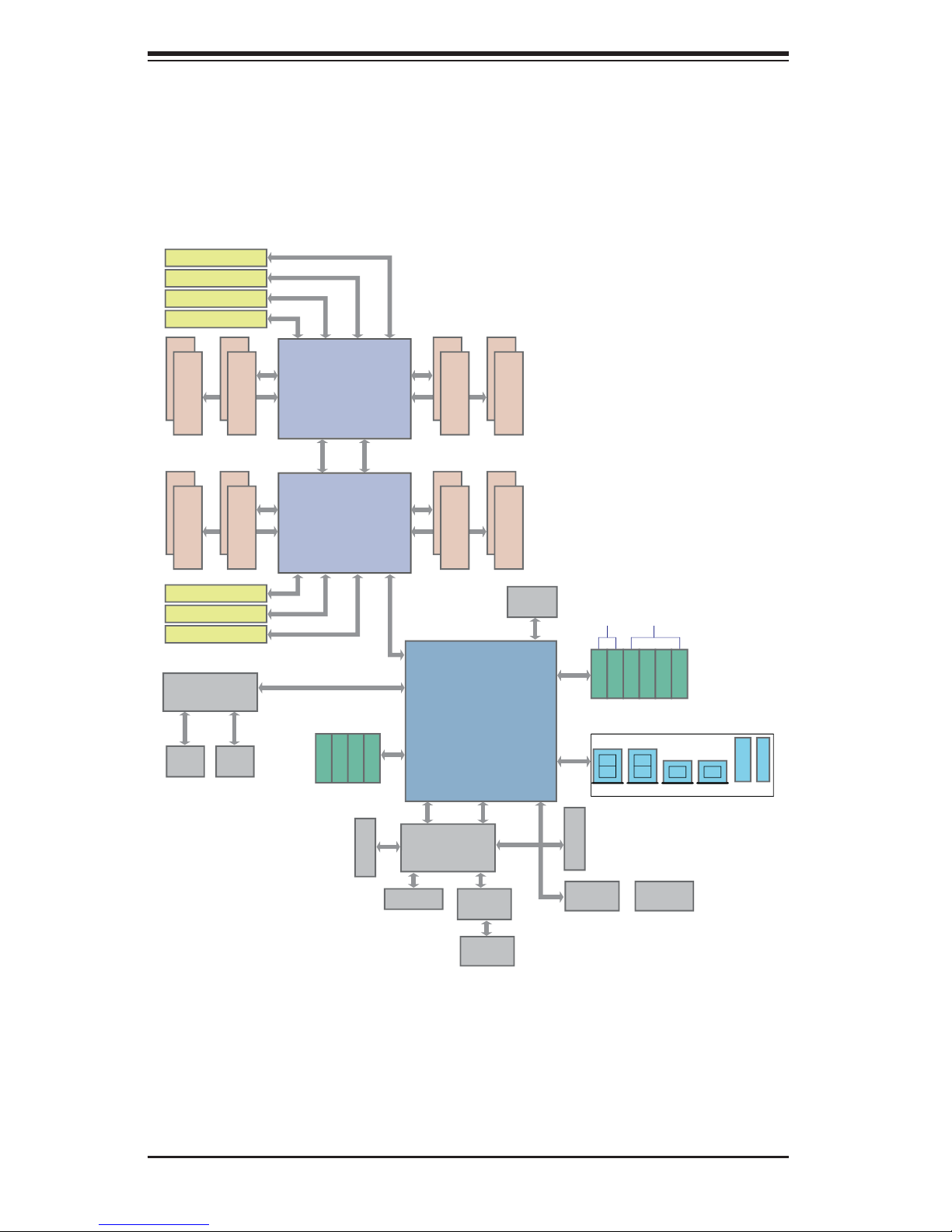
Figure 1-1. Intel C602 Chipset:
System Block Diagram
Note: This is a general block diagram. Please see Chapter 5 for details.
JPEIC11 PCIE3.0 x8
JPEIC9 PCIE3.0 x8
JPEIC8 PCIE3.0 x16
JPEIC6 PCIE3.0 x16
#1
#2
#1
#2
JPEIC4 PCIE3.0 x16
JPEIC2 PCIE3.0 x16
JPEIC10 PCIE3.0 x16
Powerville Dual GbE
I350AM2
JLAN1
RJ45
#1
E
DDR3 DIMM
#1
C
DDR3 DIMM
UL1
JLAN2
RJ45
#2
P00_P11
LANE Reversal
#2
x4
x8
x16
x16
PE3
F
DDR3 DIMM
D
DDR3 DIMM
PE3
x16
x16
x8
PE2 PE1 DMI
CPU REAR
U7C1 Socket 01
Processor
Sandybridge
P0
P1
QPI
QPI
P1 P0
CPU REAR
U6H1 Socket 00
Sandybridge
PE2 PE1 DMI
I-SATA7
I-SATA8
I-SATA9
SAS2/SATA Gen3
6Gbps
H
B
DMI: LANE Reversal
DMI
PEG [0..3]
SATA Gen3 [0..3]
I-SATA6
PET8 USB [10,11]
x1
VGA
DDR3 RAM
VGA CONN
#1
#2
G
DDR3 DIMM
#1
#2
A
DDR3 DIMM
SSB
PATSBURG-A
UM1
RENESAS
BMC
PHY
RTL8211E
#1
#2
DDR3 DIMM
#1
#2
DDR3 DIMM
BIOS
SPI Flash
SATA [0..5]
PET [1..7]
USB [0..9]
SPI
LPC
REAR
TPM Header
Super I/O
W83527
SATA Gen3
6Gbps
SATA Gen2
I-SATA0
I-SATA1
I-SATA2
I-SATA3
0,1
2,3
REAR TYPE A TYPE A
HW Monitor
NCT7904D
3Gbps
I-SATA4
I-SATA5
port 4 port 5
HDR 2X5
HDR 2X5
6,7 8,9
IPMI LAN
RJ45
1-4

1-5 Contacting Supermicro
Headquarters
Address: Super Micro Computer, Inc.
980 Rock Ave.
San Jose, CA 95131 U.S.A.
Tel: +1 (408) 503-8000
Fax: +1 (408) 503-8008
Email: marketing@supermicro.com (General Information)
support@supermicro.com (Technical Support)
Chapter 1: Introduction
Web Site:
Europe
Address: Super Micro Computer B.V.
Tel: +31 (0) 73-6400390
Fax: +31 (0) 73-6416525
Email: sales@supermicro.nl (General Information)
Asia-Pacifi c
Address: Super Micro Computer, Inc.
www.supermicro.com
Het Sterrenbeeld 28, 5215 ML
's-Hertogenbosch, The Netherlands
support@supermicro.nl (Technical Support)
rma@supermicro.nl (Customer Support)
4F, No. 232-1, Liancheng Rd
Chung-Ho Dist., New Taipei City 235
Taiwan
Tel: +886-(2) 8226-3990
Fax: +886-(2) 8226-3991
Web Site:
Technical Support:
Email: support@supermicro.com.tw
Tel: +886-(2)-8226-3990
www.supermicro.com.tw
1-5

SUPERWORKSTATION 7047GR-TRF User's Manual
Notes
1-6

Chapter 2: Workstation Installation
Chapter 2
Workstation Installation
2-1 Overview
This chapter provides a quick setup checklist to get your SuperWorkstation 7047GRTRF up and running. Following the steps in the order given should enable you to
have the system operational within a minimal amount of time. If your system is not
already fully integrated with a motherboard, processor, system memory etc., please
turn to the chapter or section noted in each step for details on installing specifi c
components.
2-2 Unpacking the System
You should inspect the box the SuperWorkstation 7047GR-TRF was shipped in
and note if it was damaged in any way. If the workstation itself shows damage, you
should fi le a damage claim with the carrier who delivered it.
Decide on a suitable location for setting up and operating the SuperWorkstation
7047GR-TRF. It should be situated in a clean, dust-free area that is well ventilated.
Avoid areas where heat, electrical noise and electromagnetic fi elds are generated.
You will also need it placed near a grounded power outlet.
2-3 Preparing for Setup
The box your workstation was shipped in may include two sets of rail assemblies,
two rail mounting brackets and the mounting screws needed to install the system
into the rack (optional parts). Please read this section in its entirety before you begin
the installation procedure outlined in the sections that follow.
Choosing a Setup Location
• Leave enough clearance in front of the rack to enable you to open the front
door completely (~25 inches).
• Leave approximately 30 inches of clearance in the back of the rack to allow for
suffi cient airfl ow and ease in servicing.
2-1

SUPERWORKSTATION 7047GR-TRF User's Manual
• This product is for installation only in a Restricted Access Location (dedicated
equipment rooms, service closets and the like).
2-4 Warnings and Precautions!
Rack Precautions
• Ensure that the leveling jacks on the bottom of the rack are fully extended to
the fl oor with the full weight of the rack resting on them.
• In single rack installation, stabilizers should be attached to the rack. In multiple
rack installations, the racks should be coupled together.
• Always make sure the rack is stable before extending a component from the
rack.
• You should extend only one component at a time - extending two or more si-
multaneously may cause the rack to become unstable.
• Rack-mounted equipment should not be used as a shelf or work space.
Workstation Precautions
• Review the electrical and general safety precautions in Chapter 4.
• Determine the placement of each component in the rack before you install the
rails.
• Install the heaviest workstation components on the bottom of the rack fi rst, and
then work up.
• Use a regulating uninterruptible power supply (UPS) to protect the workstation
from power surges, voltage spikes and to keep your system operating in case
of a power failure.
• Allow the hot plug SATA drives and power supply modules to cool before touch-
ing them.
• Always keep the rack's front door and all panels and components on the work-
stations closed when not servicing to maintain proper cooling.
2-2

Chapter 2: Workstation Installation
Rack Mounting Considerations
Ambient Operating Temperature
If installed in a closed or multi-unit rack assembly, the ambient operating temperature of the rack environment may be greater than the ambient temperature of the
room. Therefore, consideration should be given to installing the equipment in an
environment compatible with the manufacturer’s maximum rated ambient temperature (Tmra).
Reduced Airfl ow
Equipment should be mounted into a rack so that the amount of airfl ow required
for safe operation is not compromised.
Mechanical Loading
Equipment should be mounted into a rack so that a hazardous condition does not
arise due to uneven mechanical loading.
Circuit Overloading
Consideration should be given to the connection of the equipment to the power
supply circuitry and the effect that any possible overloading of circuits might have
on overcurrent protection and power supply wiring. Appropriate consideration of
equipment nameplate ratings should be used when addressing this concern.
Reliable Ground
A reliable ground must be maintained at all times. To ensure this, the rack itself
should be grounded. Particular attention should be given to power supply connections other than the direct connections to the branch circuit (i.e. the use of power
strips, etc.).
2-4 Installing the Chassis onto a Rack
This section provides information on installing the SC747 chassis into a rack unit
with the optional 4U 17.2" width rail set (MCP-290-00059-0B). There are a variety
of rack units on the market, which may mean the assembly procedure will differ
slightly. You should also refer to the installation instructions that came with the rack
unit you are using.
Notes: The outer rail is adjustable from 26" to 38.25". The MCP-290-00059-0N rail
kit is an optional accessory.
2-3
SUPERWORKSTATION 7047GR-TRF User's Manual
Warning! To prevent bodily injury when mounting or servicing this unit in a
rack, you must take special precautions to ensure that the system remains
stable. The following guidelines are provided to ensure your safety:
• This unit should be mounted at the bottom of the rack if it is the only unit in
the rack.
• When mounting this unit in a partially fi lled rack, load the rack from the bottom
to the top with the heaviest component at the bottom of the rack.
• If the rack is provided with stabilizing devices, install the stabilizers before
mounting or servicing the unit in the rack.
Removing the Chassis Cover and Feet
The SC747 chassis is shipped with the chassis cover and feet pre-installed. Both
the feet and cover must be removed for before installing the rails.
Removing the Chassis Top Cover
1. Locate the chassis cover lock (blue lever) at the rear of the chassis cover.
2. Slide the chassis cover lock to the right and push chassis cover forward.
3. Lift the chassis top cover off the chassis.
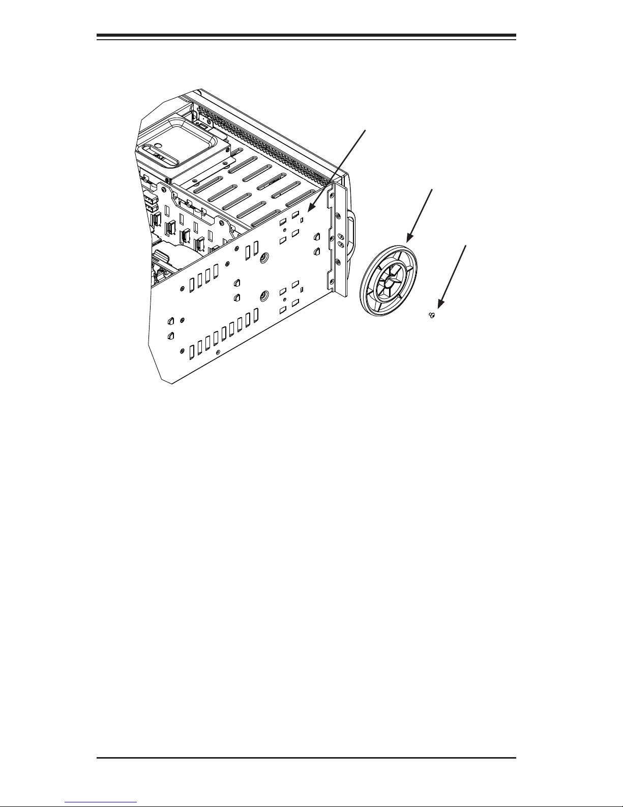
Removing the Chassis Feet
1. Place the chassis on its side with the chassis side cover facing upward.
2. Remove the screw holding the chassis foot in place.
3. The foot lock is a tab located in the center of the foot that prevents the foot
from sliding. Using a fl at head screwdriver, gently lift the foot lock upward
and slide the foot toward the rear of the chassis.
4. Repeat steps 2 and 3 with each remaining foot.
Identifying the Sections of the Rack Rails
The chassis package includes two rack rail assemblies in the rack mounting kit.
Each assembly consists of two sections: an inner fi xed chassis rail that secures
directly to the workstation chassis and an outer fi xed rack rail that secures directly
to the rack itself.
2-4
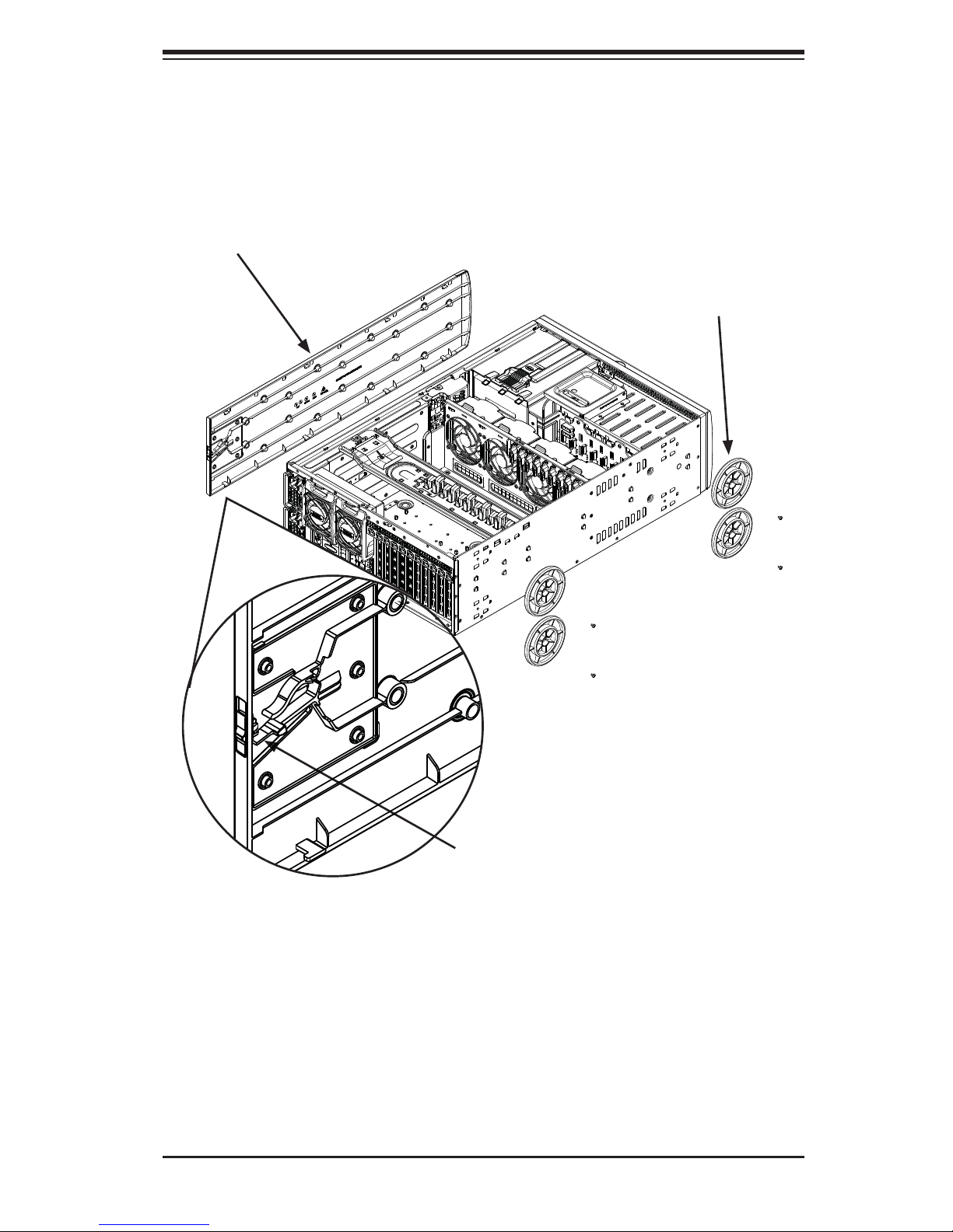
Figure 2-1. Removing the Feet and Chassis Top Cover
Chassis Cover
Chapter 2: Workstation Installation
Chassis Feet
Chassis Cover Lock
2-5
SUPERWORKSTATION 7047GR-TRF User's Manual
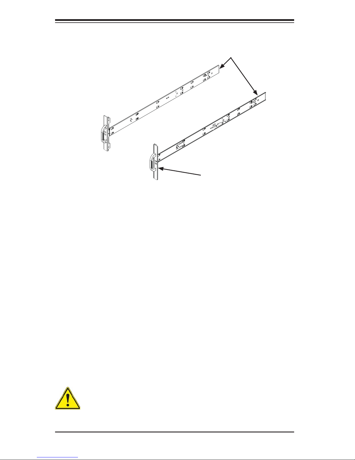
Figure 2-2. Identifying the Inner Rails and Chassis Handles
Inner Rails
Chassis Handle
Installing the Chassis Handles and Inner Rails
Installing the Inner Rails
1. Locate the chassis handles and handle screws.
2. Align the chassis handle with the front of the chassis and secure with the
three chassis handle screws.
3. Repeats steps 1 and 2 with the other handle.
4. Locate the inner rails and screws in the shipping package.
5. Align the inner rails against the chassis, as shown. Confi rm that the rails are
fl ushed against the edge of the chassis.
6. Tighten the screws. Do not over-tighten.
7. Repeat steps 5 and 6 with the other inner rail.
Warning: do not pick up the server with the front handles. They are designed to pull the system from a rack only.
2-6
Chapter 2: Workstation Installation
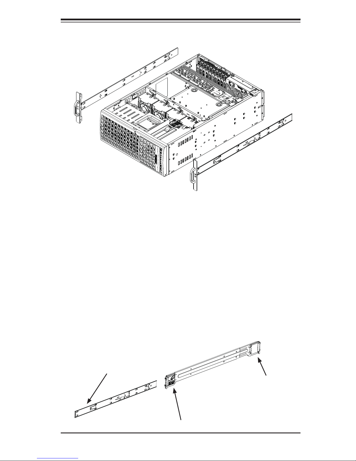
Figure 2-3. Installing the Inner Rack Rails
Installing the Outer Rails to the Rack
Installing the Outer Rails
1. Attach the rear bracket to the middle bracket.
2. Adjust both the brackets to the proper distance so that the rail fi ts snugly into
the rack.
3. Secure the rear of the outer rail with two M5 screws and the rear of the rack.
Note: The outer rail is adjustable from approximately 26" to 38.25".
4. Repeat steps 1-3 for the left outer rail.
Figure 2-4. Assembling the Outer Rails
Slide into the Inner Rail
Secure to the
Rear of the Rack
Attach to Middle Rail
2-7
SUPERWORKSTATION 7047GR-TRF User's Manual
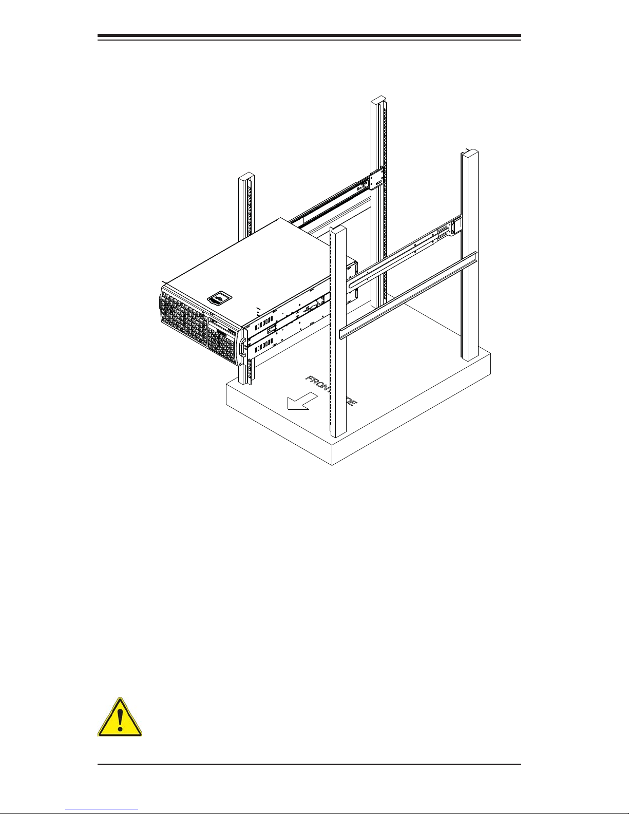
Figure 2-5. Installing the Rack Rails
Installing the Chassis into a Rack
Installing the Chassis
1. Confi rm that chassis includes the inner rails and the outer rails.
2. Align the inner chassis rails with the front of the outer rack rails (C).
3. Slide the inner rails into the outer rails, keeping the pressure even on both
sides (you may have to depress the locking tabs when inserting). When
the chassis has been pushed completely into the rack, you should hear the
locking tabs "click" into the locked position.
Stability hazard. The rack stabilizing mechanism must be in place, or the
rack must be bolted to the fl oor before you slide the unit out for servicing.
Failure to stabilize the rack can cause the rack to tip over.
2-8
Chapter 2: Workstation Installation
2-5 Tower Mounting Instructions
The SC747 chassis is shipped with the chassis cover and feet pre-installed. To use
the chassis as a desktop workstation, no other installation is required.
Use the instructions in this section if you have converted the chassis for rack use
and need to return the chassis to tower mounting.
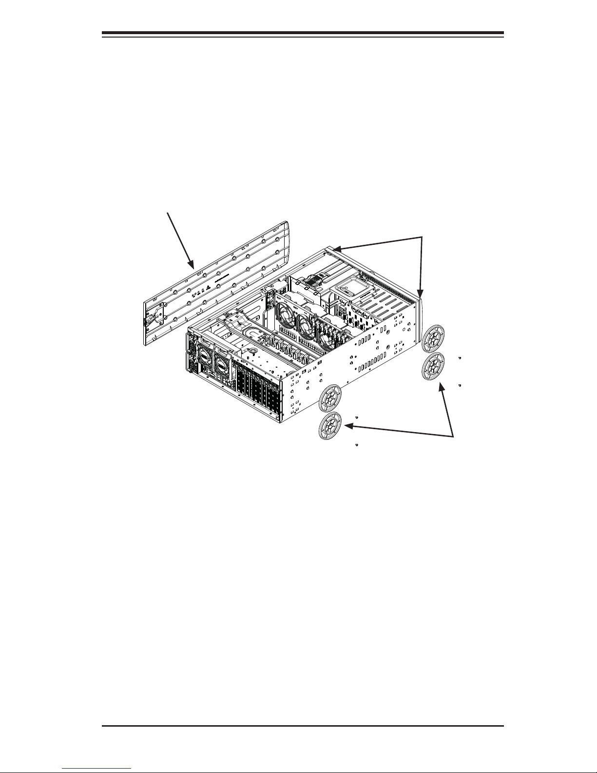
Figure 2-6. Adding Chassis Feet and Top Cover
Chassis Cover
Chassis Rackmount Ears
Chassis Feet
Installing the Chassis Cover
Installing the Cover
1. Remove the rack mount ears.
2. Align the cover post with the corresponding holes on the top of the chassis
and place the cover on top of the chassis. The cover should overhang
approximately one-half inch over the front of the chassis.
3. Slide the chassis cover toward the rear of the chassis to lock the cover into
place.
2-9
SUPERWORKSTATION 7047GR-TRF User's Manual
Figure 2-7. Placing Chassis Feet
Chassis Foot
Receptacle
Chassis Foot
Chassis Screw
Installing Feet on the Chassis
Installing the Chassis Feet
1. Place the chassis foot in the foot receptacle and slide the foot toward the
front of the chassis. The foot should lock into place.
2. Secure the foot to the chassis using one screw enclosed in the packaging.
3. Repeat steps 1 and 2 for the remaining three chassis feet.
2-10
Chapter 3: System Interface
Chapter 3
System Interface
3-1 Overview
There are several LEDs on the control panel as well as others on the drive carriers
to keep you constantly informed of the overall status of the system as well as the
activity and health of specifi c components. There are two buttons on the chassis
a control panel: a reset button and an on/off switch. This chapter explains the
meanings of all LED indicators and the appropriate response you may need to take.
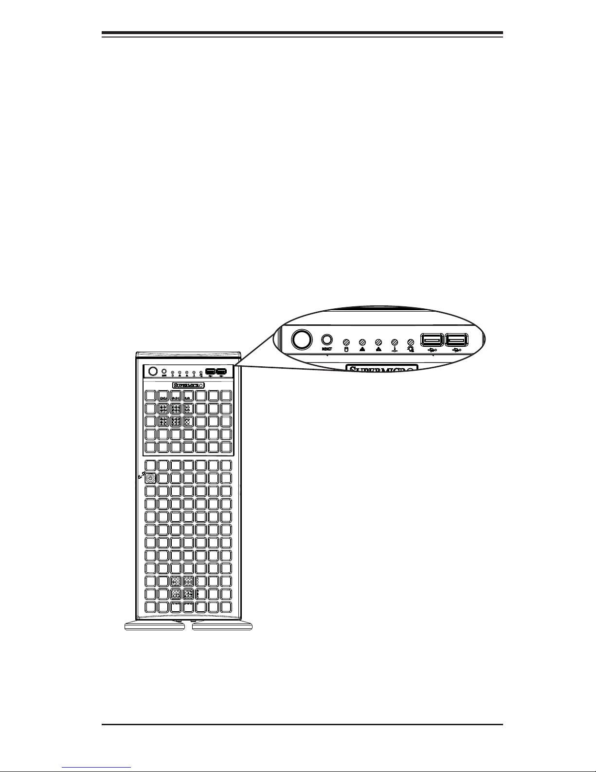
Figure 3-1. Front LEDs
3-1

SUPERWORKSTATION 7047GR-TRF User's Manual
3-2 Control Panel Buttons
There are two push-buttons located on the front of the chassis. These are power
on/off button and a reset button.
Power
The main power switch is used to apply or remove power from the power supply
to the workstation. Turning off system power with this button removes the main
power but keeps standby power supplied to the system. Therefore, you must unplug
system before servicing.
Reset
The reset button is used to reboot the system.
3-3 Control Panel LEDs
The control panel located on the front of the SC747 chassis has fi ve LEDs. These
LEDs provide you with critical information related to different parts of the system.
This section explains what each LED indicates when illuminated and any corrective
action you may need to take.
HDD
Indicates IDE channel activity. SAS/SATA and/or DVD-ROM drive activity when
fl ashing.
3-2
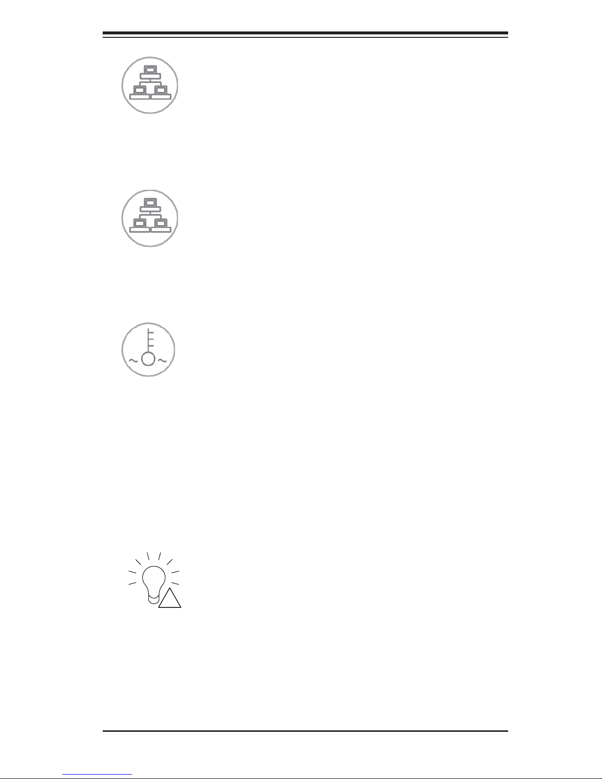
NIC1
Indicates network activity on LAN1 when fl ashing.
NIC2
Indicates network activity on LAN2 when fl ashing.
Chapter 3: System Interface
Overheat/Fan Fail
When this LED fl ashes it indicates a fan failure. When continuously on (not fl ashing)
it indicates an overheat condition, which may be caused by cables obstructing the
airfl ow in the system or the ambient room temperature being too warm. Check the
routing of the cables and make sure all fans are present and operating normally.
You should also check to make sure that the chassis covers are installed. Finally,
verify that the heatsinks are installed properly. This LED will remain fl ashing or on
as long as the overheat condition exists.
Power Fail
Indicates a power failure to the system's power supply units.
3-3

SUPERWORKSTATION 7047GR-TRF User's Manual
3-4 Drive Carrier LEDs
Each SATA drive carrier has two LEDs.
• Green: Each drive carrier has a green LED. When illuminated, this green LED
(on the front of the drive carrier) indicates drive activity. A connection to the
SATA backplane enables this LED to blink on and off when that particular drive
is being accessed.
• Red: The red LED indicates a SAS/SATA drive failure. If one of the SATA drives
fail, you should be notifi ed by your system management software.
3-4
Chapter 4: Warning Statements for AC Systems
Chapter 4
Standardized Warning Statements for AC Systems
4-1 About Standardized Warning Statements
The following statements are industry standard warnings, provided to warn the user
of situations which have the potential for bodily injury. Should you have questions
or experience difficulty, contact Supermicro's Technical Support department
for assistance. Only certifi ed technicians should attempt to install or confi gure
components.
Read this appendix in its entirety before installing or confi guring components in the
Supermicro chassis.
These warnings may also be found on our web site at http://www.supermicro.com/
about/policies/safety_information.cfm.
Warning Defi nition
Warning!
This warning symbol means danger. You are in a situation that could cause bodily
injury. Before you work on any equipment, be aware of the hazards involved with
electrical circuitry and be familiar with standard practices for preventing accidents.
警告の定義
この警告サインは危険を意味します。
人身事故につながる可能性がありますので、いずれの機器でも動作させる前に、
電気回路に含まれる危険性に注意して、標準的な事故防止策に精通して下さい。
此警告符号代表危险。
您正处于可能受到严重伤害的工作环境中。在您使用设备开始工作之前,必须充分
意识到触电的危险,并熟练掌握防止事故发生的标准工作程序。请根据每项警告结
尾的声明号码找到此设备的安全性警告说明的翻译文本。
此警告符號代表危險。
您正處於可能身體可能會受損傷的工作環境中。在您使用任何設備之前,請注意觸
電的危險,並且要熟悉預防事故發生的標準工作程序。請依照每一注意事項後的號
碼找到相關的翻譯說明內容。
4-1

SUPERWORKSTATION 7047GR-TRF User's Manual
ןונקת תורהצהאהרהז
Warnung
WICHTIGE SICHERHEITSHINWEISE
Dieses Warnsymbol bedeutet Gefahr. Sie befi nden sich in einer Situation, die zu
Verletzungen führen kann. Machen Sie sich vor der Arbeit mit Geräten mit den
Gefahren elektrischer Schaltungen und den üblichen Verfahren zur Vorbeugung
vor Unfällen vertraut. Suchen Sie mit der am Ende jeder Warnung angegebenen
Anweisungsnummer nach der jeweiligen Übersetzung in den übersetzten
Sicherheitshinweisen, die zusammen mit diesem Gerät ausgeliefert wurden.
BEWAHREN SIE DIESE HINWEISE GUT AUF.
INSTRUCCIONES IMPORTANTES DE SEGURIDAD
Este símbolo de aviso indica peligro. Existe riesgo para su integridad física. Antes
de manipular cualquier equipo, considere los riesgos de la corriente eléctrica y
familiarícese con los procedimientos estándar de prevención de accidentes. Al
fi nal de cada advertencia encontrará el número que le ayudará a encontrar el texto
traducido en el apartado de traducciones que acompaña a este dispositivo.
GUARDE ESTAS INSTRUCCIONES.
IMPORTANTES INFORMATIONS DE SÉCURITÉ
Ce symbole d'avertissement indique un danger. Vous vous trouvez dans une
situation pouvant entraîner des blessures ou des dommages corporels. Avant
de travailler sur un équipement, soyez conscient des dangers liés aux circuits
électriques et familiarisez-vous avec les procédures couramment utilisées pour
éviter les accidents. Pour prendre connaissance des traductions des avertissements
fi gurant dans les consignes de sécurité traduites qui accompagnent cet appareil,
référez-vous au numéro de l'instruction situé à la fi n de chaque avertissement.
CONSERVEZ CES INFORMATIONS.
ןה תואבה תורהצהא ינפמ שמתשמה תא ריהזהל תנמ לע ,היישעתה ינקת יפ לע תורהז הלבח
ה וא תולאש שיו הדימב .תירשפא תיזיפי ,יהשלכ היעבב תולקתרוציל שי הכימת תקלחמ םע רשק
רידגהל וא ןיקתהל םיאשר דבלב םיכמסומ םיאנכט .ורקימרפוס לש תינכט תאה .םיביכר
תרדגה וא תנקתה ינפל ואולמב חפסנה תא
אורקל שי .ורקימרפוס יזראמב םיביכרה
4-2
 Loading...