

Page 1
SUPER
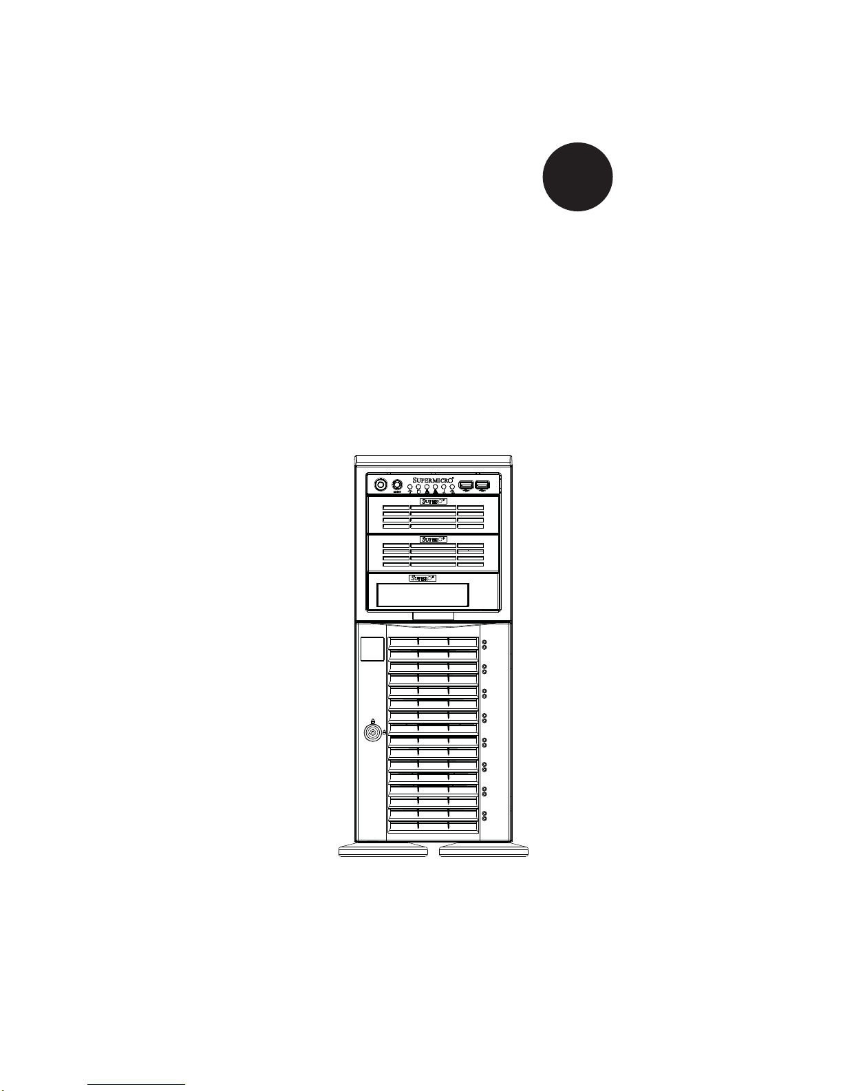
SuperWorkstation 7046A-6
®
USER’S MANUAL
1.0
Page 2

The information in this User’s Manual has been carefully reviewed and is believed to be accurate.
The vendor assumes no responsibility for any inaccuracies that may be contained in this document,
makes no commitment to update or to keep current the information in this manual, or to notify any
person or organization of the updates. Please Note: For the most up-to-date version of this
manual, please see our web site at www.supermicro.com.
Super Micro Computer, Inc. ("Supermicro") reserves the right to make changes to the product
described in this manual at any time and without notice. This product, including software, if any,
and documentation may not, in whole or in part, be copied, photocopied, reproduced, translated or
reduced to any medium or machine without prior written consent.
IN NO EVENT WILL SUPERMICRO BE LIABLE FOR DIRECT, INDIRECT, SPECIAL, INCIDENTAL,
SPECULATIVE OR CONSEQUENTIAL DAMAGES ARISING FROM THE USE OR INABILITY TO
USE THIS PRODUCT OR DOCUMENTATION, EVEN IF ADVISED OF THE POSSIBILITY OF
SUCH DAMAGES. IN PARTICULAR, SUPERMICRO SHALL NOT HAVE LIABILITY FOR ANY
HARDWARE, SOFTW ARE, OR DA TA STORED OR USED WITH THE PRODUCT, INCLUDING THE
COSTS OF REPAIRING, REPLACING, INTEGRATING, INSTALLING OR RECOVERING SUCH
HARDWARE, SOFTWARE, OR DATA.
Any disputes arising between manufacturer and customer shall be governed by the laws of Santa
Clara County in the State of California, USA. The State of California, County of Santa Clara shall
be the exclusive venue for the resolution of any such disputes. Super Micro's total liability for
all claims will not exceed the price paid for the hardware product.
This equipment has been tested and found to comply with the limits for a Class B digital device
pursuant to Part 15 of the FCC Rules. These limits are designed to provide reasonable protection
against harmful interference in a residential installation. This equipment generates, uses, and can
radiate radio frequency energy and, if not installed and used in accordance with the manufacturer’s
instruction manual, may cause interference with radio communications. However, there is no
guarantee that interference will not occur in a particular installation. If this equipment does cause
harmful interference to radio or television reception, which can be determined by turning the
equipment off and on, you are encouraged to try to correct the interference by one or more of the
following measures: Reorient or relocate the receiving antenna. Increase the separation between
the equipment and the receiver. Connect the equipment into an outlet on a circuit different from
that to which the receiver is connected. Consult the dealer or an experienced radio/television
technician for help.
California Best Management Practices Regulations for Perchlorate Materials: This Perchlorate
warning applies only to products containing CR (Manganese Dioxide) Lithium coin cells. “Perchlorate
Material-special handling may apply. See www.dtsc.ca.gov/hazardouswaste/perchlorate”
WARNING: Handling of lead solder materials used in this
product may expose you to lead, a chemical known to
the State of California to cause birth defects and other
reproductive harm.
Manual Revision 1.0
Release Date: November 16, 2009
Unless you request and receive written permission from Super Micro Computer, Inc., you may
not copy any part of this document.
Information in this document is subject to change without notice. Other products and companies
referred to herein are trademarks or registered trademarks of their respective companies or mark
holders.
Copyright © 2009 by Super Micro Computer, Inc.
All rights reserved.
Printed in the United States of America
Page 3

Preface
About This Manual
This manual is written for professional system integrators and PC technicians. It
provides information for the installation and use of the SuperWorkstation 7046A-
6. Installation and maintenance should be performed by experienced technicians
only.
The SuperWorkstation 7046A-6 is a high-end system based on the SC743TS865BP-SQ tower/4U rackmount chassis and the X8DA6 serverboard.
Preface
Manual Organization
Chapter 1: Introduction
The fi rst chapter provides a checklist of the main components included with the sys-
tem and describes the main features of the X8DA6 serverboard and the SC743TS865BP-SQ chassis, which comprise the SuperWorkstation 7046A-6.
Chapter 2: Server Installation
This chapter describes the steps necessary to setup the SuperWorkstation 7046A-6
into a rack and check out the server confi guration prior to powering up the system. If
your system was ordered without processor and memory components, this chapter
will refer you to the appropriate sections of the manual for their installation.
Chapter 3: System Interface
Refer here for details on the system interface, which includes the functions and
information provided by the control panel on the chassis as well as other LEDs
located throughout the system.
Chapter 4: System Safety
You should thoroughly familiarize yourself with this chapter for a general overview
of safety precautions that should be followed when installing and servicing the
SuperWorkstation 7046A-6.
iii
Page 4

SuperWorkstation 7046A-6 User's Manual
Chapter 5: Advanced Serverboard Setup
Chapter 5 provides detailed information on the X8DA6 serverboard, including the
locations and functions of connections, headers and jumpers. Refer to this chapter
when adding or removing processors or main memory and when reconfi guring the
serverboard.
Chapter 6: Advanced Chassis Setup
Refer to Chapter 6 for detailed information on the SC743TS-865BP-SQ chassis.
You should follow the procedures given in this chapter when installing, removing
or reconfi guring SAS/SATA or peripheral drives and when replacing system power
supply units and cooling fans.
Chapter 7: BIOS
The BIOS chapter includes an introduction to BIOS and provides detailed information on running the CMOS Setup Utility.
Appendix A: POST Error Beep Codes
Appendix B: System Specifi cations
iv
Page 5

Notes
Preface
v
Page 6

SuperWorkstation 7046A-6 User's Manual
Table of Contents
Chapter 1 Introduction
1-1 Overview .........................................................................................................1-1
1-2 Serverboard Features .....................................................................................1-2
Processors ......................................................................................................1-2
Memory ...........................................................................................................1-2
Serial ATA ....................................................................................................... 1-2
SAS ................................................................................................................ 1-2
PCI Expansion Slots ....................................................................................... 1-2
Onboard Controllers/Ports .............................................................................. 1-3
Other Features ................................................................................................ 1-3
1-3 Chassis Features ............................................................................................1-3
System Power ................................................................................................. 1-3
SAS Subsystem .............................................................................................. 1-3
Front Control Panel .........................................................................................1-3
I/O Backplane .................................................................................................. 1-3
Cooling System ............................................................................................... 1-4
1-4 Contacting Supermicro ....................................................................................1-6
Chapter 2 Installation
2-1 Overview .........................................................................................................2-1
2-2 Unpacking the System .................................................................................... 2-1
2-3 Preparing for Setup .........................................................................................2-1
Choosing a Setup Location ............................................................................. 2-2
Rack Precautions ............................................................................................ 2-2
Server Precautions .......................................................................................... 2-2
Rack Mounting Considerations ....................................................................... 2-3
Ambient Operating Temperature ................................................................ 2-3
Reduced Airfl ow .........................................................................................2-3
Mechanical Loading ................................................................................... 2-3
Circuit Overloading .....................................................................................2-3
Reliable Ground ......................................................................................... 2-3
2-4 Installing the System into a Rack ................................................................... 2-4
Identifying the Sections of the Rack Rails ......................................................2-4
Installing the Chassis Rails .............................................................................2-5
Installing the Rack Rails .................................................................................2-6
vi
Page 7

Table of Contents
Installing the System into the Rack ................................................................ 2-7
2-5 Checking the Serverboard Setup .................................................................... 2-8
2-6 Checking the Drive Bay Setup ........................................................................ 2-9
Chapter 3 System Interface
3-1 Overview .........................................................................................................3-1
3-2 Control Panel Buttons ..................................................................................... 3-1
Power ..............................................................................................................3-1
Reset ...............................................................................................................3-1
3-3 Control Panel LEDs ........................................................................................3-2
Power ..............................................................................................................3-2
HDD .................................................................................................................3-2
NIC1 ................................................................................................................3-2
NIC2 ................................................................................................................3-2
Overheat/Fan Fail ........................................................................................... 3-2
Power Fail .......................................................................................................3-3
3-4 Drive Carrier LEDs ..........................................................................................3-3
SAS Drives ......................................................................................................3-3
SATA Drives ....................................................................................................3-3
Chapter 4 System Safety
4-1 Electrical Safety Precautions .......................................................................... 4-1
4-2 General Safety Precautions ............................................................................ 4-2
4-3 ESD Precautions ............................................................................................. 4-3
4-4 Operating Precautions .................................................................................... 4-4
Chapter 5 Advanced Serverboard Setup
5-1 Handling the Serverboard ............................................................................... 5-1
Precautions .....................................................................................................5-1
Unpacking .......................................................................................................5-2
5-2 Serverboard Installation ..................................................................................5-2
5-3 Connecting Cables .......................................................................................... 5-3
Connecting Data Cables ................................................................................. 5-3
Connecting Power Cables .............................................................................. 5-3
Connecting the Control Panel .........................................................................5-3
5-4 I/O Ports .......................................................................................................... 5-4
5-5 Processor and Heatsink Installation................................................................5-5
Installing an LGA 1366 Processor.............................................................. 5-5
5-6 Installing Memory Modules ............................................................................. 5-8
Installing & Removing DIMMs ......................................................................... 5-8
Memory Support .............................................................................................. 5-9
vii
Page 8

SuperWorkstation 7046A-6 User's Manual
5-7 Adding PCI Add-On Cards ............................................................................ 5-10
5-8 Serverboard Details .......................................................................................5-11
X8DA6 Quick Reference ...............................................................................5-12
5-9 Connector Defi nitions ...................................................................................5-13
5-10 Jumper Settings ............................................................................................5-19
5-11 Onboard Indicators ........................................................................................5-22
5-12 Floppy, SAS and SATA Ports ........................................................................ 5-23
5-13 Installing Additional Drivers ...........................................................................5-24
5-14 Supero Doctor III ...........................................................................................5-25
Chapter 6 Advanced Chassis Setup
6-1 Static-Sensitive Devices ..................................................................................6-1
Precautions .....................................................................................................6-1
Unpacking .......................................................................................................6-1
6-2 Front Control Panel .........................................................................................6-3
6-3 System Fans ...................................................................................................6-4
Fan Failure ...................................................................................................... 6-4
Replacing Chassis Cooling Fans ....................................................................6-4
6-4 Drive Bay Installation ......................................................................................6-6
SAS/SATA Backplane ......................................................................................6-7
Installing Components in the 5.25" Drive Bays .............................................. 6-8
6-5 Power Supply ..................................................................................................6-9
Power Supply Failure ......................................................................................6-9
Chapter 7 BIOS
7-1 Introduction ......................................................................................................7-1
Starting BIOS Setup Utility .............................................................................. 7-1
How To Change the Confi guration Data ......................................................... 7-1
Starting the Setup Utility ................................................................................. 7-2
7-2 Main Setup ......................................................................................................7-2
7-3 Advanced Setup Confi gurations......................................................................7-4
7-4 Security Settings ........................................................................................... 7-20
7-5 Boot Confi guration ........................................................................................7-22
7-6 Exit Options ................................................................................................... 7-23
Appendix A BIOS Error Beep Codes
Appendix B System Specifi cations
viii
Page 9

Chapter 1: Introduction
Chapter 1
Introduction
1-1 Overview
The 7046A-6 is a high-end workstation comprised of two main subsystems: the
SC743TS-865BP-SQ tower/4U chassis and the X8DA6 dual Intel® Xeon® processor serverboard. Please refer to our web site for information on operating systems
that have been certifi ed for use with the SuperWorkstation 7046A-6 (www.super-
micro.com).
In addition to the serverboard and chassis, various hardware components have
been included with the SuperWorkstation 7046A-6, as listed below:
Two 8-cm hot-swap PWM "SuperQuiet" chassis fans (FAN-0104L4)
•
One 9-cm PWM "SuperQuiet" exhaust fan (FAN-0103L4)•
Two active CPU heatsinks (SNK-P0040AP4)•
SAS Accessories •
One SATA backplane (CSE-SAS-743TQ)
Six SATA cables (CBL-0061L)
Two SGPIO cables (CBL-0157L)
One internal to external IEEE1394 "FireWire" cable (CBL-0173L)
Eight hot-swap drive carriers (CSE-PT17L-BOEM)
Optional:
•
Two 8-cm PWM fans (FAN-0104L4)
One rackmount kit [CSE-PT26L-(B)]
1-1
Page 10

SuperWorkstation 7046A-6 User's Manual
1-2 Serverboard Features
At the heart of the SuperWorkstation 7046A-6 lies the X8DA6, a dual processor
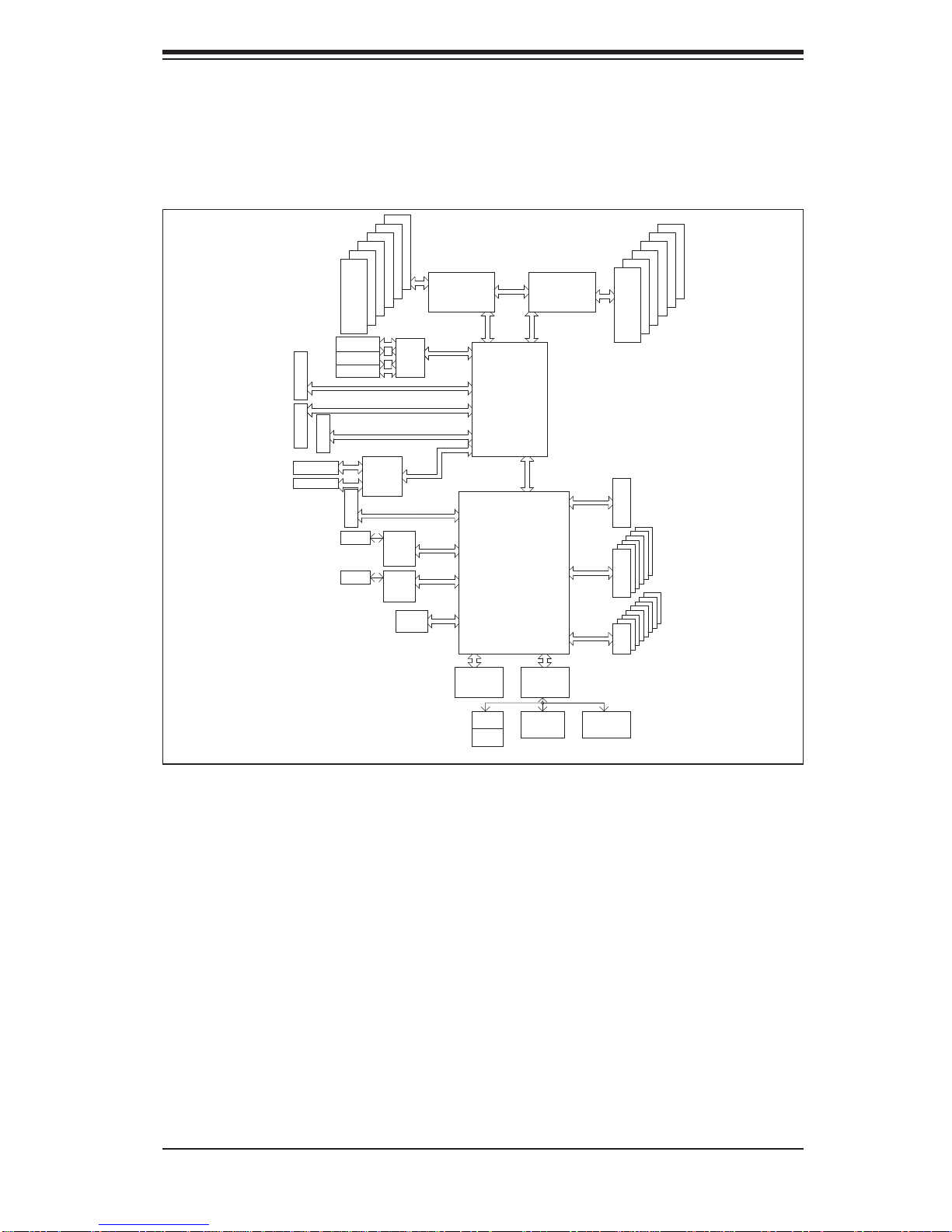
serverboard based on the Intel 5520 + ICH10R chipset. Below are the main features
of the X8DA6. (See Figure 1-1 for a block diagram of the chipset).
Processors
The X8DA6 supports two Intel 5500 series (LGA 1366) processors. Please refer to
the serverboard description pages on our web site for a complete listing of supported
processors (www.supermicro.com).
Memory
The X8DA6 has twelve DIMM slots that can support up to 96 GB or registered ECC
or up to 24 GB of unbuffered ECC or non-ECC DDR3-1333/1066/800 SDRAM.
Modules of the same size and speed should be used. See Chapter 5 for details.
Serial ATA
A SATA controller is integrated into the South Bridge (ICH10R) section of the chipset
to provide a six-port Serial ATA subsystem, which is RAID 0, 1, 10 and 5 capable.
The Serial ATA drives are hot-swappable units.
Note: The operati ng system yo u use must h ave R AID su ppor t to e nable t he hotswap capability and RAI D function of the Serial ATA drives.
SAS
An LSI 2008 SAS controller is integrated into the serverboard to support eight SAS2
ports, which are RAID 0, 1 and 10 capable. The SAS drives are hot-swappable
units. SAS RAID 5 is also supported with the AOC-IMRRAkey-LSI-2008 (optional)
installed on the serverboard.
Note: The operati ng system yo u use must h ave R AID su ppor t to e nable t he hotswap capability and RAI D function of the SAS drives.
PCI Expansion Slots
The X8DA6 has one PCI-E x16 slot, two PCI-E 2.0 x4 (in x8) slots, one PCI-E x4
(in x8) slot, two 64-bit PCI-X 133/100 slots and one 64-bit PCI-X 133 slot.
1-2
Page 11

Chapter 1: Introduction
Onboard Controllers/Ports
A fl oppy drive controller is provided on the serverboard. The color-coded I/O ports
include two COM ports, four USB 2.0 ports, PS/2 mouse and keyboard ports, two
Gb Ethernet ports and six HDA (High Defi nition Audio) ports.
Other Features
Other onboard features that promote system health include onboard voltage monitors, auto-switching voltage regulators, chassis and CPU overheat sensors, virus
protection and BIOS rescue.
1-3 Chassis Features
The SuperWorkstation 7046A-6 is a scaleable system designed with today's most
state-of-the-art features. The following is a general outline of the main features of
the SC743TS-865BP-SQ chassis.
System Power
The 7046A-6 features a single 865W power supply . This power supply unit has been
designed to operate at a low noise level to make it ideal for use in a workstation
environment.
SAS Subsystem
The SC743TS-865BP-SQ chassis was designed to support eight SAS hard drives,
which a re hot- swappa ble unit s.
Front Control Panel
The control panel on the SuperWorkstation 7046A-6 provides you with system
monitoring and control. LEDs indicate system power, HDD activity, network activity,
overheat conditions and power supply failure. A main power button and a system
reset button are also included.
Note: the power supply fail LED indicates the power supply fan has failed.
I/O Backplane
The SC743TS-865BP-SQ is an ATX form factor chassis that can be used as a tower
or mounted in a 4U rackmount confi guration. The I/O backplane provides seven
expansion slots, two COM ports, a parallel port, four USB 2.0 ports, PS/2 mouse
and keyboard ports, two Gigabit Ethernet port(s) and 7.1 HDA ports.
1-3
Page 12

SuperWorkstation 7046A-6 User's Manual
Cooling System
The SC743TS-865BP-SQ chassis has an innovative "Super Quiet" cooling design
that provides suffi cient cooling at very low noise level - ideal for a workplace envi-
ronment. The chassis includes two 8-cm hot-plug PWM (Pulse Width Modulation)
system cooling fans located in the middle of the chassis. The system cooling fans
fans work with an air shroud to cool the areas where the most heat is generated. A
9-cm PWM exhaust fan is also located at the rear of the chassis.
The power supply has two fans for redundancy; if one fan fails the other will incease
its rpm to compensate. This may cause the system to run louder than usual. See
details in Chapter 6.
1-4
Page 13
Chapter 1: Introduction
Figure 1-1. Intel 5520 Chipset:
System Block Diagram
Note: This is a general block diagram. Please see Chapter 5 for details.
#1-6
Slot 1
Slot 2
Slot 3
Slot 6
PCI-E x16
Slot 7
PCI-E x8
Slot 5
Ports 0~3
Ports 4~7
#1-3
#1-2
#1-1
DDR3
800/1066/1333
PCI-X 133/100
PCI-X 133/100
PCI-X 133
PCI-E x8
LSI SA2008
Slot 4
PCI-E x8
PHY#1
PHY#1
#1-5
#1-4
SAS2
Option
PXH
PCI-E x4
LAN#1
82574L
LAN#2
82574L
1394
PCI-E x8
PCI-E x16
PCI-E x4
PCI-E x4
PCI-E x4
PCI-E x1
PCI-E x1
PCI
CPU#2
PCI-E x9
QPI
Ports 7,8
Intel 5520
IOH-36D
Ports 3-6
Ports 1,2
Port 10
Port 9
Lane 1/2/3/4
Intel ICH10R
Lane 5
Lane 6
SPI
QPI
Port 0
ESI
DMI
CPU#1
QPI
PCIE x4
SIO
W83627
HG
AC Link
3.0 Gb/S
USB 2.0
2 Rear
4 Front
1 Type-A
#0-3
#0-2
#0-1
DDR3
800/1066/1333
HD AUDIO
0~5
SATA
0~8
USB
#0-4
#0-5
#0-6
Mouse
Kybrd
COM1
(External)
COM2
(External)
1-5
Page 14

SuperWorkstation 7046A-6 User's Manual
1-4 Contacting Supermicro
Headquarters
Address: Super Micro Computer, Inc.
980 Rock Ave.
San Jose, CA 95131 U.S.A.
[email protected] (Technical Support)
Web Site: www.supermicro.com
Europe
Address: Super Micro Computer B.V.
Het Sterrenbeeld 28, 5215 ML
's-Hertogenbosch, The Netherlands
[email protected] (Technical Support)
[email protected] (Customer Support)
Asia-Pacifi c
Address: Super Micro Computer, Inc.
4F, No. 232-1, Liancheng Rd.
Chung-Ho 235, Taipei County
Taiwan, R.O.C.
Tel: +886-(2) 8226-3990
Fax: +886-(2) 8226-3991
Web Site: www.supermicro.com.tw
Technical Support:
Email: [email protected]
Tel: 886-2-8228-1366, ext.132 or 139
1-6
Page 15

Chapter 2: Installation
Chapter 2
Installation
2-1 Overview
This chapter provides a quick setup checklist to get your SuperWorkstation 7046A-6
up and running. Following these steps in the order given should enable you to have
the system operational within a minimum amount of time. This quick setup assumes
that your system has come to you with the processor and memory preinstalled. If
your system is not already fully integrated with a serverboard, processor, system
memory etc., please turn to the chapter or section noted in each step for details on
installing specifi c components.
The 7046A-6 may be employed either as a tower or mounted in a rack as a 4U
rackmount chassis. If using it as a tower unit, please read the Server Precautions
in the next section and then skip ahead to Section 2-5.
2-2 Unpacking the System
You should inspect the box the system was shipped in and note if it was damaged
in any way. If the system itself shows damage you should fi le a damage claim with
the carrier who delivered it.
Decide on a suitable location for the SuperWorkstation 7046A-6. It should be
situated in a clean, dust-free area that is well ventilated. Avoid areas where heat,
electrical noise and electromagnetic fi elds are generated. Y ou will also need it placed
near a grounded power outlet. Be sure to read the Rack and Server Precautions
in the next section.
2-3 Preparing for Setup
The box the system was shipped in may include two sets of rail assemblies, two
rail mounting brackets and mounting screws needed for installing the system into
a rack (optional kit). Follow the steps in the order given to complete the installation
process in a minimum amount of time. Please read this section in its entirety before
you begin the installation procedure outlined in the sections that follow.
2-1
Page 16
SuperWorkstation 7046A-6 User's Manual
!
!
Choosing a Setup Location
Leave enough clearance in front of the rack to enable you to open the front door •
completely (~25 inches) and approximately 30 inches of clearance in the back
of the rack to allow for suffi cient airfl ow and ease in servicing.
•
This product is for installation only in a Restricted Access Location (dedicated
equipment rooms, service closets and the like).
This product is not suitable for use with visual display work place devices
•
acccording to §2 of the the German Ordinance for Work with Visual Display
Units.
Warnings and Precautions!
Rack Precautions
Ensure that the leveling jacks on the bottom of the rack are fully extended to •
the fl oor with the full weight of the rack resting on them.
In single rack installation, stabilizers should be attached to the rack. In multiple
•
rack installations, the racks should be coupled together.
Always make sure the rack is stable before extending a component from the
•
rack.
You should extend only one component at a time - extending two or more si-
•
multaneously may cause the rack to become unstable.
Server Precautions
Review the electrical and general safety precautions in Chapter 4.•
Determine the placement of each component in the rack • before you install the
rails.
Install the heaviest server components on the bottom of the rack fi rst, and then
•
work up.
Use a regulating uninterruptible power supply (UPS) to protect the server from
•
power surges, voltage spikes and to keep your system operating in case of a
power failure.
2-2
Page 17

Chapter 2: Installation
Allow the hot plug SAS/SATA drives and power supply modules to cool before •
touching them.
Always keep the rack's front door and all panels and components on the servers
•
closed when not servicing to maintain proper cooling.
Rack Mounting Considerations
Ambient Operating Temperature
If installed in a closed or multi-unit rack assembly, the ambient operating temperature of the rack environment may be greater than the ambient temperature of the
room. Therefore, consideration should be given to installing the equipment in an
environment compatible with the manufacturer’s maximum rated ambient temperature (Tmra).
Reduced Airfl ow
Equipment should be mounted into a rack so that the amount of airfl ow required
for safe operation is not compromised.
Mechanical Loading
Equipment should be mounted into a rack so that a hazardous condition does not
arise due to uneven mechanical loading.
Circuit Overloading
Consideration should be given to the connection of the equipment to the power
supply circuitry and the effect that any possible overloading of circuits might have
on overcurrent protection and power supply wiring. Appropriate consideration of
equipment nameplate ratings should be used when addressing this concern.
Reliable Ground
A reliable ground must be maintained at all times. To ensure this, the rack itself
should be grounded. Particular attention should be given to power supply connections other than the direct connections to the branch circuit (i.e. the use of power
strips, etc.).
2-3
Page 18
SuperWorkstation 7046A-6 User's Manual
Inner rail
Outer rail
Rail brackets
2-4 Installing the System into a Rack
This section provides information on installing the system into a rack unit. Rack
installation requires the use of the optional rackmount kit. If the system has already
been mounted into a rack or if you are using it as a tower, you can skip ahead to
Sections 2-5 and 2-6.
There are a variety of rack units on the market, which may mean the assembly
procedure will differ slightly. The following is a guideline for installing the system
into a rack with the rack rails provided in the rackmount kit. You should also refer
to the installation instructions that came with the rack unit you are using.
Identifying the Sections of the Rack Rails
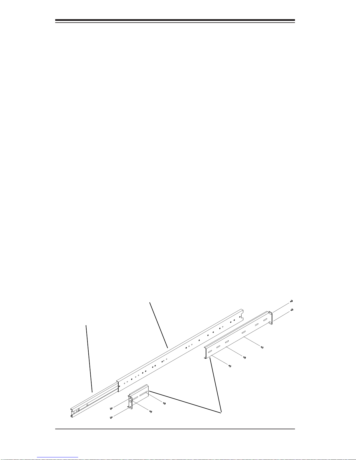
The optional rackmount kit includes two rack rail assemblies. Each of these assemblies consist of three sections: an inner fi xed chassis rail that secures to the
chassis, an outer rack rail that secures directly to the rack itself and two rail brackets,
which also attack to the rack (see Figure 2-1.) The inner and outer rails must be
detached from each other to install.
To remove the inner chassis rail, pull it out as far as possible - you should hear a
"click" sound as a locking tab emerges from inside the rail assembly and locks the
inner rail. Depress the locking tab to pull the inner rail completely out. Do this for
both assemblies (one for each side).
Figure 2-1. Identifying the Sections of the Rack Rails
2-4
Page 19

Chapter 2: Installation
Installing the Chassis Rails
You will need to remove the top cover and the feet to add rack rails to the chassis.
First, remove the top and right covers (top and left covers when standing as a tower
chassis) by fi rst removing the screws that secure them to the chassis. Depress the
button on the top (side if tower) of the chassis to release the cover and then pull
the cover off. Then unscrew the four feet and remove them from the chassis (see
Figure 2-2).
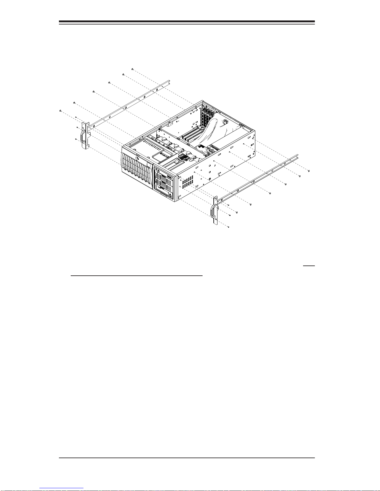
You can now attach rack rails to the top and bottom (now the sides) of the chassis.
First add the rack handles. Then position the inner chassis rail sections you just
removed along the side of the chassis making sure the screw holes line up. Note
that these two rails are left/right specifi c. Screw the rail securely to the side of the
chassis (see Figure 2-3). Repeat this procedure for the other rail on the other side
of the chassis. You will also need to attach the rail brackets when installing into a
telco rack.
Locking Tabs: As mentioned, the chassis rails have a locking tab, which serves
two functions. The fi rst is to lock the system into place when installed and pushed
fully into the rack, which is its normal position. Secondly, these tabs also lock the
system in place when fully extended from the rack. This prevents the system from
coming completely out of the rack when you pull it out for servicing.
Figure 2-2. Preparing to Install the Chassis Rails
2-5
Page 20
SuperWorkstation 7046A-6 User's Manual
Figure 2-3. Installing the Rails to the Chassis
Installing the Rack Rails
Determine where you want to place the SuperWorkstation 7046A-6 in the rack. (See
Rack and Server Precautions in Section 2-3.) Position the fi xed rack rail/sliding rail
guide assemblies at the desired location in the rack, keeping the sliding rail guide
facing the inside of the rack. Screw the assembly securely to the rack using the
brackets provided. Attach the other assembly to the other side of the rack, making
sure both are at the exact same height and with the rail guides facing inward.
2-6
Page 21
Chapter 2: Installation
Installing the System into the Rack
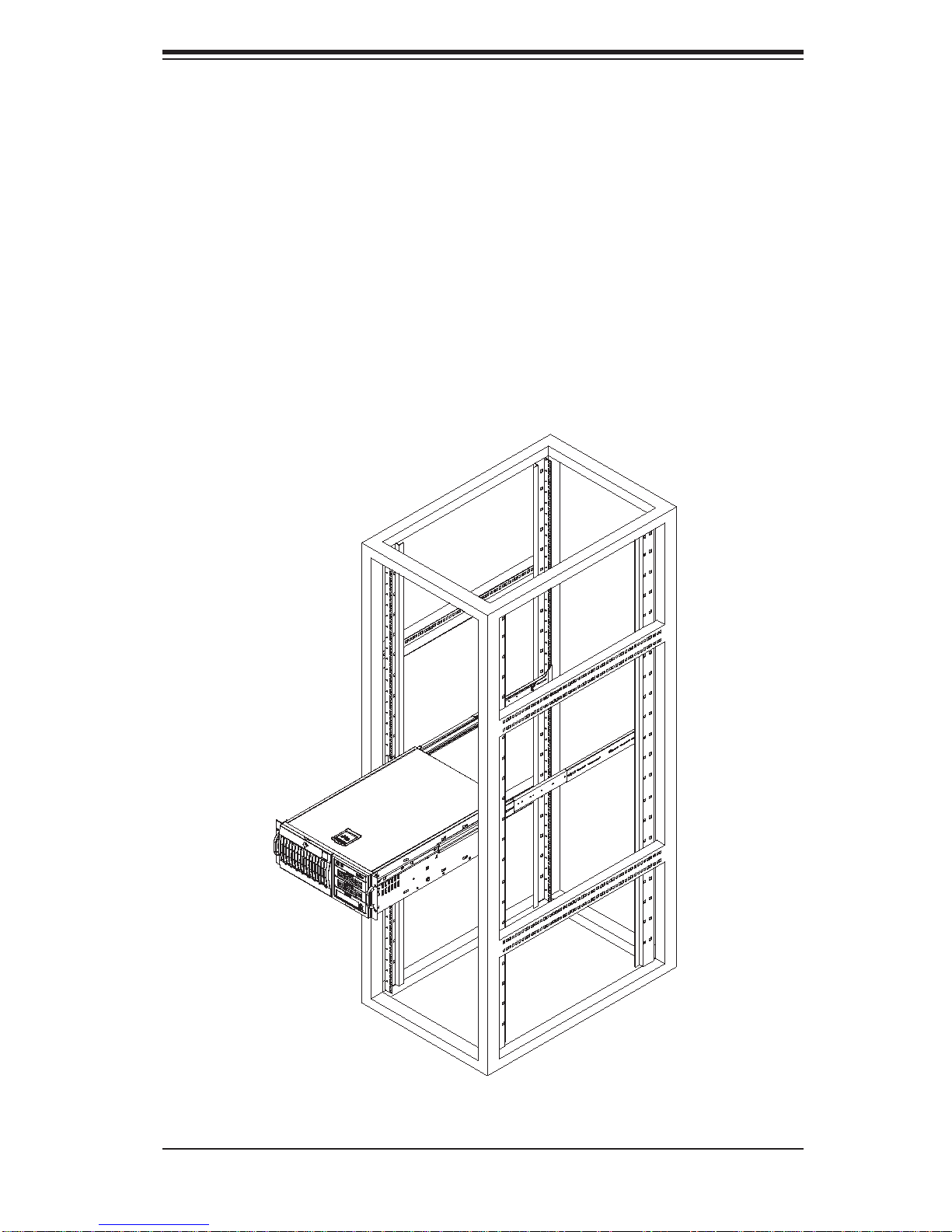
You should now have rails attached to both the chassis and the rack unit. The next
step is to install the system into the rack. You should have two brackets in the rack
mount kit. Install these fi rst keeping in mind that they are left/right specifi c (marked
with "L" and "R"). Then, line up the rear of the chassis rails with the front of the rack
rails. Slide the chassis rails into the rack rails, keeping the pressure even on both
sides (you may have to depress the locking tabs when inserting).
When the system has been pushed completely into the rack, you should hear the
locking tabs "click". Finish by inserting and tightening the thumbscrews that hold
the front of the chassis to the rack (see Figure 2-4).
Figure 2-4. Installing the System into a Rack
2-7
Page 22

SuperWorkstation 7046A-6 User's Manual
2-5 Checking the Serverboard Setup
After setting up the the system, you will need to open the unit to make sure the
serverboard is properly installed and all the connections have been made.
Accessing the Inside of the System
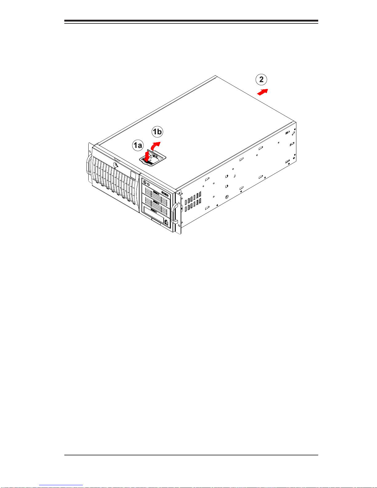
If rack mounted, grasp the two handles on either side and pull the unit 1.
straight out until it locks (you will hear a "click").
There are two screws that secure the cover to the chassis - remove these 2.
fi rst. Locate the latch on the top (side if tower) of the chassis - depress where
it says "push" then lift the latch to release the cover. You can then lift the
cover from the chassis to gain full access to the inside of the system. See
Figure 2-5.
Checking the Components and Setup
You may have a processor already installed into the serverboard. The proces-1.
sor should have its own heatsink attached. See Chapter 5 for instructions on
processor installation.
Your system may have come with system memory already installed. Make 2.
sure all DIMMs are fully seated in their slots. For details on adding system
memory, refer to Chapter 5.
If desired, you can install add-on cards to the system. See Chapter 5 for 3.
details on installing PCI add-on cards.
Make sure all power and data cables are properly connected and not blocking 4.
the chassis airfl ow. See Chapter 5 for details on cable connections.
2-8
Page 23
Chapter 2: Installation
Figure 2-5. Accessing the Inside of the System
(Rack Confi guration shown)
2-6 Checking the Drive Bay Setup
Next, you should check to make sure the peripheral drives and the SAS/SATA
drives and backplane have been properly installed and all connections have been
made.
Checking the Drives
All drives can be accessed from the front of the system. For servicing the CD-1.
ROM and fl oppy drives, you will need to remove the top/left chassis cover.
The SAS/SATA disk drives can be installed and removed from the front of the
chassis without removing any chassis covers.
To install components into the 5.25" drive bays, you must fi rst remove the 2.
top/left chassis cover as described in the previous section. Refer to Chapter 6
for details.
Refer to Chapter 6 if you need to reinstall a CD-ROM and/or fl oppy disk drive 3.
to the system.
2-9
Page 24

SuperWorkstation 7046A-6 User's Manual
Depending upon your system's confi guration, your system may have one or 4.
more drives already installed. If you need to install SAS/SATA drives, please
refer to Chapter 6.
Checking the Airfl ow
Airfl ow is provided by four hot-swap 8-cm chassis fans working in conjunction 1.
with an air shroud. One 9-cm exhaust fan is also mounted at the rear of the
chassis. The system component layout was carefully designed to promote
suffi cient airfl ow through the chassis.
Note that all power and data cables have been routed in such a way that they 2.
do not block the airfl ow generated by the fans. Keep this in mind when you
reroute them after working on the system.
Providing Power
Plug the power cords from the power supplies unit into a high-quality power 1.
strip that offers protection from electrical noise and power surges. It is recommended that you use an uninterruptible power supply (UPS).
Depress the power on button on the front of the chassis.2.
2-10
Page 25
Chapter 3: System Interface
Chapter 3
System Interface
3-1 Overview
The control panel on the 7046A-6 has several LEDs and two buttons. There are
also two LEDs on each SAS/SATA drive carrier. These LEDs keep you constantly
informed of the overall status of the system and the activity and health of specifi c
components.
3-2 Control Panel Buttons
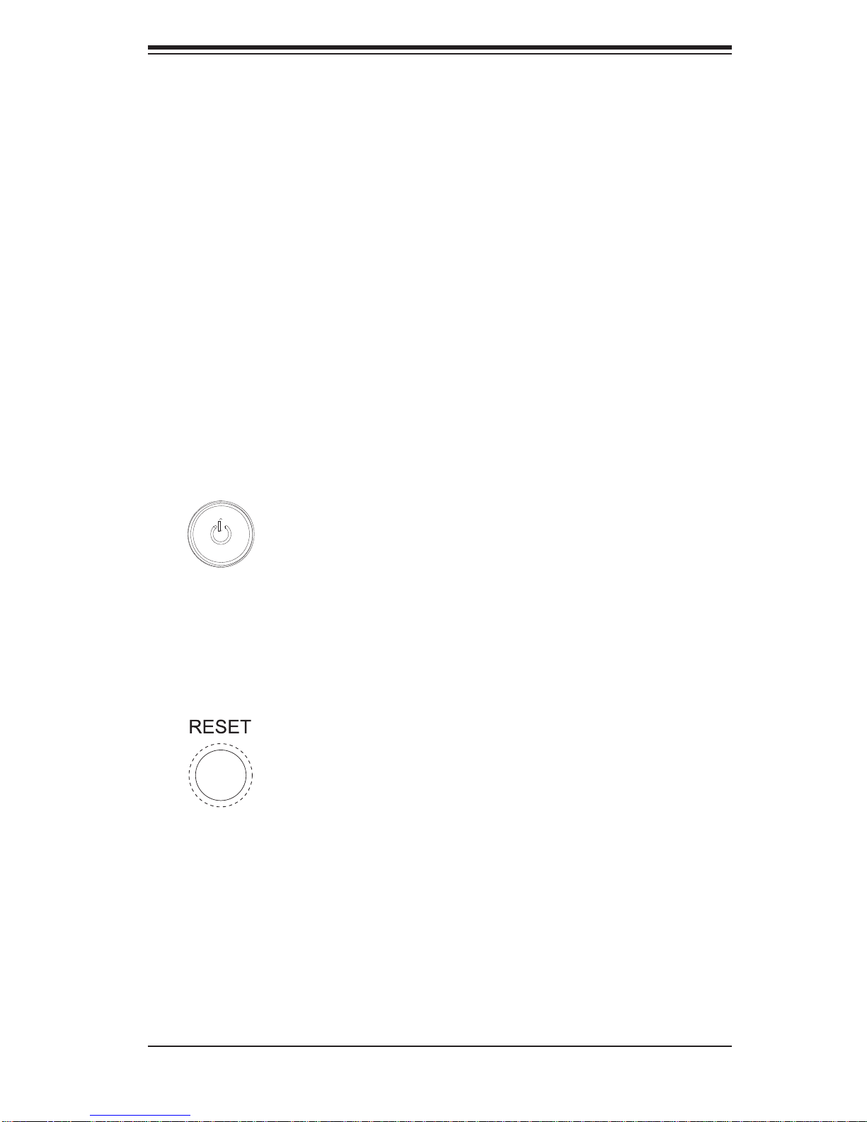
There are two push-buttons located on the front of the chassis: a power on/off
button and a reset button.
Power
This is the main power button, which is used to apply or turn off the main system
power. T urning off system power with this button removes the main power but keeps
standby power supplied to the system.
Reset
Use the reset button to reboot the system.
3-1
Page 26
SuperWorkstation 7046A-6 User's Manual
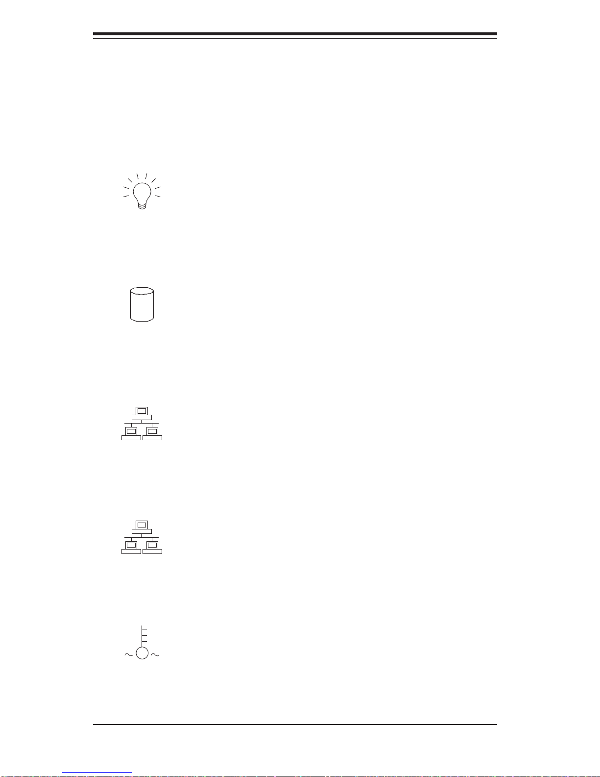
3-3 Control Panel LEDs
The control panel located on the front of the SC743TS-865BP-SQ chassis has
six LEDs that provide you with critical information related to different parts of the
system. This section explains what each LED indicates when illuminated and any
corrective action you may need to take.
Power
Indicates power is being supplied to the system's power supply. This LED should
normally be on when the system is operating.
HDD
Indicates IDE channel activity. On the 7046A-6, this LED indicates SAS/SATA drive
activity when fl ashing.
1
NIC1
Indicates network activity on LAN1 when fl ashing.
2
NIC2
Indicates network activity on LAN2 when fl ashing.
Overheat/Fan Fail
When this LED fl ashes, it indicates a chassis fan failure. When on continuously it
indicates an overheat condition, which may be caused by cables obstructing the
3-2
Page 27

Chapter 3: System Interface
airfl ow in the system or the ambient room temperature being too warm. Check the
routing of the cables and make sure all fans are present and operating normally.
You should also check to make sure that the chassis covers are installed. Finally,
verify that the heatsinks are installed properly (see Chapter 5). This LED will remain
fl ashing or on as long as the indicated condition exists.
Power Fail
Indicates a power supply fan has failed. The power supply module has a redundant
backup fan that will increase its rpm to compensate, but the power module should
be replaced as soon as it's convenient.
3-4 Drive Carrier LEDs
Note: the LEDs of some drive carriers may not function depending on the number
of drives that are supported by the motherboard and/or backplane.
SAS Drives
Green:• When illuminated, the green LED on the front of the SAS drive carrier
indicates drive activity. A connection to the SAS backplane enables this LED to
blink on and off when that particular drive is being accessed.
Red:
• The SES2 backplane activates the red LED to indicate a drive failure.
If one of the SAS drives fail, you should be notifi ed by your system manage-
ment software. Please refer to Chapter 6 for instructions on replacing failed
SAS drives.
SATA Drives
Green:• Each SATA drive carrier has a green LED. When illuminated, this
green LED (on th e front of the SATA drive c arrier) indi cates drive ac tivity. A
conne cti on to th e SATA ba ckp lane ena bles t his LED to b link on a nd of f when
that particular drive is being accessed. Please refer to Chapter 6 for instructions
on replacing failed SATA drives.
Red:
• The red LED to indicate an SATA drive failure. If one of the SATA drives
fail, you should be notifi ed by your system management software. Please refer
to Chapter 6 for instructions on replacing failed SATA drives.
3-3
Page 28

SuperWorkstation 7046A-6 User's Manual
Notes
3-4
Page 29
Chapter 4: System Safety
!
Chapter 4
System Safety
4-1 Electrical Safety Precautions
Basic electrical safety precautions should be followed to protect yourself from
harm and the SuperWorkstation 7046A-6 from damage:
Be aware of the locations of the power on/off switch on the chassis as well
•
as the room's emergency power-off switch, disconnection switch or electrical
outlet. If an electrical accident occurs, you can then quickly remove power from
the system.
Do not work alone when working with high voltage components.
•
Power should always be disconnected from the system when removing or in-•
stalling main system components, such as the serverboard, memory modules
and the CD-ROM and fl oppy drives. When disconnecting power, you should fi rst
power down the system with the operating system and then unplug the power
cords of all the power supply units in the system.
When working around exposed electrical circuits, another person who is familiar
•
with the power-off controls should be nearby to switch off the power if necessary.
Use only one hand when working with powered-on electrical equipment. This
•
is to avoid making a complete circuit, which will cause electrical shock. Use
extreme caution when using metal tools, which can easily damage any electrical
components or circuit boards they come into contact with.
Do not use mats designed to decrease electrostatic discharge as protection from
•
electrical shock. Instead, use rubber mats that have been specifi cally designed
as electrical insulators.
The power supply power cord must include a grounding plug and must be
•
plugged into grounded electrical outlets.
4-1
Page 30
SuperWorkstation 7046A-6 User's Manual
!
This product may be connected to an IT power system. In all cases, make sure •
that the unit is also reliably connected to Earth (ground).
Serverboard Battery:
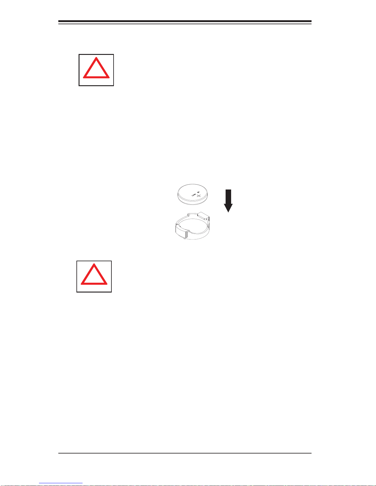
• CAUTION - There is a danger of explosion if the onboard
battery is installed upside down, which will reverse its polarities (see Figure
4-1). This battery must be replaced only with the same or an equivalent type
recommended by the manufacturer. Dispose of used batteries according to the
manufacturer's instructions.
CD-ROM Laser:
• CAUTION - this server may have come equipped with a CD-
ROM drive. To prevent direct exposure to the laser beam and hazardous radiation exposure, do not open the enclosure or use the unit in any unconventional
way.
Mainboard replaceable soldered-in fuses: Self-resetting PTC (Positive Tempera-
•
ture Coeffi cient) fuses on the mainboard must be replaced by trained service
technicians only. The new fuse must be the same or equivalent as the one
replaced. Contact technical support for details and support.
4-2 General Safety Precautions
Follow these rules to ensure general safety:
Keep the area around the SuperWorkstation 7046A-6 clean and free of clut-
•
ter.
The 7046A-6 weighs approximately 64 lbs (29.1 kg.) when fully loaded. When
•
lifting the system, two people at either end should lift slowly with their feet spread
out to distribute the weight. Always keep your back straight and lift with your
legs. Don't use the handles (if installed) to lift the chassis; the handles should
only be used to pull the server out of the rack.
Place the chassis top cover and any system components that have been re-
•
moved away from the system or on a table so that they won't accidentally be
stepped on.
While working on the system, do not wear loose clothing such as neckties and
•
unbuttoned shirt sleeves, which can come into contact with electrical circuits or
be pulled into a cooling fan.
4-2
Page 31
Chapter 4: System Safety
!
Remove any jewelry or metal objects from your body, which are excellent metal •
conductors that can create short circuits and harm you if they come into contact
with printed circuit boards or areas where power is present.
After accessing the inside of the system, close the system back up and secure
•
it to the rack unit with the retention screws after ensuring that all connections
have been made.
4-3 ESD Precautions
Electrostatic Discharge (ESD) is generated by two objects with different electrical
charges coming into contact with each other. An electrical discharge is created to
neutralize this difference, which can damage electronic com ponents and printed
circuit boards. The following measures are generally suffi cient to neutralize this
difference before contact is made to protect your equipment from ESD:
Use a grounded wrist strap designed to prevent static discharge.
•
Keep all components and printed circuit boards (PCBs) in their antistatic bags •
until ready for use.
Touch a grounded metal object before removing the board from the antistatic
•
bag.
Do not let components or PCBs come into contact with your clothing, which may
•
retain a charge even if you are wearing a wrist strap.
Handle a board by its edges only; do not touch its components, peripheral chips,
•
memory modules or contacts.
When handling chips or modules, avoid touching their pins.
•
Put the serverboard and peripherals back into their antistatic bags when not •
in use.
For grounding purposes, make sure your computer chassis provides excellent
•
conductivity between the power supply, the case, the mounting fasteners and
the serverboard.
4-3
Page 32
SuperWorkstation 7046A-6 User's Manual
!
!
4-4 Operating Precautions
Care must be taken to assure that the chassis cover is in place when the 7046A6 is operating to assure proper cooling. Out of warranty damage to the 7046A-6
system can occur if this practice is not strictly followed.
Figure 4-1. Installing the Onboard Battery
LITHIUM BATTERY
BATTERY HOLDER
Please handle used batteries carefully. Do not damage the battery in any way; a
damaged battery may release hazardous materials into the environment. Do not
discard a used battery in the garbage or a public landfi ll. Please comply with the
regulations set up by your local hazardous waste management agency to dispose
of your used battery properly.
4-4
Page 33

Chapter 5: Advanced Serverboard Setup
Chapter 5
Advanced Serverboard Setup
This chapter covers the steps required to install the X8DA6 serverboard into the
chassis, connect the data and power cables and install add-on cards. All serverboard
jumpers and connections are also described. A layout and quick reference chart
are included in this chapter for your reference. Remember to completely close the
chassis when you have fi nished working with the serverboard to better cool and
protect the system.
5-1 Handling the Serverboard
Electrostatic Discharge (ESD) can damage electronic com ponents. To prevent damage to any printed circuit boards (PCBs), it is important to handle them very carefully
(see previous chapter). To prevent the serverboard from bending, keep one hand
under the center of the board to support it when handling. The following measures
are generally suffi cient to protect your equipment from electric static discharge.
Precautions
Use a grounded wrist strap designed to prevent Electrostatic Discharge.•
Touch a grounded metal object before removing any board from its antistatic •
bag.
Handle a board by its edges only; do not touch its components, peripheral chips,
•
memory modules or gold contacts.
When handling chips or modules, avoid touching their pins.
•
Put the serverboard, add-on cards and peripherals back into their antistatic •
bags when not in use.
For grounding purposes, make sure your computer chassis provides excellent
•
conductivity between the power supply, the case, the mounting fasteners and
the serverboard.
5-1
Page 34

SuperWorkstation 7046A-6 User's Manual
Unpacking
The serverboard is shipped in antistatic packaging to avoid electrical static discharge. When unpacking the board, make sure the person handling it is static
protected.
5-2 Serverboard Installation
This section explains the fi rst step of physically mounting the X8DA6 into the
SC743TS-865BP-SQ chassis. Following the steps in the order given will eliminate
the most common problems encountered in such an installation. To remove the
serverboard, follow the procedure in reverse order.
Installing to the Chassis
Access the inside of the system by removing the screws from the back lip of 1.
the top cover of the chassis, then pull the cover off.
Make sure that the I/O ports on the serverboard align properly with their 2.
respective holes in the I/O shield at the back of the chassis.
Carefully mount the serverboard to the serverboard tray by aligning the board 3.
holes with the raised metal standoffs that are visible in the chassis.
Insert screws into all the mounting holes on your serverboard that line up with 4.
the standoffs and tighten until snug (if you screw them in too tight, you might
strip the threads).
Finish by replacing the top cover of the chassis.5.
Note: Metal screws provide an electrical contact to the serverboard ground to
provide a continuous ground for the system.
Warning: To avoid damaging the serverboard and its components, do not apply
any force greater than 8 lbs. per square inch when installing a screw into a mounting hole.
5-2
Page 35

Chapter 5: Advanced Serverboard Setup
5-3 Connecting Cables
Now that the serverboard is installed, the next step is to connect the cables to the
board. These include the data (ribbon) cables for the peripherals and control panel
and the power cables.
Connecting Data Cables
The cables used to transfer data from the peripheral devices have been carefully
routed to prevent them from blocking the fl ow of cooling air that moves through
the system from front to back. If you need to disconnect any of these cables, you
should take care to keep them routed as they were originally after reconnecting
them (make sure the red wires connect to the pin 1 locations). The following data
cables (with their locations noted) should be connected. (See the layout on page
5-9 for connector locations.)
SAS drive data cable (SAS0 ~ SAS7)
•
Control Panel cable (JF1)•
Important! Make sure the the cables do not come into contact with the fans.
Connecting Power Cables
The X8DA6 has a 24-pin primary power supply connector (JPW3) for connection
to the ATX power supply. In addition, two 8-pin processor power connectors (JPW1
and JPW2) must also be connected to your power supply . See Section 5-9 for power
connector pin defi nitions.
Connecting the Control Panel
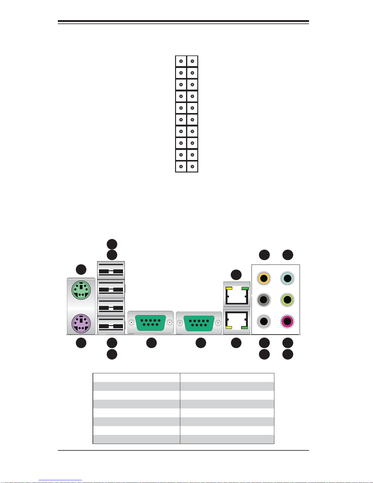
JF1 contains header pins for various front control panel connectors. See Figure 5-1
for the pin locations of the various front control panel buttons and LED indicators.
All JF1 wires have been bundled into a single ribbon cable to simplify this connection. Make sure the red wire plugs into pin 1 as marked on the board. The other
end connects to the Control Panel PCB board, located just behind the system status
LEDs on the chassis. See Chapter 5 for details and pin descriptions.
5-3
Page 36
SuperWorkstation 7046A-6 User's Manual
Figure 5-1. Control Panel Header Pins
20 19
Ground
NMI
5-4 I/O Ports
x (Key)
Power On LED
HDD LED
NIC1 LED
NIC2 LED
OH/Fan Fail LED
Power Fail LED
Ground
Ground
2 1
x (Key)
Vcc
Vcc
Vcc
Vcc
Vcc
Vcc
Reset (Button)
Power (Button)
The I/O ports are color coded in conformance with the PC 99 specifi cation. See
Figure 5-2 below for the colors and locations of the various I/O ports.
Figure 5-2. I/O Ports
6
5
13
16
2
10
1
4
7 8 9
3
1. Keyboard (Purple) 9. LAN1 Port
2. PS/2 Mouse (Green) 10. LAN2 Port
3. USB Port 0 11. Side_Surround (Grey
4. USB Port 1 12. Back_Surround (Black)
5. USB Port 2 13. CEN/LFE (Orange)
6. USB Port 3 14. Microphone-In (Pink)
7. COM1 Port 15. Front (Green)
8. COM2 Port 16. Line In (Blue)
12
11
15
14
5-4
Page 37
Chapter 5: Advanced Serverboard Setup
!
5-5 Processor and Heatsink Installation
When handling the processor package, avoid placing direct pressure on
the label area of the fan.
Notes:
•
Always connect the power cord last and always remove it before adding, removing or changing any hardware components. Make sure that you install the
processor into the CPU socket before you install the CPU heatsink.
If you buy a CPU separately, make sure that you use an Intel-certifi ed multi-
•
directional heatsink only.
Make sure to install the serverboard into the chassis before you install the CPU
•
heatsinks.
When receiving a serverboard without a processor pre-installed, make sure that
•
the plastic CPU socket cap is in place and none of the socket pins are bent;
otherwise, contact your retailer immediately.
Refer to the Sup ermi cro web s ite for upd ates on CPU su ppor t.
•
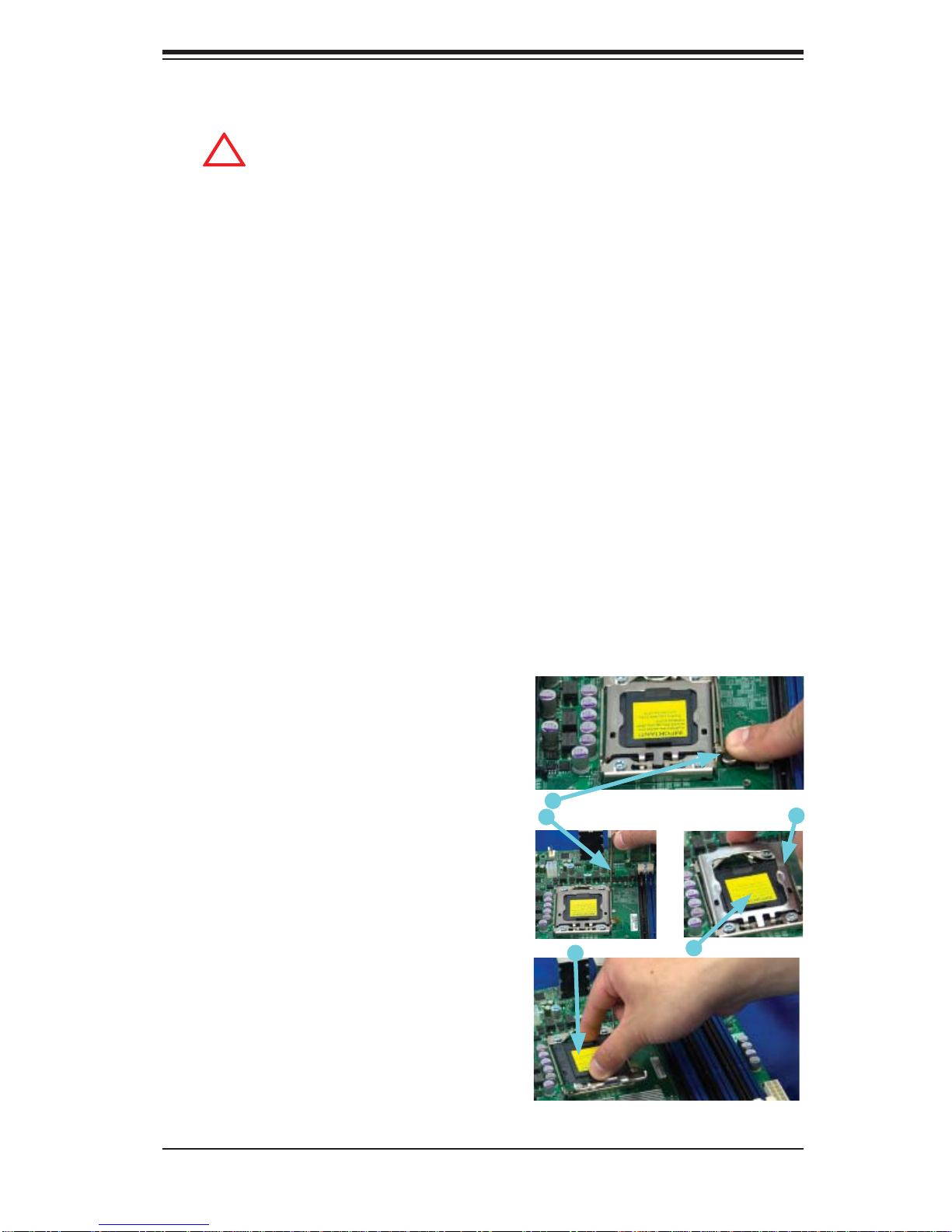
Installing an LGA 1366 Processor
Press the socket clip to release 1.
the load plate, which covers the
CPU socket, from its locking
position.
Socket Clip
Gently lift the socket clip to 2.
open the load plate.
Plastic Cap
Hold the plastic cap at its north 3.
and south center edges to remove it from the CPU socket.
Load Plate
Hold the north & south edges of
the plastic cap to remove it
5-5
Page 38
SuperWorkstation 7046A-6 User's Manual
!
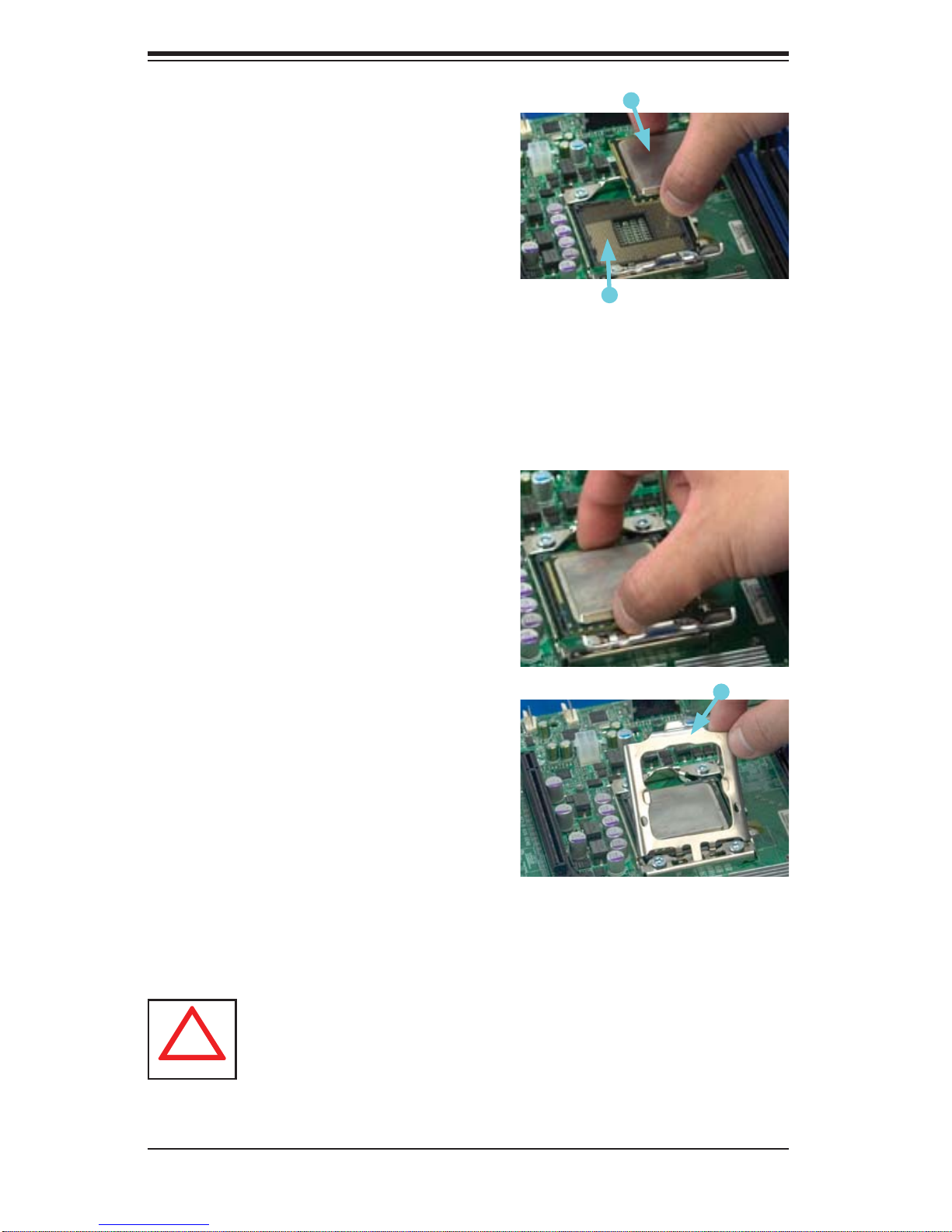
After removing the plastic cap, 1.
using your thumb and the index
fi nger, hold the CPU at the north
and south center edges.
Align the CPU key (the semi-circle 2.
cutout) against the socket key (the
notch below the gold color dot on
the side of the socket).
Once both the CPU and the socket 3.
are aligned, carefully lower the
CPU straight down into the socket.
(Do not rub the CPU against the
surface of the socket or its pins to
avoid damaging the CPU or the
socket.)
With the CPU inside the socket, in-4.
spect the four corners of the CPU
to make sure that it is properly
installed.
CPU
CPU Socket
Once the CPU is securely seated 5.
in the socket, lower the CPU load
plate to the socket.
Use your thumb to gently push the 6.
socket clip down to the clip lock.
Warning: Please save the plastic cap. The motherboard must be shipped
with the plastic cap properly installed to protect the CPU socket pins.
Shipment without the plastic cap properly installed will cause damage
to the socket pins.
Load Plate
5-6
Page 39
Chapter 5: Advanced Serverboard Setup
!
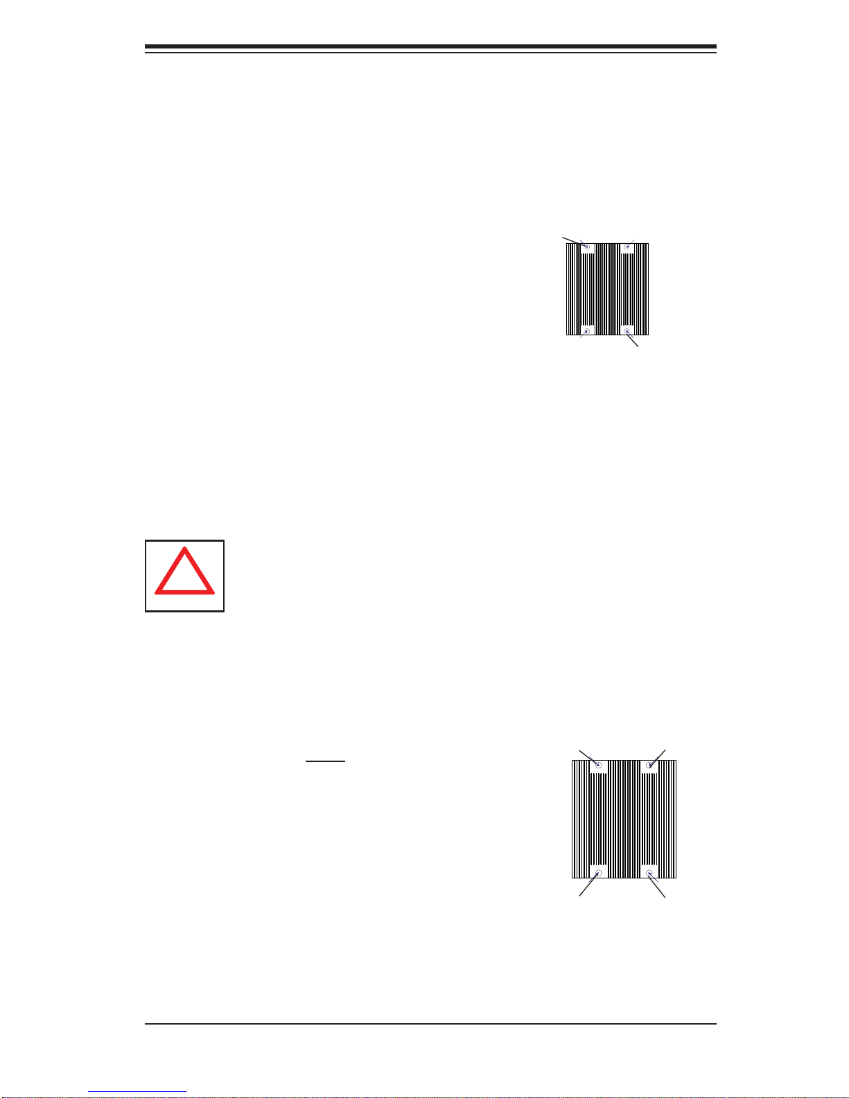
Installation and Removal of the Heatsink
Installing the Heatsink Installation
Do not apply any thermal grease to the 1.
heatsink or the CPU die; the required
amount has already been applied.
Place the heatsink on top of the CPU so 2.
that the four mounting holes are aligned
with those on the retention mechanism.
Screw in two diagonal screws (i.e. the #1 3.
and the #2 screws) until just snug (do not
over-tighten the screws, which may damage the CPU.)
Finish the installation by fully tightening all 4.
four screws.
Uninstalling the Heatsink
Warning: We do not recommend removing the CPU or the heatsink.
However, if you do need to uninstall the heatsink, please follow these
instructions to avoid damaging the CPU or the CPU socket.
Screw #1
Screw #2
Unscrew and remove the heatsink screws 1.
in the sequence shown in the picture on
the right.
Hold the heatsink as shown in the picture 2.
on the right and gently wriggle to loosen
it from the CPU. (Do not use excessive
force when doing this!)
Once the heatsink is loosened, remove it 3.
from the CPU socket.
Clean the surface of the CPU and the 4.
heatsink to get rid of the old thermal
grease. Reapply the proper amount of
thermal grease before you re-install the
heatsink.
5-7
Screw #1
Screw #4
Screw #3
Screw #2
Page 40
SuperWorkstation 7046A-6 User's Manual
5-6 Installing Memory Modules
Note: Check the S uper micro we b site for r ecom mende d memor y mo dules .
CAUTION
Exercise extreme care when installing or removing DIMM
module s to prevent a ny possi ble dam age.
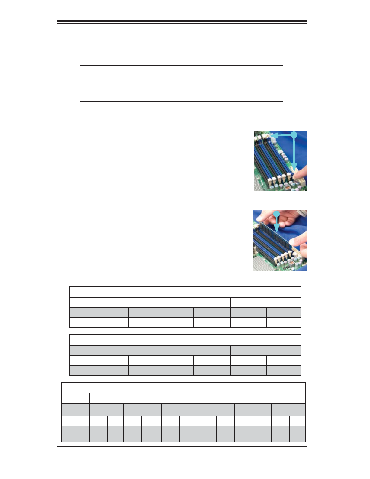
Installing & Removing DIMMs
Press down the release tabs
Insert the desired number of DIMMs into the memory 1.
slots, starting with P1-DIMM 1A. For best performance, please use the memory modules of the same
type and speed in the memory slots as indicated on
the Memory Installation Table (below).
Press down the release tabs on the ends of a mem-2.
ory slot. Insert each DIMM vertically into its slot. Pay
attention to the notch along the bottom of the module
to prevent inserting the DIMM incorrectly.
Insert & press a DIMM into
the slot
Gently press down on the DIMM until it snaps into 3.
place in the slot. Repeat for all modules.
Reverse the steps above to remove the DIMMs from 4.
the serverboard.
Populating Memory with One CPU (CPU1) Installed
O Branch 0 Branch 1 Branch 2
3 DIMMs P1 DIMM1A P1 DIMM2A P1 DIMM3A
6 DIMMs P1 DIMM1A P1 DIMM1B P1 DIMM2A P1 DIMM2B P1 DIMM3A P1 DIMM3B
Populating Memory with One CPU (CPU2) Installed
Branch 0 Branch 1 Branch 2
3 DIMMs P2 DIMM1A P2 DIMM2A P2 DIMM3A
6 DIMMs P2 DIMM1A P2 DIMM1B P2 DIMM2A P2 DIMM2B P2 DIMM3A P2 DIMM3B
Populating Memory with Two CPUs Installed
CPU1 CPU2
Branch 0 Branch 1 Branch 3 Branch 0 Branch 1 Branch 3
6 DIMMs 1A 2A 3A 1A 2A 3A
12
DIMMs
1A 1B 2A 2B 3A 3B 1A 1B 2A 2B 3A 3B
5-8
Page 41
Chapter 5: Advanced Serverboard Setup
Memory Support
The X8DA6 supports up to 96 GB of registered ECC or up to 24 GB of unbuffered
ECC/non ECC DDR3-1333/1066/800 in 12 slots. Memory speed support is dependent on the type of CPU used.
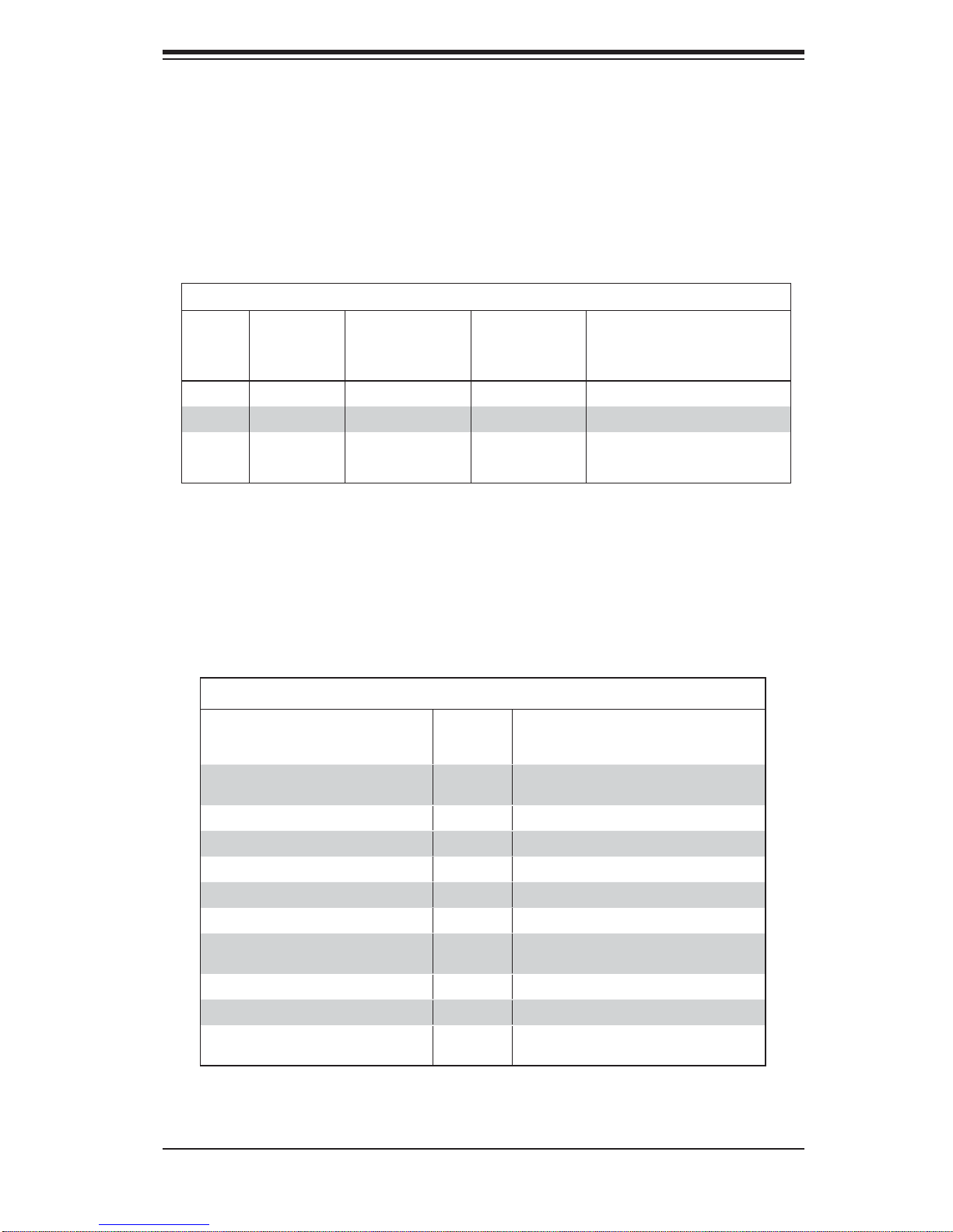
DIMM Module Population Confi guration
For memor y to wor k pro perl y, follow the tab les be low for me mor y inst allati on:
DIMM Population Table
DIMM
Slots
per
Channel
2 1 Reg. DDR3 ECC 800,1066,1333 SR or DR
2 1 Reg. DDR3 ECC 800,1066 QR
2 2 Reg. DDR3 ECC 800,1066 Both SR, Both DR, or Mixed
2 2 Reg. DDR3 ECC 800 QR & SR, QR & DR, or QR only
DIMMs
Populated
per Channel
DIMM Type (Reg.=
Registered)
Speeds (in MHz) Ranks per DIMM (any
combination; SR=Single Rank,
DR=Dual Rank,
QR=Quad Rank)
Note 1: Due to OS limitations, some operating systems may not show more than
4 GB of memory.
Note 2: Due to memory allocation to system devices, the amount of memory that
remains available for operational use will be reduced when 4 GB of RAM is used.
The reduction in memory availability is disproportional. (See the following Memory
Availability Table.)
Possible System Memory Allocation & Availability
System Device Size Physical Memory
Firmware Hub fl ash memory (System
BIOS)
Local APIC 4 KB 3.99 GB
Area Reserved for the chipset 2 MB 3.99 GB
I/O APIC (4 Kbytes) 4 KB 3.99 GB
PCI Enumeration Area 1 256 MB 3.76 GB
PCI Express (256 MB) 256 MB 3.51 GB
PCI Enumeration Area 2 (if needed)
-Aligned on 256-MB boundaryVGA Memory 16 MB 2.85 GB
TSEG 1 MB 2.84 GB
Memory available for the OS & other
applications
1 MB 3.99 GB
512 MB 3.01 GB
Remaining (-Available) (4 GB Total System
Memory)
2.84 GB
5-9
Page 42

SuperWorkstation 7046A-6 User's Manual
5-7 Adding PCI Add-On Cards
The 7046A-6 can accommodate standard size add-on cards populated in all slots
on the X8DA6 serverboard.
Installing an Add-on Card
Begin by removing the PCI slot shield for the slot you wish to populate.1.
Fully seat the card into the riser card slot, pushing down with your thumbs 2.
evenly on both sides of the card.
Finish by using a screw to secure the top of the card shield to the chassis. 3.
The PCI slot shields protect the serverboard and its components from EMI
and aid in proper ventilation, so make sure there is always a shield covering
each unused slot.
5-10
Page 43
5-8 Serverboard Details
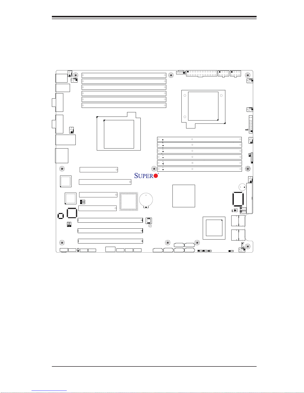
Figure 5-3. X8DA6 Layout
Chapter 5: Advanced Serverboard Setup
FAN5
KB/MS
USB
/2/3
0/1
COM1
COM2
LAN1/2
HD Audio
82574
LAN
CTRL
Audio
CTRL
CD1
82574
LAN
CTRL
JPAC1
FAN6
J27
FAN8 (CPU1 Fan)
JPI1
JL2
CNF2
Slot 7: PCI-E 2.0 x4 in x8
Slot 6: PCI-E 2.0 x16
Slot 5: PCI-E 2.0 x4 in x8
JI2C1
JI2C2
Slot 4: PCI-E x4 in x8 Slot
Slot 3: PCI-X 133MHz
Slot 2: PCI-X 133/100MHz
Slot 1: PCI-X 133/100MHz
CNF1
USB8
P1-DIMM3A
P1-DIMM3B
P1-DIMM2A
P1-DIMM2B
P1-DIMM1A
P1-DIMM1B
CPU1
Intel
ICH10R
USB6/7 USB4/5
JLPC80
Battery
BIOS
X8DA6
JBT1
JPI2C1
Rev. 1.0
Intel 5520
IOH-36D
I-SATA5
I-SATA4
I-SATA1I-SATA0 I-SATA3
I-SATA2
JPW3
CPU2
P2-DIMM1B
P2-DIMM1A
P2-DIMM2B
P2-DIMM2A
P2-DIMM3B
P2-DIMM3A
JPT1
JWD1
LSI
2008
SAS CTRL
JL1
JPW2
Speaker
JPS1
JPW1
S/IO
JIBTN1
LED1
T-SGPIO2
SAS0~3
SAS4~7
JWOL
FAN1
FAN7/CPU2
LE1
JF1
FAN2
JOH1
JD1
FAN3
FLOPPY
T-SGPIO1
FAN4
Notes:
1. To prevent damage to your power supply or motherboard, use a power supply that
contains a 24-pin and two 8-pin power connectors. Be sure to connect these power
connectors to the 24-pin and the two 8-pin power connectors on the serverboard
to supply adequate power. Failure to do so will void the manufacturer warranty on
your power supply and serverboard.
2. Jumpers JPL1/JPL2 are available for the PCB Rev. 1.31 or a later vision of the
serverboard only.
5-11
Page 44

SuperWorkstation 7046A-6 User's Manual
X8DA6 Quick Reference
Jumper Description Default Setting
JBT1 CMOS Clear (See Section 5-10)
2
JI
C1/JI2C2 SMB (I2C) to PCI-X Slots Pins 2-3 (Disabled)
JL2 Audio Mode Select Off (HD Mode)
JPAC1 Audio Enable/Disable Pins 1-2 (Enabled)
JPL1/JPL2 LAN 1/2 En/Dis (For PCB Rev.1.31 or later) Pins 1-2 (Enabled)
JPI1 CNF1/CNF2 (1394a_1/2) Enable/Disable Pins 1-2 (Enabled)
JPS1 SAS Enable/Disable Pins 1-2 (Enabled)
JWD1 Watch Dog Pins 1-2 (Reset)
Connector Description
Audio/CD1/J27 Audio Input_Output_Mic/CD-ROM/HD Audio Headers
CNF1/ CNF2 IEEE 1394a (FireWire) Connectors 1/2
COM1/COM2 COM1/COM2 Serial Ports
FAN 1-8 System/CPU Fan Headers (Fans 7~8: CPU Fans)
Floppy Floppy Disk Drive Connector
JD1 Speaker/Power LED Header
JF1 Control Panel Header
JIBTN1 RAIDKey for RAID5 Support
JL1 Chassis Intrusion Header
JOH1 Overheat LED Header
2
JPI
C Power Supply (System Management Bus) I2C Header
JPW1/JPW2 8-pin Processor Power Connectors
JPW3 24-pin ATX Main Power Connector
JWOL Wake-On-LAN Header
LAN1/2 Gigabit Ethernet (RJ45) Ports
I-SATA0 ~ I-SATA5 Intel (ICH10R) SATA Ports
SAS 0~3, 4~7 SAS Ports
T-SGPIO-1/T-SGPIO-2 Serial General Purpose Input/Output Headers
USB 0/1/2/3 Universal Serial Bus (USB) Ports
USB 4/5, 6/7, 8 Front Panel Ac ces sible U SB He aders
LED Description
LE1 O nboar d Stan dby PWR war ning LED I ndic ator
LED1 SAS LED Ind icato r
5-12
Page 45
Chapter 5: Advanced Serverboard Setup
5-9 Connector Defi nitions
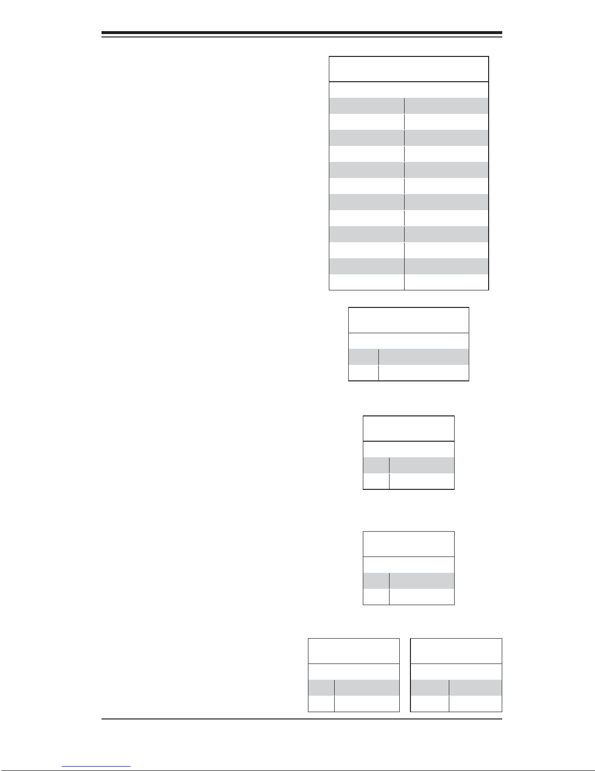
Main ATX Power Supply
Connector
The primary power supply connector
(JPW3) meets the SSI (Superset ATX)
24-pin specifi cation. Refer to the table
on the right for the pin defi nitions of
the ATX 24-pin power connector. You
must also connect the 8-pin (JPW1
and JPW2) power connectors to your
power supply (see below).
Processor Power Connector
JPW1 and JPW2 must also be connected to the power supply to provide
power for the processor. See the table
on the right for pin defi nitions.
ATX Power 24-pin Connector
Pin Defi nitions
Pin# Defi nition Pin # Defi nition
13 +3.3V 1 +3.3V
14 -12V 2 +3.3V
15 COM 3 COM
16 PS_ON 4 +5V
17 COM 5 COM
18 COM 6 +5V
19 COM 7 COM
20 Res (NC) 8 PWR_OK
21 +5V 9 5VSB
22 +5V 10 +12V
23 +5V 11 +12V
24 COM 12 +3.3V
8-pin (+12V) Processor Power
Pin Defi nitions
Pins Defi nition
1 - 4 Ground
5 - 8 +12V
Required Connection
Power Button
The connection for the power button
is on pins 1 and 2 of JF1. The chassis power button should be connected
here. See the table on the right for pin
defi nitions.
Reset Connector
The reset header is located on pins 3
and 4 of JF1. Attach the reset switch
on the computer chassis to these
pins. See the table on the right for
pin defi nitions.
Overheat/Fan Fail LED (OH)
Connect an LED to pins 7 and 8 of
JF1 to provide advanced warning of
chassis overheating or fan failure. See
the tables on the right details..
Pin# Defi nition
1 PW_ON
2 Ground
Pin# Defi nition
3 Reset
4 Ground
OH/Fan Fail LED
Pin Defi nitions
Pin# Defi nition
7 Vcc
8 Ground
Power Button
Pin Defi nitions
Reset Button
Pin Defi nitions
OH/Fan Fail LED
Status
State Message
Solid Overheat
Blinking Fan Fail
5-13
Page 46

SuperWorkstation 7046A-6 User's Manual
NIC1 (GLAN) LED
The LED connections for the GB LAN
port are on pins 11 and 12 of JF1. Attach an LED cable to display network
activity. See the table on the right for
pin defi nitions.
HDD LED
The HDD LED connection is located
on pins 13 and 14 of JF1. This LED
is used to display all IDE and SATA
activity. See the table on the right for
pin defi nitions.
NIC1 LED
Pin Defi nitions
Pin# Defi nition
11 Vcc
12 Ground
HDD LED
Pin Defi nitions
Pin# Defi nition
13 Vcc
14 HD Active
Power On LED
The Power On LED connector is located on pins 15 and 16 of JF1 (use
JLED for a 3-pin connector). This
connection is used to provide LED
indication of power being supplied to
the system. See the table on the right
for pin defi nitions.
Chassis Intrusion
The Chassis Intrusion header is designated JL1. Attach an appropriate
cable from the chassis to inform you
of a chassis intrusion when the chassis is opened
ATX PS/2 Keyboard and PS/2
Mouse Ports
The ATX PS/2 keyboard and the PS/2
mouse are located on the I/O backpanel. The mouse port is above the
keyboard port. See the table on the
right for pin defi nitions.
Power LED
Pin Defi nitions
Pin# Defi nition
15 5V Stby
16 Control
Chassis Intrusion
Pin Defi nitions
Pin# Defi nition
1 Intrusion Input
2 Ground
PS/2 Keyboard and
Mouse Port Pin
Defi nitions
Pin# Defi nition
1 Data
2NC
3 Ground
4 VCC
5 Clock
6NC
5-14
Page 47
Fan Headers
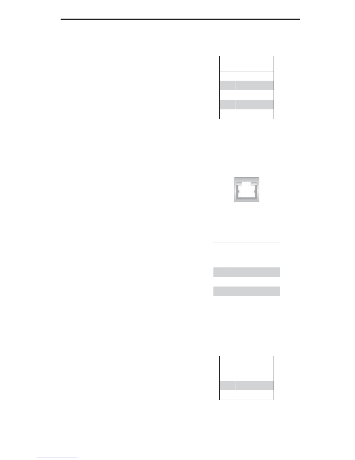
The X8DA6/X8DAE has six fan headers (Fan1 to Fan6) and two CPU fan
headers (Fan7/Fan8). All these 4-pin
fans headers are backward compatible with traditional 3-pin fans. However, fan speed control is available for
4-pin fans only. The fan speeds are
controlled by a Hardware Monitoring
setting in the BIOS. (The Default setting is Disabled.) See the table on the
right for pin defi nitions.
LAN1/LAN2 (Ethernet Ports)
Chapter 5: Advanced Serverboard Setup
Fan Header
Pin Defi nitions
Pin# Defi nition
1 Ground (Black)
2 +12V (Red)
3 Tachometer
4 PWM Control
Two Ethernet ports are located on the
I/O backplane. These ports accept
RJ45 type cables.
Wake-On-LAN
The Wake-On-LAN header is designated JWOL on the serverboard. See
the table on the right for pin defi ni-
tions. You must also have a LAN card
with a Wake-On-LAN connector and
cable to use this feature.
Wake-On-Ring
The Wake-On-Ring header is designated JWOR. This function allows
your computer to receive and be
"awakened" by an incoming call when
in the suspend state. See the table on
the right for pin defi nitions. Y ou must
also have a WOR card and cable to
use this feature.
Wake-On-LAN
Pin Defi nitions
Pin# Defi nition
1 +5V Standby
2 Ground
3 Wake-up
Wake-On-Ring
Pin Defi nitions
Pin# Defi nition
1 Ground (Black)
2 Wake-up
5-15
Page 48
SuperWorkstation 7046A-6 User's Manual
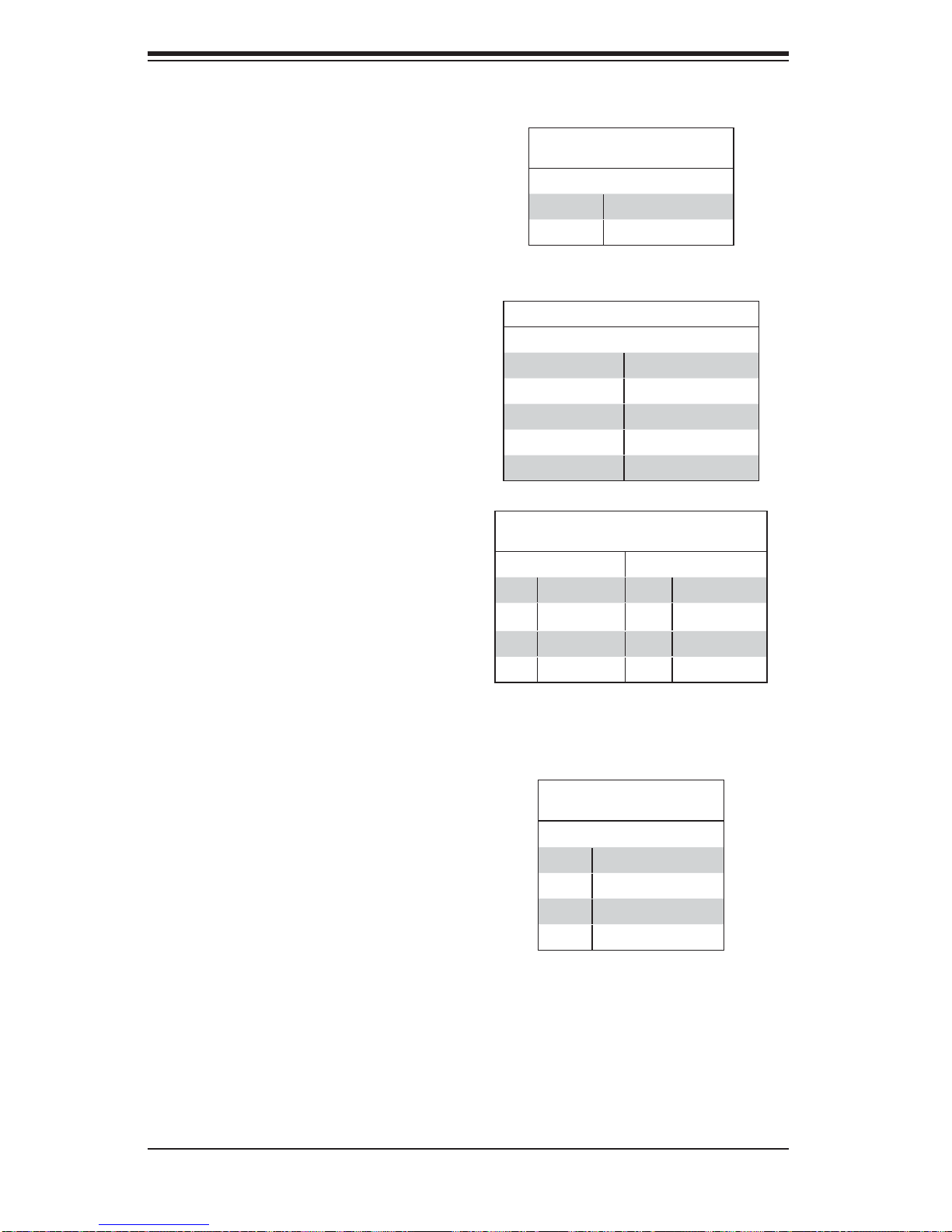
Speaker
On the JD1 header, pins 3~4 are used
for the internal speaker. Close pins
3~4 to use the onboard speaker. If
you wish to use an external speaker,
connect the speaker cable to pins
1~4. See the table on the right for pin
defi nitions.
Serial Ports
Two serial ports are included on the
H8DA6. See the table on the right for
pin defi nitions.
SGPIO Header
Two SGPIO (Serial General Purpose
Input/Output) headers are designated
SGPIO0 and SGPIO1. These headers are used to communicate with
the system's enclosure management
chip. See the table on the right for pin
defi nitions.
Speaker Connector
Pin Defi nitions
Pin Setting Defi nition
Pins 3~4 Internal Speaker
Pins1~4 External Speaker
Serial Port Pin Defi nitions
Pin # Defi nition Pin # Defi nition
1 DCD 6 DSR
2 RXD 7 RTS
3 TXD 8 CTS
4 DTR 9 RI
5 Ground 10 NC
SGPIO Header
Pin Defi nitions
Pin# Defi nition Pin Defi nition
1NC 2 NC
3 Ground 4 DATA Out
5 Load 6 Ground
7 Clock 8 NC
NC = No Connection
CD and Audio FP
A 4-pin CD header (CD-IN) and an
auxilia ry header (Au dio FP) allow you
to use the onboard sound for audio
CD playba ck. Co nnect an au dio cab le
from your CD drive to the header that
fi ts your cable's connector. Only one
header c a n be us ed at a t im e. Se e th e
table at r ight fo r pin defi nitions.
RAIDKey (Optional)
A RAIDKey header, located at JIBTN1,
provides RAID function support to
enhance the performance of Intel
HostRAID and LSI Mega-RAID. (AOCIMRRAkey-LSI-2008 is optional.)
5-16
Audio Input CD Header
Pin Defi nitions
Pin# Defi nition
1 Left Stereo Signal
2 Ground
3 Ground
4 Right Stereo Signal
Page 49
Front Panel Audio Control
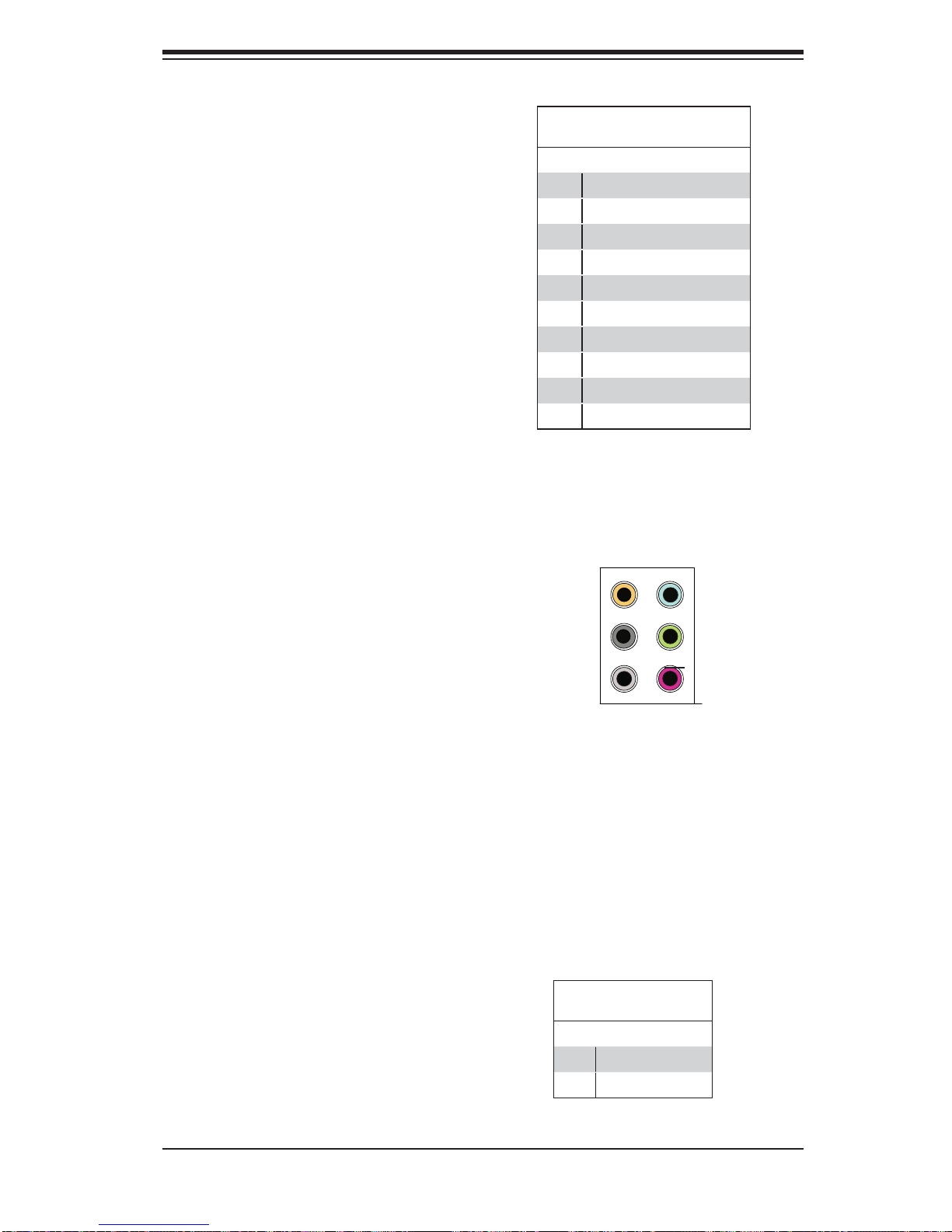
When front panel headphones are
plugged in, the back panel audio output
is disabled. This is done through the FP
Audio header (Audio FP). If the front
panel interface card is not connected to
the front panel audio header, jumpers
should be installed on pin pairs 1-2,
5-6, and 9-10 of the Audio FP header.
If these jumpers are not installed, the
back panel line out connector will be
disabled, and pin 1 of the microphone
in will be left fl oating, which can lead
to excessive back panel microphone
noise and crosstalk. See the table at
right for pin defi nitions.
Chapter 5: Advanced Serverboard Setup
Front Panel Audio (HD Rev. 1.2)
Pin Defi nitions
Pin# Defi nition
1 MIC left channel
2 Ground
3 MIC right channel
4 Front panel audio detect
5 Line_out right channel
6 MIC jack detect
7 Front audio jack detect
8 Key
9 Line_out left channel
10 Line_out jack detect
High Defi nition Audio (HDA)
The X8DA6 features a 7.1+2 Channel
High Defi nition Audio (HDA) codec that
provides 10 DAC channels, simultaneously supporting 7.1 sound playback
and two channels of independent stereo sound output (multiple streaming)
through the front panel stereo out via
the front L&R, rear L&R, center and
subwoofer speakers. This feature is
activated with the software included in
the CD-ROM that came with your motherboard. Sound is output through the
Line In, Line Out and MIC jacks.
Overheat/Fan Fail LED (JOH1)
The JOH1 header is used to connect
an LED to provide warnings of chassis overheat. This LED will also blink
to indicate a fan failure. Refer to the
table on right for pin defi nitions.
Orange:
CEN/LFE
Black: Back
Surround
Grey: Side
Surround
Pin# Defi nition
1 5vDC
2 OH Active
Blue: Line-In
Green:Front
Pink: Mic-In
Overheat LED
Pin Defi nitions
5-17
Page 50
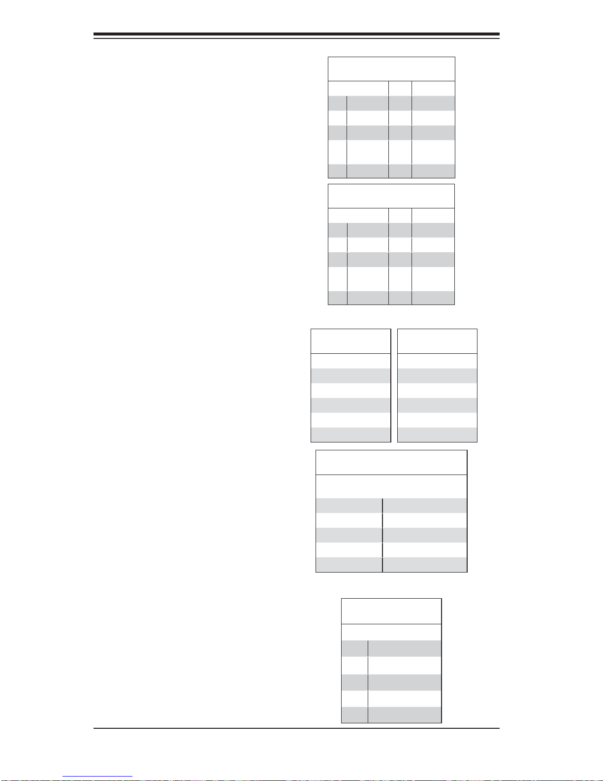
SuperWorkstation 7046A-6 User's Manual
IEEE 1394 Connectors
Connectors CNF1 and CNF2 provide
connectivity for IEEE 1394 (FireWire)
devices. See the tables on the right
for pin defi nitions.
CNF1
Pin Defi nitions
Pin# Defi n. Defi n
1 PTPA0+ 2 PTPA03 GND 4 GND
5 PTPB0+ 6 PTPB07 PWR
1394
Pin# Defi n. Defi n
1 PTPA1+ 2 PTPA13 GND 4 GND
5 PTPB1+ 6 PTPB17 PWR
1394
8 PWR
1394
10 ZX
CNF2
Pin Defi nitions
8 PWR
1394
10 ZY
Universal Serial Bus (USB)
Four Universal Serial Bus ports (USB
0~USB 3) are located on the I/O
back panel. An addition five USB
connections (USB 4/5, 6/7, 8) on
the serverboard provide front chassis access (cables are not included).
See the tables on the right for pin
defi nitions.
Power SMB (I2C) Connector
The Power System Management
2
Bus (I
C) connector (JPI2C) monitors
power supply, fan and system temperatures. See the table on the right
for pin defi nitions.
Back Panel USB
(USB 0/1/2/3)
Pin# Defi nitions
1 +5V
2 PO3 PO+
4 Ground
5 N/A
Front Panel USB
Pin Defi nitions (USB4/5/6/7)
USB 4/6
Pin # Defi nition
1 +5V 1 +5V
2 PO- 2 PO3 PO+ 3 PO+
4 Ground 4 Ground
5 Key 5 No connection
PWR SMB
Pin Defi nitions
Pin# Defi nition
1 Clock
2 Data
3 PWR Fail
4 Ground
5 +3.3V
Front Accessible
(USB 8)
Pin# Defi nitions
1 Vcc
2 Data3 Data+
4 Ground
5 N/A
USB 5/7
Pin # Defi nition
5-18
Page 51
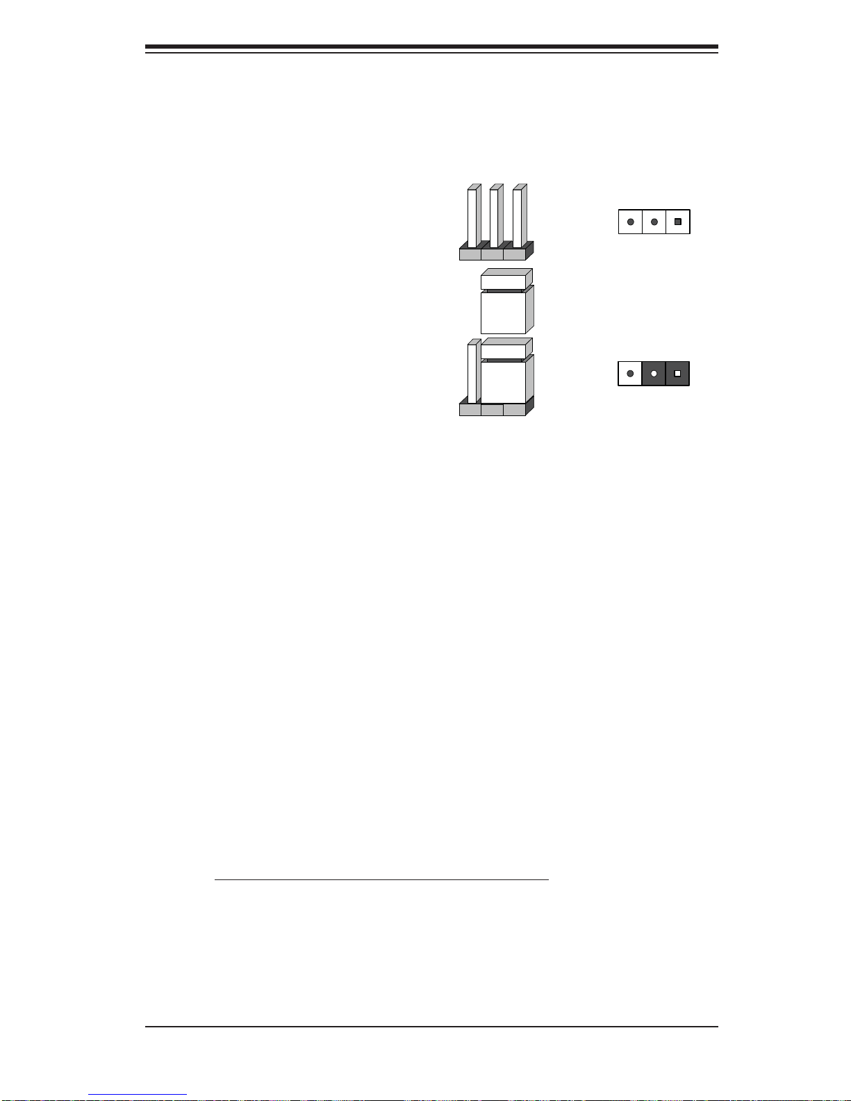
5-10 Jumper Settings
Explanation of Jumpers
To modify the operation of the
serverboard, jumpers can be used
to choose between optional settings.
Jumpers create shorts between two
pins to change the function of the connector. Pin 1 is identifi ed with a square
solder pad on the printed circuit board.
See the serverboard layout pages for
jumper locations.
Note: On a two-pin jumper, "Closed"
means the jumper is on both pins and
"Open" means the jumper is either on
only one pin or completely removed.
Chapter 5: Advanced Serverboard Setup
3 2 1
Connector
Pins
Jumper
3 2 1
Setting
CMOS Clear
JBT1 is used to clear CMOS (which will also clear any passwords). Instead of pins,
this jumper consists of contact pads to prevent accidentally clearing the contents
of CMOS.
To clear CMOS,
First power down the system and unplug the power cord(s).1.
With the power disconnected, short the CMOS pads with a metal object such 2.
as a small screwdriver.
Remove the screwdriver (or shorting device).3.
Reconnect the power cord(s) and power on the system.4.
Note: Do not use the PW_ON connector to clear CMOS.
5-19
Page 52
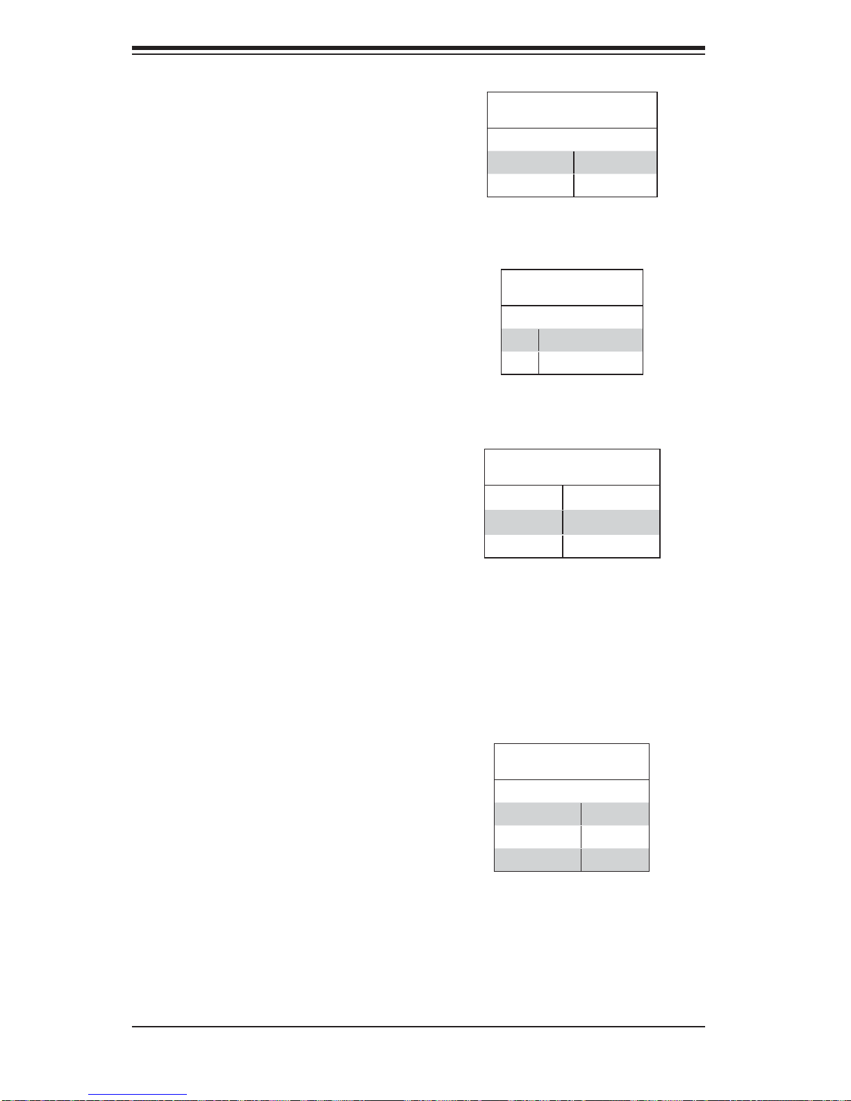
SuperWorkstation 7046A-6 User's Manual
LAN1/LAN2 Enable/Disable
Change the setting of jumper JPL1 or
JPL2 to enable or disable the LAN1 and
LAN2 Ethernet ports, respectively. See
the table on the right for jumper settings. The default setting is enabled.
LAN1/LAN2 Enable/Disable
Jumper Settings
Jumper Setting Defi nition
Pins 1-2 Enabled
Pins 2-3 Disabled
Audio Enable/Disable
JPAC enables or disables the onboard
audio connections. See the table on the
right for jumper settings. The default
setting is Enabled.
SMBus to PCI Slots
Jumpers JI
2
C1 and JI2C2 allow you to
connect the PCI slots to the System
Management Bus (I
2
C). The default
setting is disabled. See the table on the
right for jumper settings.
Watch Dog Enable/Disable
JWD controls the Watch Dog function.
Watch Dog is a system monitor that
can reboot the system when a software application hangs. Jumping pins
1-2 (the default setting) will cause WD
to reset the system if an application
hangs. Jumping pins 2-3 will generate
a non-maskable interrupt signal for the
application that hangs. See the table on
the right for jumper settings. Watch Dog
must also be enabled in BIOS.
Audio Enable/Disable
Jumper Settings
Pin# Defi nition
1-2 Enabled
2-3 Disabled
SMBus to PCI Slots
Jumper Settings
2
JI
C1/ JI2C2 Setting
Pins 1-2 Enabled
Pins 2-3 Disabled
Watch Dog
Jumper Settings (JWD)
Jumper Setting Defi nition
Pins 1-2 Reset
Pins 2-3 NMI
Open Disabled
Note: When enabled, the user needs to
write their own application software in
order to disable the Watch Dog Timer.
5-20
Page 53
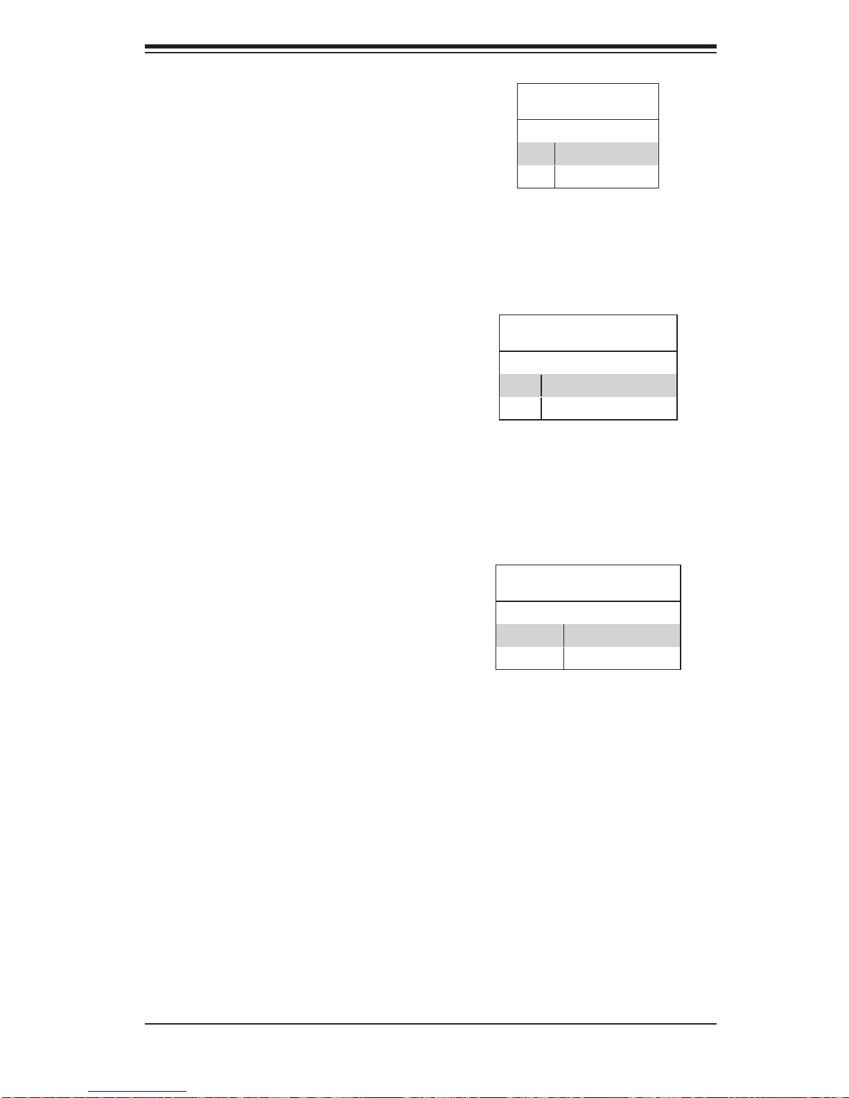
Chapter 5: Advanced Serverboard Setup
1394a (FireWire) Enable/Disable
JPI1 allows the user to use the onboard
IEEE CNF1 and CNF2 connections.
Close pins 1-2 to enable FireWire use.
The default setting is enabled.
SAS Enable/Disable
Jumper JPS1 allows you to enable or
disable the onboard SAS ports. The
default setting is pins 1-2 to enable
the ports. See the table on the right for
jumper settings.
1394a Enable/Disable
Jumper Settings
Pin# Defi nition
1-2 Enabled
2-3 Disabled
SAS Enable/Disable
Jumper Settings
Jumper Setting Defi nition
1-2 SAS Enabled
2-3 SAS Disabled
Audio Mode Select
Jumper JL2 allows you to select the
Audio mode. The choices are AC '97
Audio and HD (High-Defi nition) Audio.
The default setting is open to use HD
Audio. See the table on the right for
jumper settings.
Audio Mode Select
Jumper Settings
Jumper Setting Defi nition
Closed AC'97 Audio
Open HD Audio
5-21
Page 54
SuperWorkstation 7046A-6 User's Manual
5-11 Onboard Indicators
LAN1/2 LEDs
The Ethernet ports (located beside
the VGA port) have two LEDs. On
each port, one LED indicates activity
while the other LED may be green,
amber or off to indicate the speed of
the connection. See the table on the
right for the functions associated with
the connection speed LED.
Onboard Power LED (LE1)
An Onboard Power LED is located at
LE1 on the serverboard. When LE1
is on, the system is on. Make sure
to disconnect the power cable before
removing or installing components.
See the table on the right for more
details.
(Connection Speed Indicator)
LED Color Defi nition
Off No Connection or 10 Mb/s
Green 100 Mb/s
Amber 1 Gb/s
Onboard PWR LED Indicator (LE1)
LED Color Defi nition
Off System Off (PWR cable
Green System On
Green:
Flashing
Quickly
Green:
Flashing
Slowly
LAN1/2 LED
LED Settings
not connected)
ACPI S1 State
ACPI S3 (STR) State
SAS LED Indicator
An onboard SAS LED is located at
LED1. When this LED is on, the SAS
ports are working properly.
5-22
Page 55
Chapter 5: Advanced Serverboard Setup
5-12 Floppy, SAS and SATA Ports
Floppy Connector
The fl oppy connector is located be-
tween the COM port and FireWire
headers on the motherbo a rd. See the
table o n the ri ght for p in defi nitions.
Note the following when connecting
the fl oppy cable:
•
The fl oppy disk drive cable has
seven tw isted wi res.
A red mark on a wire typically des-
•
ignates th e loc ation of p in 1.
A single fl oppy disk drive ribbon
•
cable has 34 wires and two connectors to provide for two fl oppy
disk drives. The connector with
twisted wires always connects to
drive A, and the connector that
does not have twisted wires always connects to drive B.
Pin# Defi nition Pin # Defi nition
1 Ground 2 FDHDIN
3 Ground 4 Reserved
5 Key 6 FDEDIN
7 Ground 8 Index
9 Ground 10 Motor Enable
11 Ground 12 Drive Select B
13 Ground 14 Drive Select B
15 Ground 16 Motor Enable
17 Ground 18 DIR
19 Ground 20 STEP
21 Ground 22 Write Data
23 Ground 24 Write Gate
25 Ground 26 Track 00
27 Ground 28 Write Protect
29 Ground 30 Read Data
31 Ground 32 Side 1 Select
33 Ground 34 Diskette
Floppy Drive Connector
Pin Defi nitions
SATA Ports
Six Serial ATA (SATA) ports (I-SATA
0~5) are located on the serverboard to
provide serial link connections. Serial
Link connections provide faster data
transmission than those of the traditional Parallel ATA. These SATA ports
are supported by the Intel ICH10R
Chip (South Bridge). See the table on
the right for pin defi nitions.
Pin # Defi nition
1 Ground
2 TXP
3 TXN
4 Ground
5 RXN
6 RXP
7 Ground
SATA Port
Pin Defi nitions
SAS Ports
An LSI 2008 SAS2 controller provides eight SAS ports on the X8DA6. T o confi gure
LSI SAS R A ID set t ings , plea se refe r to th e LSI SAS RAI D Use r Gui de po sted o n
our Web site @http://www.supermicro.com/support/manuals/.
5-23
Page 56
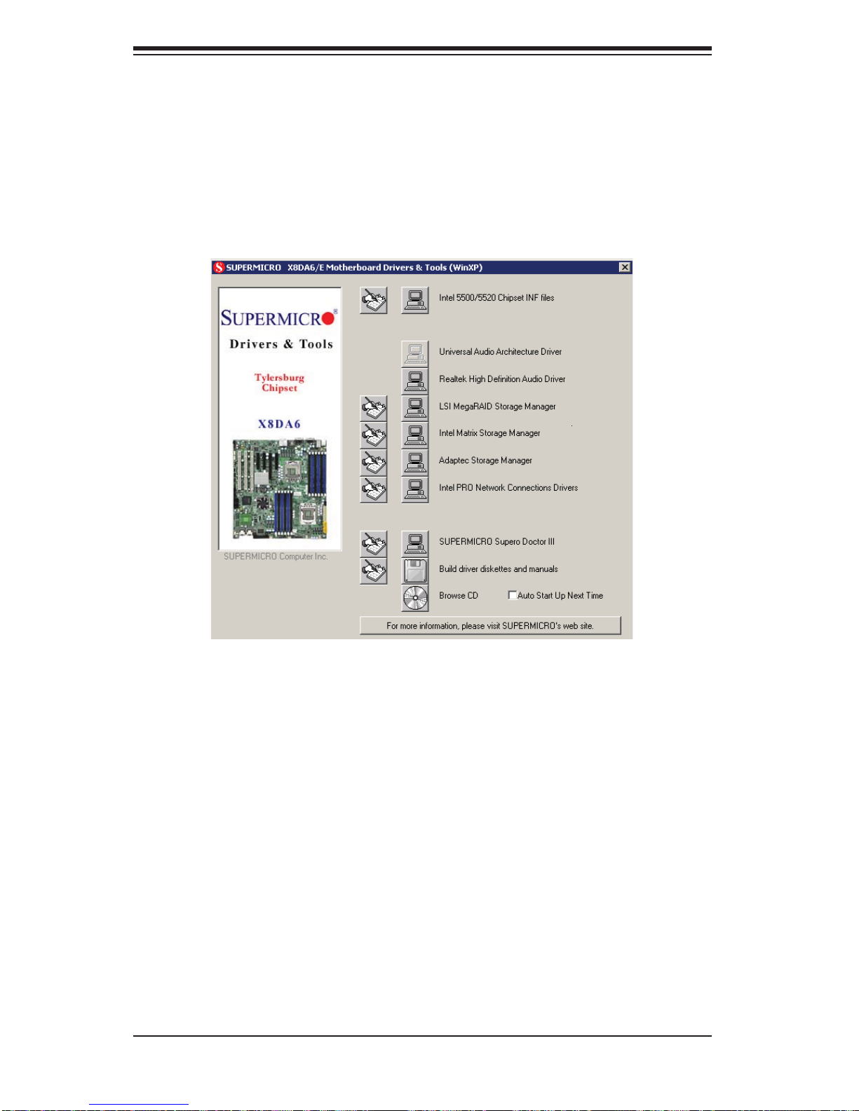
SuperWorkstation 7046A-6 User's Manual
5-13 Installing Additional Drivers
Afte r you've inst alled th e Windows O perati ng System, a sc reen as sho wn below
will app ear. Yo u are ready t o instal l soft ware p rogra ms and dr ivers th at have not
yet been inst al led. To install t hes e sof t war e pro gr ams an d dr iver s, c lic k the i co ns
to the ri ght of the se items .
Driver/Tool Installation Display Screen
Note: Click the icons showing a hand writing on the paper to view the readme fi les
for each item. Click a computer icon to the right of an item to install an item (from
top to the bottom) one at a time. After installing each item, you must re-boot
the system before proceeding with the next item on the list. The bottom icon
with a CD on it allows you to view the entire contents of the CD.
5-24
Page 57
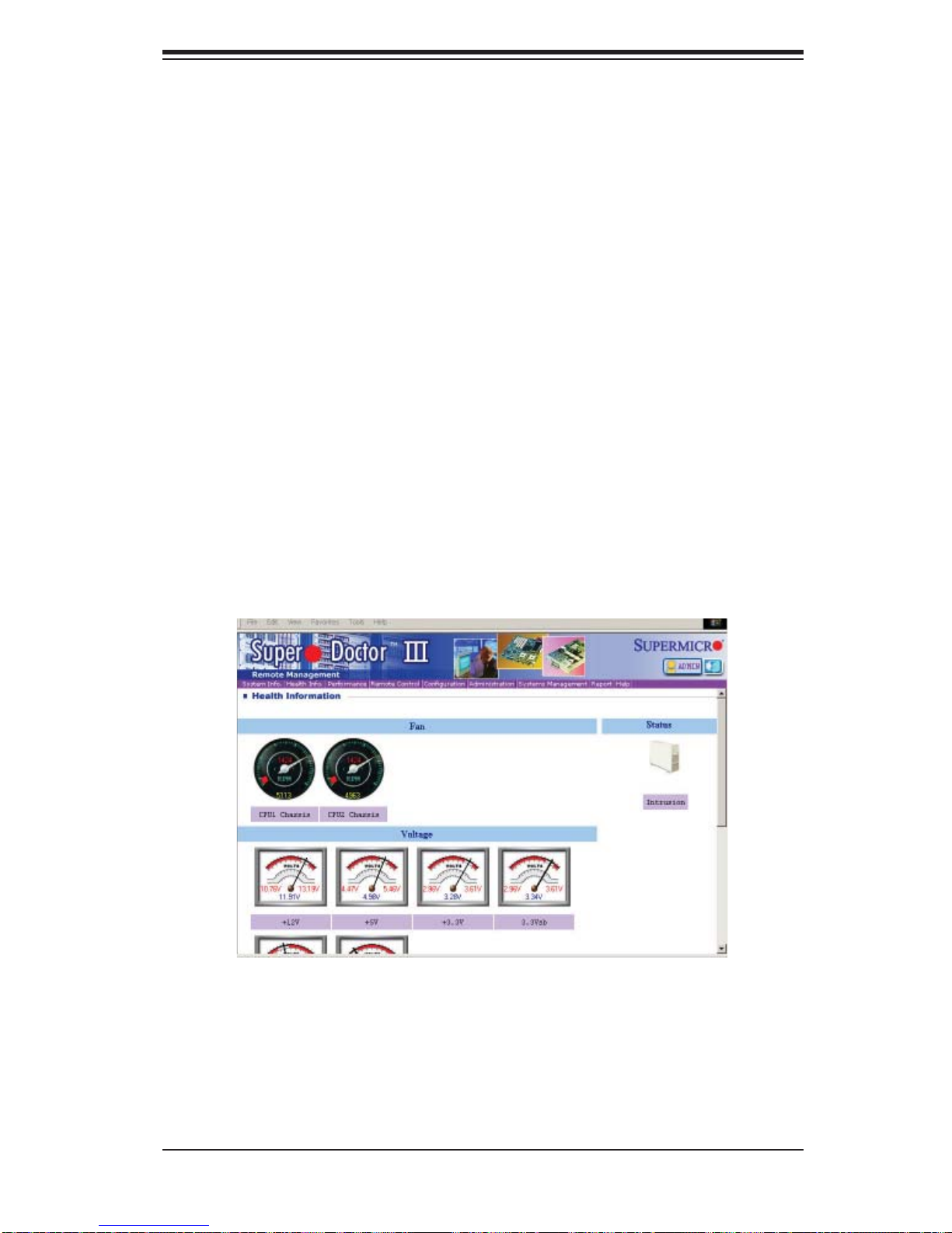
Chapter 5: Advanced Serverboard Setup
5-14 Supero Doctor III
The Supero Doctor III program is a Web-based management tool that supports
remote management capability. It includes Remote and Local Management tools.
The local management is called the SD III Client. The Supero Doctor III program
included on the CDROM that came with your motherboard allows you to monitor
the environment and operations of your system. Supero Doctor III displays crucial
system information such as CPU temperature, system voltages and fan status. See
the Figure below for a display of the Supero Doctor III interface.
Notes: The default User Name and the Password are ADMIN.
In the Windows OS environment, the Supero Doctor III settings take precedence
over the BIOS settings. When fi rst installed, Supero Doctor III adopts the tem-
perature threshold settings previously set in the BIOS. Any subsequent changes
to these thresholds must be made within Supero Doctor, since the SD III settings
override the BIOS settings. For the Windows OS to adopt the BIOS temperature
threshold settings, please change the SDIII settings to be the same as those set
in the BIOS.
Supero Doctor III Interface Display Screen-I (Health Information)
5-25
Page 58
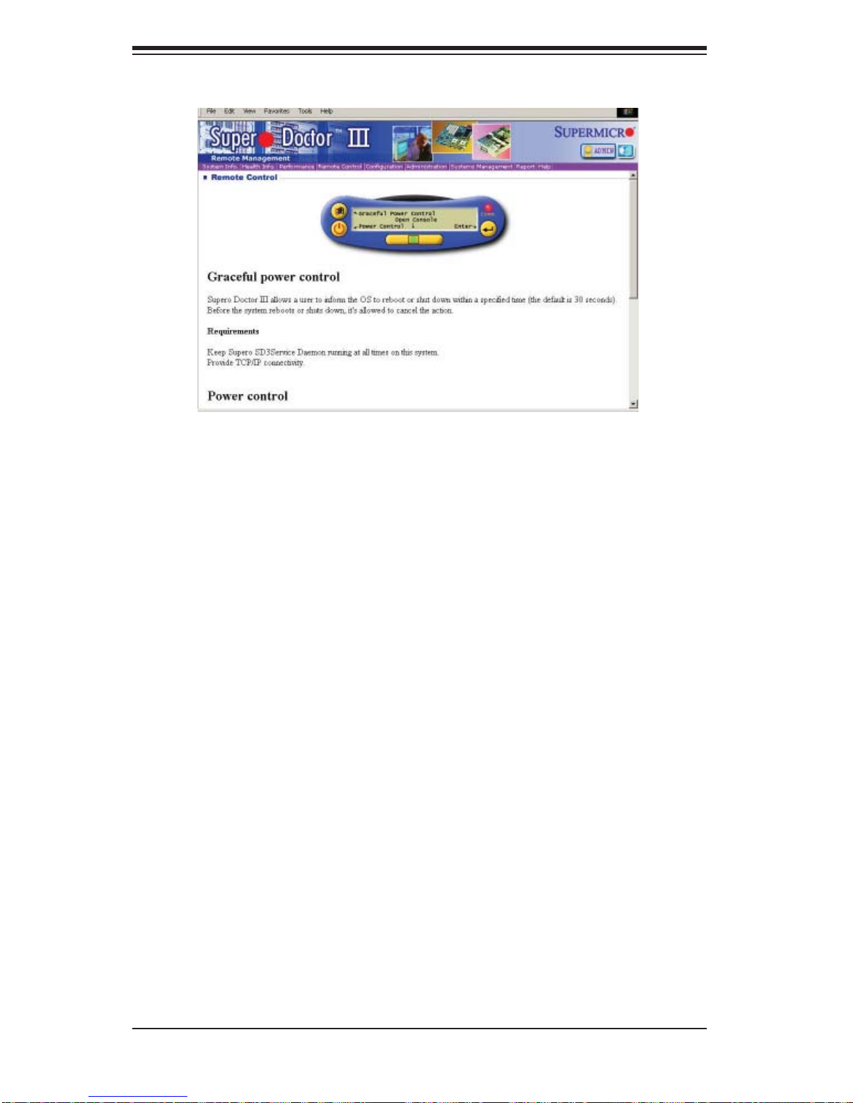
SuperWorkstation 7046A-6 User's Manual
Note: SD III Software Revision 1.0 can be downloaded from our Web site at: ftp://
ftp.supermicro.com/utility/Supero_Doctor_III/. You can also download SDIII User's
Guide at: http://www.supermicro.com/PRODUCT/Manuals/SDIII/UserGuide.pdf. For
Linux, we will still recommend that you use Supero Doctor II.
5-26
Page 59

Chapter 6: Advanced Chassis Setup
Chapter 6
Advanced Chassis Setup
This chapter covers the steps required to install components and perform simple
maintenance on the SC743TS-865BP-SQ chassis. Following the component installation steps in the order given will eliminate most common problems. If some
steps are unnecessary, skip ahead to the step that follows. Refer to Chapter 2 for
instructions on installing the system as a 4U rackmount.
Tools Required: The only tool you will need is a Philips screwdriver.
6-1 Static-Sensitive Devices
Static electrical discharge can damage electronic com ponents. To prevent damage
to any printed circuit boards (PCBs), it is important to handle them very carefully.
The following measures are generally suffi cient to protect your equipment from
static discharge.
Precautions
Use a grounded wrist strap designed to prevent static discharge.•
Touch a grounded metal object before removing any board from its antistatic •
bag.
Handle a board by its edges only; do not touch its components, peripheral chips,
•
memory modules or gold contacts.
When handling chips or modules, avoid touching their pins.•
Put the serverboard, add-on cards and peripherals back into their antistatic •
bags when not in use.
For grounding purposes, make sure your computer chassis provides excellent
•
conductivity between the power supply, the case, the mounting fasteners and
the serverboard.
Unpacking
The serverboard is shipped in antistatic packaging. When unpacking the board,
make sure the person handling it is static protected.
6-1
Page 60
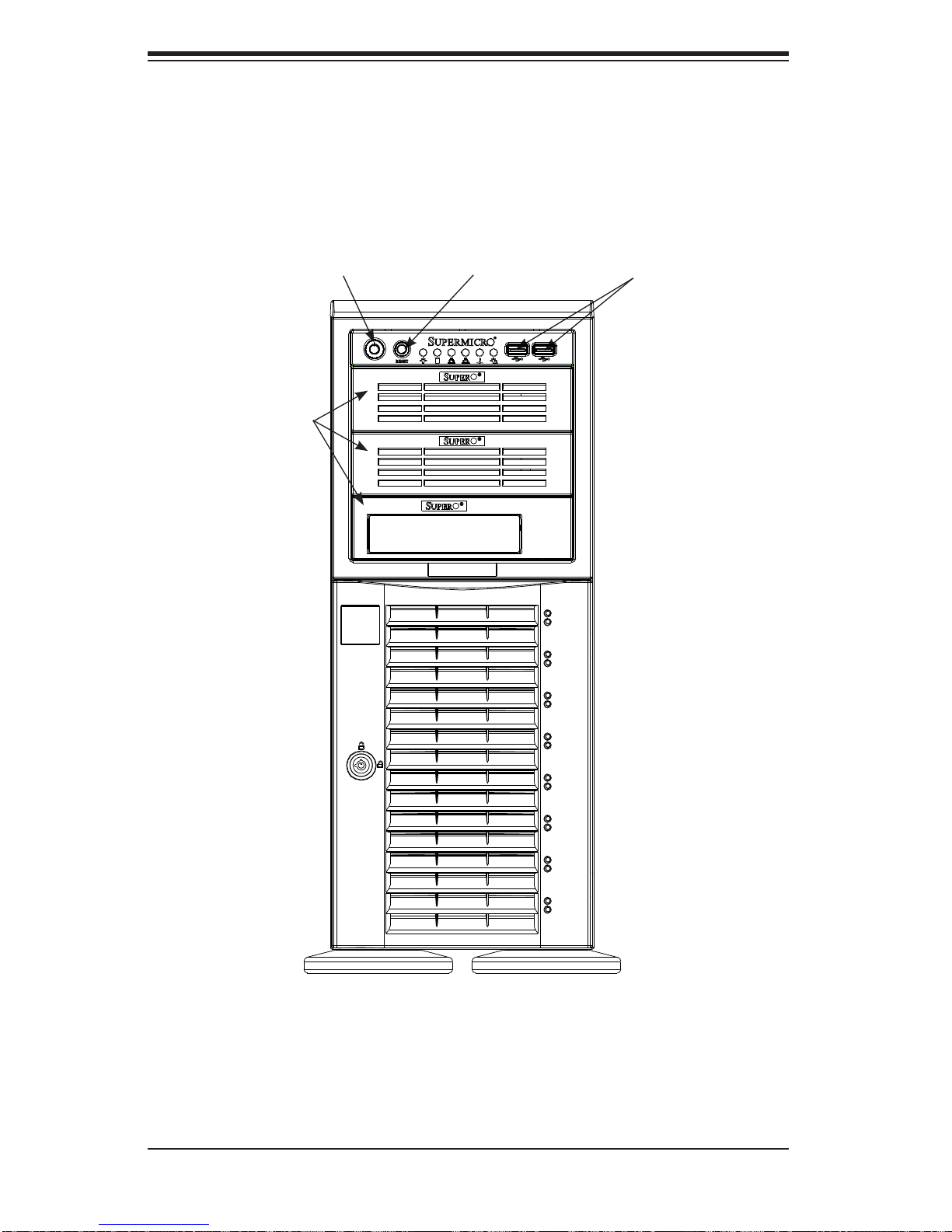
SuperWorkstation 7046A-6 User's Manual
Figure 6-1. Chassis Front View
5.25" Drive Bays (3)
System ResetMain Power
USB Ports
6-2
8 SAS Drive Bays
(behind locking bezel)
Page 61
Chapter 6: Advanced Chassis Setup
6-2 Front Control Panel
The front control panel must be connected to the JF1 connector on the serverboard
to provide you with system status and alarm indications. A ribbon cable has bundled
these wires together to simplify this connection.
Connect the cable from JF1 on the serverboard (making sure the red wire plugs
into pin 1) to the appropriate comnnector on the front control panel PCB (printed
circuit board). Pull all excess cabling over to the control panel side of the chassis.
The LEDs on the control panel inform you of system status - see Figure 6-2 for
details. See Chapter 5 for details on JF1.
Figure 6-2. Front Control Panel LEDs
Power
HDD
NIC1
NIC2
Overheat/Fan Fail
Power Fail
Indicates power is being supplied to the system.
Indicates IDE device and hard drive activity. On the
SC743TS-865BP-SQ, this LED indicates SAS/SATA hard
drive activity when fl ashing.
1
Indicates network activity on LAN port 1.
2
Indicates network activity on LAN port 2
When this LED fl ashes, it indicates a fan failure. When on
continuously it indicates an overheat condition (see Chapter
3 for details).
Indicates a power supply fan failure. An alarm will also
sound, which can be turned off with the reset switch on the
back of the power supply.
6-3
Page 62

SuperWorkstation 7046A-6 User's Manual
6-3 System Fans
Two 8-cm PWM chassis fans provide air intake while one 9-cm PWM exhaust fan
expels hot air from the chassis. All are low-noise fans that result in "Whisper-Quiet"
operation (~28 dB). The chassis is also fi tted with an air shroud to concentrate the
fl ow of cooling air through the system. The fans should be connected to headers
on the serverboard (see Chapter 5).
The power supply includes redundant cooling fans. If one fan fails, the rpm of the
remaining fan will ramp up its rpm to provide suffi cient cooling. The Power Fail LED
will illuminate and an audible alarm will sound, which can be silenced with a button on the power supply. If a power supply fan fails, you should replace the power
supply at your earliest convenience.
Fan Failure
Under normal operation, the chassis fans, the exhaust fan and the power supply
fans run continuously. The chassis fans are hot-pluggable and can be replaced
without powering down the system.
Replacing Chassis Cooling Fans
Removing a Fan
First locate the failed chassis fan by removing the top/left chassis cover (see 1.
Chapter 2 for details). Locate the fan that has stopped working.
Depress the locking tab on the failed fan: on a chassis fan, push the tab on 2.
the side of the housing inward, on the exhaust fan push down on the colored
tab.
With the tab depressed, pull the unit straight out (see Figure 6-3). The wiring 3.
for these fans has been designed to detach automatically.
Installing a New Fan
Replace the failed fan with an identical one (available from Supermicro)1.
Install it in the same position and orientation as the one you removed; it 2.
should click into place when fully inserted.
Check that the fan is working then replace the top/left side chassis panel.3.
6-4
Page 63
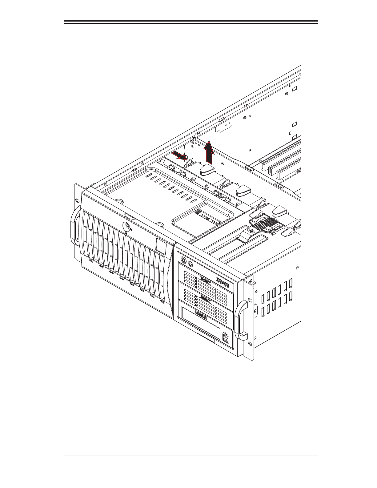
Chapter 6: Advanced Chassis Setup
Figure 6-3. Removing a Chassis Fan
6-5
Page 64
SuperWorkstation 7046A-6 User's Manual
!
6-4 Drive Bay Installation
A total of eight SAS (or six SATA) drives may be housed in the SC743TS-865BPSQ chassis. The drive IDs are preconfi gured as 0 through 7 (or 5) in order from
bottom to top (or from left to right if rackmounted). A bezel covers the drive area but
does not need to be removed to access the drives; simply swing open the bezel.
If you wish to remove the bezel piece, push on the three tabs on the inside of the
left lip of the front chassis cover. Then slightly swing out the same (left) side of the
cover - about ½ inch only. Remove by pushing on the open side of the cover to
remove it from the chassis (do not try to swing or pull it straight out after opening
the left side).
Regardless of how many SAS/SATA drives are installed, all drive
carriers must remain in the drive bays to promote proper airfl ow.
Installing/Removing SAS/SATA Drives
The SAS/SATA drive carriers are all easily accessible at the front of the chassis.
These drives are hot-swappable, meaning they can be removed and installed without powering down the system.
Open the front bezel then push the release button located beside the drive 1.
LEDs.
Swing the handle fully out and then use it to pull the unit straight out.2.
Note: Your operating system must have RAID support to enable the hot-swap
capability of the SAS/SATA drives.
Mounting a SAS/SATA drive in a Drive Carrier
The SAS/SATA drive carriers help to promote proper airfl ow for the system. For this
reason, even carriers without SAS/SATA drives must remain in the chassis.
Insert the drive into the carrier with the printed circuit board side facing down 1.
so that the mounting holes align with those in the carrier.
Secure the drive to the carrier with four screws (see Figure 6-5).2.
6-6
Page 65
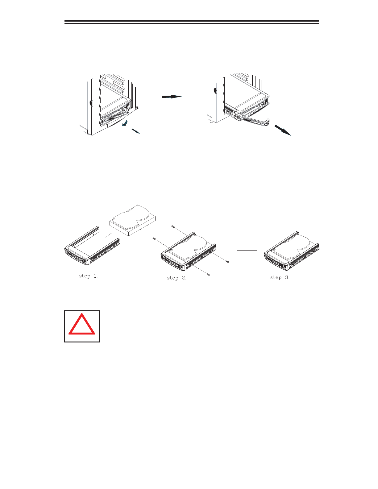
Chapter 6: Advanced Chassis Setup
!
Figure 6-4. Removing a SAS/SATA Drive Carrier
Figure 6-5. Mounting a SAS/SATA Drive in a Carrier
Important! Use extreme caution when working around the SAS/
SATA backplane. Do not touch the backplane with any metal
objects and make sure no ribbon cables touch the backplane or
obstruct the airfl ow holes.
SAS/SATA Backplane
The SAS/SATA drives plug into a SAS/SATA backplane. A data cable (CBL-061L)
for each drive and two SAS/SATA LED cables (CBL-0157L) need to be connected
from the serverboard to the appropriate connectors on the backplane. You cannot
cascade the SAS/SATA backplane.
6-7
Page 66

SuperWorkstation 7046A-6 User's Manual
Installing Components in the 5.25" Drive Bays
The 7046A-6 has three 5.25" drive bays. Components such as SATA hard drives or
DVD/CD-ROM drives can be installed into these 5.25" drive bays.
Removing the Empty Drive Bay
First power down the system.1.
Remove the top/left chassis cover to access the drive components.2.
With the cover off, remove the screws that secure the drive carrier to the 3.
chassis (one side only) then push the entire empty drive carrier out from the
back.
Adding a DVD/CD-ROM Drive
Remove the guide plates (one on each side) from the empty drive carrier 1.
and screw them into both sides of the DVD/CD-ROM drive using the holes
provided.
Slide the DVD/CD-ROM into the bay and secure it to the chassis with the 2.
drive carrier screws you fi rst removed.
Attach the power and data cables to the drive.3.
Replace the top/left chassis cover and restore power to the system.4.
Adding a SATA Drive
Install an SATA drive into one of the removed empty drive carriers.1.
Secure the drive to the carrier with screws then slide the assembly into 2.
the bay and secure it to the chassis with the drive carrier screws you fi rst
removed.
Attach the power and data cables to the drive.3.
Replace the top/left chassis cover and restore power to the system.4.
Note: Drive carriers should remain in any empty drive bays to maintain proper
airfl ow within the chassis.
6-8
Page 67

Chapter 6: Advanced Chassis Setup
6-5 Power Supply
The SuperWorkstation 7046A-6 has a single 865 watt power supply. This power
unit is equipped with low-noise technology, making the system ideal for workstation
environments.
The power supply has an auto-switching capability that enable it to automatically
sense and operate with 100 or 240 volt inputs.
Power Supply Failure
If the power supply unit fails, the system will shut down and you will need to replace
the power supply unit. Replace with the same model - PWS-865-PQ, which can be
ordered directly from Supermicro (see Contact Information in the Preface). As there
is only one power supply unit, the system must be powered down before removing
and/or replacing the power supply for whatever reason.
Replacing the Power Supply
First power down the system.1.
Unplug the power cord from the power supply module.2.
Remove the screws that secure the module to the chassis then pull it com-3.
pletely out.
Replace the failed unit with another unit of the exact same part number 4.
(PWS-865-PQ).
Gently but fi rmly push the new unit all the way into the open bay.5.
Secure it to the chassis using the screws you previously removed.6.
Finish by replacing the chassis left/top cover and then plugging the power 7.
cord back into the new module you just added.
Push the power button to restart the system.8.
6-9
Page 68

SuperWorkstation 7046A-6 User's Manual
Notes
6-10
Page 69

Chapter 7: BIOS
Chapter 7
BIOS
7-1 Introduction
This chapter describes the AMI BIOS Setup Utility for the X8DA6. The AMI ROM
BIOS is stored in a Flash EEPROM and can be easily updated. This chapter describes the basic navigation of the AMI BIOS Setup Utility setup screens.
Note: For instructions on BIOS recovery, please refer to the instruction
guide posted at http://www.supermicro.com/support/manuals/.
Starting BIOS Setup Utility
To enter the AMI BIOS Setup Utility screens, press the <Delete> key while the
system is booting up.
Note: In most cases, the <Delete> key is used to invoke the AMI BIOS
setup screen. There are a few cases when other keys are used, such as
<F1>, <F2>, etc.
Each main BIOS menu option is described in this manual. The Main BIOS setup
menu screen has two main frames. The left frame displays all the options that can
be confi gured. Grayed-out options cannot be confi gured. Options in blue can be
confi gured by the user. The right frame displays the key legend. Above the key
legend is an area reserved for a text message. When an option is selected in the
left frame, it is highlighted in white. Often a text message will accompany it. (Note:
The AMI BIOS has default text messages built in. Supermicro retains the option to
include, omit, or change any of these text messages.)
The AMI BIOS Setup Utility uses a key-based navigation system called "hot keys."
Most of the AMI BIOS setup utility "hot keys" can be used at any time during the
setup navigation process. These keys include <F1>, <F10>, <Enter>, <ESC>, arrow keys, etc.
Note: Options printed in Bold are default settings.
How To Change the Confi guration Data
The confi guration data that determine the system parameters may be changed by
entering the AMI BIOS Setup utility. This Setup utility can be accessed by pressing
<Del> at the appropriate time during system boot.
7-1
Page 70
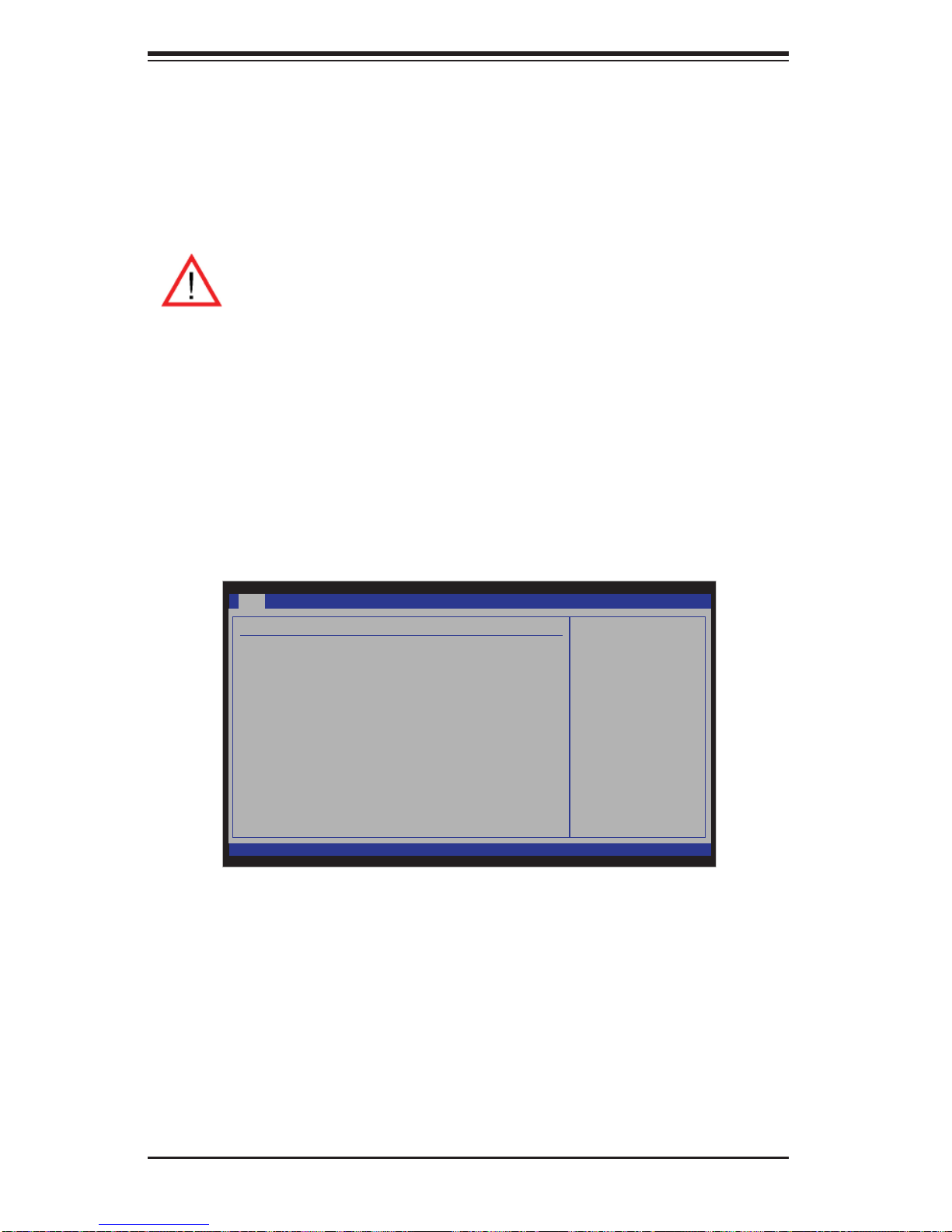
SuperWorkstation 7046A-6 User's Manual
Starting the Setup Utility
Normally, the only visible Power-On Self-Test (POST) routine is the memory test.
As the memory is being tested, press the <Delete> key to enter the main menu of
the AMI BIOS Setup Utility. From the main menu, you can access the other setup
screens. An AMI BIOS identifi cation string is displayed at the bottom left corner of
the screen below the copyright message.
Warning! Do not upgrade the BIOS unless your system has a BIOS-related
issue. Flashing the wrong BIOS can cause irreparable damage to the
system. In no event shall Supermicro be liable for direct, indirect, special,
incidental, or consequential damages arising from a BIOS update. If you
need to update the BIOS, do not shut down or reset the system while the
BIOS is updating to avoid possible boot failure.
7-2 Main Setup
When you fi rst enter the AMI BIOS Setup Utility, you will enter the Main setup screen.
You can always return to the Main setup screen by selecting the Main tab at the
top of the screen. The Main BIOS Setup screen is shown below.
Main Advanced
System Overview
System Time [09:20:40]
System Date [Wed 08/012/2009]
Supermicro X8DA6/X8DAE
BIOS Build Ver : 0.60
BIOS Build Date : 08/11/09
AMIBIOS Core Ver : 08.00.15
Processor
Intel(R) Xeon (R) CPU X5550 @ 2.67GHz
Speed : 2666MHz
Physical Count : 1
Logical Count : 8
Microcode Rev : 9
System Memory
Size : 4088MB
Security
vXX.XX (C) Copyright 1985-2009, American Megatrends, Inc.
BIOS SETUP UTILITY
Boot
Exit
Use [ENTER], [TAB]
or [SHIFT-TAB] to
select a eld.
Use [+] or [-] to
congure system time.
Select Screen
Select Item
+- Change Field
Tab Select Field
F1 General Help
F10 Save and Exit
ESC Exit
System Overview: The following BIOS information will be displayed:
System Time/System Date
Use this option to change the system time and date. Highlight System Time or System Date using the arrow keys. Key in new values through the keyboard and press
<Enter>. Press the <Tab> key to move between fi elds. The date must be entered
in MM/DD/YY format. The time is entered in HH:MM:SS format. (Note: The time is
in the 24-hour format. For example, 5:30 P.M. appears as 17:30:00.)
7-2
Page 71

Chapter 7: BIOS
Supermicro X8DA6
BIOS Build Version: This item displays the BIOS revision used in your sys-
•
tem.
BIOS Build Date: This item displays the date when this BIOS was built.
•
AMI BIOS Core Version: This item displays the revision number of the AMI BIOS •
Core upon which your BIOS was built.
Processor
The AMI BIOS will automatically display the status of the processor used in your
system:
CPU Type: This item displays the type of CPU used in the motherboard.
•
Speed: This item displays the speed of the CPU detected by the BIOS.•
Physical Count: This item displays the number of processors installed in your •
system as detected by the BIOS.
Logical Count: This item displays the number of CPU Cores installed in your
•
system as detected by the BIOS.
Micro_code Revision: This item displays the revision number of the BIOS Mi-
•
cro_code used in your system.
System Memory
This displays the size of memory available in the system:
Size: This item displays the memory size detected by the BIOS.
•
7-3
Page 72
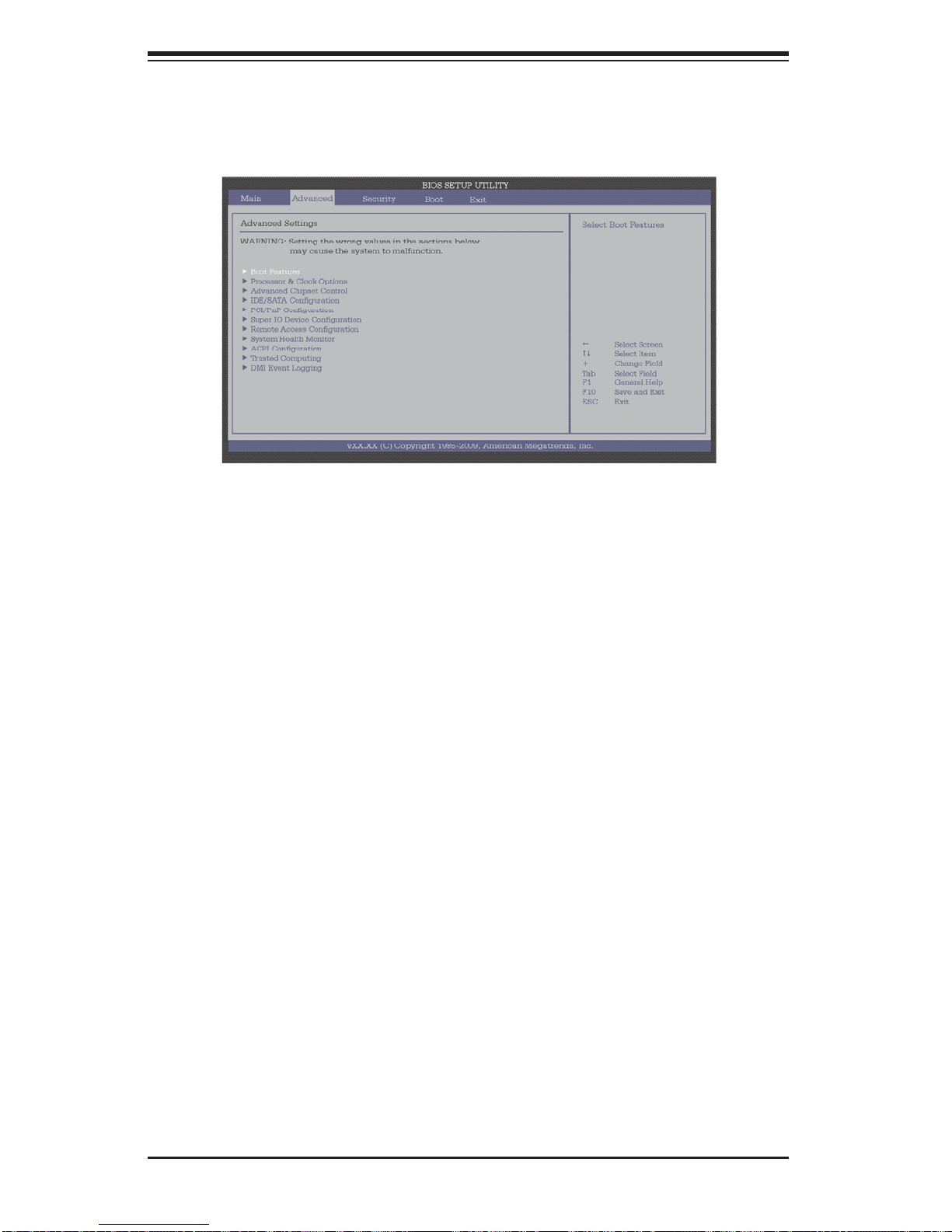
SuperWorkstation 7046A-6 User's Manual
7-3 Advanced Setup Confi gurations
Use the arrow keys to select Boot Setup and hit <Enter> to access the submenu
items.
XBoot Features
Quick Boot
If enabled, this option will skip certain tests during POST to reduce the time needed
for system boot. The options are Enabled and Disabled.
Quiet Boot
This option allows the bootup screen options to be modifi ed between POST mes-
sages or the OEM logo. Select Disabled to display the POST messages. Select
Enabled to display the OEM logo instead of the normal POST messages. The options are Enabled and Disabled.
AddOn ROM Display Mode
This sets the display mode for the Option ROM. Select Keep Current to use the current AddOn ROM Display setting. Select Force BIOS to use the Option ROM display
mode set by the system BIOS. The options are Force BIOS and Keep Current.
Bootup Num-Lock
This featu re select s the power-on st ate for the <N umlock> key. The optio ns are
Of f and On.
Wait For 'F1' If Error
This for ce s the sys tem to wai t until t he ' F1' key is pressed i f an er ror o cc urs . The
option s are Dis able d, and Enabled.
Hit 'Del' Message Display
This feature displays "Press DEL to run Setup" during POST. The options are
Enabled, and Disabled.
7-4
Page 73

Chapter 7: BIOS
Interrupt 19 Capture
Interrupt 19 is the software interrupt that handles the boot disk function. When this
item is set to Enabled, the ROM BIOS of the host adaptors will "capture" Interrupt
19 at boot and allow the drives that are attached to these host adaptors to function
as bootable disks. If this item is set to Disabled, the ROM BIOS of the host adaptors will not capture Interrupt 19, and the drives attached to these adaptors will not
function as bootable devices. The options are Enabled, and Disabled.
Power Confi guration
Power Button Function
If this item is set to Instant_Off, the system will power off immediately as soon as
the user hits the power button. If set to 4_Second_Override, the system will power
off when the user presses the power button for 4 seconds or longer. The options
are Instant_Off and 4_Second_Override.
Restore on AC Power Loss
Use this feature to set the power state after a power outage.
Select Power-Off for the system power to remain off after a power loss.
•
Select Power-On for the system power to be turned on after a power loss. •
Select Last State to allow the system to resume its last state before a power •
loss.
The options are Power-On, Power-Off and Last State.
Watch Dog Function
If enable d, the Watch Dog T i mer will allo w the system to reboot when it is in active
for more t han 5 minu tes. The o ption s are Enabl ed and Disabled.
XProcessor and Clock Options
This submenu allows the user to confi gure the Processor and Clock settings.
Ratio CMOS Setting
This feature allows the user to set the ratio between CPU Core Clocks and the
FSB Frequency. Select Auto to allow the BIOS to automatically confi gure the CPU
Ratio. The default setting is 14.
7-5
Page 74

SuperWorkstation 7046A-6 User's Manual
C1E Support
Select Enabled to use the feature of Enhanced Halt State. C1E signifi cantly reduces
the CPU's power consumption by reducing the CPU's clock cycle and voltage during
a "Halt State." The options are Disabled and Enabled.
Hardware Prefetcher (Available when supported by the CPU)
If this item is set to Enabled, the hardware prefetcher will prefetch streams of data
and instructions from the main memory to the L2 cache in the forward or backward
manner to improve CPU performance. The options are Disabled, and Enabled.
Adjacent Cache Line Prefetch (Available when supported by the CPU)
The CPU fetches the cache line for 64 bytes if this option is set to Disabled. The CPU
fetches both cache lines for 128 bytes as comprised if the item is set to Enabled.
MPS and ACPI MADT Ordering
This featur e all ows t he us er to c on fi gure the MP S (M ult i - Pr oc e ss or S pe ci fi cation)
and ACPI settings for your motherboard. Select Modern Ordering if the XP or a
newer version of Windows OS is used in the motherboard. Select Legacy Ordering
if the 2000 or a n e arlier ver s io n o f W in d ows O S i s us e d. T he o pt i o ns a re Modern
Ordering and Legacy Ordering.
Max CPUID Value Limit
This feature allows the user to set the maximum CPU ID value. Enable this function
to boot the legacy operating systems that cannot support processors with extended
CPUID functions. The options are Enabled and Disabled (for the Windows OS.).
Intel® Virtualization Technology (Available when supported by the CPU)
Select Enabled to use the feature of Virtualization T echnology to allow one platform
to run multiple operating systems and applications in independent partitions, creating mult iple " vi r tu al" sy stems i n one p hysic al c o mput er. The opti ons ar e Enabled
and Dis abled. Not e: If there is any change to this setting, you will need to power
off an d restart the system for the cha nge to take ef f ect. Plea se refer to Intel ’s web
site for detailed information.
Execute-Disable Bit Capability (Available when supported by the OS and
the CPU)
Select Enabled to enable the Execute Disable Bit which will allow the processor
to designate areas in the system memory where an application code can execute
and where it cannot, thus preventing a worm or a virus from fl ooding illegal codes
to overwhelm the processor or damage the system during an attack. The default is
Enabled. (Refer to Intel and Microsoft Web Sites for more information.)
7-6
Page 75

Chapter 7: BIOS
Simultaneous Multi-Threading (Available when supported by the CPU)
Set to Enabled to use the Simultaneous Multi-Threading Technology, which will
result in increased CPU performance. The options are Disabled and Enabled.
Active Processor Cores
Set to Enabled to use a processor's Second Core and beyond. (Please refer to
Intel's web site for more information.) The options are All, 1 and 2.
Intel® SpeedStep™ Technology
EIST (Enhanced Intel SpeedStep Technology) allows the system to automatically
adjust processor voltage and core frequency in an effort to reduce power consumption and heat dissipation. Please refer to Intel’s web site for detailed information.
The options are Disable (Disable GV3) and Enable (Enable GV3).
Intel® C-STATE Tech
When this item is enabled, C-State is set by the system automatically to either C2,
C3 or C4 state. The options are Enabled and Disabled.
C-State Package Limit Setting
When this item is set to Auto, the AMI BIOS will automatically set the limit on the
C-State package register. The options are Auto, C1, C3, C6 and C7.
C1 Auto Demotion
When this item is enabled, the CPU will conditionally demote C3, C6 or C7 requests
to C1 based on un-core auto-demote information. The options are Disabled and
Enabled.
C3 Auto Demotion
When this item is enabled, the CPU will conditionally demote C6 or C7 requests
to C3 based on un-core auto-demote information. The options are Disabled and
Enabled.
Clock Spread Spectrum
Select Enable to use the feature of Clock Spectrum, which will allow the BIOS to
monitor and attempt to reduce the level of Electromagnetic Interference caused by
the components whenever needed. The options are Disabled and Enabled.
7-7
Page 76

SuperWorkstation 7046A-6 User's Manual
XAdvanced Chipset Control
The items included in the Advanced Settings submenu are listed below:
XCPU Bridge Confi guration
QPI Links Speed
This feature selects QPI's data transfer speed. The options are Slow-mode, and
Full Speed.
QPI Frequency
This selects the desired QPI frequency. The options are Auto, 4.800 GT,
5.866GT, and 6.400 GT.
QPI L0s and L1
This enables the QPI power state to low power. L0s and L1 are automatically
selected by the motherboard. The options are Disabled and Enabled.
Memory Frequency
This feature forces a DDR3 frequency to run at a speed specifi ed by the user.
The available options are Auto, Force DDR-800, Force DDR-1066, Force DDR1333 and Force SPD.
Memory Mode
The options are Independent, Channel Mirroring, and Lockstep.
Independent - All DIMMs are available to the operating system.
Channel Mirroring - The motherboard maintains two identical copies of all data
in memory for data security.
Lockstep - The motherboard uses two areas of memory to run the same set of
operations in parallel.
Demand Scrubbing
This is a memory error-correction scheme in which the Processor writes corrected data back into the memory block from where it was read by the Processor.
The options are Enabled and Disabled.
Patrol Scrubbing
This is a memory error-correction scheme that works in the background looking
for and correcting resident errors. The options are Enabled and Disabled.
Throttling - Closed Loop/Throttling - Open Loop
Throttling improves reliability and reduces power consumption by automatic voltage control during CPU idle states. The options are Disabled and Enabled.
7-8
Page 77

Chapter 7: BIOS
If the item above is enabled, the following items will display.
Hysteresis Temperature (Closed Loop Only)
Temperature Hysteresis is the temperature lag (in degrees Celsius) after
the predefi ned DIMM temperature threshold is reached before Closed Loop
Throttling begins. The options are Disabled, 1.5
o
C, 3.0oC, and 6.0oC.
Guardband Temperature (Closed Loop Only)
This is the temperature which applies to the DIMM temperature threshold.
Each step is in 0.5
o
C increment. The default is [006]. Press <+> or <-> on
your keyboard to change this value.
Inlet Temperature
This is the temperature detected at the chassis inlet. Each step is in 0.5
o
C
increments. The default is [070]. Press <+> or <-> to change this value.
Temperature Rise
This is the temperature rise to the DIMM thermal zone. Each step is in 0.5
o
C
increments. The default is [020]. Press <+> or <-> to change this value.
Air Flow
This is the air fl ow speed to the DIMM modules. Each step is one mm/sec.
The default is [1500]. Press <+> or <-> to change this value.
Altitude
This feature defi nes how many meters above or below sea level the system
is located. The options are Sea Level or Below, 1~300, 301~600, 601~900,
901~1200, 1201~1500, 1501~1800, 1801~2100, 2101~2400, 2401~2700,
2701~3000. Press <+> or <-> to change this value.
DIMM Pitch
This is the physical space between each DIMM module. Each step is in
1/1000 of an inch. The default is [400]. Press <+> or <-> to change this
value.
XNorth Bridge Confi guration
This feature allows the user to confi gure Intel IOH settings.
Crystal Beach/DMA (Direct Memory Access)
This feature works in conjunction with the Intel I/O AT (Acceleration Technology)
to accelerate the performance of a TOE device, which is a specialized, dedicated
processor installed on an add-on card or a network card to handle some or all
packet processing of this add-on card.) When this feature is set to Enabled, it will
7-9
Page 78

SuperWorkstation 7046A-6 User's Manual
enhance overall system performance by providing direct memory access for data
transferring. The options are Enabled and Disabled.
Crystal Beach/DCA (Available when Crystal Beach/DMA is enabled.)
This feature works in conjunction with the Intel I/O AT (Acceleration Technology) to
accelerate the performance of the TOE device. When this feature set to Enabled, it
will enhance overall system performance by providing direct cache access for data
transferring. The options are Enabled and Disabled.
Payload Size
Some add-on cards perform faster when the payload size is limited to 128 Bytes;
while others, with a payload size of 256 Bytes. Please refer to your add-on card
user guide for the desired setting. The options are 256 Bytes and 128 Bytes.
Intel VT-d
Select Enabled to enable Intel's Virtualization Technology support for Direct I/O VT-d
by reporting the I/O device assignments to VMM through the DMAR ACPI Tables.
This feature offers fully-protected I/O resource-sharing across the Intel platforms,
providing the user with greater reliability, security and availability in networking and
data-sharing. The settings are Enabled and Disabled.
XSouthBridge Confi guration
This feature allows the user to confi gure Intel ICH South Bridge settings.
USB Functions
This feature allows the user to enable or disable onboard USB support. The Options
are: Disabled, and Enabled.
Legacy USB Support
Select Enabled to use Legacy USB devices. If this item is set to Auto, Legacy USB
support will be automatically enabled if a legacy USB device is installed on the
motherboard, and vise versa. The settings are Disabled, and Enabled.
USB 2.0 Controller Mode
This setting allows you to select the USB 2.0 Controller mode. The options are
Hi-Speed (480 Mbps) and Full Speed (12 Mbps).
BIOS EHCI Hand-Off
Select Enabled to enable BIOS Enhanced Host Controller Interface support to
provide a workaround solution for an operating system that does not have EHCI
Hand-Off support. When enabled, the EHCI Interface will be changed from the BIOScontrolled to the OS-controlled. The options are Disabled and Enabled.
7-10
Page 79

Chapter 7: BIOS
HDA Controller
Select Enabled to activate the onboard High-Defi nition Audio controller. The options
are Enabled and Disabled.
Front_Side Audio Mode
Use this feature to select Front Side Audio Mode. Select HD Audio to enable HD
(High-Defi nition) Audio support. Select AC' 97 to use AC' 97 Audio. The options are
HD Audio and AC' 97 Audio.
XIntel PCI-X Hub Confi guration
A0 Bus Frequency/B0 Bus Frequency
This feature allows the user to set the frequency for the PCI-X Bus A0 or Bus B0.
The Options are Auto, 33 MHz PCI, 66 MHz PCI, 66 MHz PCI-XM1, 100 MHz
PCI-XM1, and 133 MHz PCI-XM1.
I/O Port Decode
This feature allows the user to select the decode range for the onboard IO connections. The settings are 4K Decode, and 1K Decode.
RAS Sticky Error Handling
This feature allows the user to specify how sticky RAS errors to be handled. The
settings are Clear Errors, and Leave Errors.
VGA 16-Bit Decode
Select Enabled to enable 16-Bit decode support for VGA devices behind the PXH
connection. The settings are Enabled, and Disabled.
XIDE/SATA Confi guration
When this submenu is selected, the AMI BIOS automatically detects the presence
of the IDE devices and displays the following items:
SATA#1 Confi guration
If Compatible is selected, it sets SATA#1 to legacy compatibility mode, while selecting Enhanced sets SATA#1 to native SATA mode. The options are Disabled,
Compatible and Enhanced.
Confi gure SATA#1 as
This feature allows the user to select the drive type for SATA#1. The options are
IDE, RAID Intel, RAID Adaptec, and AHCI.
7-11
Page 80

SuperWorkstation 7046A-6 User's Manual
SATA#2 Confi guration
Selecting Enhanced will set SA T A#2 to native SA TA mode. The options are Disabled,
and Enhanced.
Primary IDE Master/Slave, Secondary IDE Master/Slave, Third IDE Master,
and Fourth IDE Master
These settings allow the user to set the parameters of the IDE drives specifi ed.
Hit <Enter> to activate the following submenu screen for detailed options of these
items. Set the correct confi gurations accordingly.
Type
This feature allows the user to specify the type of device connected to the system.
Select Auto to allow the BIOS to automatically select the IDE type for the drive
as detected. Select ARMD for removable devices. The options are Not Installed,
Auto, CD/DVD and ARMD.
LBA/Large Mode
LBA (Logical Block Addressing) is a method of addressing data on a disk drive.
In the LBA mode, the maximum drive capacity is 137 GB. For drive capacities
over 137 GB, your system must be equipped with a 48-bit LBA mode addressing.
If not, contact your manufacturer or install an ATA/133 IDE controller card that
supports 48-bit LBA mode. The options are Disabled and Auto.
Block (Multi-Sector Transfer)
Block Mode boosts the IDE drive performance by increasing the amount of data
transferred. Only 512 bytes of data can be transferred per interrupt if Block Mode
is not used. Block Mode allows transfers of up to 64 KB per interrupt. Select
Disabled to allow data to be transferred from and to the device one sector at
a time. Select Auto to allow data transfer from and to the device occur multiple
sectors at a time if the device supports it. The options are Auto and Disabled.
PIO Mode
The IDE PIO (Programmable I/O) Mode programs timing cycles between the
IDE drive and the programmable IDE controller. As the PIO mode increases, the
cycle time decreases. The options are Auto, 0, 1, 2, 3, and 4.
Select Auto to allow the AMI BIOS to automatically detect the PIO mode. Use
this value if the IDE disk drive support cannot be determined.
Select 0 to allow the AMI BIOS to use PIO mode 0. It has a data transfer rate
of 3.3 MB/s.
Select 1 to allow the AMI BIOS to use PIO mode 1. It has a data transfer rate
of 5.2 MB/s.
7-12
Page 81

Chapter 7: BIOS
Select 2 to allow the AMI BIOS to use PIO mode 2. It has a data transfer rate
of 8.3 MB/s.
Select 3 to allow the AMI BIOS to use PIO mode 3. It has a data transfer rate
of 11.1 MB/s.
Select 4 to allow the AMI BIOS to use PIO mode 4. It has a data transfer bandwidth of 32-Bits. Select Enabled to enable 32-Bit data transfer.
DMA Mode
Select Auto to allow the BIOS to automatically detect IDE DMA mode when the
IDE disk drive support cannot be determined.
Select SWDMA0 to allow the BIOS to use Single Word DMA mode 0. It has a
data transfer rate of 2.1 MB/s.
Select SWDMA1 to allow the BIOS to use Single Word DMA mode 1. It has a
data transfer rate of 4.2 MB/s.
Select SWDMA2 to allow the BIOS to use Single Word DMA mode 2. It has a
data transfer rate of 8.3 MB/s.
Select MWDMA0 to allow the BIOS to use Multi Word DMA mode 0. It has a
data transfer rate of 4.2 MB/s.
Select MWDMA1 to allow the BIOS to use Multi Word DMA mode 1. It has a
data transfer rate of 13.3 MB/s.
Select MWDMA2 to allow the BIOS to use Multi-Word DMA mode 2. It has a
data transfer rate of 16.6 MB/s.
Select UDMA0 to allow the BIOS to use Ultra DMA mode 0. It has a data transfer
rate of 16.6 MB/s. It has the same transfer rate as PIO mode 4 and Multi Word
DMA mode 2.
Select UDMA1 to allow the BIOS to use Ultra DMA mode 1. It has a data transfer
rate of 25 MB/s.
Select UDMA2 to allow the BIOS to use Ultra DMA mode 2. It has a data transfer
rate of 33.3 MB/s.
Select UDMA3 to allow the BIOS to use Ultra DMA mode 3. It has a data transfer
rate of 66.6 MB/s.
Select UDMA4 to allow the BIOS to use Ultra DMA mode 4. It has a data transfer
rate of 100 MB/s.
Select UDMA5 to allow the BIOS to use Ultra DMA mode 5. It has a data transfer
rate of 133 MB/s.
Select UDMA6 to allow the BIOS to use Ultra DMA mode 6. It has a data transfer
rate of 133 MB/s. The options are Auto, SWDMAn, MWDMAn, and UDMAn.
7-13
Page 82

SuperWorkstation 7046A-6 User's Manual
S.M.A.R.T. For Hard disk drives
Self-Monitoring Analysis and Reporting Technology (SMART) can help predict
impending drive failures. Select Auto to allow the AMI BIOS to automatically detect hard disk drive support. Select Disabled to prevent the AMI BIOS from using
the S.M.A.R.T. Select Enabled to allow the AMI BIOS to use the S.M.A.R.T. to
support hard drive disk. The options are Disabled, Enabled, and Auto.
32Bit Data Transfer
Select Enable to enable the function of 32-bit IDE data transfer. The options are
Enabled and Disabled.
IDE Detect Timeout (sec)
Use this feature to set the time-out value for the BIOS to detect the IDE devices
installed in the system. The options are 0 (sec), 5, 10, 15, 20, 25, 30, and 35.
XPCI/PnP Confi guration
Clear NVRAM
This feature clears the NVRAM during system boot. The options are No and Yes.
Plug & Play OS
Selecting Yes allows the OS to confi gure Plug & Play devices. (This is not required
for system boot if your system has an OS that supports Plug & Play.) Select No to
allow the AMI BIOS to confi gure all devices in the system.
PCI Latency Timer
This feature sets the latency Timer of each PCI device installed on a PCI bus. Select
64 to set the PCI latency to 64 PCI clock cycles. The options are 32, 64, 96, 128,
160, 192, 224 and 248.
PCI IDE Bus Master
When enabled, the BIOS uses PCI bus mastering for reading/writing to IDE drives.
The options are Disabled and Enabled.
Slot 1 Option ROM~Slot 6 Option ROM
Select Enabled to enable Slot 1 Option ROM~Slot 6 Option ROM, which will allow
you to boot the computer from a PCI device installed on a PCI slot. The options
are Disabled and Enabled.
LAN1 PXE/LAN2 PXE PXE Option ROM
Select Enabled to enable the onboard LAN1/LAN2 PXE Option ROMs. This is
to boot computers using a network interface. The options are Enabled and Dis-
abled.
7-14
Page 83

Chapter 7: BIOS
LSI SAS2 2008 Option ROM
Select Enabled to enable the LSI SAS2 2008 Option ROM. This is to boot computers using a network interface. The options are Enabled and Disabled.
XSuper IO Device Confi guration
Onboard Floppy Controller
Select Enable to enable the onboard Floppy Controller. The options are Enabled
and Disabled.
Floppy A/Floppy B
This feature allows the user to select the type of fl oppy drive connected to the sys-
tem as specifi ed. The options are Disabled, 360KB 5 1/4", 1.2MB 5 1/4", 720KB 3
1/2", 1.44MB 3 1/2" and 2.88MB 3 1/2". The default setting for Floppy A is 1.44MB
3 1/2", and for Floppy B is Disabled.
Serial Port1 Address/ Serial Port2 Address
This option specifi es the base I/O port address and the Interrupt Request address
of Serial Port 1 and Serial Port 2. Select Disabled to prevent the serial port from
accessing any system resources. When this option is set to Disabled, the serial port
physically becomes unavailable. Select 3F8/IRQ4 to allow the serial port to use 3F8
as its I/O port address and IRQ 4 for the interrupt address. The options for Serial
Port1 are Disabled, 3F8/IRQ4, 3E8/IRQ4, 2E8/IRQ3. The options for Serial Port2
are Disabled, 2F8/IRQ3, 3E8/IRQ4, and 2E8/IRQ3.
Serial Port 2 Mode
Use this feature to confi gure Serial Port 2 mode. The options are Normal, IrDA
and ASK IR. IrDA (Infrared Data) is an industry standard for remote control devices. ASK IR (Amplitude Shifted Keying Infrared) is a protocol compatible with
Sharp® branded PDAs and other infrared devices.
XRemote Access Confi guration
Remote Access
This allows the user to enable the Remote Access feature. The options are Dis-
abled and Enabled.
If Remote Access is set to Enabled, the following items will display:
Serial Port Number
This feature allows the user decide which serial port to be used for Console
Redirection. The options are COM 1 and COM 2.
7-15
Page 84

SuperWorkstation 7046A-6 User's Manual
Serial Port Mode
This feature allows the user to set the serial port mode for Console Redirection.
The options are 115200 8, n 1; 57600 8, n, 1; 38400 8, n, 1; 19200 8, n, 1; and
9600 8, n, 1.
Flow Control
This feature allows the user to set the fl ow control for Console Redirection. The
options are None, Hardware, and Software.
Redirection After BIOS POST
Select Disabled to turn off Console Redirection after Power-On Self-Test
(POST). Select A lways to keep Console Redirecti on active all the time after
POST. (Note: This set ti ng may not b e supp or ted by so me op erat ing syst ems.)
Select Boot Loader to keep Console Redirection active during POST and Boot
Loader. The opti ons are D isabl ed, Boot L oader, and Always.
Terminal Type
This feature allows the user to select the target terminal type for Console Redirection. The options are ANSI, VT100, and VT-UTF8.
VT-UTF8 Combo Key Support
A terminal keyboard defi nition that provides a way to send commands from a
remote console. Available options are Enabled and Disabled.
Sredir Memory Display Delay
This feature defi nes the length of time in seconds to display memory information.
The options are No Delay, Delay 1 Sec, Delay 2 Sec, and Delay 4 Sec.
XSystem Health Monitor
This feature allows the user to monitor system health and review the status of each
item as displayed.
CPU Overheat Alarm
This option allows the user to select the CPU Overheat Alarm setting which determines when the CPU OH alarm will be activated to provide warning of possible
CPU overheat.
Warning!
1. Any temperature that exceeds the CPU threshold temperature pre-
defi ned by the CPU manufacturer may result in CPU overheat or system
instability. When the CPU temperature reaches this predefi ned threshold,
the CPU and system cooling fans will run at full speed.
7-16
Page 85

Chapter 7: BIOS
2. To avoid possible system overheating, please be sure to provide adequate airfl ow to your system.
The options are:
The Early Alarm: Select this setting if you want the CPU overheat alarm (includ-
•
ing the LED and the buzzer) to be triggered as soon as the CPU temperature
reaches the CPU overheat threshold as predefi ned by the CPU manufacturer.
The Default Alarm
• : Select this setting if you want the CPU overheat alarm
(including the LED and the buzzer) to be triggered when the CPU temperature
reaches about 5
manufacturer to give the CPU and system fans additional time needed for CPU
and system cooling. In both the alarms above, please take immediate action
as shown below.
CPU Temperature/System Temperature
o
C above the threshold temperature as predefi ned by the CPU
This feature displays current temperature readings for the CPU and the System.
The following items will be displayed for your reference only:
CPU 1 Temperature/CPU 2 Temperature
The CPU thermal technology that reports absolute temperatures (Celsius/Fahrenheit) has been upgraded to a more advanced feature by Intel in its newer
processors. The basic concept is each CPU is embedded by unique temperature
information that the motherboard can read. This ‘Temperature Threshold’ or ‘Temperature Tolerance’ has been assigned at the factory and is the baseline on which
the motherboard takes action during different CPU temperature conditions (i.e., by
increasing CPU Fan speed, triggering the Overheat Alarm, etc). Since CPUs can
have different ‘Temperature Tolerances’, the installed CPU can now send information to the motherboard what its ‘Temperature Tolerance’ is, and not the other way
around. This results in better CPU thermal management.
Supermicro has leveraged this feature by assigning a temperature status to certain
thermal conditions in the processor (Low, Medium and High). This makes it easier
for the user to understand the CPU’s temperature status, rather than by just simply
seeing a temperature reading (i.e., 25
the CPU temperature status as detected by the BIOS:
o
C). The CPU Temperature feature will display
Low – This level is considered as the ‘normal’ operating state. The CPU temperature
is well below the CPU ‘Temperature Tolerance’. The motherboard fans and CPU will
run normally as confi gured in the BIOS (Fan Speed Control).
User intervention: No action required.
Medium – The processor is running warmer. This is a ‘precautionary’ level and
generally means that there may be factors contributing to this condition, but the CPU
7-17
Page 86

SuperWorkstation 7046A-6 User's Manual
is still within its normal operating state and below the CPU ‘Temperature Tolerance’.
The motherboard fans and CPU will run normally as confi gured in the BIOS. The
fans may adjust to a faster speed depending on the Fan Speed Control settings.
User intervention: No action is required. However, consider checking the CPU fans
and the chassis ventilation for blockage.
High – The processor is running hot. This is a ‘caution’ level since the CPU’s ‘Temperature Tolerance’ has been reached (or has been exceeded) and may activate
an overheat alarm.
User intervention: If the system buzzer and Overheat LED has activated, take action
immediately by checking the system fans, chassis ventilation and room temperature
to correct any problems.
Notes: 1. The system may shut down if it continues for a long period to
prevent damage to the CPU.
2. The information provided above is for your reference only. For more
information on thermal management, please refer to Intel’s Web site at
www.Intel.com.
System Temperature: The system te mperat ure will b e displayed ( in degre es in
Celsiu s and Fahrenh eit) as it is detec ted by the BI OS.
Voltage Monitoring
Vcore, 3.3Vcc, 12V, V_DIMM, 5V, -12V, 3.3VSB, and VBAT
System Fan Monitor
This feature allows the user to decide how the system controls the speeds of the
onboard fans. The CPU temperature and the fan speed are correlative. When
the CPU on-die temperature increases, the fan speed will also increase, and vice
versa. Select Workstation if your system is used as a Workstation. Select Server if
your system is used as a Server. Select “Disabled, (Full Speed @12V)” to disable
the fan speed control function and allow the onboard fans to constantly run at the
full speed (12V). The Options are: Disabled (@full-speed), 4-pin (Server), 4-pin
(Workstation), and 4-pin (Super Quiet).
Fan1 ~ Fan 8 Reading
This feature displays the fan speed readings from fan interfaces Fan1 through
Fan5.
XACPI Confi guration
Use this feature to confi gure Advanced Confi guration and Power Interface (ACPI)
power management settings for your system.
7-18
Page 87

Chapter 7: BIOS
ACPI Version Features
The options are ACPI v1.0, ACPI v2.0 and ACPI v3.0. Please refer to ACPI's website
for further explanation: http://www.acpi.info/.
ACPI Suspend Mode
This option is used to select the ACPI State that is used for system suspend. The
options are S1 (POS), S3 (STR) and Auto.
S1 (POS) - All processor caches are erased, and stops executing instructions.
Power to the CPU(s) and RAM is maintained, but RAM is refreshed.
S3 (STR) - The CPU has no power and the power supply goes on reduced power
mode. However, main memory (RAM) is still powered.
ACPI APIC Support
Select Enabled to include the ACPI APIC Table Pointer in the RSDT (Root System
Description Table) pointer list. The options are Enabled and Disabled.
APIC ACPI SCI IRQ
When this item is set to Enabled, APIC ACPI SCI IRQ is supported by the system.
The options are Enabled and Disabled.
Headless Mode
This feature is used to enable system to function without a keyboard, monitor or
mouse attached The options are Enabled and Disabled.
NUMA Support
Select Enabled to enable Non-Uniform Memory Access support to improve CPU
performance for a system that has an OS with NUMA support. The options are
Enabled and Disabled.
USB Device Wakeup from S3/S4
Select to Enabled to allow USB devices to wakeup from S3/S4 state. The options
are Enabled and Disabled.
High Performance Event Timer
Select Enabled to activate the High Performance Event Timer (HPET) that produces
periodic interrupts at a much higher frequency than a Real-time Clock (RTC) does in
synchronizing multimedia streams, providing smooth playback and reducing the dependency on other timestamp calculation devices, such as an x86 RDTSC Instruction embedded in the CPU. The High Performance Event Timer is used to replace
the 8254 Programmable Interval Timer. The options are Enabled and Disabled.
7-19
Page 88
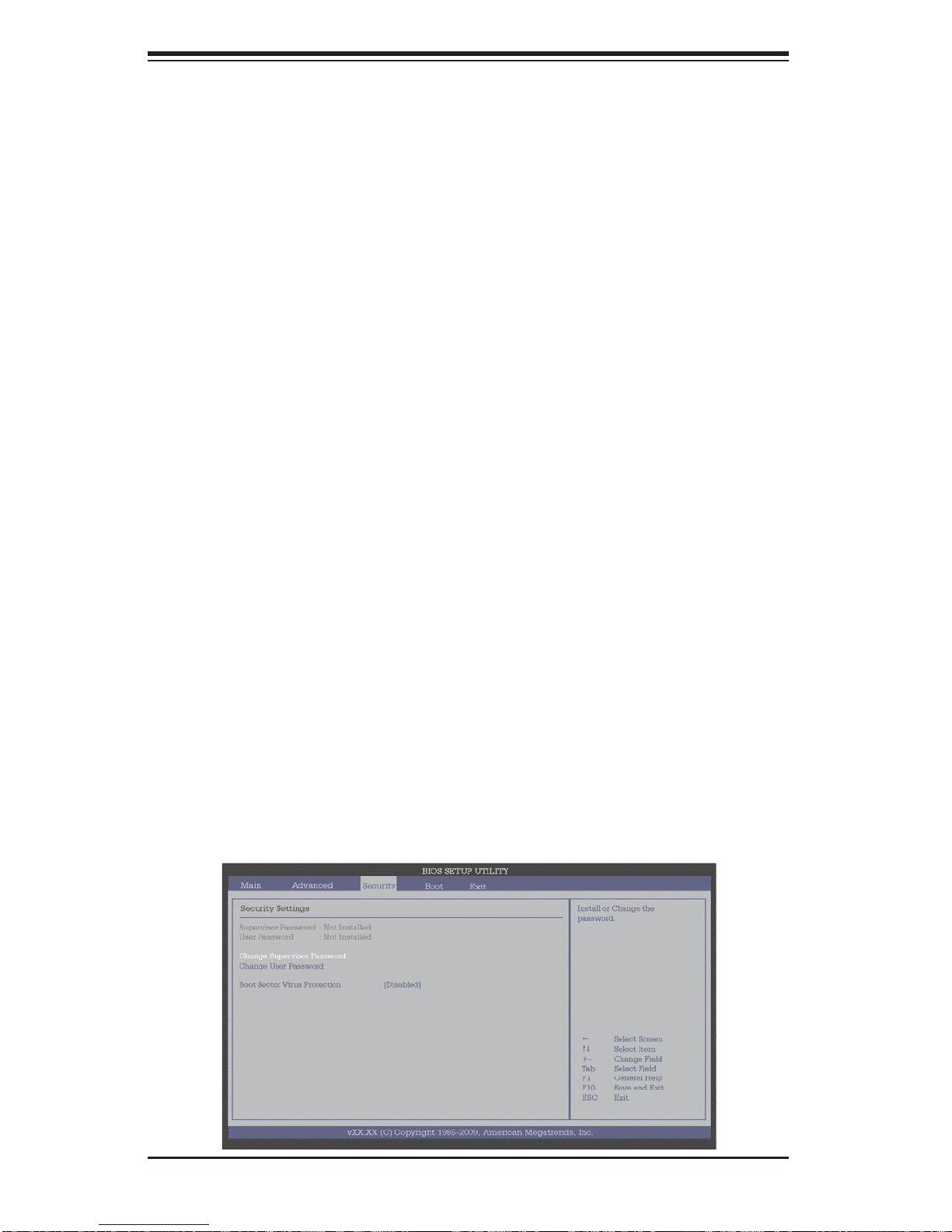
SuperWorkstation 7046A-6 User's Manual
XTrusted Computing (Optional for OEM only)
TCG/TPM (Trusted Platform Module) Support
Select Yes on this item and enable the TPM jumper on the motherboard to enable
TCG (TPM 1.1/1.2)/TPM support in order to improve data integrity and network
security. The options are No and Yes.
If this feature is set to Yes, the following items will display:
TPM Enable/Disable Status
This item displays the status of TPM Enabled/Disabled state.
TPM Owner Status
This item displays the status of TPM Ownership.
XDMI Event Log
View Event Log
Use this option to view the System Event Log.
Mark all events as read
This option marks all events as read. The options are OK and Cancel.
Clear event log
This option clears the Event Log memory of all messages. The options are OK
and Cancel.
7-4 Security Settings
The AMI BIOS provides a Supervisor and a User password. If you use both passwords, the Supervisor password must be set fi rst.
7-20
Page 89

Chapter 7: BIOS
Supervisor Password
This item indicates if a Supervisor password has been entered for the system. "Not
Installed" means a Supervisor password has not been used.
User Password
This item indicates if a user password has been entered for the system. "Not I nstalle d" means that a u ser password has not been used.
Change Supervisor Password
Select this feature and press <Enter> to access the submenu, and then enter a
new Supervisor Password.
User Access Level (Available when Supervisor Password is set as above)
Use this feature to set the user's access level. The options are:
Full Access
• : Select this item to grant a user a full access to the Setup Utility.
View Only: Select this item to allow the user to access the Setup Utility without
•
making changes.
Limited: Select this item to allow the user a limited access to the Setup Utility
•
and making changes. such as Date and Time
No Access: Select this item to prevent the user from accessing the Setup Util-
•
ity.
Change User Password
Select this feature and press <Enter> to access the submenu, and then enter a
new User Password.
Clear User Password (Available only if User Password has been set)
This item allows you to clear a user password after it has been entered.
Password Check
This item allows you to check a password after it has been entered. The options
are Setup and Always.
Boot Sector Virus Protection
When Enabled, the AMI BIOS displays a warning when any program (or virus) issues a Disk Format command or attempts to write to the boot sector of the hard
disk drive. The options are Enabled and Disabled.
7-21
Page 90
SuperWorkstation 7046A-6 User's Manual
7-5 Boot Confi guration
Use this feature to confi gure boot settings.
Main Advanced
Boot Settings
Boot Device Priority
Hard Disk Drives
Removable Drives
Security
vXX.XX (C) Copyright 1985-2009, American Megatrends, Inc.
XBoot Device Priority
BIOS SETUP UTILITY
Boot
Exit
Specifies the
Boot Device
Priority sequence.
Select Screen
Select Item
+- Change Field
Tab Select Field
F1 General Help
F10 Save and Exit
ESC Exit
This feature allows the user to specify the sequence of priority for the Boot Device.
The settings are 1st boot device, 2nd boot device, 3rd boot device, 4th boot device,
5th boot device and Disabled.
1st Boot Device - 1st Floppy Drive
•
2nd Boot Device - [USB: XXXXXXXXX]•
XHard Disk Drives
This feature allows the user to specify the boot sequence from all available hard
disk drives. The settings are Disabled and a list of all hard disk drives that have
been detected (i.e., 1st Drive, 2nd Drive, 3rd Drive, etc).
XRemovable Drives
This feature allows the user to specify the boot sequence from available Removable
Drives. The settings are 1st boot device, 2nd boot device, and Disabled.
1st Drive
•
2nd Drive - [USB: XXXXXXXXX]•
XCD/DVD Drives
This feature allows the user to specify the boot sequence from available CD/DVD
Drives (i.e., 1st Drive, 2nd Drive, etc).
7-22
Page 91
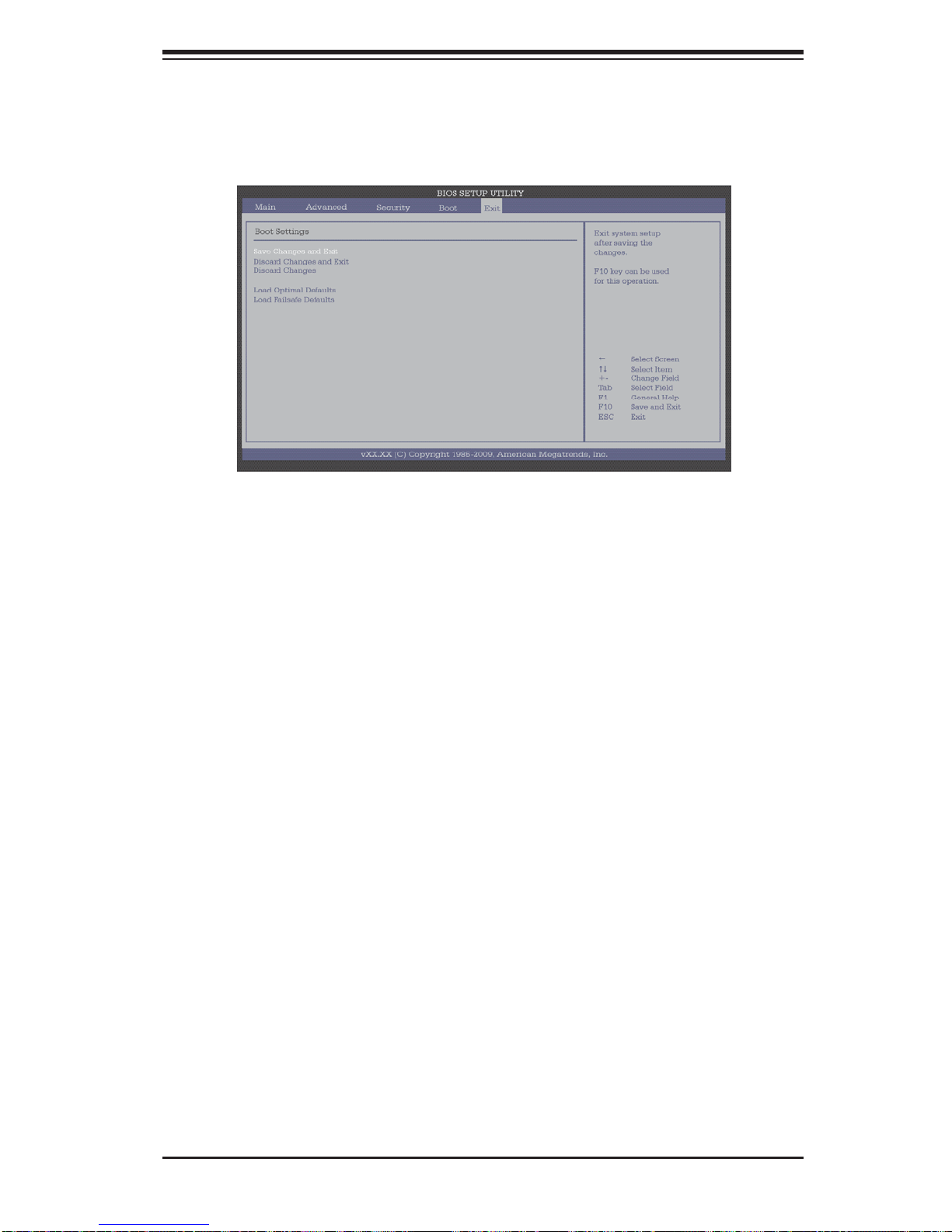
Chapter 7: BIOS
7-6 Exit Options
Select the Exit tab from the AMI BIOS Setup Utility screen to enter the Exit BIOS
Setup screen.
Save Changes and Exit
When you have completed the system confi guration changes, select this option
to leave the BIOS Setup Utility and reboot the computer, so the new system confi guration parameters can take effect. Select Save Changes and Exit from the Exit
menu and press <Enter>.
Discard Changes and Exit
Select this option to quit the BIOS Setup without making any permanent changes
to the system confi guration, and reboot the computer. Select Discard Changes and
Exit from the Exit menu and press <Enter>.
Discard Changes
Select this option and press <Enter> to discard all the changes and return to the
AMI BIOS Utility Program.
Load Optimal Defaults
To set this feature, select Load Optimal Defaults from the Exit menu and press
<Enter>. Then, select OK to allow the AMI BIOS to automatically load Optimal Defaults to the BIOS Settings. The Optimal settings are designed for maximum system
performance, but may not work best for all computer applications.
Load Fail-Safe Defaults
To set this feature, select Load Fail-Safe Defaults from the Exit menu and press
<Enter>. The Fail-Safe settings are designed for maximum system stability, but not
for maximum performance.
7-23
Page 92

SuperWorkstation 7046A-6 User's Manual
Notes
7-24
Page 93
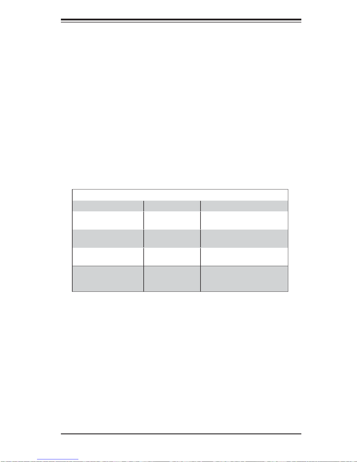
Appendix A: BIOS POST Error Codes
Appendix A
BIOS Error Beep Codes
During the POST (Power-On Self-Test) routines, which are performed each time
the system is powered on, errors may occur.
Non-fatal errors are those which, in most cases, allow the system to continue the
boot-up process. The error messages normally appear on the screen.
Fatal errors are those which will not allow the system to continue the boot-up procedure. If a fatal error occurs, you should consult with your system manufacturer
for possible repairs.
A-1 BIOS Error Beep Codes
BIOS Error Beep Codes
Beep Code Error Message Description
1 beep Refresh Circuits have been reset.
(Ready to power up)
5 short beeps + 1 long
beep
8 beeps Display memory
1 continuous beep
(with the front panel
OH LED on)
Memory error No memory detected in the
system
Video adapter missing or with
read/write error
System Overheat 1 continuous beep with the
faulty memory
front panel OH LED on
A-1
Page 94

SuperWorkstation 7046A-6 User's Manual
Notes
A-2
Page 95

Appendix B: System Specifi cations
Appendix B
System Specifi cations
Processors
Two Intel 5500 series (LGA 1366) processors
Note: Please refer to our web site for a complete listing of supported processors.
Chipset
Intel 5520 + ICH10R
BIOS
32 Mb AMI S PI Flash ROM
Memory Capacity
Twelve DIMM sockets supporting up to 96 GB or registered ECC or up to 24 GB
of unbuffered ECC or non-ECC DDR3-1333/1066/800 SDRAM
Note: See the memory section in Chapter 5 for details.
SAS Contr oller
LSI 200 8 controller for eight SAS ports (RAID 0, 1 and 10 suppor ted, RAID 5
supported with optional AOC-IMRR Akey-LSI-2008)
SATA Controll er
Intel on-chip (ICH10R) controller for six 3 Gb/s Serial ATA ports (RAID 0, 1, 5 and
10 su pp or t ed)
Drive Bays
Eight hot- swap dr ive bays to hou se eight S AS drive s
Perip hera l Dri ve Bays
Three 5. 25" dr ive bays
Expansion Slots
Supports the use of seven standard size PCI add-on cards: one PCI-E x16 slot,
two PCI-E 2.0 x4 (in x8) slots, one PCI-E x4 (in x8) slot, two 64-bit PCI-X 133/100
slots and one 64-bit PCI-X 133 slot
B-1
Page 96

SuperWorkstation 7046A-6 User's Manual
Serverboard
X8DA6 (Extended ATX form factor)
Dimensions: 13.05" x 12.075" (331.5 x 306.7 mm)
Chassis
SC743TQ-865-SQ Form Factor: tower/4U rackmount
Dimensions (as tower): (WxHxD) 7 x 17.2 x 25.5 in. (178 x 437 x 648 mm)
Weight
Gross (Bare Bone): 64 lbs. (29.1 kg.)
System Cooling
Two 8-cm low-noise chassis fans
One 9-cm low-noise exhaust fan
System Input Requirements
AC Input Voltage: 100-240V AC auto-range
Rated Input Current: 100 (12A) - 240V (6A)
Rated Input Frequency: 50 to 60 Hz
PFC Power Supply
Rated Output Power: 865W (Part# PWS-865-PQ)
Rated Output Voltages: +3.3V (30A), +5V (30A), +12V
(70A), +5Vsb (6.5A)
ALL
Operating Environment
Operating Temperature: 10º to 35º C (50º to 95º F)
Non-operating Temperature: -40º to 70º C (-40º to 158º F)
Operating Relative Humidity: 8% to 90% (non-condensing)
Non-operating Relative Humidity: 5 to 95% (non-condensing)
B-2
Page 97

Appendix B: System Specifi cations
Regulatory Compliance
Electromagnetic Emissions: FCC Class B, EN 55022 Class B, EN 61000-3-2/-33, CISPR 22 Class B
Electromagnetic Immunity: EN 55024/CISPR 24, (EN 61000-4-2, EN 61000-4-3,
EN 61000-4-4, EN 61000-4-5, EN 61000-4-6, EN 61000-4-8, EN 61000-4-11)
Safety: CSA/EN/IEC/UL 60950-1 Compliant, UL or CSA Listed (USA and
Canada), CE Marking (Europe)
California Best Management Practices Regulations for Perchlorate Materials:
This Perchlorate warning applies only to products containing CR (Manganese
Dioxide) Lithium coin cells. “Perchlorate Material-special handling may apply. See
www.dtsc.ca.gov/hazardouswaste/perchlorate”
B-3
Page 98

SuperWorkstation 7046A-6 User's Manual
The products sold by Supermicro are not intended for and will not be used in life support systems,
medical equipment, nuclear facilities or systems, aircraft, aircraft devices, aircraft/emergency communication devices or other critical systems whose failure to perform be reasonably expected to
result in signifi cant injury or loss of life or catastrophic property damage. Accordingly, Supermicro dis-
claims any and all liability, and should buyer use or sell such products for use in such ultra-hazardous
applications, it does so entirely at its own risk. Furthermore, buyer agrees to fully indemnify, defend
and hold Supermicro harmless for and against any and all claims, demands, actions, litigation, and
proceedings of any kind arising out of or related to such ultra-hazardous use or sale.
(continued from front)
B-4
 Loading...