

Supero SuperWorkstation 7044A-8, SuperWorkstation 7044A-82, SuperWorkstation 7044A-i, SuperWorkstation 7044A-i2 User Manual
Page 1
®
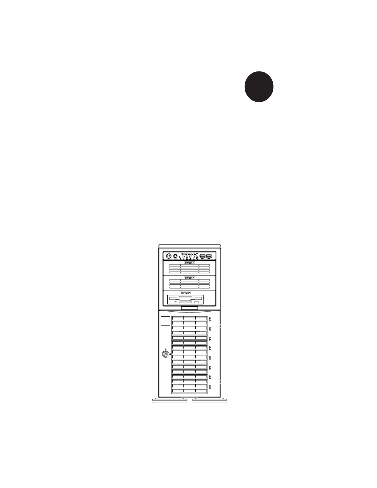
SUPERWORKSTATION 7044A-82
SUPERWORKSTATION 7044A-8
SUPERWORKSTATION 7044A-i2
SUPERWORKSTATION 7044A-i
USER’S MANUAL
1.0a
SUPER
Page 2

The information in this User’s Manual has been carefully reviewed and is believed to be
accurate. The vendor assumes no responsibility for any inaccuracies that may be
contained in this document, makes no commitment to update or to keep current the
information in this manual, or to notify any person or organization of the updates.
Please
Note: For the most up-to-date version of this manual, please see our
web site at www.supermicro.com.
SUPERMICRO COMPUTER reserves the right to make changes to the product described in
this manual at any time and without notice. This product, including software, if any, and
documentation may not, in whole or in part, be copied, photocopied, reproduced, translated
or reduced to any medium or machine without prior written consent.
IN NO EVENT WILL SUPERMICRO COMPUTER BE LIABLE FOR DIRECT, INDIRECT,
SPECIAL, INCIDENTAL, SPECULATIVE OR CONSEQUENTIAL DAMAGES ARISING FROM
THE USE OR INABILITY TO USE THIS PRODUCT OR DOCUMENTATION, EVEN IF
ADVISED OF THE POSSIBILITY OF SUCH DAMAGES. IN PARTICULAR, THE VENDOR
SHALL NOT HAVE LIABILITY FOR ANY HARDWARE, SOFTWARE, OR DATA STORED
OR USED WITH THE PRODUCT, INCLUDING THE COSTS OF REPAIRING, REPLACING,
INTEGRATING, INSTALLING OR RECOVERING SUCH HARDWARE, SOFTWARE, OR
DATA.
Any disputes arising between manufacturer and customer shall be governed by the laws of
Santa Clara County in the State of California, USA. The State of California, County of
Santa Clara shall be the exclusive venue for the resolution of any such disputes.
Supermicro's total liability for all claims will not exceed the price paid for the hardware
product.
Unless you request and receive written permission from SUPER MICRO COMPUTER, you
may not copy any part of this document.
Information in this document is subject to change without notice. Other products and
companies referred to herein are trademarks or registered trademarks of their respective
companies or mark holders.
Copyright © 2005 by SUPER MICRO COMPUTER INC.
All rights reserved.
Printed in the United States of America
Page 3

iii
Preface
Preface
About This Manual
This manual is written for professional system integrators and PC technicians.
It provides information for the installation and use of the SuperWorkstation 7044A82/7044A-8/7044A-i2/7044A-i. Installation and maintainance should be performed by experienced technicians only.
The SuperWorkstation 7044A-82/7044A-8/7044A-i2/7044A-i is a high-end, dual
processor workstation based on the SC743S1-645/SC743i-645 4U tower/
rackmount chassis and the X6DA8-G2/X6DA8-G/X6DAE-G2/X6DAE-G, a dual
processor serverboard that supports single or dual Intel® XeonTM processors at
a Front Side (System) Bus speed of 800 MHz.
Manual Organization
Chapter 1: Introduction
The first chapter provides a checklist of the main components included with the
server system and describes the main features of the SUPER X6DA8-G2/X6DA8G/X6DAE-G2/X6DAE-G serverboard and the SC743S1-645/SC743i-645 chassis,
which comprise the SuperWorkstation 7044A-82/7044A-8/7044A-i2/7044A-i.
Chapter 2: Server Installation
This chapter describes the steps necessary to install the system into a rack and
check out the server configuration prior to powering up the system. If your server
was ordered without processor and memory components, this chapter will refer
you to the appropriate sections of the manual for their installation.
Chapter 3: System Interface
Refer here for details on the system interface, which includes the functions and
information provided by the control panel on the chassis as well as other LEDs
located throughout the system.
Page 4

SUPERWORKSTATION 7044A-82/7044A-8/7044A-i2/7044A-i Manual
iv
Chapter 4: System Safety
You should thoroughly familiarize yourself with this chapter for a general overview
of safety precautions that should be followed when installing and servicing the
SuperWorkstation 7044A-82/7044A-8/7044A-i2/7044A-i.
Chapter 5: Advanced Serverboard Setup
Chapter 5 provides detailed information on the X6DA8-G2/X6DA8-G/X6DAE-G2/
X6DAE-G serverboard, including the locations and functions of connections,
headers and jumpers. Refer to this chapter when adding or removing processors
or main memory and when reconfiguring the serverboard.
Chapter 6: Advanced Chassis Setup
Refer to Chapter 6 for detailed information on the SC743S1-645/SC743i-645
server chassis. You should follow the procedures given in this chapter when
installing, removing or reconfiguring SCSI or peripheral drives and when replacing
system power supply units and cooling fans.
Chapter 7: BIOS
The BIOS chapter includes an introduction to BIOS and provides detailed information on running the CMOS Setup Utility.
Appendix A: BIOS POST Codes
Appendix B: Software Installation
Appendix C: System Specifications
Page 5

v
Preface
Notes
Page 6

vi
Table of Contents
Preface
About This Manual ....................................................................................................... ii i
Manual Organization .................................................................................................... ii i
Chapter 1: Introduction
1-1 Overview ............................................................................................................ 1- 1
1-2 Serverboard Features ...................................................................................... 1-2
1- 3 Server Chassis Features ................................................................................ 1 -3
1- 4 Contacting Supermicro ................................................................................... 1 -6
Chapter 2: Quick Setup
2-1 Overview ............................................................................................................ 2- 1
2-2 Unpacking the SuperWorkstation System.................................................... 2-1
2- 3 Preparing for Setup ......................................................................................... 2-1
2-4 Installing the System into a Rack ................................................................. 2-4
2- 5 Checking the Serverboard Setup ................................................................... 2 -8
2-6 Checking the Drive Bay Setup....................................................................... 2-9
Chapter 3: System Interface
3-1 Overview ............................................................................................................ 3- 1
3-2 Control Panel Buttons ..................................................................................... 3-1
Power ......................................................................................................... 3 -1
Reset.......................................................................................................... 3-1
3- 3 Control Panel LEDs......................................................................................... 3-2
Power ......................................................................................................... 3 -2
HDD ............................................................................................................ 3-2
NIC.............................................................................................................. 3-2
Overheat ..................................................................................................... 3 -2
Power Fail.................................................................................................. 3- 3
3- 4 SCSI Drive LEDs ............................................................................................. 3-3
3-5 LAN (Ethernet) Port LEDs.............................................................................. 3-3
Chapter 4: System Safety
4-1 Electrical Safety Precautions ...........................................................................4-1
4- 2 General Safety Precautions .............................................................................4-2
4-3 ESD Safety Precautions...................................................................................4-3
4- 4 Operating Precautions ......................................................................................4-4
SUPERWORKSTATION 7044A-82/7044A-8/7044A-i2/7044A-i Manual
Page 7

Chapter 5: Advanced Serverboard Setup
5-1 Handling the Serverboard ............................................................................. 5-1
5-2 PGA Processor and Heatsink Installation .................................................. 5-2
5-3 Connecting Cables ......................................................................................... 5-5
Connecting Data Cables ......................................................................... 5-5
Connecting Power Cables...................................................................... 5-5
Connecting the Control Panel ................................................................ 5-6
5- 4 I/O Ports ........................................................................................................... 5-7
5- 5 Installing Memory............................................................................................ 5-7
5- 6 Adding PCI Cards ........................................................................................... 5-9
5-7 Serverboard Details ....................................................................................... 5-9
X6DA8-G2/X6DA8-G/X6DAE-G2/X6DAE-G Layout .......................... 5-10
X6DA8-G2/X6DA8-G/X6DAE-G2/X6DAE-G Quick Reference ......... 5-11
5-8 Connector Definitions .................................................................................. 5-12
ATX Power Connector.......................................................................... 5-12
Processor Power Connector............................................................... 5-12
NMI Button ............................................................................................... 5-12
Power LED .............................................................................................. 5-12
HDD LED .................................................................................................. 5-13
NIC LEDs ................................................................................................. 5-13
Overheat LED (OH) ............................................................................... 5-13
Power Fail LED ...................................................................................... 5-13
Reset Button ........................................................................................... 5-14
Power Button ......................................................................................... 5-14
Chassis Intrusion ................................................................................... 5-14
Universal Serial Bus (USB0/1) ............................................................ 5-14
Fan Headers ........................................................................................... 5-15
Serial Ports ............................................................................................. 5-15
GLAN 1/2 (Ethernet Ports) ................................................................... 5-15
ATX PS/2 Keyboard and Mouse Ports ............................................... 5-15
Power LED/Speaker/NMI ....................................................................... 5-16
Wake-On-Ring ........................................................................................ 5-16
Wake-On-LAN ........................................................................................ 5-16
SMB .......................................................................................................... 5-16
Power Fault ............................................................................................ 5-17
Keylock Fault .......................................................................................... 5-17
Power Supply Fail Alarm Reset .......................................................... 5-17
5- 9 Jumper Settings ............................................................................................ 5-18
Explanation of Jumpers ........................................................................ 5-18
vii
Table of Contents
Page 8

viii
CMOS Clear............................................................................................. 5-18
GLAN Enable/Disable............................................................................. 5-19
SCSI Controller Enable/Disable ............................................................ 5-19
SCSI Termination Enable/Disable......................................................... 5-19
Watch Dog Enable/Disable ................................................................... 5-20
AC'97 Audio Enable/Disable ................................................................. 5-20
Third Power Supply Alarm Enable/Disable ........................................ 5-21
Power Force On Enable/Disable ......................................................... 5-21
5-10 Onboard Indicators ...................................................................................... 5-22
GLAN1/GLAN2 LEDs ............................................................................. 5-22
5-11 Parallel Port, Floppy/Hard Disk Drive and SCSI Connections............... 5-22
Parallel Port Connector ......................................................................... 5-22
Floppy Connector ................................................................................... 5-23
IDE Connectors ...................................................................................... 5-23
Ultra320 SCSI Connectors .................................................................... 5-24
Chapter 6: Advanced Chassis Setup
6- 1 Static-Sensitive Devices ................................................................................. 6- 1
6- 2 Front Control Panel ........................................................................................ 6-3
6-3 System Fans ................................................................................................... 6-4
Fan Failure................................................................................................ 6-4
Replacing System Fans .......................................................................... 6-4
6-4 Drive Bay Installation ..................................................................................... 6-6
SCSI Drives ............................................................................................... 6-6
Installing Components in the 5.25" Drive Bays .................................. 6-9
6-5 Power Supply ............................................................................................... 6-10
Power Supply Failure ........................................................................... 6-10
Replacing the Power Supply ............................................................... 6-10
Chapter 7: BIOS
7- 1 Introduction...................................................................................................... 7-1
7- 2 Running Setup................................................................................................. 7-2
7- 3 Main BIOS Setup............................................................................................. 7-2
7-4 Advanced Setup............................................................................................. 7-7
7-5 Security .......................................................................................................... 7-19
7- 6 Boot ................................................................................................................ 7-21
7-7 Exit .................................................................................................................. 7-22
SUPERWORKSTATION 7044A-82/7044A-8/7044A-i2/7044A-i Manual
Page 9

Table of Contents
ix
Appendices:
Appendix A: BIOS POST Codes ........................................................................... A-1
Appendix B: Software Installation ....................................................................... B-1
Appendix C: System Specifications .................................................................... C- 1
Page 10

Notes
x
SUPERWORKSTATION 7044A-82/7044A-8/7044A-i2/7044A-i Manual
Page 11

Chapter 1
Introduction
1-1 Overview
The Supermicro SuperWorkstation 7044A-82/7044A-8/7044A-i2/7044A-i is a
high-end dual processor workstation that can be utilized either in a tower or in
a rackmount configuration. The 7044A-82/7044A-8/7044A-i2/7044A-i is comprised of two main subsystems: the SC743S1-645/SC743i-645 high-end server
chassis and the X6DA8-G2/X6DA8-G/X6DAE-G2/X6DAE-G dual XeonTM processor serverboard. Please refer to our web site for information on operating systems that have been certified for use with your workstation.
In addition to the serverboard and chassis, various hardware components have
been included with the SuperWorkstation, as listed below:
z One (1) 3.5" floppy drive [FPD-PNSC-02(1)]
z Four (4) hot-swap 8-cm chassis PWM fans (FAN-0074)
z One (1) air shroud (CSE-PT54)
z Two (2) 5.25" dummy drive trays [CSE-PT36(B)]
z One (1) front control panel cable (CBL-0049)
z One (1) round floppy cable (CBL-0040)
z One (1) IDE cable (CBL-0036, 7044A-i2/7044A-i only)
z One (1) round CD-ROM cable (CBL-0039)
z One (1) I/O shield (CSE-PT57)
z SCSI Accessories (7044A-82/7044A-8 only)
One (1) SCSI backplane with SAF-TE (CSE-SCA-743S1)
One (1) 2' SCSI drop cable (CBL-037-U320)
Eight (8) SCA 1-inch high SCSI drive carriers [CSE-PT17(B)]
z Optional: Two (2) Xeon passive heatsinks (SNK-P0010)
One (1) rackmount kit [CSE-PT26(B)]
Chapter 1: Introduction
1-1
Page 12

1-2
SUPERWORKSTATION 7044A-82/7044A-8/7044A-i2/7044A-i Manual
1-2 Serverboard Features
At the heart of the 7044A-82/7044A-8/7044A-i2/7044A-i lies the X6DA8-G2/
X6DA8-G/X6DAE-G2/X6DAE-G, a dual processor serverboard based on Intel's
E7525 chipset and designed to provide maximum performance. Below are the
main features of the X6DA8-G2/X6DA8-G/X6DAE-G2/X6DAE-G. (See Figure 1-1
for a block diagram of the E7525 chipset).
Processors
The X6DA8-G2/X6DA8-G/X6DAE-G2/X6DAE-G supports single or dual 604-pin
Intel Xeon processors at a FSB speed of 800 MHz. Please refer to the
serverboard description pages on our web site for a complete listing of supported
processors (http://www.supermicro.com).
Memory
The X6DA8-G2/X6DAE-G2 has eight 240-pin DIMM slots that can support up to
16 GB of registered ECC DDR2-400 (PC3200) SDRAM. The memory is an
interleaved configuration, which requires modules of the same size and speed to
be installed in pairs.
The X6DA8-G/XDAE-G has eight 184-pin DIMM slots that can support up to 16
GB of registered ECC DDR333 or 32 GB of registered ECC DDR266 SDRAM. The
memory is an interleaved configuration, which requires modules of the same size
and speed to be installed in pairs.
Onboard SCSI (X6DA8-G2/X6DA8-G only)
Onboard SCSI is provided with an Adaptec AIC-7902 SCSI chip, which supports
dual channel, Ultra320 SCSI at a throughput of 320 MB/sec for each channel.
The X6DA8-G2/X6DA8-G provides two LVD Ultra320 SCSI ports.
PCI Expansion Slots
The X6DA8-G2/X6DA8-G/X6DAE-G2/X6DAE-G has six PCI expansion slots,
which includes one x16@4GB/sec PCI-Express slot, one x4@2GB/sec PCIExpress slot, three 64-bit PCI-X slots (one 64-bit PCI-X 133 slot, one PCI-X 100
slot and one PCI-X 100MHz ZCR slot) and one 32-bit 33MHz PCI slot (w/PCI
graphics card support).
Page 13

1-3
Chapter 1: Introduction
Onboard Controllers/Ports
One floppy drive controller and two onboard ATA/100 controllers are provided to
support up to four hard drives or ATAPI devices. The color-coded I/O ports
include two COM ports, a parallel port, four USB 2.0 ports, PS/2 mouse and
keyboard ports and Line-In, Line-Out and Mic jacks. Two front side USB ports
are also included on the front of the chassis. The X6DA8-G2 and X6DAE-G2 have
two and the X6DA8-G and X6DAE-G have one gigabit Ethernet port.
Other Features
Other onboard features that promote system health include onboard voltage
monitors, a chassis intrusion header, auto-switching voltage regulators, chassis
and CPU overheat sensors, virus protection and BIOS rescue.
1-3 Server Chassis Features
The SuperWorkstation 7044A-82/7044A-8/7044A-i2/7044A-i is a scaleable server
platform designed with today's most state-of-the-art features. The following is a
general outline of the main features of the SC743S1-645/SC743i-645 server chassis. (7044A-82/7044A-8: SC743S1-645 7044A-i2/7044A-i: SC743i-645
Note: The SC743S1-645 and SC743i-645 are two versions of the same chassis.
The only difference between them is the SC743S1-645 is equipped with a SCSI
backplane and drive trays while the SC743i-645 is not.
System Power
The 7044A-82/7044A-8/7044A-i2/7044A-i features a single 645W power supply.
This power supply unit has been designed to operate at a low noise level to make
it ideal for use in a workstation environment.
SCSI Subsystem (7044A-82/7044A-8 only)
The SCSI subsystem supports up to eight 80-pin SCA Ultra320 SCSI hard drives.
(Any standard 1" drives are supported. SCA = Single Connection Attachment.)
The SCSI drives are connected to a single-channel SCA backplane with SAF-TE.
The SCSI drives are also hot-swap units. A RAID controller card can be used with
the SCA backplane to provide data security.
Note: The operating system you use must have RAID support to enable the hotswap capability of the SCSI drives.
Page 14

1-4
SUPERWORKSTATION 7044A-82/7044A-8/7044A-i2/7044A-i Manual
Front Control Panel
The SuperWorkstation 7044A-82/7044A-8/7044A-i2/7044A-i's control panel provides you with system monitoring and control. LEDs indicate system power,
HDD activity, network activity, overheat condition and power supply failure. A
main power button and a system reset button are also included.
Note: the power supply fail LED is intended for use with redundant power supply
systems and so is not needed for the 7044A-82/7044A-8/7044A-i2/7044A-i.
I/O Backplane
The SC743S1-645/SC743i-645 is an ATX form factor chassis that can be used as
a tower or mounted in a 4U rackmount configuration. The I/O backplane provides
six expansion slots, two COM ports, a parallel port, four USB 2.0 ports, PS/2
mouse and keyboard ports, one or two (depending on the serverboard) gigabit
Ethernet port(s) and Line-In, Line-Out and Microphone jacks (see Figure 5-3).
Cooling System
The SC743S1-645/SC743i-645 chassis has an innovative cooling design that
includes four 8-cm hot-plug PWM (Pulse Width Modulation) system cooling fans
located in the middle of the chassis. The chassis fans work with an air shroud
to cool the areas where the most heat is generated. All chassis fans operate
continuously at 5000 rpm.
Page 15
1-5
Chapter 1: Introduction
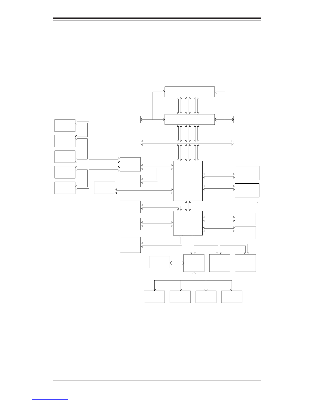
Figure 1-1. Intel E7525 Chipset:
System Block Diagram
Note: This is a general block diagram. Please see Chapter 5 for details.
MC H
NOCONA P R OCE S S OR# 2VRM
CL OCK
ADDR
CTRL
DAT A
NOCONA P R OCE S S OR# 1
ADDR
CTRL
DAT A
DAT A
ADDR
CTRL
ICH5R
HUB
DDRI I - 4 0 0
A
PXH
B
PCI EXP. A
1 PCI - X
SLOT 3
1 PCI - X
PCI - X BUS( 100 MHZ)
Gbi t L AN
SLOT 2
J13
PCI - X BUS( 100 MHZ)
J14
1 PCI - EXP
SLOT 4
J17
PCI EXP. B, C ( X16)
J15
1 PCI - EXP
S L OT 6
DI MMs
IDE
PRI / SEC
UDMA/ 100
X8X4
X4
DI MMs
0, 1
SATA
SATA
LPC BUSUS B
US B P OR T
0, 1, 2, 3,
BMC CON. FWHLPC I / O
PARAL LEL
PORT
MS .
FDD. SER. 1
SER. 2
KB.
4 DDR I I - 400
4 DDR I I - 400
DDRI I - 4 0 0
SCSI
7902
PCI BUS( 32- BI T)
PCI 32 BI T
S L OT 5
AC 9 7
J19
1 PCI - X
SLOT 1
J12
H/ W
MO N I T O R
5, 6, 7, 8
Page 16

1-6
SUPERWORKSTATION 7044A-82/7044A-8/7044A-i2/7044A-i Manual
1-4 Contacting Supermicro
Headquarters
Address: SuperMicro Computer, Inc.
980 Rock Ave.
San Jose, CA 95131 U.S.A.
Tel: +1 (408) 503-8000
Fax: +1 (408) 503-8008
Email: [email protected] (General Information)
[email protected] (Technical Support)
Web Site: www.supermicro.com
Europe
Address: SuperM icro Computer B.V.
Het Sterrenbeeld 28, 5215 ML
's-Hertogenbosch, The Netherlands
Tel: +31 (0) 73-6400390
Fax: +31 (0) 73-6416525
Email: [email protected] (General Information)
[email protected] (Technical Support)
[email protected] (Customer Support)
Asia-Pacific
Address: SuperMicro, Taiwan
4F, No. 232-1, Liancheng Rd.
Chung-Ho 235, Taipei, Taiwan, R.O.C.
Tel: +886-(2) 8226-3990
Fax: +886-(2) 8226-3991
Web Site: www.supermicro.com.tw
Technical Support:
Email: [email protected]
Tel: 886-2-8228-1366, ext. 132 or 139
Page 17

Chapter 2: Server Installation
2-1
Chapter 2
Server Installation
2-1 Overview
This chapter provides a quick setup checklist to get your SuperWorkstation
7044A-82/7044A-8/7044A-i2/7044A-i up and running. Following these steps in
the order given should enable you to have the system operational within a minimum amount of time. This quick setup assumes that your system has come to
you with the processors and memory preinstalled. If your system is not already
fully integrated with a serverboard, processors, system memory etc., please turn
to the chapter or section noted in each step for details on installing specific
components. The SuperWorkstation 7044A-82/7044A-8/7044A-i2/7044A-i may
be employed either as a tower or rackmounted as a 4U chassis. If using it
in a tower configuration, please read Server Precautions in the next section
and then skip ahead to Section 2-5.
2-2 Unpacking the System
You should inspect the box the system was shipped in and note if it was damaged in any way. If the server itself shows damage you should file a damage
claim with the carrier who delivered it.
Decide on a suitable location for the SuperWorkstation 7044A-82/7044A-8/
7044A-i2/7044A-i. It should be situated in a clean, dust-free area that is well
ventilated. Avoid areas where heat, electrical noise and electromagnetic fields
are generated. You will also need it placed near a grounded power outlet. Read
the Rack and Server Precautions in the next section.
2-3 Preparing for Setup
The box the system was shipped in may include two sets of rail assemblies, two
rail mounting brackets and mounting screws needed for installing the system into
a rack (optional kit). Follow the steps in the order given to complete the installation process in a minimum amount of time. Please read this section in its
entirety before you begin the installation procedure outlined in the sections that
follow.
Page 18
2-2
SUPERWORKSTATION 7044A-82/7044A-8/7044A-i2/7044A-i Manual
Choosing a Setup Location:
- Leave enough clearance in front of the system to enable you to open
the front door completely (~25 inches).
- Leave approximately 30 inches of clearance in the back of the system
to allow for sufficient airflow and ease in servicing.
- This product is for installation in a Restricted Access Location only (dedicated equipment rooms, service closets, etc.)
Rack Precautions:
- Ensure that the leveling jacks on the bottom of the rack are fully extended
to the floor with the full weight of the rack resting on them.
- In single rack installation, stabilizers should be attached to the rack.
- In multiple rack installations, the racks should be coupled together.
- Always make sure the rack is stable before extending a component
from the rack.
- You should extend only one component at a time - extending two or
more simultaneously may cause the rack to become unstable.
Server Precautions:
- Review the electrical and general safety precautions in Chapter 4.
- Determine the placement of each component in the rack before you
install the rails.
- Install the heaviest server components on the bottom of the rack first, and
then work up.
- Use a regulating uninterruptible power supply (UPS) to protect the
server from power surges, voltage spikes and to keep your system operating in case of a power failure.
- Allow the hot plug SCSI drives and power supply units to cool before
touching them.
- Always keep the rack's front door and all panels and components on
the servers closed when not servicing to maintain proper cooling.
!
!
Warnings and Precautions!
Page 19

Chapter 2: Server Installation
2-3
Rack Mounting Considerations
Ambient Operating Temperature
If installed in a closed or multi-unit rack assembly, the ambient operating
temperature of the rack environment may be greater than the ambient temperature of the room. Therefore, consideration should be given to installing
the equipment in an environment compatible with the manufacturer’s maximum rated ambient temperature (Tmra).
Reduced Airflow
Equipment should be mounted into a rack so that the amount of airflow
required for safe operation is not compromised.
Mechanical Loading
Equipment should be mounted into a rack so that a hazardous condition
does not arise due to uneven mechanical loading.
Circuit Overloading
Consideration should be given to the connection of the equipment to the power
supply circuitry and the effect that any possible overloading of circuits might
have on overcurrent protection and power supply wiring. Appropriate consideration of equipment nameplate ratings should be used when addressing this
concern.
Reliable Ground
A reliable ground must be maintained at all times. To ensure this, the rack
itself should be grounded. Particular attention should be given to power
supply connections other than the direct connections to the branch circuit
(i.e. the use of power strips, etc.).
Page 20
2-4
SUPERWORKSTATION 7044A-82/7044A-8/7044A-i2/7044A-i Manual
2-4 Installing the System into a Rack
This section provides information on installing the system into a rack unit. Rack
installation requires the use of the optional rackmount kit [CSE-PT26(B)]. If the
system has already been mounted into a rack or if you are using it as a tower,
you can skip ahead to Sections 2-5 and 2-6. There are a variety of rack units
on the market, which may mean the assembly procedure will differ slightly. The
following is a guideline for installing the workstation into a rack with the rack rails
provided in the rackmount kit. You should also refer to the installation instructions that came with the rack unit you are using.
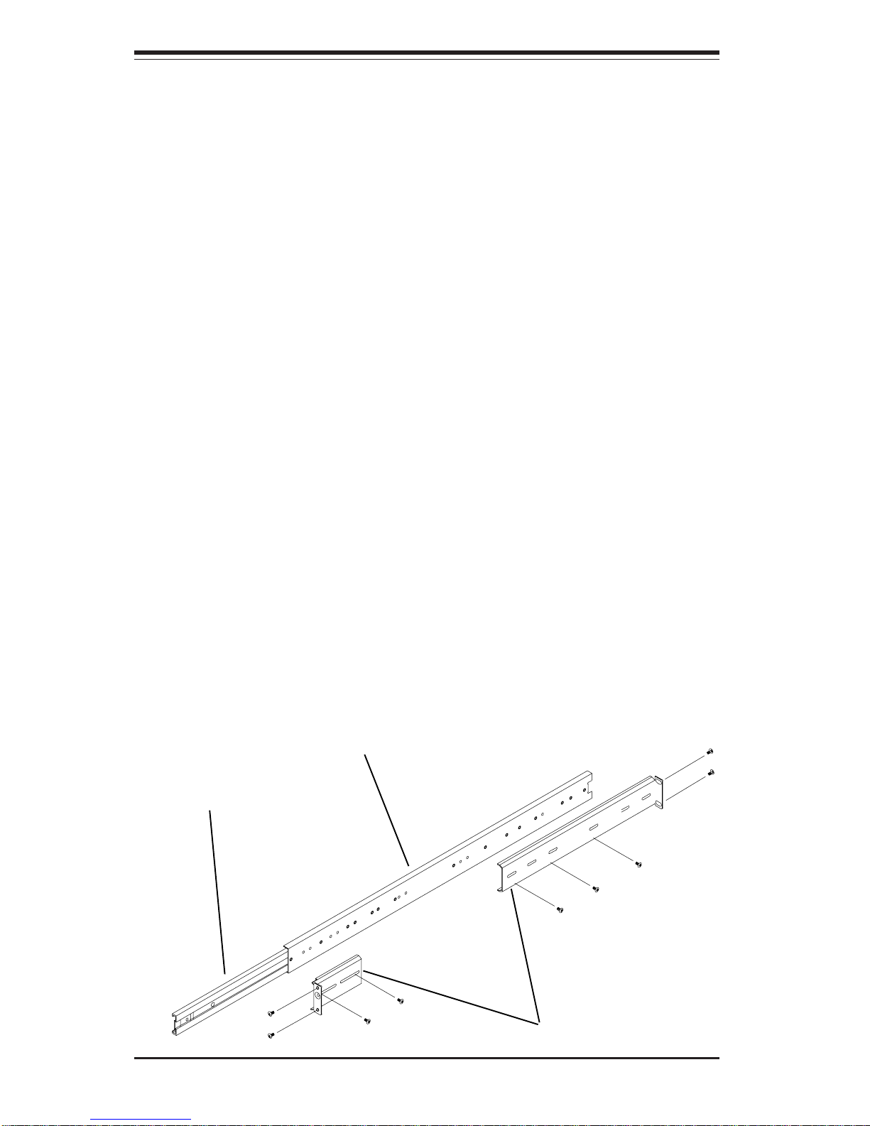
Identifying the Sections of the Rack Rails:
The optional rackmount kit (CSE-PT26 or CSE-PT26B - black) includes two rack
rail assemblies. Each of these assemblies consist of three sections: an inner
fixed chassis rail that secures to the chassis, an outer rack rail that secures
directly to the rack itself and two rail brackets, which also attack to the rack (see
Figure 2-1.) The inner and outer rails must be detached from each other to
install.
To remove the inner chassis rail, pull it out as far as possible - you
should hear a "click" sound as a locking tab emerges from inside the rail
assembly and locks the inner rail. Depress the locking tab to pull the
inner rail completely out. Do this for both assemblies (one for each side).
Figure 2-1. Identifying the Sections of the Rack Rails
Inner rail
Outer rail
Rail brackets
Page 21
Chapter 2: Server Installation
2-5
Installing the Chassis Rails:
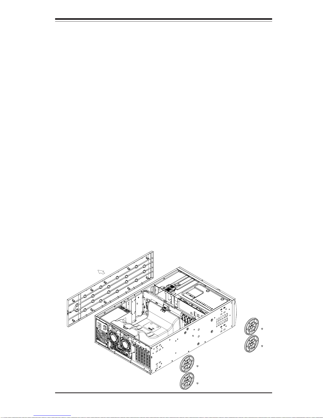
You will need to remove the top bezel cover and the feet to add rack rails to the
chassis. First, remove the top and right covers (top and left covers when standing
as a tower chassis) by first removing the screws that secure them to the chassis.
Depress the button on the top (side if tower) of the chassis to release the cover
and then pull the cover off. Then unscrew the four feet and remove them from the
chassis (see Figure 2-2).
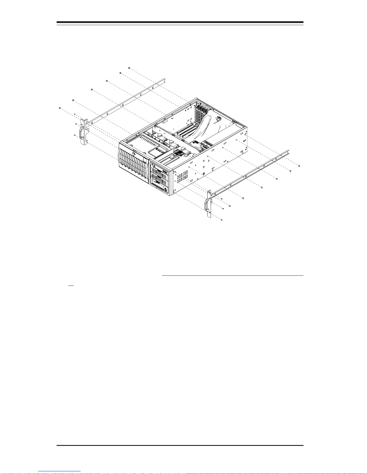
You can now attach rack rails to the top and bottom (now the sides) of the
chassis. First add the rack handles. Then position the inner chassis rail
sections you just removed along the side of the chassis making sure the screw
holes line up. Note that these two rails are left/right specific. Screw the rail
securely to the side of the chassis (see Figure 2-3). Repeat this procedure for
the other rail on the other side of the chassis. You will also need to attach the
rail brackets when installing into a telco rack.
Locking Tabs: As mentioned, the chassis rails have a locking tab, which serves
two functions. The first is to lock the server into place when installed and pushed
fully into the rack, which is its normal position. Secondly, these tabs also lock
the server in place when fully extended from the rack. This prevents the server
from coming completely out of the rack when you pull it out for servicing.
Figure 2-2. Preparing to Install the Chassis Rails
Page 22
2-6
SUPERWORKSTATION 7044A-82/7044A-8/7044A-i2/7044A-i Manual
Installing the Rack Rails:
Determine where you want to place the SuperWorkstation 7044A-82/7044A-8/
7044A-i2/7044A-i in the rack. (See Rack and Server Precautions in Section 2-
3.) Position the fixed rack rail/sliding rail guide assemblies at the desired
location in the rack, keeping the sliding rail guide facing the inside of the rack.
Screw the assembly securely to the rack using the brackets provided. Attach
the other assembly to the other side of the rack, making both are at the exact
same height and with the rail guides facing inward.
Figure 2-3. Installing the Rails to the Chassis
Page 23
Chapter 2: Server Installation
2-7
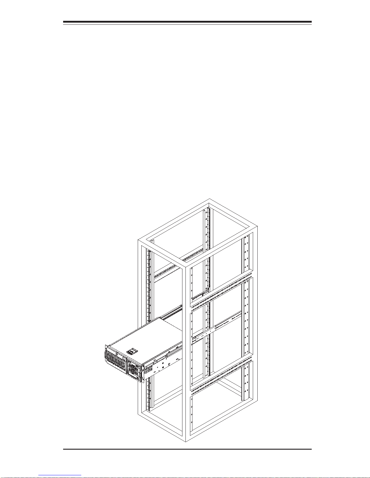
Figure 2-4. Installing the Server into a Rack
Installing the Server into the Rack:
You should now have rails attached to both the chassis and the rack unit. The
next step is to install the server into the rack. You should have two brackets in
the rack mount kit. Install these first keeping in mind that they are left/right
specific (marked with "L" and "R"). Then, line up the rear of the chassis rails with
the front of the rack rails. Slide the chassis rails into the rack rails, keeping the
pressure even on both sides (you may have to depress the locking tabs when
inserting).
When the server has been pushed completely into the rack, you should hear the
locking tabs "click". Finish by inserting and tightening the thumbscrews that
hold the front of the server to the rack (see Figure 2-4).
Page 24

2-8
SUPERWORKSTATION 7044A-82/7044A-8/7044A-i2/7044A-i Manual
2-5 Checking the Serverboard Setup
After setting up the the system, you will need to open the unit to make sure the
serverboard is properly installed and all the connections have been made.
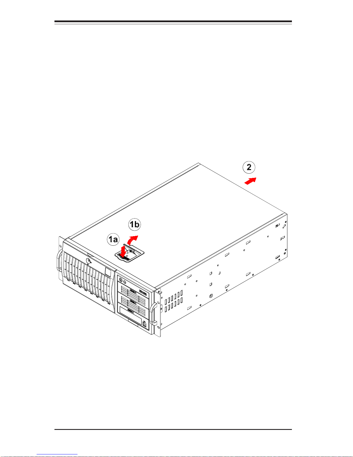
1. Accessing the inside of the system (see Figure 2-5):
(If rack mounted, first release the retention screws that secure the unit to the
rack. Grasp the two handles on either side and pull the unit straight out until
it locks (you will hear a "click").) There are two screws that secure the cover
to the chassis - remove these first. Depress the button on the top (side if
tower) of the chassis to release the cover. You can then lift the cover from
the chassis to gain full access to the inside of the server.
2. Check the CPUs (processors):
You should have one or two processors already installed into the
serverboard. Each processor should have its own heatsink attached.
See Chapter 5 for instructions on processor installation.
3. CPU clock ratio setting:
The CPU speed should be automatically detected. If not, you will need to
set the correct speed with the BIOS Setup utility. See the Frequency
Ratio setting in BIOS (Chapter 7) to set the processor speed.
4. Check the system memory:
Your workstation may have come with system memory already installed.
Make sure all DIMMs are fully seated in their slots. For details on adding
system memory, refer to Chapter 5.
5. Installing add-on cards:
If desired, you can install add-on cards to the system. See Chapter 5 for
details on installing PCI add-on cards.
6. Check all cable connections and airflow:
Make sure all power and data cables are properly connected and not
blocking the chassis airflow. See Chapter 5 for details on cable connections.
Page 25

Chapter 2: Server Installation
2-9
2-6 Checking the Drive Bay Setup
Next, you should check to make sure the peripheral drives and the SCSI
drives and SCA backplane have been properly installed and all connections
have been made. (SCSI applies to 7044A-82/7044A-8 only.)
1. Accessing the drive bays:
All drives can be accessed from the front of the server. For servicing
the CD-ROM, IDE hard drives and floppy drives, you will need to remove
the top/left chassis cover. The SCSI disk drives can be installed and
removed from the front of the chassis without removing any chassis
covers.
2. Installing components into the 5.25" drive bays:
To install components into the 5.25" drive bays, you must first remove the top/
left chassis cover as described in the previous section. Refer to Chapter 6 for
details.
3. Installing CD-ROM and floppy disk drives:
Refer to Chapter 6 if you need to reinstall a CD-ROM and/or floppy disk
drive to the system.
4. Check the SCSI disk drives:
Depending upon your system's configuration, your system may have one
or more drives already installed. If you need to install SCSI drives, please
refer to Chapter 6.
5. Check the airflow:
Airflow is provided by four hot-swap 8-cm chassis fans working in conjunction
with an air shroud. The system component layout was carefully designed to
promote sufficient airflow through the chassis. Also note that all power and
data cables have been routed in such a way that they do not block the airflow
generated by the fans. Keep this in mind when you reroute them after working
on the system.
Page 26
2-10
SUPERWORKSTATION 7044A-82/7044A-8/7044A-i2/7044A-i Manual
6. Supplying power to the system:
The last thing you must do is to provide input power to the system. Plug the
power cord from the power supply unit into a high-quality power strip that offers
protection from electrical noise and power surges. It is recommended that you
use an uninterruptible power supply (UPS). Finally, depress the power on
button on the front of the chassis.
Figure 2-5. Accessing the Inside of the System
(Rack Configuration shown)
Page 27

Chapter 3: System Interface
3-1
Chapter 3
System Interface
3-1 Overview
There are several LEDs on the control panel as well as two for each SCSI drive
carrier (7044A-82/7044A-8 only) and the Ethernet port(s). These LEDs are to
keep you constantly informed of the overall status of the system and the activity
and health of specific components. There are also two buttons on the chassis
control panel.
3-2 Control Panel Buttons
There are two push-button buttons located on the front of the chassis. These are
(in order from left to right) a power on/off button and a reset button.
z POWER: This is the main power button, which is used to apply or turn off
the main system power. Turning off system power with this button removes the
main power but keeps standby power supplied to the system.
z RESET: Use the reset button to reboot the system.
Page 28
3-2
SUPERWORKSTATION 7044A-82/7044A-8/7044A-i2/7044A-i Manual
3-3 Control Panel LEDs
The control panel located on the front of the SC743S1-645/SC743i-645 chassis
has six LEDs that provide you with critical information related to different parts
of the system. This section explains what each LED indicates when illuminated
and any corrective action you may need to take.
z Power: Indicates external power is being supplied to the system's power
supply unit. This LED should normally be illuminated when the system is operating.
z HDD: Indicates IDE channel activity. On the 7044A-82 and 7044A-8/
7044A-i2 and 7044A-i, this LED indicates SCSI/IDE drive activity when flashing.
z NIC: Indicates network activity on LAN1 when flashing.
z NIC: Indicates network activity on LAN2 when flashing (7044A-82/7044A-
i2 only).
z Overheat: When this LED flashes, it indicates a fan failure. When on
continuously it indicates an overheat condition, which may be caused by cables
obstructing the airflow in the system or the ambient room temperature being too
warm. Check the routing of the cables and make sure all fans are present and
operating normally. You should also check to make sure that the chassis covers
are installed. Finally, verify that the heatsinks are installed properly (see Chapter
5). This LED will remain flashing or on as long as the indicated condition exists.
Page 29

Chapter 3: System Interface
3-3
z Power Fail: Indicates a power supply module has failed. This LED is
inended for use with systems that have redundant power supply modules and
therefore is not used with the SuperWorkstation 7044A-82/7044A-8/7044A-i2/
7044A-i.
3-4 SCSI Drive LEDs (7044A-82/7044A-8 only)
Each SCSI drive carrier has two LEDs.
z Green: When illuminated, the green LED on the front of the SCSI drive
carrier indicates drive activity. A connection to the SCSI SCA backplane
enables this LED to blink on and off when that particular drive is being
accessed.
z Red: A SAF-TE compliant backplane is needed to activate the red
LEDs, which indicate a drive failure. Please refer to Chapter 6 for instructions on replacing failed SCSI drives.
3-5 LAN (Ethernet) Port LEDs
The LAN Ethernet port(s) (located beside the VGA port) each have a yellow and
a green LED. The yellow (left) LED indicates activity while the other (right) LED
may be green, orange or off to indicate the speed of the connection. See the
tables below for the functions associated with these LEDs.
Note: the 7044A-82 and 7044A-i2 have two Ethernet ports. The 7044A-8 and the
7044A-i have a single Ethernet port.
LED
Color
Off
Green
Orange
Defin itio n
No Connection
100 MHz
1 GHz
Gb LAN Right LED
Indicator
LED
Color
Off
Yellow
Defin itio n
Not Ac tiv e
Active
Gb LAN Left LED
Indicator
Page 30

3-4
SUPERWORKSTATION 7044A-82/7044A-8/7044A-i2/7044A-i Manual
Notes
Page 31

Chapter 4: System Safety
4-1
Chapter 4
System Safety
4-1 Electrical Safety Precautions
!
Basic electrical safety precautions should be followed to protect yourself from
harm and the SuperWorkstation 7044A-82/7044A-8/7044A-i2/7044A-i from
damage:
z Be aware of the locations of the power on/off switch on the
chassis as well as the room's emergency power-off switch,
disconnection switch or electrical outlet. If an electrical accident
occurs, you can then quickly remove power from the system.
z Do not work alone when working with high voltage components.
z Power should always be disconnected from the system when
removing or installing main system components, such as the
serverboard, memory modules and the CD-ROM and floppy drives (not
necessary for SCSI drives). When disconnecting power, you should
first power down the system with the operating system and then unplug
the power cord from the power supply unit.
z When working around exposed electrical circuits, another person
who is familiar with the power-off controls should be nearby to
switch off the power if necessary.
z Use only one hand when working with powered-on electrical
equipment. This is to avoid making a complete circuit, which will
cause electrical shock. Use extreme caution when using metal
tools, which can easily damage any electrical components or circuit
boards they come into contact with.
z Do not use mats designed to decrease electrostatic discharge as
protection from electrical shock. Instead, use rubber mats that
have been specifically designed as electrical insulators.
Page 32

4-2
SUPERWORKSTATION 7044A-82/7044A-8/7044A-i2/7044A-i Manual
4-2 General Safety Precautions
Follow these rules to ensure general safety:
z Keep the area around the SuperWorkstation 7044A-82/7044A-8/
7044A-i2/7044A-i clean and free of clutter.
z The SuperWorkstation 7044A-82/7044A-8/7044A-i2/7044A-i weighs
approximately 63 lbs. When lifting the system, two people at either
end should lift slowly with their feet spread out to distribute the
weight. Always keep your back straight and lift with your legs.
z Place the chassis top/side cover and any system components that
have been removed away from the system or on a table so that
they won't accidentally be stepped on.
z While working on the system, do not wear loose clothing such as
neckties and unbuttoned shirt sleeves, which can come into contact
with electrical circuits or be pulled into a cooling fan.
z Remove any jewelry or metal objects from your body, which are
excellent metal conductors that can create short circuits and harm
you if they come into contact with printed circuit boards or areas
!
z The power supply power cord must include a grounding plug and must be
plugged into grounded electrical outlets.
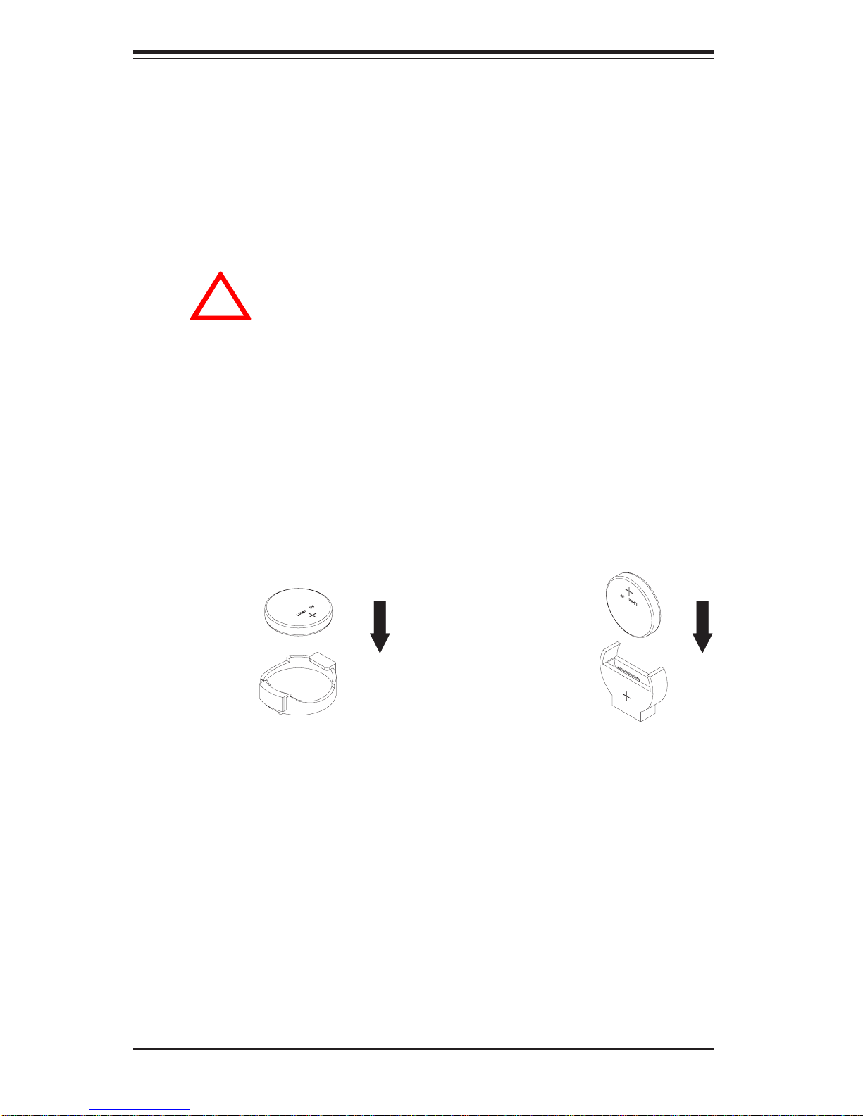
z Serverboard Battery: CAUTION - There is a danger of explosion if
the onboard battery is installed backwards, which will reverse its
polarities. The positive side of the battery should be facing up and
the negative side should facing the serverboard. This battery must
be replaced only with the same or an equivalent type recommended
by the manufacturer. Dispose of used batteries according to the
manufacturer's instructions. See Figure 4-1.
z CD-ROM Laser: CAUTION - this server may have come equipped
with a CD-ROM drive. To prevent direct exposure to the laser beam
and hazardous radiation exposure, do not open the enclosure or
use the unit in any unconventional way.
Page 33
Chapter 4: System Safety
4-3
4-3 ESD Precautions
Electrostatic discharge (ESD) is generated by two objects with
different electrical charges coming into contact with each other. An
electrical discharge is created to neutralize this difference, which can
damage electronic components and printed circuit boards. The
following measures are generally sufficient to neutralize this
difference before contact is made to protect your equipment from ESD:
z Use a grounded wrist strap designed to prevent static discharge.
z Keep all components and printed circuit boards (PCBs) in their
antistatic bags until ready for use.
z Touch a grounded metal object before removing the board from the
antistatic bag.
z Do not let components or PCBs come into contact with your
clothing, which may retain a charge even if you are wearing a wrist
strap.
z Handle a board by its edges only; do not touch its components,
peripheral chips, memory modules or contacts.
z When handling chips or modules, avoid touching their pins.
z Put the serverboard and peripherals back into their antistatic bags
when not in use.
!
where power is present.
z After accessing the inside of the system, close the system back up
and (if rackmounted) secure it to the rack unit with the retention
screws after ensuring that all connections have been made.
Page 34
4-4
SUPERWORKSTATION 7044A-82/7044A-8/7044A-i2/7044A-i Manual
4-4 Operating Precautions
Care must be taken to assure that all chassis covers are in place when
the SuperWorkstation 7044A-82/7044A-8/7044A-i2/7044A-i is operating to
ensure proper cooling. Out of warranty damage to the 7044A-82/7044A-8/
7044A-i2/7044A-i system can occur if this practice is not strictly followed.
!
z For grounding purposes, make sure your computer chassis
provides excellent conductivity between the power supply, the case,
the mounting fasteners and the serverboard.
Figure 4-1. Installing the Onboard Battery
LITHIUM BATTERY
BATTERY HOLDER BATTERY HOLDER
LITHIUM BATTERY
OR
Page 35

Chapter 5: Advanced Serverboard Setup
5-1
Chapter 5
Advanced Serverboard Setup
This chapter covers the steps required to install processors and heatsinks to the
X6DA8-G2/X6DA8-G/X6DAE-G2/X6DAE-G serverboard, connect the data and
power cables and install add-on cards. All serverboard jumpers and connections
are described and a layout and quick reference chart are included in this chapter.
Remember to close the chassis completely when you have finished working on
the serverboard to protect and cool the system sufficiently.
5-1 Handling the Serverboard
Static electrical discharge can damage electronic components. To prevent
damage to printed circuit boards, it is important to handle them very carefully (see Chapter 4). Also note that the size and weight of the serverboard
can cause it to bend if handled improperly, which may result in damage. To
prevent the serverboard from bending, keep one hand under the center of
the board to support it when handling. The following measures are generally sufficient to protect your equipment from static discharge.
Precautions
• Use a grounded wrist strap designed to prevent static discharge.
• Touch a grounded metal object before removing any board from its antistatic bag.
• Handle a board by its edges only; do not touch its components, peripheral chips, memory modules or gold contacts.
• When handling chips or modules, avoid touching their pins.
• Put the serverboard, add-on cards and peripherals back into their antistatic bags when not in use.
Unpacking
The serverboard is shipped in antistatic packaging to avoid static damage.
When unpacking the board, make sure the person handling it is static protected.
Page 36
5-2
SUPERWORKSTATION 7044A-82/7044A-8/7044A-i2/7044A-i Manual
!
5-2 PGA Processor and Heatsink Installation
When handling the processor package, avoid placing direct
pressure on the label area of the fan. Also, do not place the
motherboard on a conductive surface, which can damage the
BIOS battery and prevent the system from booting up.
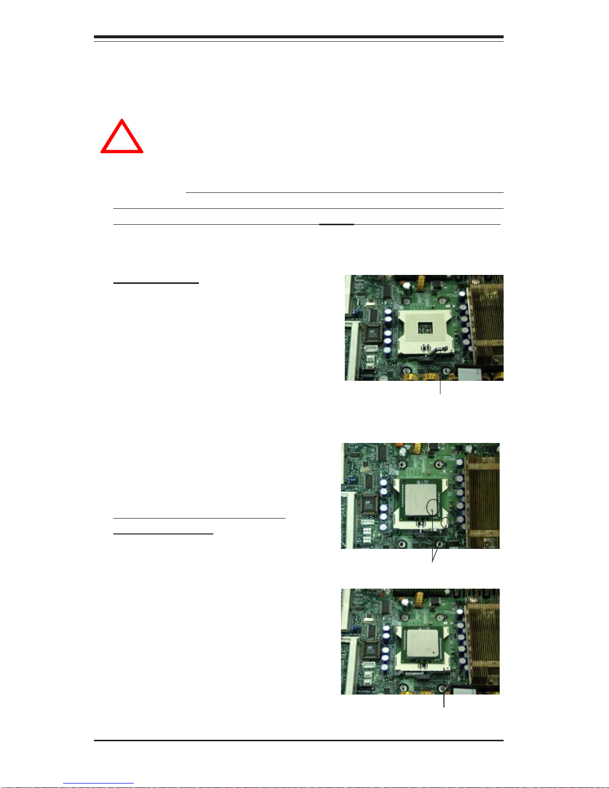
Socket lever
CPU Installation
1. Lift the lever on the CPU socket: Lift
the lever completely as shown on the
picture on the right; otherwise, you will
damage the CPU socket when power
is applied. Install CPU1 first.
IMPORTANT: Always connect the power cord last and always remove it before
adding, removing or changing any hardware components. Make sure that you
install the processor into the CPU socket before you install the CPU heat sink.
Pin 1
2. Insert the CPU in the socket,
making sure that pin 1 of the CPU
aligns with pin 1 of the socket (both
corners are marked with a triangle).
When using only one CPU, install it
into CPU socket #1. (Socket #2 is
automatically disabled if only one
CPU is used.)
3. Press the lever down until you
hear a *click*, which means the
CPU is securely installed in the
CPU socket.
Socket lever in the
locking Position
Page 37
Chapter 5: Advanced Serverboard Setup
5-3
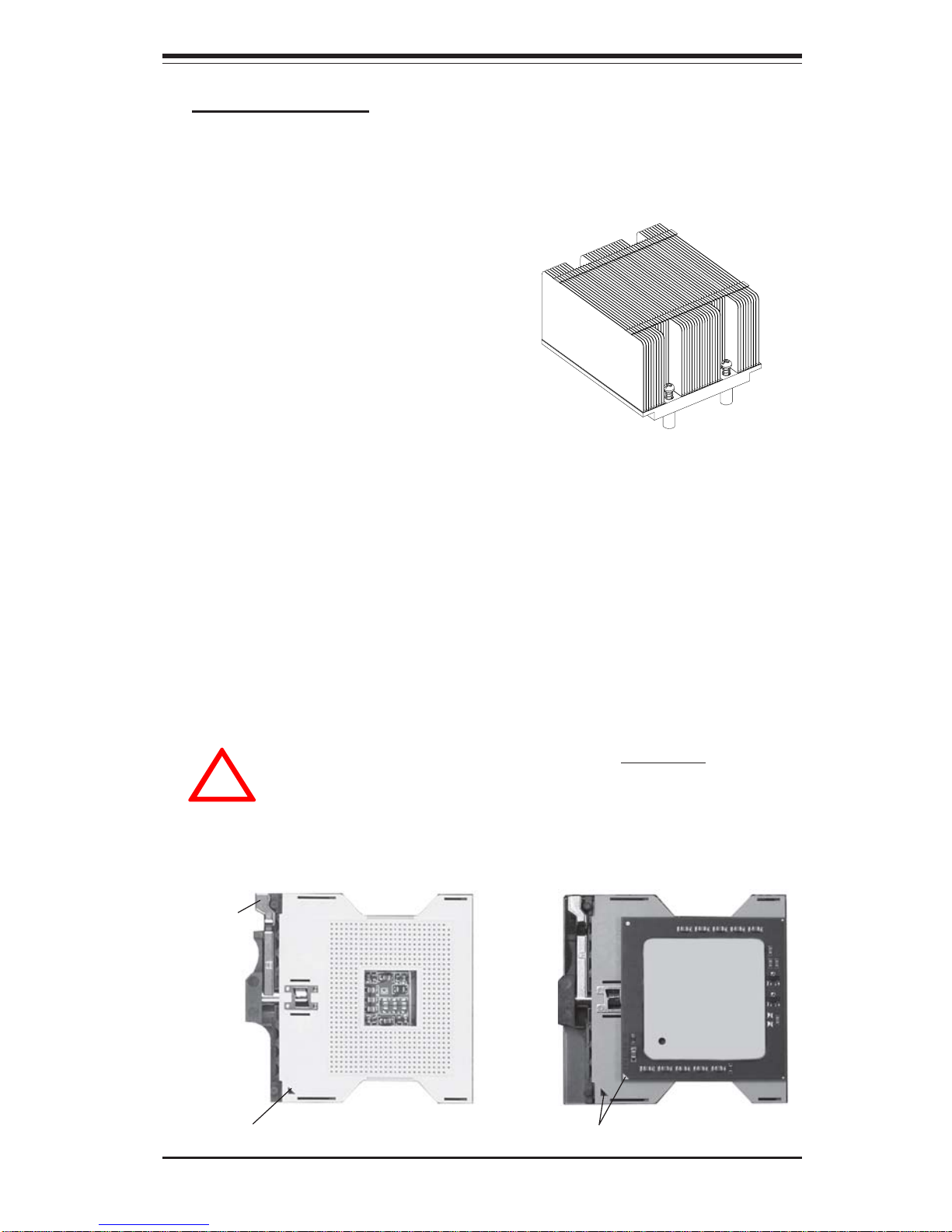
Heatsink Installation*
1. Do not apply any thermal com-
pound to the heatsink or the CPU
die; the required amount has already been applied.
2. Place the heatsink on top of the
CPU so that the four mounting
holes are aligned with those on the
retention mechanism.
3. Screw in two diagonal screws
until snug (do not fully tighten the
screws to avoid possible damage to
the CPU). The screw in the other
two diagonal screws until snug.
4. Finish the installation by fully
tightening all four screws.
Figure 5-1. 604-pin PGA Socket: Empty and with Processor Installed
Warning! Make sure you lift the lever completely when
installing the CPU. If the lever is only partly raised, damage
to the socket or CPU may result.
!
Lever
With processor installed
Triangle (pin 1)
Empty socket
Triangle locating pin 1
*Note: This heatsink (SNK-P0010) is a passive heatink. It is an optional part that
must be purchased separately.
Page 38
5-4
SUPERWORKSTATION 7044A-82/7044A-8/7044A-i2/7044A-i Manual
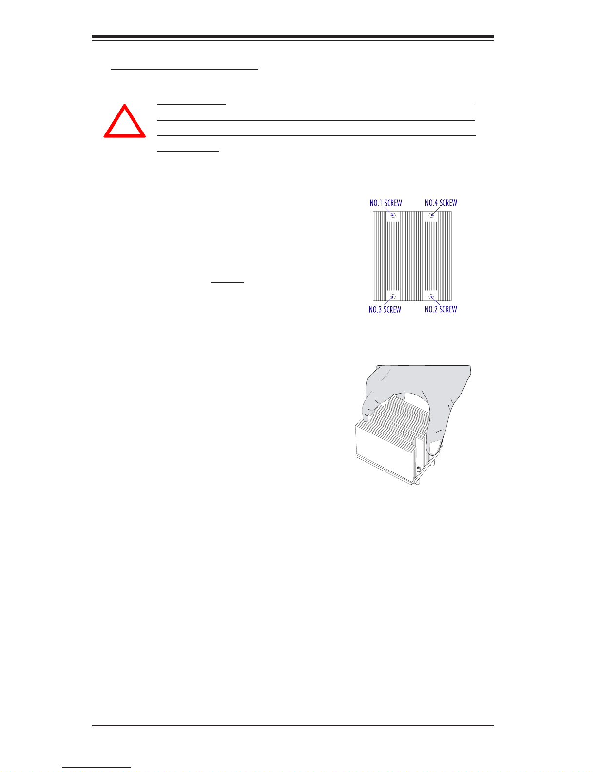
IMPORTANT: Removal of the heatsink or the CPU is not recommended. However, if you do need to remove the heatsink, please
follow the instructions below to prevent damaging the CPU or the
CPU socket.
1. Unscrew and remove the heatsink
screws from the serverboard in the sequence as show in the picture on the right.
2. Hold the heatsink as show in the picture
on the right and gently wriggle the
heatsink to loosen it from the CPU. (Do
not use excessive force when wriggling the
heatsink!!)
3. Once the heatsink has been loosened
from the CPU, remove the heatsink from
the CPU socket.
4. Clean the surface of the CPU and the
heatsink to get rid of the old thermal
grease. Reapply the proper amount of
thermal grease on the surface before you
re-install the heatsink to the CPU.
!
Removing the Heatsink/CPU
Page 39

Chapter 5: Advanced Serverboard Setup
5-5
5-3 Connecting Cables
Now that the processors are installed, the next step is to connect the
cables to the serverboard. These include the data (ribbon) cables for the
peripherals and control panel and the power cables.
Connecting Data Cables
The ribbon cables used to transfer data from the peripheral devices have
been carefully routed in preconfigured systems to prevent them from blocking the flow of cooling air that moves through the system from front to back.
If you need to disconnect any of these cables, you should take care to keep
them routed as they were originally after reconnecting them (make sure the
red wires connect to the pin 1 locations). If you are configuring the system, keep the airflow in mind when routing the cables. The following data
cables (with their motherboard connector locations noted) should be connected. See the serverboard layout figure in this chapter for connector
locations.
z Ultra320 LVD SCSI Cables (JA1, X6DA8-G2/X6DA8-G only)
z IDE#1 Cable (J3, X6DAE-G2/X6DAE-G only)
z Control Panel Cable (JF1, see next page)
z Front Side USB Cable (JD2)
z Floppy Drive Cable (JP8)
Connecting Power Cables
The X6DA8-G2/X6DA8-G/X6DAE-G2/X6DAE-G has a 24-pin primary power supply
connector designated "ATX Power" for connection to the ATX power supply.
Connect the appropriate connector from the power supply to the "ATX Power"
connector to supply power to the serverboard. The 12V 8-pin power connector
at J1D1 and the 12V 4-pin power connector at J32 must also both be connected
to your power supply. See the Connector Definitions section in this chapter for
power connector pin definitions.
Page 40
5-6
SUPERWORKSTATION 7044A-82/7044A-8/7044A-i2/7044A-i Manual
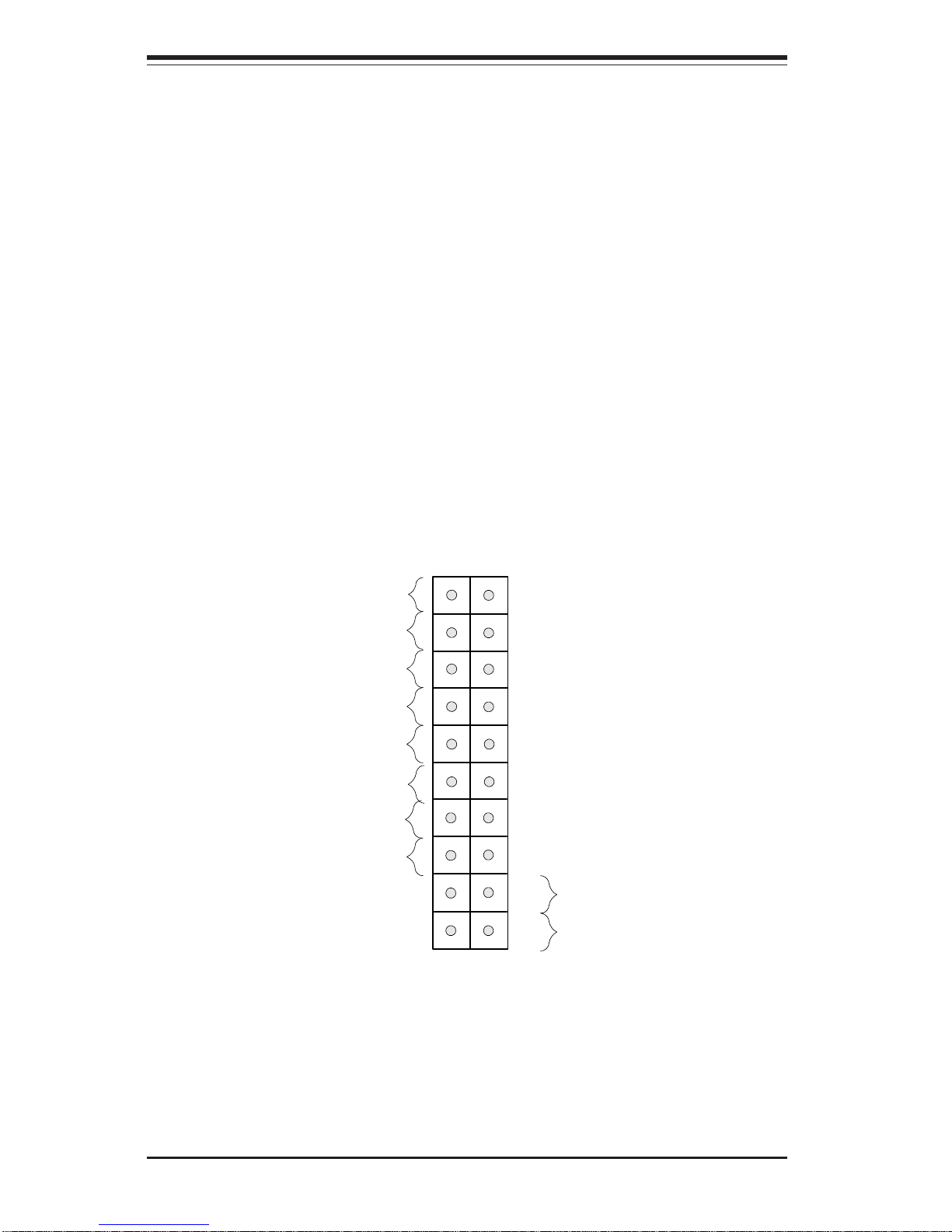
Figure 5-2. JF1 Header Pins
Connecting the Control Panel
JF1 contains header pins for various front control panel connectors. See
Figure 5-2 for the pin locations of the various front control panel buttons and
LED indicators. Please note that even and odd numbered pins are on
opposite sides of each header.
All JF1 wires have been bundled into single ribbon cable to simplify their
connection. Make sure the red wire plugs into pin 1 as marked on the
board. The other end connects to the Control Panel printed circuit board,
located just behind the system status LEDs in the chassis.
See the Connector Definitions section in this chapter for details and pin
descriptions of JF1.
Power Button
Overheat LED
1
NIC1 LED
Reset Button
2
Power Fail LED
HDD LED
Power LED
Reset
Pwr
Vcc
Vcc
Vcc
Vcc
Ground
Ground
1920
Vcc
X
Ground
NMI
X
NIC2 LED*
Vcc
*NIC2 applies only to the X6DA8-G2 and the X6DAE-G2
Page 41
Chapter 5: Advanced Serverboard Setup
5-7
5-4 I/O Ports
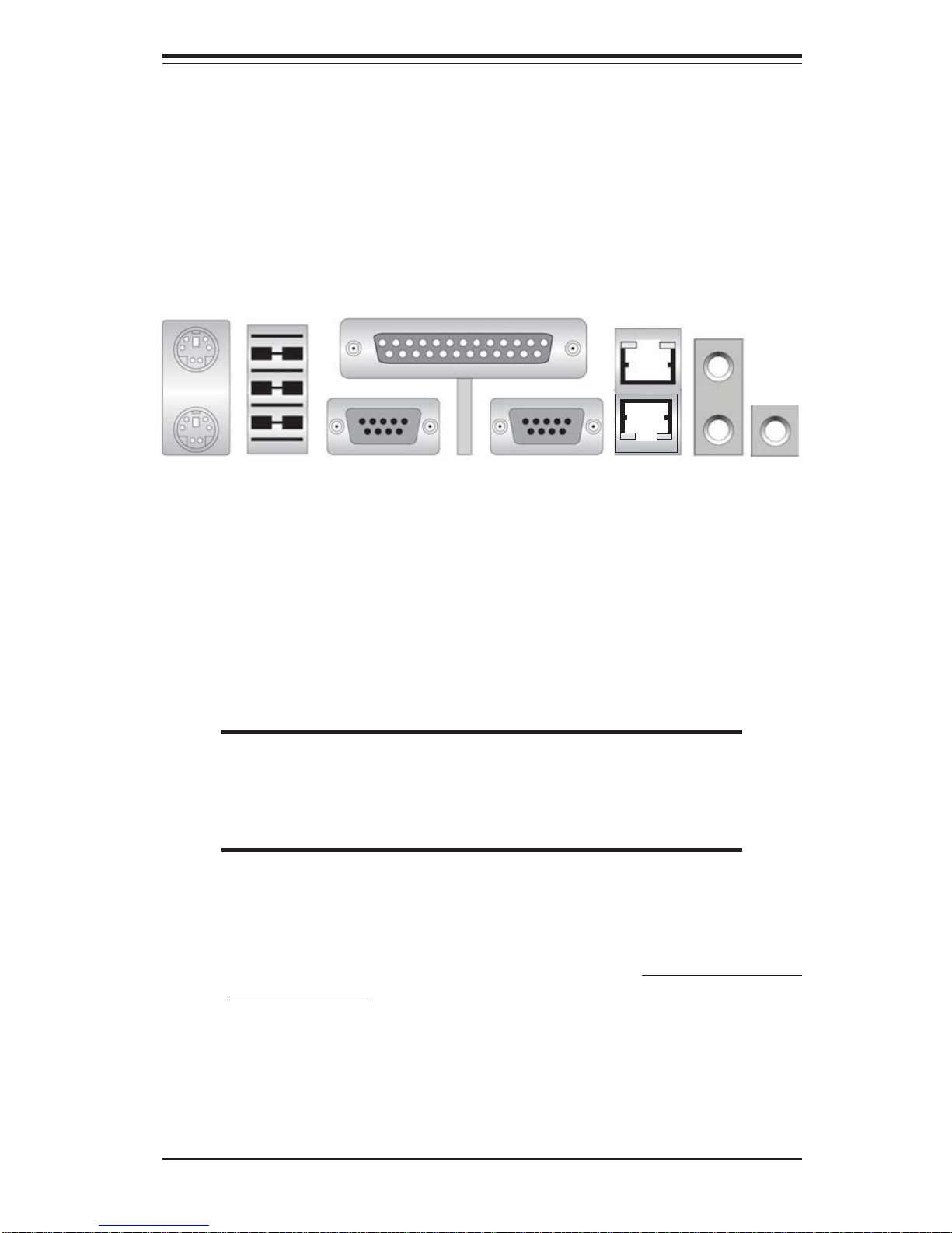
The I/O ports are color coded in conformance with the PC 99 specification. See
Figure 5-3 below for the colors and locations of the various I/O ports.
Figure 5-3. I/O Ports
5-5 Installing Memory
Note: Check the Supermicro web site for recommended memory modules:
http://www.supermicro.com/support/resources/
CAUTION
Exercise extreme care when installing or removing DIMM modules
to prevent any possible damage. Also note that the memory is
interleaved to improve performance (see step 1).
DIMM Installation (See Figures 5-4 and 5-5)
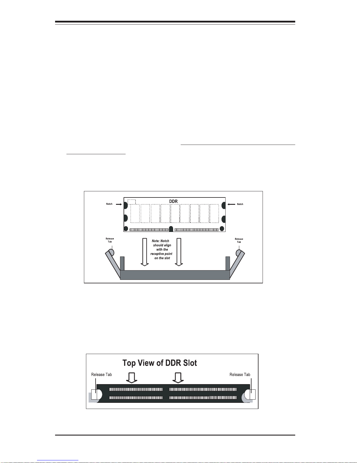
1. Insert the desired number of DIMMs into the memory slots, starting with
Bank #1A. The memory scheme is interleaved so you must install two
modules at a time, beginning with DIMM #1A, then DIMM #1B, and so on.
2. Insert each DIMM module vertically into its slot. Pay attention to the
notch along the bottom of the module to prevent inserting the DIMM
module incorrectly.
3. Gently press down on the DIMM module until it snaps into place in the
slot. Repeat for all modules (see step 1 above).
COM1 COM2 LAN1/2*
KB/Mouse
USB#0-3
Parallel Port
Line-out
Line-In
Mic
*Note: The X6DA8-G and X6DAE-G have only a single LAN (Ethernet) port.
Page 42
5-8
SUPERWORKSTATION 7044A-82/7044A-8/7044A-i2/7044A-i Manual
Figure 5-5. Top View of DIMM Slot
Figure 5-4. Side View of DIMM Installation into Slot
To Install: Insert module vertically and press down until it snaps into
place. Pay attention to the bottom notch.
To Remove: Use your thumbs to gently push each release tab outward
to free the DIMM from the slot.
Memory Support
The X6DA8-G2/X6DAE-G2 has eight 240-pin DIMMs that support up to 16 GB of
registered ECC DDR2-400 (PC3200) SDRAM memory. The X6DA8-G2/X6DAEG2 was designed to support 4 GB modules in each slot, but has only been
verified for up to 2 GB modules.
The X6DA8-G/X6DAE-G has eight 184-pin DIMMs that support up to 16 GB of
registered ECC DDR333 (PC2700) or 32 GB of registered ECC DDR266 (PC2100)
SDRAM memory.
The memory is an interleaved configuration, which requires modules of the same
size and speed to be installed in pairs. You should not mix modules of different
sizes and/or speeds.
Page 43

Chapter 5: Advanced Serverboard Setup
5-9
5-6 Adding PCI Cards
1. PCI slots:
The X6DA8-G2/X6DA8-G/X6DAE-G2/X6DAE-G has has six PCI expansion
slots, which includes one x16@4GB/sec PCI-Express slot, one x4@2GB/
sec PCI-Express slot, three 64-bit PCI-X slots (one 64-bit PCI-X 133 slot, one
PCI-X 100 slot, one PCI-X 100MHz ZCR slot) and one 32-bit 33MHz PCI slot
(w/PCI graphics card support).
2. PCI card installation:
Before installing a PCI add-on card, make sure you install it into a slot that
supports the speed of the card (see step 1, above). Begin by removing the
screw from the PCI slot shield that corresponds to the slot you wish to
populate. Insert the PCI card into the slot on the serverboard, pushing
down with your thumbs evenly on both sides of the card. Finish by securing the card to the chassis with the same screw you removed from the PCI
slot shield. Follow this procedure when adding a card to other slots.
Page 44
5-10
SUPERWORKSTATION 7044A-82/7044A-8/7044A-i2/7044A-i Manual
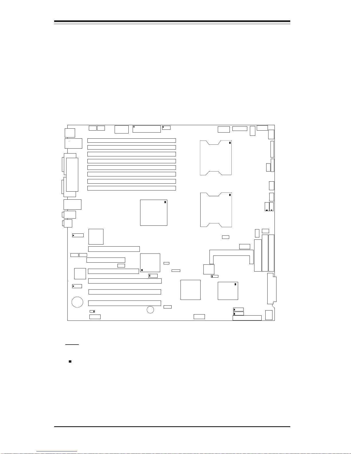
Figure 5-6. SUPER X6DA8-G2/X6DA8-G/X6DAE-G2/X6DAE-G Layout*
(not drawn to scale)
5-7 Serverboard Details
Notes:
Jumpers not noted are for test purposes only.
" " indicates the location of Pin 1.
Only the X6DA8-G2 and X6DA8-G include an onboard SCSI controller.
The X6DA8-G2 and the X6DAE-G2 have two GB LAN ports.
The X6DA8-G and the X6DAE-G have a single GB LAN port.
KB/
Mouse
DIMM 1B Bank 1
SPKR
Tumwater
(North Bridge)
South
Bridge
IPMI 2.0
BIOS
AIC-7902
IDE #1
IDE #2
Floppy
FAN4
JD2
JPA3
JF1
FAN7
CPU1
CPU2
J40
J3J4
JP8
JD1
J24
JLAN1
COM2
COM1
Parrallel
Port
FAN6
FAN5
J32
ATX PWR
J1B4
JPF
PW
Force On
Line In/Line Out
JPC1
SI/O
Slot #6: x16 PCI-Express
Slot #5: PCI (33MHz)
Slot #3: PCI-X (133MHz)
Slot #2: PCI-X (100MHz)
J27
CD1
CD2
Slot #4: PCI-X (100MHz ZCR)
GLAN
CTRL
JPL1
Battery
J22
SCSI Ch B
JPA2
SCSI Ch A
JA1
JA2
FAN3
JPA1
J20
JWD
JK1
Keylock
FAN8
JBT1
FAN1
J1D1
JC2
MicJC1
Slot #4: x4 PCI-Express
JL1
JP13
JP14
JOH1
JP15
JP12
PXH
LAN1/2
JD3
FAN2
JWOL
JWOR1
DIMM 1A Bank 1
DIMM 2B Bank 2
DIMM 2A Bank 2
DIMM 3B Bank 3
DIMM 3A Bank 3
DIMM 4B Bank 4
DIMM 4A Bank 4
J9
USB0/1/
2/3
J23
Page 45

Chapter 5: Advanced Serverboard Setup
5-11
X6DA8-G2/X6DA8-G/X6DAE-G2/X6DAE-G
Quick Reference
Jumper Description Default Setting
JBT1 CMOS Clear See Section 5-9
JP13 3rd Pwr Supply Alarm Enable/Disable Open (Disabled)
JPA1* SCSI Controller Enable/Disable Pins 1-2 (Enabled)
JPA2/JPA3* SCSI Ch. A/B Term. Enable/Disable Open(Enabled)
JPC1 Audio Enable/Disable Pins 1-2 (Enabled)
JPF Power Force On Open (Disabled)
JPL1 Giga-bit LAN Enable/Disable Pins 1-2 (Enabled)
JWD Watch Dog Enable Pins 1-2 (Reset)
Connector Description
J1B4 Primary 24-pin ATX PWR Connector
J1D1 12V 8-pin PWR Connector
COM1, COM2 COM1 and COM2 Serial Port Connectors
DIMM1A-4B Memory (SDRAM) Slots
FAN1-8 CPU FAN1/CPU FAN2/Chassis Fans Headers
J3/J4 IDE#1/#2 Disk Drive Connectors
J9 Keyboard/Mouse
J20 IPMI 2.0 Connector
J22 System Management Bus Connector
J23 Parallel (Printer) Port
J24 PWR System Management Bus
J32 12V 4-pin CPU PWR Connector
J40 Universal Serial Bus Ports 0-3 (backpanel ports)
JA1, JA2* Ultra320 SCSI Channel A, Channel B
JC1 Microphone Jack
JC2 Line In/Out Jacks
JD1 PWR LED (Pins1-3), Speaker (Pins 4-7)
JD2, JD3 USB Ports 6/7, 4/5 (front access ports)
JF 1 Front Panel Control
JK1 Keylock
JL1 Chassis Intrusion Header
JOH1 Overheat LED
JP8 Floppy Disk Drive Connector
JP12 Power Fault Connector
JP14 Power Supply Fail Alarm Reset
JWOL Wake-on-LAN Header
JWOR1 Wake-on-Ring Header
LAN1/2** Gigabit Ethernet Ports
*X6DA8-G2/X6DA8-G only **LAN2 is on the X6DA8-G2/X6DAE-G2 only
Page 46
5-12
SUPERWORKSTATION 7044A-82/7044A-8/7044A-i2/7044A-i Manual
5-8 Connector Definitions
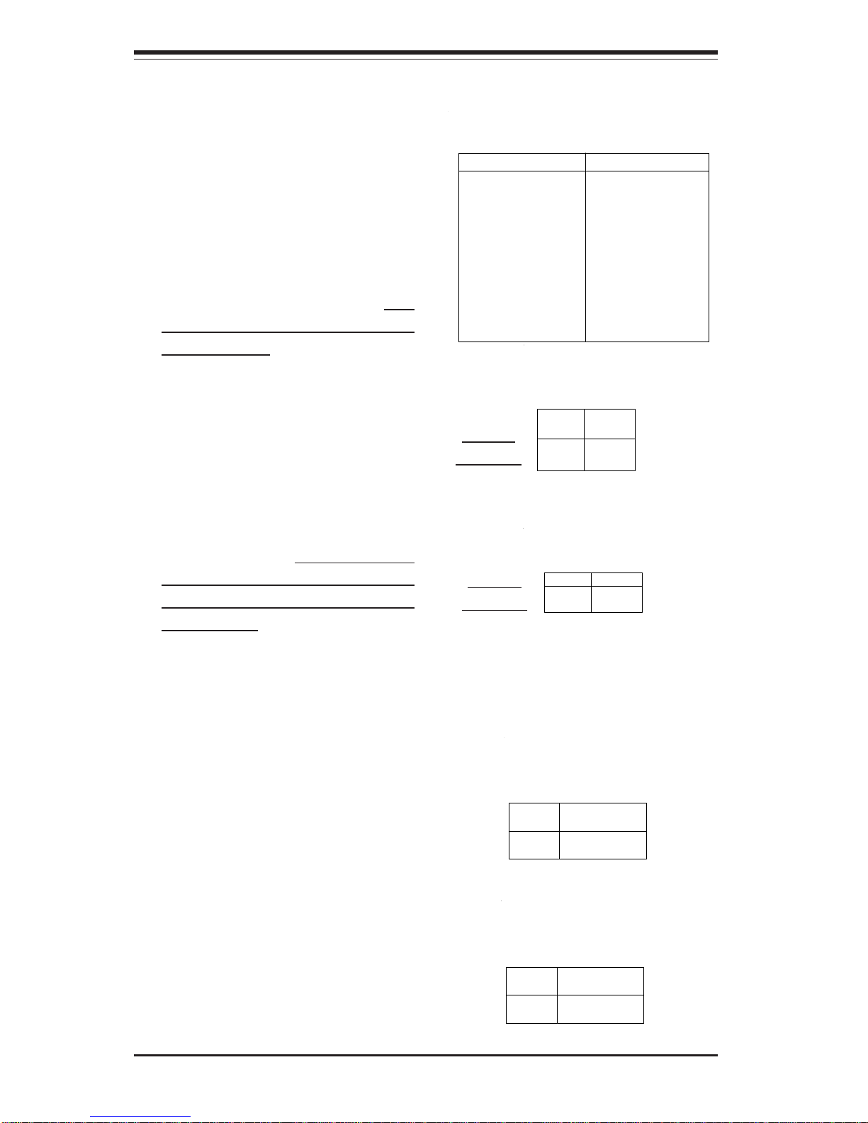
Power LED
The Power LED connection is located on pins 15 and 16 of JF1. Refer to the table on the right for pin
definitions.
ATX Power Connector
The serverboard includes a 24-pin
main power supply connector (J1B4)
and a 4-pin CPU PWR connector
(J32). These power connectors meet
the SSI EPS 12V specification. You
can use a 20-pin connector, but connecting J3 is also required to ensure
sufficient power. See the table on the
right for pin definitions. For CPU
power, please see the item below.
Pin
Number
15
16
Definition
Vcc
Control
PWR_LED Pin Definitions
(JF1)
ATX Power S u pply 24-pin Connector
Pin Definitions (J1B4)
Pin Number Definition
13 +3.3V
14 -12V
15 COM
16 PS_ON#
17 COM
18 COM
19 COM
20 Res(NC )
21 +5V
22 +5V
23 +5V
24 COM
Pin Number Definition
1 +3.3V
2 +3.3V
3 COM
4 +5V
5 COM
6 +5V
7 COM
8 PWR_ OK
9 5VSB
10 +12V
11 +12V
12 +3.3 V
Pins #
1 & 2
3 & 4
Definition
Ground
+12 V
+12V 4-pin Connector
(J32)
Required
Connection
Processor Power
Connector
In addition to the Primary ATX power
connector (above), the 12v 8-pin processor power connector at J1D1
must also be connected to your
power supply. (If an 8-pin cable is
not available, please use two 4-pin
cables.) See the table on the right for
pin definitions.
Pins
1 thru 4
5 thru 8
Definition
Ground
+12v
CPU 8-pin PWR
Connector (J1D1)
Required
Connection
NMI Button
The non-maskable interrupt button
header is located on pins 19 and 20
of JF1. Refer to the table on the right
for pin definitions.
Pin
Number
19
20
Definition
Control
Ground
NMI Button Pin
Definitions (JF1)
Page 47
Chapter 5: Advanced Serverboard Setup
5-13
Overheat LED (OH)
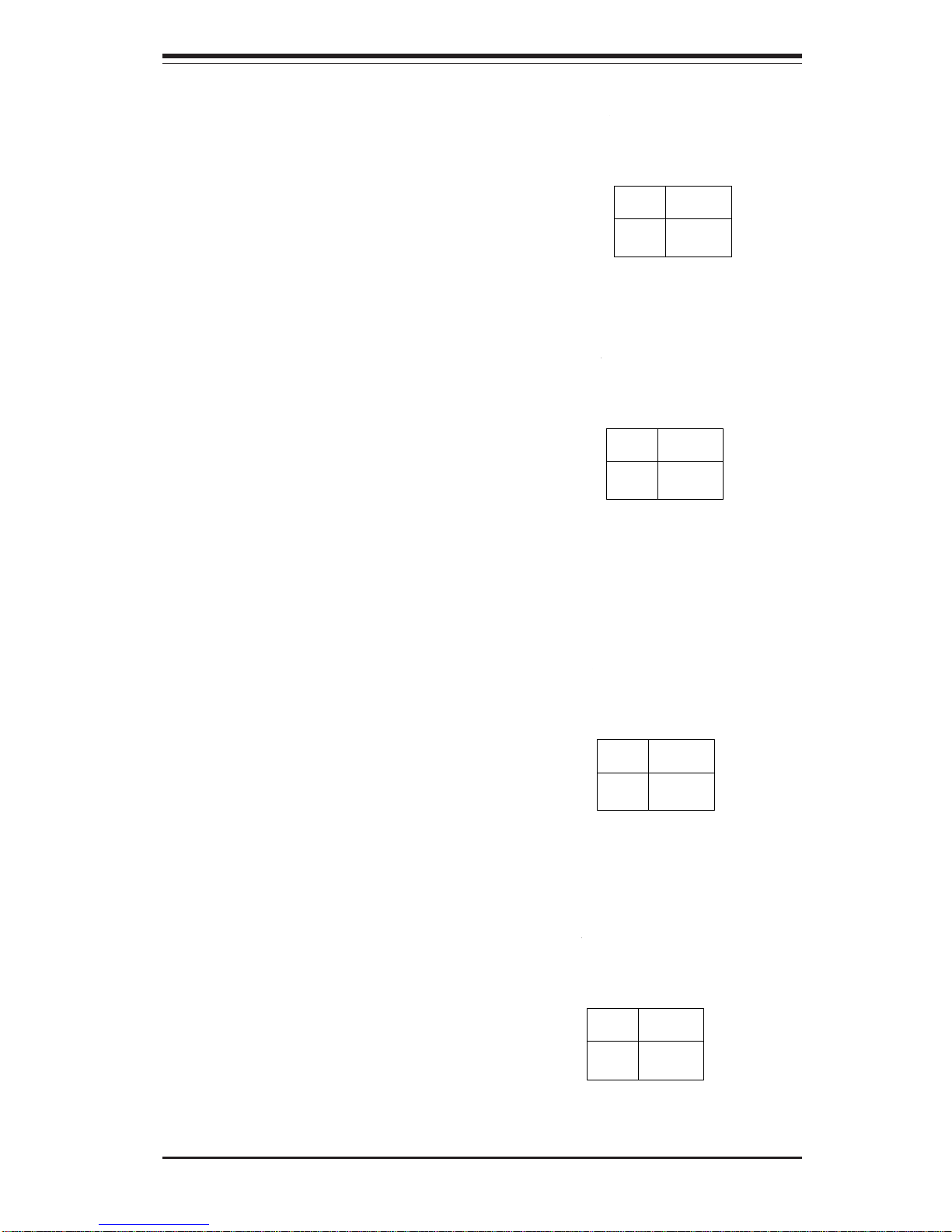
Connect an LED to the OH connection on pins 7 and 8 of JF1 to provide
warning of a processor overheating.
The LED will blink as long as an
overheat condition exists. Refer to
the table on the right for pin definitions.
NIC LEDs
The NIC (Network Interface Controller) LED connections for the GLAN
port1 is located on pins 11 and 12 of
JF1 and the NIC LED connections for
GLAN port 2 are located on pins 9
and 10 of JF1. Attach the NIC1 LED
cable to display network activity.
Refer to the table on the right for pin
definitions.
NIC LED Pin
Definitions
(JF1)
Pin
Number
9/11
10/12
Definition
Vcc
GND
Overheat (OH) LED
Pin Definitions
(JF1)
Pin
Number
7
8
Definition
Vcc
GND
Power Fail LED Pin
Definitions
(JF1)
Pin
Number
5
6
Definition
Vcc
GND
HDD LED
The HDD LED (for IDE and SCSI Disk
Drives) connection is located on pins
13 and 14 of JF1. Attach the hard
drive LED cable to these pins to display disk activity. Refer to the table
on the right for pin definitions.
HDD LED Pin
Definitions
(JF1)
Pin
Number
13
14
Definition
Vcc
HD Active
Power Fail LED
The Power Fail LED connection is
located on pins 5 and 6 of JF1. Refer
to the table on the right for pin definitions.
Page 48
5-14
SUPERWORKSTATION 7044A-82/7044A-8/7044A-i2/7044A-i Manual
Power Button
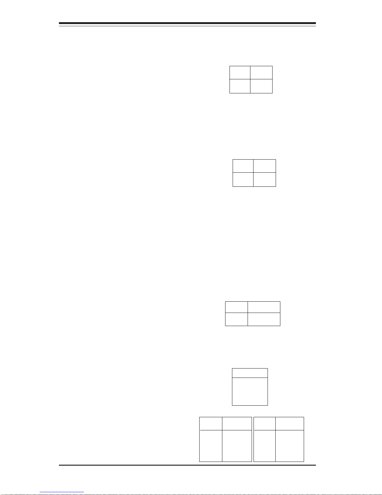
The Power Button connection is located on pins 1 and 2 of JF1. Momentarily contacting both pins will
power on/off the system. This button
can also be configured to function as
a suspend button (see the appropriate setting in BIOS). To turn off the
power when set to suspend mode,
depress the button for at least 4 seconds. Refer to the table on the right
for pin definitions.
Pin
Number
1
2
Definition
PW_ON
Ground
Power Button
Connector
Pin Definitions
(JF1)
Universal Serial Bus
(USB0/1)
There are eight USB 2.0 (Universal
Serial Bus) ports/headers on the
motherboard. Four of them are back
panel USB ports (USB0-3 at J40),
and the other four are front panel
USB headers (USB4/5:JD3 and
USB6/7: JD2). See the tables on the
right for pin definitions.
Reset Button
The Reset Button connection is located on pins 3 and 4 of JF1. Attach
it to the hardware reset switch on the
computer case. Refer to the table on
the right for pin definitions.
Chassis Intrusion
A Chassis Intrusion header is located at JL1. Attach the appropriate cable to inform you of a chassis intrusion.
Pin
Number
3
4
Definition
Reset
Ground
Reset Pin
Definitions
(JF1)
Pin
Number
1
2
Definition
Intrusion Input
Ground
Chassis Intrusion
Pin Definitions (JL1)
Pin# Definition
1 +5V
2 P0-
3 P0+
4 Ground
Pin
Number
2
4
6
8
10
Definition
+5V
PO-
PO+
Ground
Ground
Pin
Number
1
3
5
7
Definition
+5V
POPO+
Ground
USB Pin Definitions
JD2 & JD3 (FP USB)
J40 (Back Panel USB)
Page 49
Chapter 5: Advanced Serverboard Setup
5-15
ATX PS/2 Keyboard and
PS/2 Mouse Ports
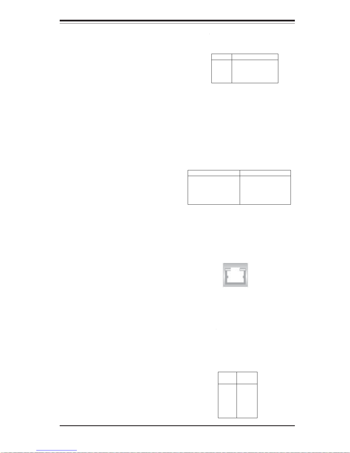
The ATX PS/2 keyboard and PS/2
mouse are located on J9. See the
table at right for pin definitions.
(See Figure 5-3 for the locations of
each.)
PS/2 Keyboard
and Mouse Port
Pin Definitions
(J9)
Pin
Number
1
2
3
4
5
6
Definition
Data
NC
Ground
VCC
Clock
NC
Serial Ports
The COM1 (J3) and COM2 (J4) serial
ports are located under the parallel
port (see Figure 2-3). See the table
on the right for pin definitions.
GLAN1/2 (Ethernet Ports)
Two Gigabit Ethernet ports (designated LAN1 and LAN2) are located
on the I/O backplane. These ports
accept RJF1 type cables.
Note: Pin 10 is included on the header but not on
the port.
Fan Headers
There are eight fan headers (FAN1FAN8) on the X6DA8-G2/X6DAE-G2.
See the table on the right for pin definitions. (Note: These fan headers are
4-pin fans. Pins 1-3 are backward
compatible with traditional 3-pin
fans.)
Fan Header Pin Definitions
Pin #
1
2
3
4
Definition
Ground (black)
+12V (red)
Tachometer
PWR_Control
Caution: These fan headers
use DC power.
Serial Port Pin Definitions
(COM1, COM2)
Pin Number Definition
1 CD
2 RD
3 TD
4 DTR
5 Ground
Pin Number Definition
6 DSR
7 RTS
8 CTS
9 RI
10 NC
Page 50
5-16
SUPERWORKSTATION 7044A-82/7044A-8/7044A-i2/7044A-i Manual
Power LED/Speaker/NMI
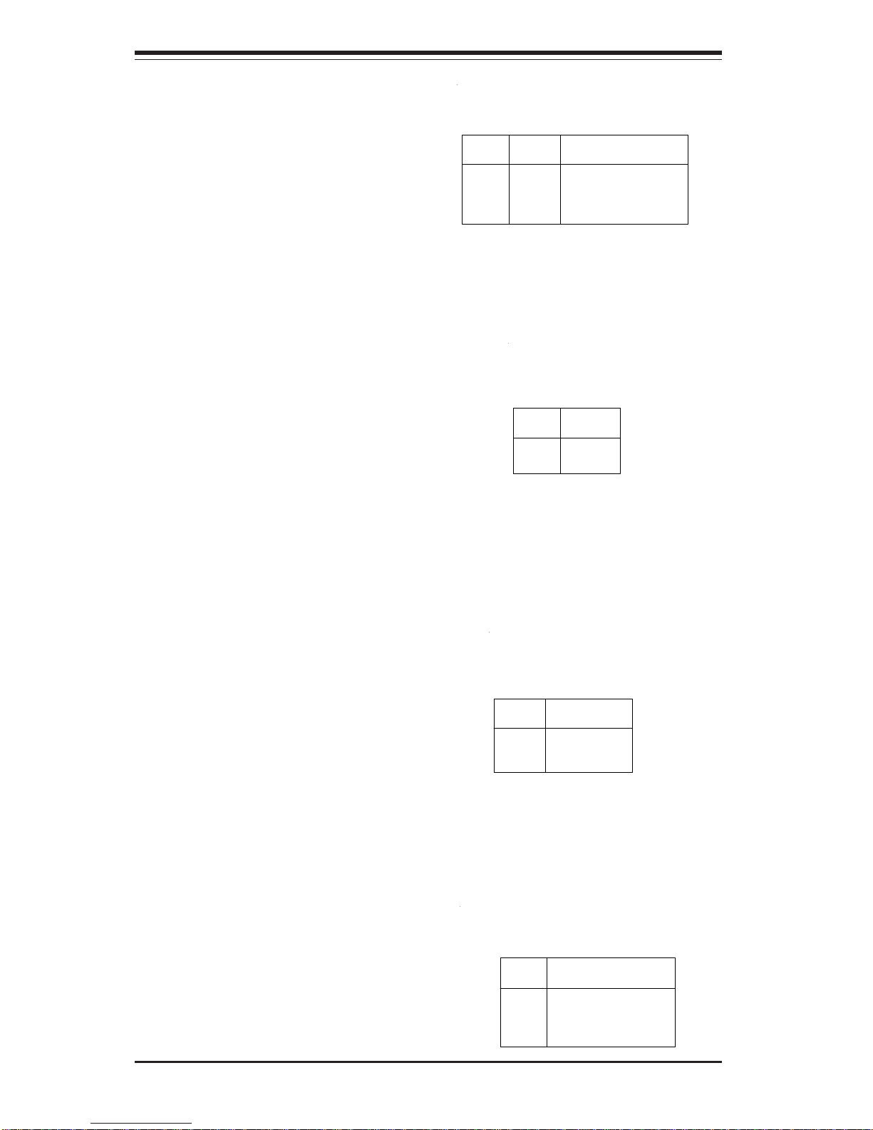
On the JDI header, pins 1-3 are for
a power LED and pins 4-7 are for the
speaker. See the table on the right
for speaker pin definitions.
Note: The speaker connector pins
are for use with an external speaker.
If you wish to use the onboard
speaker, you should close pins 6-7
with a jumper.
Speaker Connector Pin
Definitions (JD1)
Pin
Number
4
5
6
7
Function
+
Key
Definition
Red wire, Speaker data
No connection
Key
Speaker data
Wake-On-Ring
The Wake-On-Ring header is designated JWOR1. This function allows
your computer to receive and "wakeup" by an incoming call to the modem when in suspend state. See
the table on the right for pin definitions. You must have a Wake-OnRing card and cable to use this feature.
Wake-on-Ring
Pin Definitions
(JWOR1)
Pin
Number
1
2
Definition
Ground
Wake-up
Wake-On-LAN
The Wake-On-LAN header is located
at JWOL on the motherboard. See
the table on the right for pin definitions. You must enable the LAN
Wake-Up setting in BIOS to use this
function. (You must also have a LAN
card with a Wake-On-LAN connector
and cable to use this feature.)
Pin
Number
1
2
3
Definition
+5V Standby
Ground
Wake-up
Wake-On-LAN Pin
Definitions (JWOL)
SMB
A System Management Bus header
is located at J22. Connect the appropriate cable here to utilize SMB
on your system.
SMB Header
Pin Definitions (J22)
Pin
Number
1
2
3
4
Definition
Data
Ground
Clock
No Connection
Page 51
Chapter 5: Advanced Serverboard Setup
5-17
Power Fault
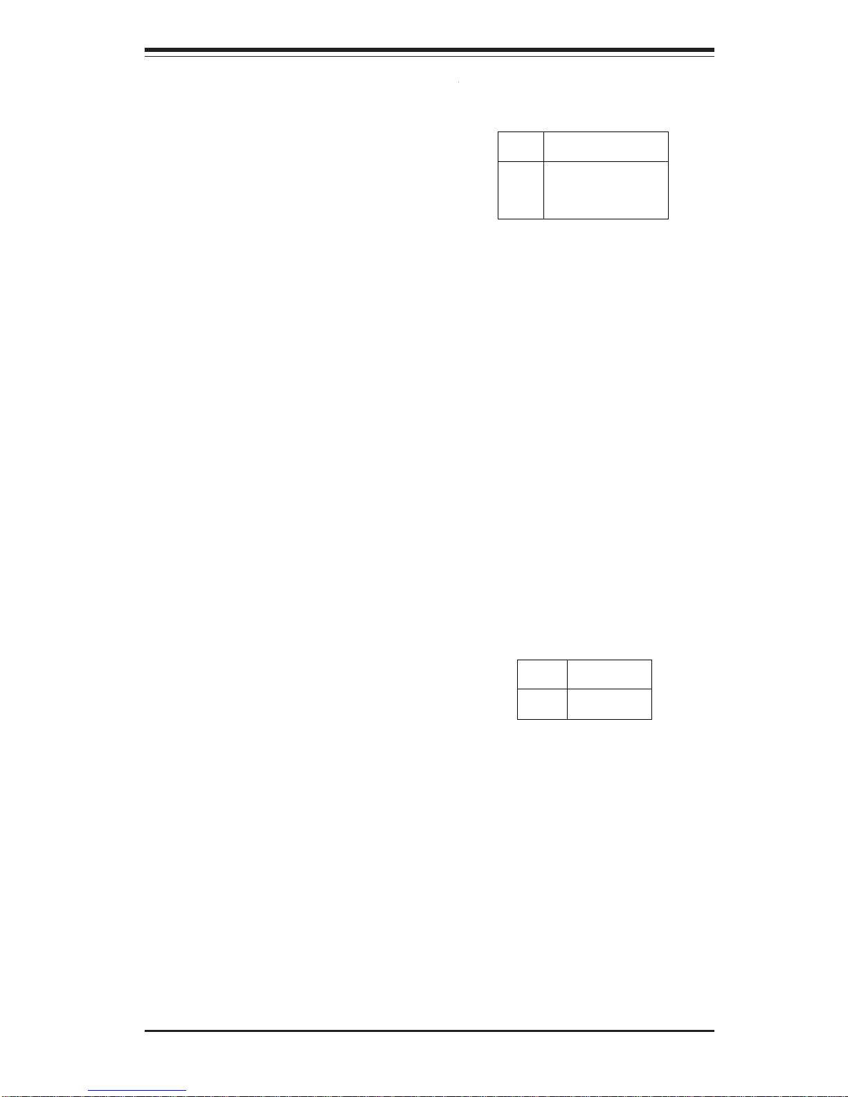
Connect a cable from your power
supply to the Power Fail header
(JP12) to provide warning of power
supply failure. This warning signal is
passed through the PWR_LED pin to
indicate of a power failure on the
chassis. See the table on the right
for pin definitions.
Power Fail
Pin Definitions (JP12)
Pin
Number
1
2
3
4
Definition
P/S 1 Fail Signal
P/S 2 Fail Signal
P/S 3 Fail Signal
Reset (from MB)
Note: This feature is only available when
using redundant Supermicro power supplies.
Keylock
The keyboard lock connection is located on JK1. Utilizing this header
allows you to inhibit any actions made
on the keyboard, effectively "locking"
it.
Power Supply Fail Alarm
Reset
If three power supplies are installed and JP14 is enabled, the
system will notify you if any of the
three power modules fail. Connect jumper JP13 to a microswitch
to enable you to turn off the alarm
that sounds when a power module fails. See the table on the right
for pin definitions.
Pin
Number
2
1
Definition
+5V
Ground
Power Supply Fail
Alarm Reset
Pin Definitions
(JP13)
Page 52
5-18
SUPERWORKSTATION 7044A-82/7044A-8/7044A-i2/7044A-i Manual
5-9 Jumper Settings
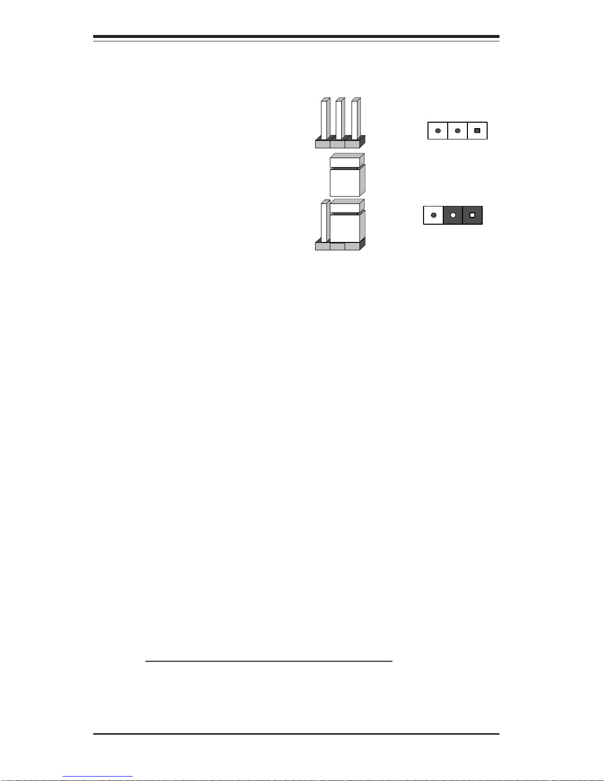
Explanation of
Jumpers
To modify the operation of the
serverboard, jumpers can be
used to choose between
optional settings. Jumpers
create shorts between two pins
to change the function of the
connector. Pin 1 is identified
with a square solder pad on
the printed circuit board. See
the serverboard layout pages
for jumper locations.
Note: On two pin jumpers,
"Closed" means the jumper is on
and "Open" means the jumper is
off the pins.
Connector
Pins
Jumper
Cap
Setting
Pin 1-2 short
3 2 1
3 2 1
CMOS Clear
JBT1 is used to clear CMOS (which will also clear any passwords). Instead of
pins, this jumper consists of contact pads to prevent accidentally clearing the
contents of CMOS.
To clear CMOS,
1) First unplug the power cord(s)
2) With the power disconnected, short the CMOS pads with a metal object such
as a small screwdriver
3) Remove the screwdriver (or shorting device)
4) Reconnect the power cord(s) and power on the system.
Note: Do not use the PW_ON connector to clear CMOS.
Page 53
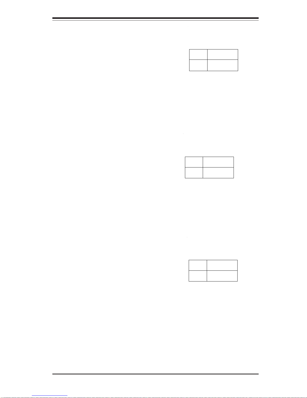
Chapter 5: Advanced Serverboard Setup
5-19
GLAN Enable/Disable
Change the setting of jumper JPL1 to
enable or disable the onboard GLAN
ports (GLAN1 and GLAN2) on the
serverboard. See the table on the
right for jumper settings. The default
setting is enabled
Jumper
Position
Pins 1-2
Pins 2-3
Definition
Enabled
Disabled
GLAN
Enable/Disable
Jumper Settings
(JPL1)
SCSI Controller Enable/
Disable (X6DA8-G2/X6DA8-G
only)
Jumper JPA1 allows you to enable or
disable the SCSI headers. The default setting is pins 1-2 to enable all
four headers. See the table on the
right for jumper settings.
Jumper
Position
Pins 1-2
Pins 2-3
Definition
Enabled
Disabled
SCSI Enable/Disable
Jumper Settings
(JPA1)
SCSI Termination Enable/
Disable (X6DA8-G2/X6DA8-G
only)
Jumpers JPA2 and JPA3 allow you to
enable or disable termination for the
SCSI connectors. Jumper JPA2 controls SCSI channel A and JPA3 is for
channel B. The default setting is open
to enable (terminate) both SCSI channels.
Note: In order for the SCSI drives to
function properly, please do not
change the default setting set by the
manufacturer. See the table on the
right for jumper settings.
Jumper
Position
Open
Closed
Definition
Enabled
Disabled
SCSI Channel Termination
Enable/Disable
Jumper Settings
(JPA2, JPA3)
Page 54
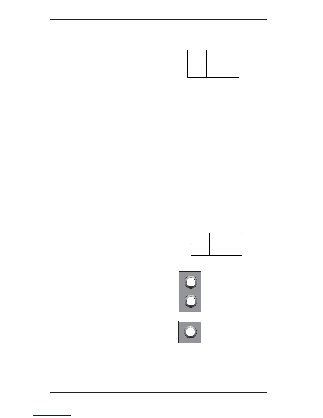
5-20
SUPERWORKSTATION 7044A-82/7044A-8/7044A-i2/7044A-i Manual
Blue: Line In (surround
sound L/R)
Green: Line Out
(front L/R)
Pink: MIC In (center/
subwoofer)
Jumper
Position
1-2
2-3
Definition
Enabled
Disabled
AC97 Enable/Disable
Jumper Settings (JPC1)
AC'97 Audio Enable/Disable
AC'97 provides high quality onboard audio. The serverboard features 6-channel
sound for front L&R, rear L&R, center
and subwoofer speakers. This feature is
activated with the Advanced software on
the CD-ROM included with your
motherboard. The Line In, Line Out and
MIC jacks (see at right) may then be
used. Activate AC 97 with the "AC 97
Audio" setting in the Advanced Chipset
Features section of BIOS. To activate
the Onboard Audio, please enable the
Jumper JPC1. See the table on right for
pin definitions.
Watch Dog Enable/Disable
JWD enables the Watch Dog function. Watch Dog is a system monitor that can reboot the system when
a software application is "hung up".
Pins 1-2 will cause WD to reset the
system if an application is hung up.
Pins 2-3 will generate a nonmaskable interrupt signal for the application that is hung up. See the
table on the right for jumper settings.
Watch Dog can also be enabled via
BIOS.
Note: When enabled, the user needs
to write his own application software
in order to disable the Watch Dog
Timer.
Jumper
Position
Pins 1-2
Pins 2-3
Open
Definition
WD to Reset
WD to NMI
Disabled
Watch Dog
Jumper Settings (JWD)
Page 55
Chapter 5: Advanced Serverboard Setup
5-21
3rd Power Supply Alarm
Enable/Disable
The system can notify you in the
event of a power supply failure. This
feature assumes that three power
supply units are installed in the
chassis with one acting as a
backup. If you only have one or two
power supply units installed, you
should disable this (the default setting) with JP14 to prevent false
alarms. See the table on right for pin
definitions.
Jumper
Position
Open
Closed
Definition
Disabled
Enabled
Power Supply
Alarm Enable/Disable
Jumper Settings (JP14)
Power Force On Enable/
Disable
Jumper JPF allows you to enable or
disable the Power Force On function.
If enabled, the power will always stay
on automatically. If this function disabled, the user needs to press the
power button to power on the system.
Jumper
Position
Open
Closed
Definition
Normal
Force On
Force Power On
(JPF)
Page 56
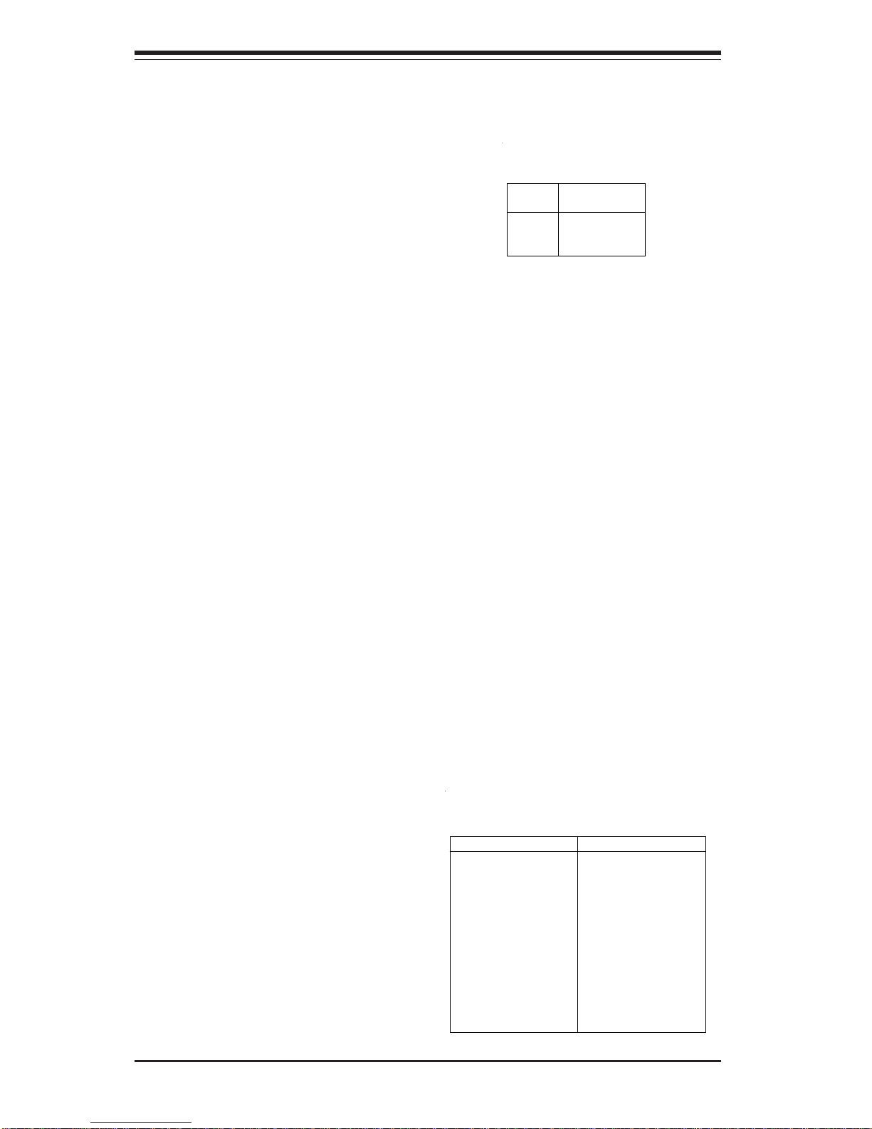
5-22
SUPERWORKSTATION 7044A-82/7044A-8/7044A-i2/7044A-i Manual
5-11 Parallel Port, Floppy/Hard Disk Drive and SCSI
Connections
Note the following when connecting the floppy and hard disk drive cables:
• The floppy disk drive cable has seven twisted wires.
• A red mark on a wire typically designates the location of pin 1.
• A single floppy disk drive ribbon cable has 34 wires and two connectors
to provide for two floppy disk drives. The connector with twisted wires
always connects to drive A, and the connector that does not have
twisted wires always connects to drive B.
Parallel (Printer) Port
Connector
The parallel (printer) port is located
on J23. See the table on the right for
pin definitions.
Pin Number Function
1 Strobe 3 Data Bit 0
5 Data Bit 1
7 Data Bit 2
9 Data Bit 3
11 Data Bit 4
13 Data Bit 5
15 Data Bit 6
17 Data Bit 7
19 ACK
21 BUSY
23 PE
25 SLCT
Pin Number Function
2 Auto Feed 4 Error 6 Init 8 SLCT IN 10 GND
12 GND
14 GND
16 GND
18 GND
20 GND
22 GND
24 GND
26 NC
Parallel ( P rinter) Port Pin Definitions
(J23)
5-10 Onboard Indicators
GLAN1/GLAN2 LEDs
Each of the Ethernet ports (located
beside the VGA port) have two
LEDs. The yellow LED indicates
activity while the other LED may be
green, orange or off to indicate
the speed of the connection. See
the table on the right for the functions associated with this second
LED.
LED
Color
Off
Green
Orange
Definition
No Connection
100 MHz
1 GHz
1 Gb LAN Right LED
Indicator
Page 57
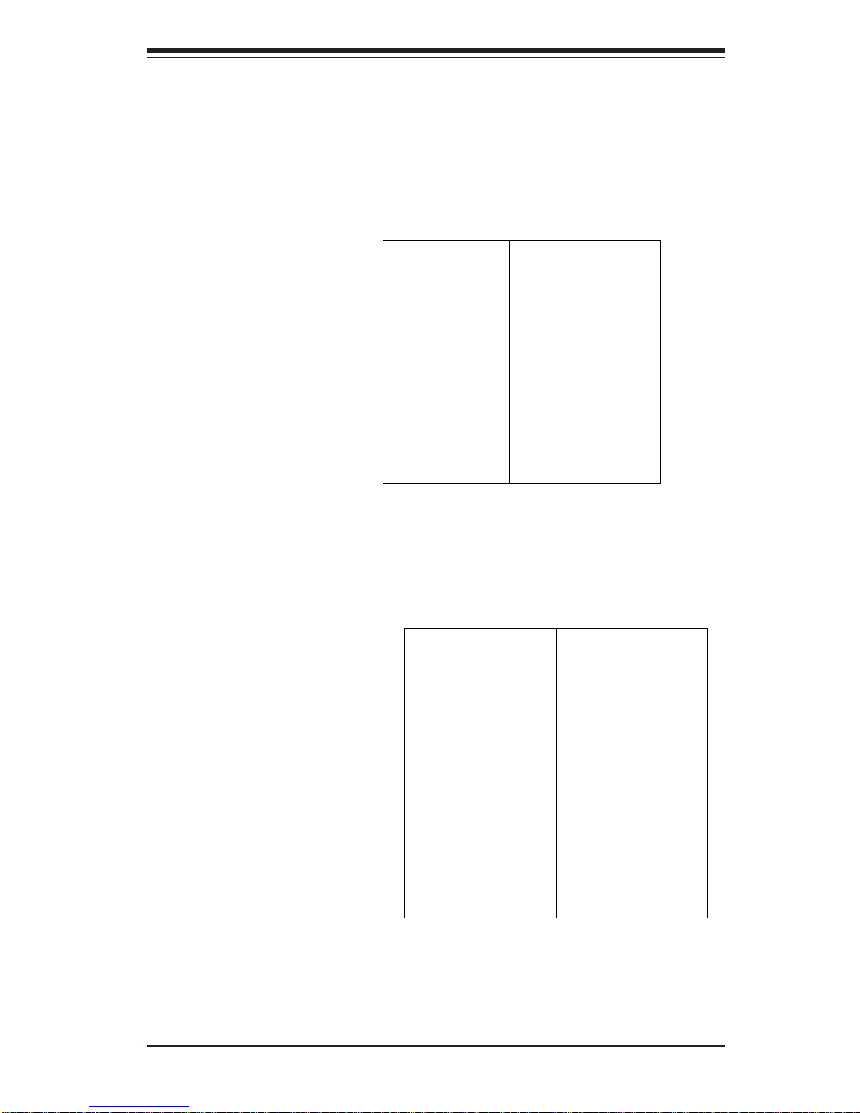
Chapter 5: Advanced Serverboard Setup
5-23
IDE Connectors
There are no jumpers to
configure the onboard IDE#1
and #2 connectors. See the
table on the right for pin
definitions.
Pin Number Function
1 GND
3 GND
5 Key
7 GND
9 GND
11 GND
13 GND
15 GND
17 GND
19 GND
21 GND
23 GND
25 GND
27 GND
29 GND
31 GND
33 GND
Pin Number Function
2 FDHDIN
4 Reserved
6 FDEDIN
8 Index 10 Motor Enable
12 Drive Select B 14 Drive Select A 16 Motor Enable
18 DIR 20 STEP 22 Write Data 24 Write Gate 26 Track 00 28 Write Protect 30 Read Data 32 Side 1 Select 34 Diskette
Floppy Connector Pin Definitions (JP8)
Pin Number F unction
1 Reset IDE
3 Host Data 7
5 Host Data 6
7 Host Data 5
9 Host Data 4
11 Host Data 3
13 Host Data 2
15 Host Data 1
17 Host Data 0
19 GND
21 DRQ3
23 I/O Write 25 I/O Read 27 IOCHRDY
29 DACK3 31 IRQ14
33 Addr 1
35 Addr 0
37 Chip Select 0
39 Activity
Pin Number Function
2 GND
4 Host Data 8
6 Host Data 9
8 Host Data 10
10 Host Data 11
12 Host Data 12
14 Host Data 13
16 Host Data 14
18 Host Data 15
20 Key
22 GND
24 GND
26 GND
28 BALE
30 GND
32 IOCS16 34 GND
36 Addr 2
38 Chip Select 1 40 GND
IDE Connecto r Pin Definitions
(J3, J4)
Floppy Connector
The floppy connector is located on
JP8. See the table below for pin
definitions.
Page 58
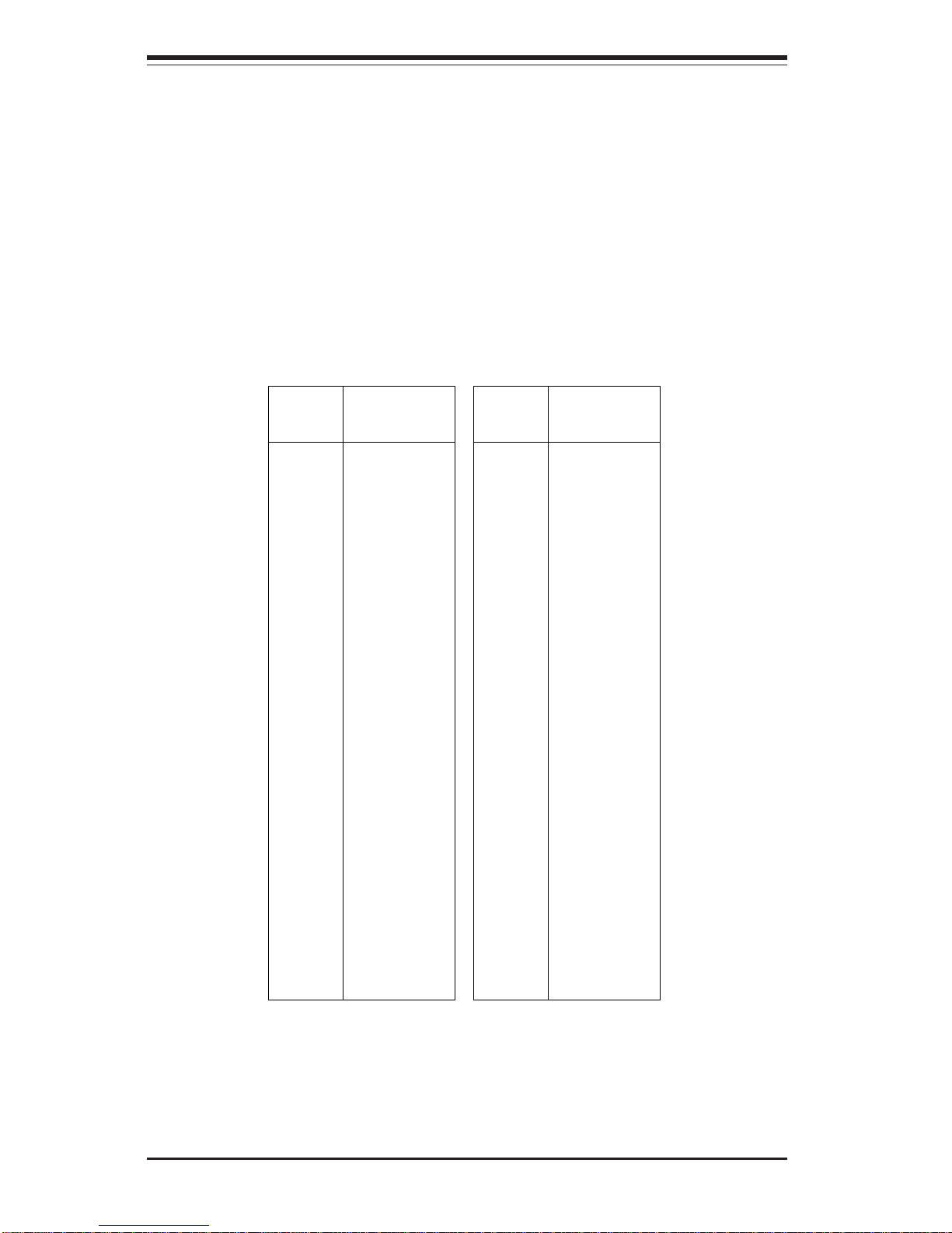
5-24
SUPERWORKSTATION 7044A-82/7044A-8/7044A-i2/7044A-i Manual
Signal Names
+DB(12)
+DB(13)
+DB(14)
+DB(15)
+DB(P1)
+DB(0)
+DB(1)
+DB(2)
+DB(3)
+DB(4)
+DB(5)
+DB(6)
+DB(7)
+DB(P)
GROUND
DIFFSENS
TERMPWR
TERMPWR
RESERVED
GROUND
+ATN
GROUND
+BSY
+ACK
+RST
+MSG
+SEL
+C/D
+REQ
+I/O
+DB(8)
+DB(9)
+DB(10)
+DB(11)
Connector
Contact
Number
1
2
3
4
5
6
7
8
9
10
11
12
13
14
15
16
17
18
19
20
21
22
23
24
25
26
27
28
29
30
31
32
33
34
Signal Names
-DB(12)
-DB(13)
-DB(14)
-DB(15)
-DB(P1)
-DB(0)
-DB(1)
-DB(2)
-DB(3)
-DB(4)
-DB(5)
-DB(6)
-DB(7)
-DB(P)
GROUND
GROUND
TERMPWR
TERMPWR
RESERVED
GROUND
-ATN
GROUND
-BSY
-ACK
-RST
-MSG
-SEL
-C/D
-REQ
-I/O
-DB(8)
-DB(9)
-DB(10)
-DB(11)
Connector
Contact
Number
35
36
37
38
39
40
41
42
43
44
45
46
47
48
49
50
51
52
53
54
55
56
57
58
59
60
61
62
63
64
65
66
67
68
Ultra320 SCSI Connectors (JA1, JA2)
Ultra320 SCSI Connectors
(X6DA8-G2/X6DA8-G only)
Refer to the table below for the pin definitions of the Ultra320 SCSI connectors located at JA1 and JA2.
Page 59

Chapter 6: Advanced Chassis Setup
6-1
Chapter 6
Advanced Chassis Setup
This chapter covers the steps required to install components and perform simple
maintenance on the SC743S1-645/SC743i-645 chassis. Following the component installation steps in the order given will eliminate most common problems.
If some steps are unnecessary, skip ahead to the step that follows. Refer to
Chapter 2 for instructions on installing the system as a 4U rackmount.
Tools Required
The only tool you will need is a Philips screwdriver.
6-1 Static-Sensitive Devices
Static electrical discharge can damage electronic components. To prevent
damage to any printed circuit boards (PCBs), it is important to handle them
very carefully. The following measures are generally sufficient to protect your
equipment from static discharge.
Precautions
• Use a grounded wrist strap designed to prevent static discharge.
• Touch a grounded metal object before removing any board from its antistatic bag.
• Handle a board by its edges only; do not touch its components, peripheral
chips, memory modules or gold contacts.
• When handling chips or modules, avoid touching their pins.
• Put the serverboard, add-on cards and peripherals back into their antistatic bags when not in use.
• For grounding purposes, make sure your computer chassis provides excellent conductivity between the power supply, the case, the mounting
fasteners and the serverboard.
Unpacking
The serverboard is shipped in antistatic packaging. When unpacking the
board, make sure the person handling it is static protected.
Page 60
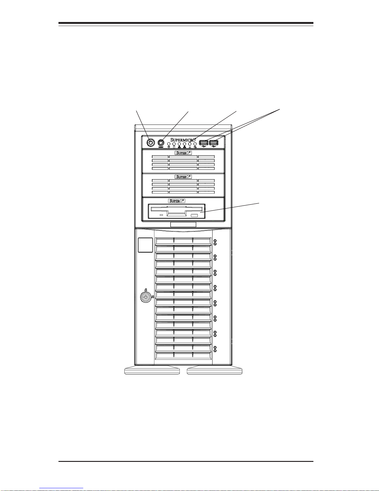
6-2
SUPERWORKSTATION 7044A-82/7044A-8/7044A-i2/7044A-i Manual
8 SCSI Drive Bays (7044A82/7044A-8 only)
Figure 6-1. Chassis Front View
System ResetMain Power
System LEDs
Floppy Drive
5.25" Drive Bays (2)
USB Ports
2 IDE Drive Carriers, 4
hard drives each (7044Ai2/7044A-i only)
Page 61
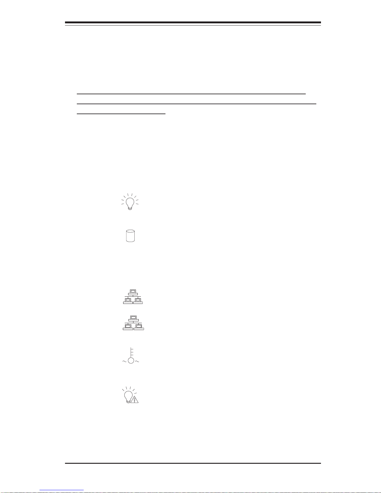
Chapter 6: Advanced Chassis Setup
6-3
6-2 Front Control Panel
The front control panel must be connected to the JF1 connector on the
serverboard to provide you with system status and alarm indications. A
ribbon cable has bundled these wires together to simplify this connection.
Connect the cable from JF1 on the serverboard (making sure the red wire
plugs into pin 1) to the appropriate comnnector on the front control panel
PCB (printed circuit board). Pull all excess cabling over to the control
panel side of the chassis. The LEDs on the control panel inform you of
system status - see Figure 6-2 for details. See Chapter 5 for details on JF1.
Figure 6-2. Front Control Panel LEDs
Power
NIC
HDD
Power Fail
Overheat
Indicates power is being supplied to the system.
Indicates network activity on GLAN port 1.
Indicates IDE device and hard drive activity. On the
7044A-82/7044A-8, this LED indicates SCSI hard drive
activity when flashing. On the 7044A-i2/7044A-i, this
LED indicates IDE hard drive activity when flashing.
Non-applicable (for redundant power supply systems
only).
When this LED flashes, it indicates a fan failure. When
on continuously it indicates an overheat condition (see
Chapter 3 for details).
NIC
Indicates network activity on GLAN port 2 (7044A-82/
7044A-i2 only).
Page 62

6-4
SUPERWORKSTATION 7044A-82/7044A-8/7044A-i2/7044A-i Manual
6-3 System Fans
Four 8-cm chassis cooling fans (located in the center of the chassis) provide
cooling airflow. The chassis is fitted with an air shroud to concentrate the flow
of cooling air over the areas of highest generated heat. The fans should all be
connected to headers on the serverboard (see Chapter 5). The power supply
module also has a cooling fan.
Fan Failure
Under normal operation, all four chassis fans and the power supply fan run
continuously. The four chassis cooling fans (not the power supply fan) are hotswappable and can be replaced without powering down the system.
Replacing System Fans
1. Identifying the failed fan:
To locate and replace a failed chassis fan, begin by removing the top/left
chassis cover (see Chapter 2 for details on removing the cover).
2. Removing a hot-plug fan housing:
Depress the locking tab on a chassis cooling fan and pull the unit straight
out by the handle (see Figure 6-3). The fan wiring for these fans has been
designed to detach automatically.
3. Installing a new system fan:
Replace the failed fan with an identical one (available from Supermicro).
Install and reassemble it in the fan housing then plug the housing back
into its slot; it should click into place when fully inserted. Check that the fan
is working properly and replace the top/left side chassis panel.
Removing the air shroud:
Under most circumstances you will not need to remove the air shroud to
perform any service on the system. However, if you wish to temporarily
remove it (the air shroud sould always be in place when the system is
operating), please follow this procedure. Begin by depressing the tabs at the
front and rear of the shroud to unlock it, then lift it up and out of the chassis
(see Figure 6-4). To reinstall, simply position the air shroud in its proper
place and push it in until you hear it click.
Page 63
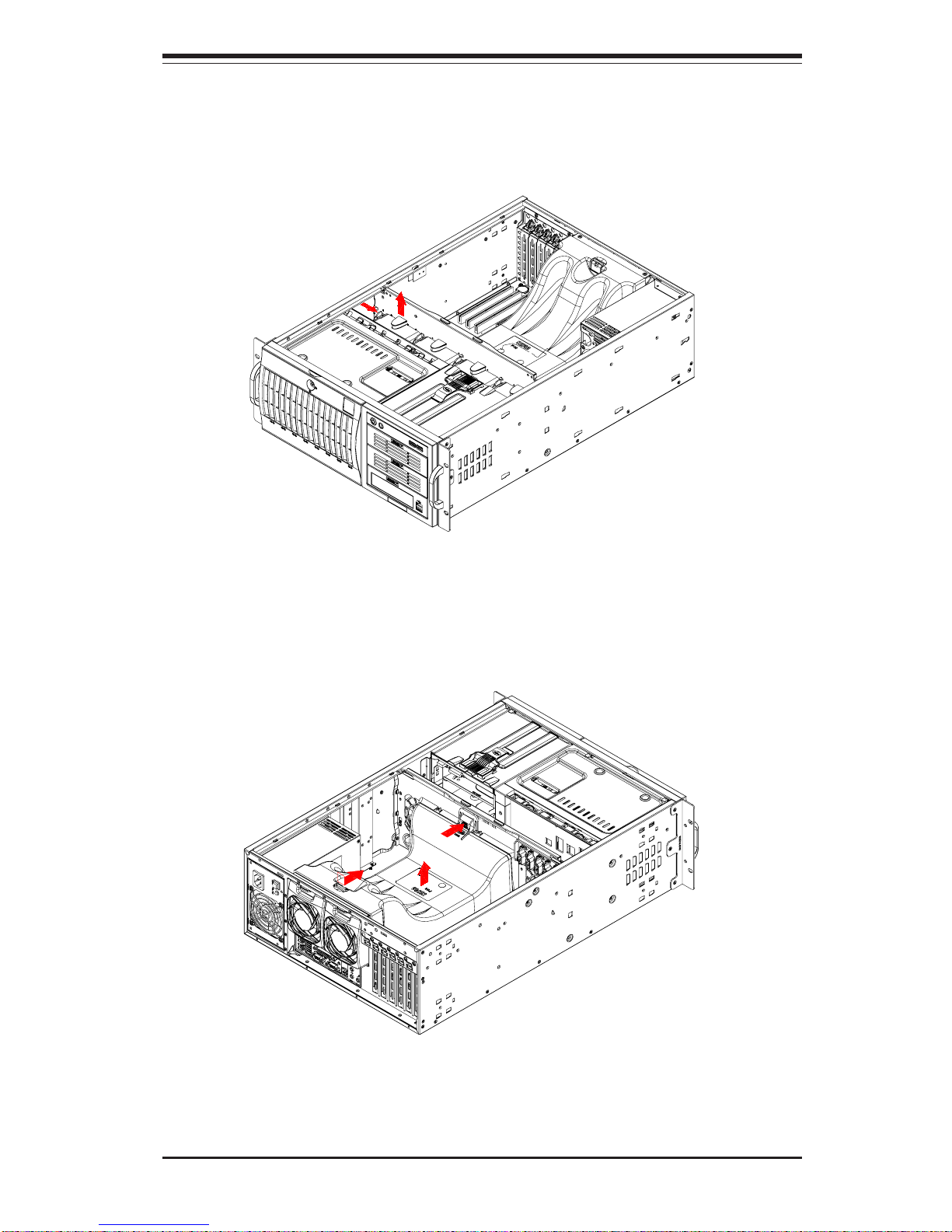
Chapter 6: Advanced Chassis Setup
6-5
Figure 6-4. Removing the Air Shroud
Figure 6-3. Removing a Chassis Fan
Page 64
6-6
SUPERWORKSTATION 7044A-82/7044A-8/7044A-i2/7044A-i Manual
1. Installing/removing hot-plug SCSI drives:
The eight SCSI drive carriers are all easily accessible at the front of the
chassis. The SCSI drives are hot-pluggable, meaning they can be removed
and installed without powering down the system. To remove a carrier, first
push the release button located beside the drive LEDs. Swing the colored
handle fully out and use it to pull the unit straight out (see Figure 6-5).
Note: Your operating system must have RAID support to enable the hot-plug
capability of the SCSI drives.
2. Mounting a SCSI drive in a drive carrier:
The SCSI drives are mounted in drive carriers to simplify their installation
and removal from the chassis. These carriers also work to promote
proper airflow for the system. For this reason, even carriers without
SCSI drives must remain in the server. If you need to add a new SCSI
drive, insert the drive into the carrier with the printed circuit board side
facing down so that the mounting holes align with those in the carrier.
Secure the drive to the carrier with four screws. (See Figure 6-6.)
6-4 Drive Bay Installation
SCSI Drives (7044A-82/7044A-8 only)
Eight SCSI drives may be housed in the SC743S1-645chassis. The SCSI
drive IDs are preconfigured as 0 through 7 in order from right to left (or from
bottom to top if rackmounted).
Note: You must use standard 1" high, 80-pin SCA SCSI drives in the
SuperWorkstation 7044A-82/7044A-8.
Use extreme caution when working around the SCSI backplane.
Do not touch the backplane with any metal objects and make
sure no ribbon cables touch the backplane or obstruct the airflow.
!
Page 65
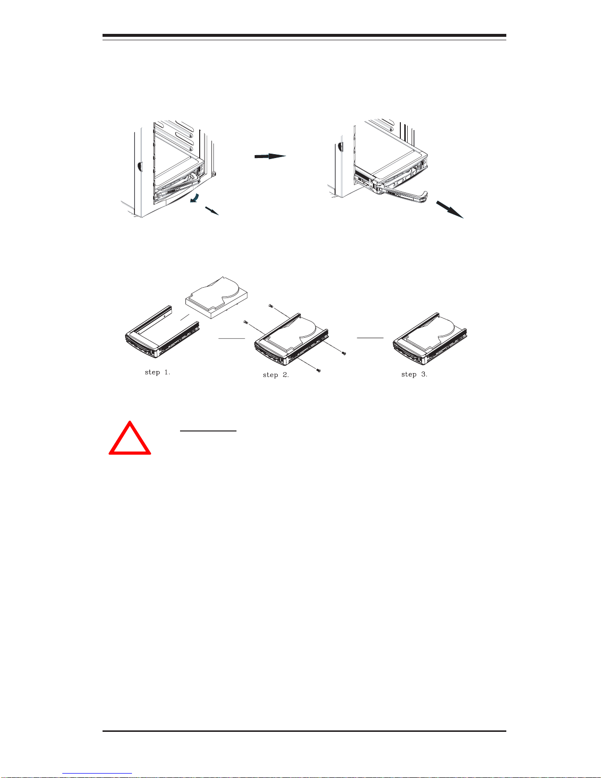
Chapter 6: Advanced Chassis Setup
6-7
Figure 6-6. Mounting a SCSI Drive in a Carrier
!
Important: Regardless of how many SCSI hard drives
are installed, all SCSI drive carriers must remain in the
drive bays to promote proper airflow.
Figure 6-5. Removing a SCSI Drive Carrier
3. SCSI backplane:
All eight SCSI drives plug into a single SCSI backplane, which provides
Ultra320 single channel operation for all eight SCSI drives. A ribbon cable
from JA1 on the serverboard should be connected to the IN connector on the
SCSI backplane. There is also a power connector on the backplane that
must be connected. See Figure 6-7 for the locations of backplane connectors - the reverse side of the backplane has five connectors that the SCSI
drives plug into when inserted with a SCSI drive carrier or mobile rack.
Page 66
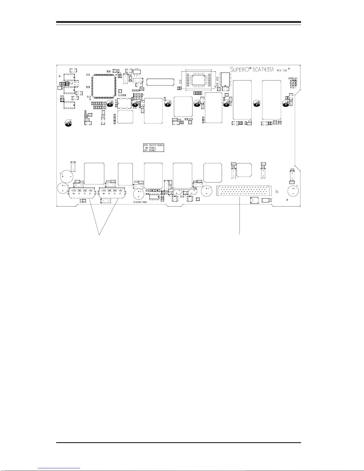
6-8
SUPERWORKSTATION 7044A-82/7044A-8/7044A-i2/7044A-i Manual
Figure 6-7. SCSI Backplane
Jumper Settings
JP19: Buzzer Enable, Closed (On) Enabled (default), Open (Off): Disabled
LEDs
Drive Fail LEDs: Fail1, Fail2, Fail3, Fail4, Fail5, Fail6, Fail7, Fail8
Activity LEDs: ACT1, ACT2, ACT3, ACT4, ACT5, ACT6, ACT7, ACT8
Power Connector
SCSI LVD Connector
Page 67
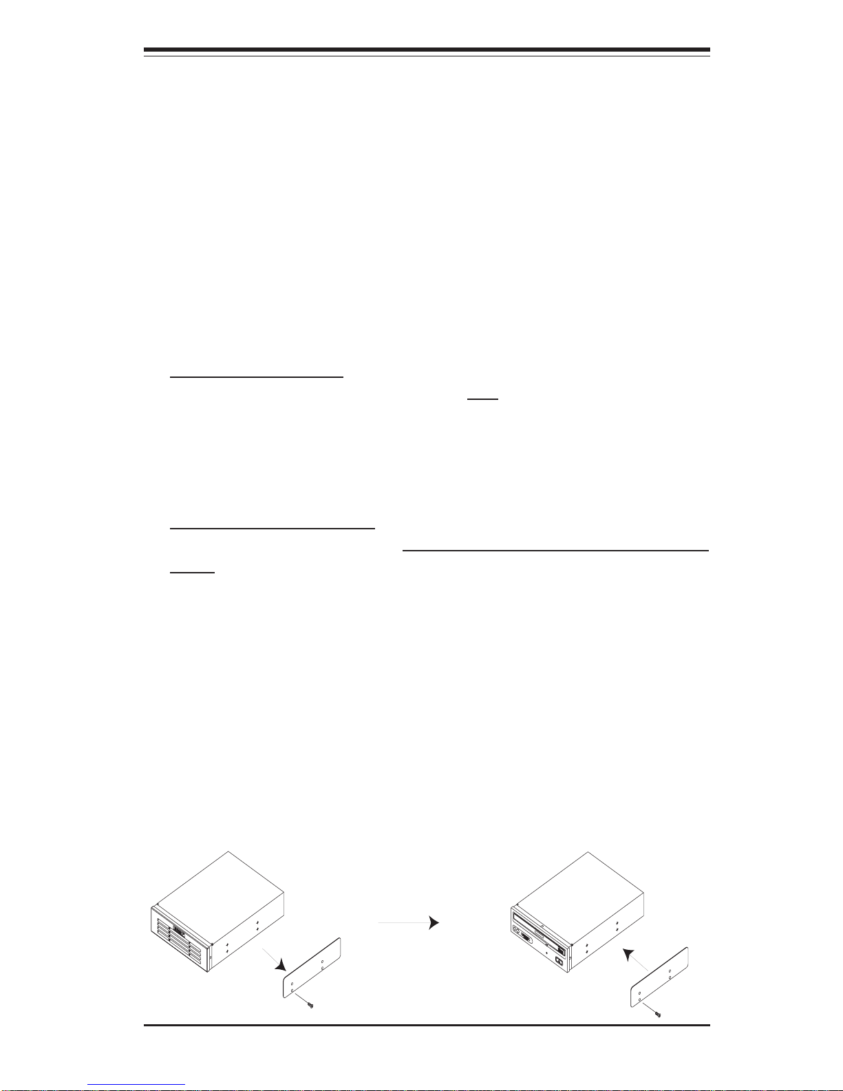
Chapter 6: Advanced Chassis Setup
6-9
Installing Components in the 5.25" Drive Bays
1. Drive bay configuration
The 7044A-82/7044A-i2 has two 5.25" drive bays. Components such as an
extra floppy drive, IDE hard drives or CD-ROM drives can be installed in these
5.25" drive bays.
2. Mounting components in the drive bays
First power down the system and then remove the top/left chassis cover
to access the drive components. With the cover off, remove the two or
four screws that secure the drive carrier to the chassis (one side only)
then push the entire empty drive carrier out from the back.
Adding a CD-ROM drive: remove the guide plate from right side of the
empty drive carrier and screw it into the right side of the CD-ROM drive
using the holes provided (see Figure 6-8). Then slide the CD-ROM into the
bay and secure it to the chassis with the drive carrier screws you first
removed. Attach the power and data cables to the drive. Replace the top/left
chassis cover before restoring power to the system.
Adding an IDE or floppy drive: to add one of these drives, install it into one of
the removed empty drive carriers with the printed circuit board side toward the
carrier so that the drive's mounting holes align with those in the carrier.
Secure the drive to the carrier with four screws then slide the assembly into
the bay and secure it to the chassis with the drive carrier screws you first
removed. Attach the power and data cables to the drive. Replace the top/left
chassis cover before restoring power to the system.
Note: A red wire typically designates the location of pin 1. You should keep
the drive carriers inserted in any unused drive bays to reduce EMI and noise
and to facilitate the airflow inside the chassis.
Figure 6-8. Adding a Component Without a Drive Carrier
Page 68

6-10
SUPERWORKSTATION 7044A-82/7044A-8/7044A-i2/7044A-i Manual
6-5 Power Supply
The SuperWorkstation 7044A-82/7044A-8/7044A-i2/7044A-i has a single 645
watt power supply. This power unit is equipped with low-noise technology,
making the system ideal for workstation environments.
The power supply has an auto-switching capability that enable it to automatically sense and operate with 100 or 240 volt inputs. The power module is
PFC (Power Factor Correction) compliant.
Power Supply Failure
If the power supply unit fails, the system will shut down and you will need to
replace the unit. Replacement units can be ordered directly from Supermicro
(see contact information in the Preface). As there is only one power supply
unit in the 7044A-82/7044A-8/7044A-i2/7044A-i, power must be completely
removed from the server before removing and replacing the power supply unit
for whatever reason.
Replacing the Power Supply
1. Accessing the power supply:
For safety reasons, you will need to remove power from the system when
replacing the power supply on the 7044A-82/7044A-8/7044A-i2/7044A-i. The
power supply can be removed from the back of the chassis; access to the
inside is unnecessary.
2. Removing the power supply:
First, unplug the power cord from the failed power supply. Then press the
locking tab on the module and pull the unit completely out.
3. Installing a new power supply module:
Replace the failed unit with another unit of the same input voltage, output
voltage and wattage. It is highly recommended to replace it with exactly the
same model power supply (PWS-0060). Gently but firmly push the new unit
all the way into the open bay. Secure it to the chassis using the locking
tab. Plug the power cord back into the new power supply. Finish by
depressing the power button on the chassis front control panel.
Page 69

Chapter 7: BIOS
7-1
Chapter 7
BIOS
7-1 Introduction
This chapter describes the Phoenix BIOS™ Setup utility for the X6DA8-G2/
X6DA8-G/X6DAE-G2/X6DAE-G. The Phoenix ROM BIOS is stored in a flash chip
and can be easily upgraded using a floppy disk-based program.
Note: Due to periodic changes to the BIOS, some settings may have been added
or deleted and might not yet be recorded in this manual. Please refer to the
Manual Download area of the Supermicro web site (http://www.supermicro.com)
for any changes to the BIOS that may not be reflected in this manual.
System BIOS
The BIOS is the Basic Input Output System used in all IBM® PC, XT™, AT®, and
PS/2® compatible computers. The Phoenix BIOS flash chip stores the system
parameters, such type of disk drives, video displays, etc. in the CMOS. The
CMOS memory requires very little electrical power. When the computer is turned
off, a back-up battery provides power to the BIOS flash chip, enabling it to retain
system parameters. Each time the computer is powered-on the computer is
configured with the values stored in the BIOS ROM by the system BIOS, which
gains control at boot-up.
How To Change the Configuration Data
The CMOS information that determines the system parameters may be changed
by entering the BIOS Setup utility. This Setup utility can be accessed by pressing the <Delete> key at the appropriate time during system boot, see below.
Starting the Setup Utility
Normally, the only visible POST (Power On Self Test) routine is the memory test.
As the memory is being tested, press the <Delete> key to enter the main menu
of the BIOS Setup utility. From the main menu, you can access the other setup
screens, such as the Security and Power menus. Beginning with Section 7-3,
detailed descriptions are given for each parameter setting in the Setup utility.
Page 70

7-2
SUPERWORKSTATION 7044A-82/7044A-8/7044A-i2/7044A-i Manual
7-2 Running Setup
*Default settings are in bold text unless otherwise noted.
The BIOS setup options described in this section are selected by choosing
the appropriate text from the main BIOS Setup screen. All displayed text is
described in this section, although the screen display is often all you need to
understand how to set the options (see on next page).
When you first power on the computer, the Phoenix BIOS™ is immediately
activated.
While the BIOS is in control, the Setup program can be activated in one of two
ways:
1. By pressing <Delete> immediately after turning the system on, or
2. When the message shown below appears briefly at the bottom of the
screen during the POST (Power On Self-Test), press the <Delete> key to
activate the main Setup menu:
Press the <Delete> key to enter Setup
7-3 Main BIOS Setup
All main Setup options are described in this section. The main BIOS Setup screen
is displayed below.
Use the Up/Down arrow keys to move among the different settings in each menu.
Use the Left/Right arrow keys to change the options for each setting.
Press the <Esc> key to exit the CMOS Setup Menu. The next section describes
in detail how to navigate through the menus.
Items that use submenus are indicated with the icon. With the item highlighted,
press the <Enter> key to access the submenu.
Page 71
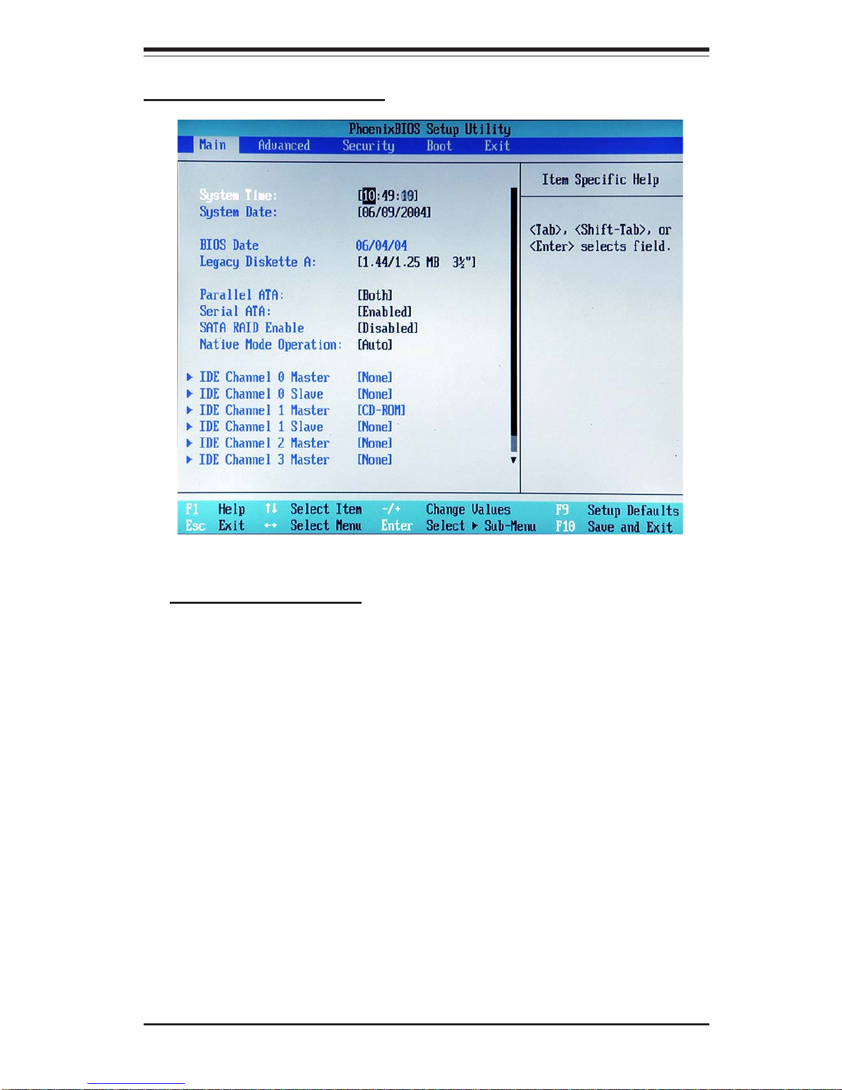
Chapter 7: BIOS
7-3
Main BIOS Setup Menu
Main Setup Features
System Time
To set the system date and time, key in the correct information in the
appropriate fields. Then press the <Enter> key to save the data.
System Date
Using the arrow keys, highlight the month, day and year fields and enter
the correct data. Press the <Enter> key to save the data.
BIOS Date
This feature allows the BIOS to automatically display the BIOS date.
Page 72

7-4
SUPERWORKSTATION 7044A-82/7044A-8/7044A-i2/7044A-i Manual
IDE Channel 0 Master/Slave, IDE Channel 1 Master/Slave, IDE
Channel 2 Master, IDE Channel 3 Master
These settings allow the user to set the parameters of IDE Channel 0
Master/Slave, IDE Channel 1 Master/Slave, IDE Channel 2 Master, IDE
Channel 3 Master slots. Hit <Enter> to activate the following sub-menu
screen for detailed options of these items. Set the correct configurations
accordingly. The items included in the sub-menu are:
Legacy Diskette A
This setting allows the user to set the type of floppy disk drive installed as
diskette A. The options are Disabled, 360Kb 5.25 in, 1.2MB 5.25 in, 720Kb
3.5 in, 1.44/1.25MB, 3.5 in and 2.88MB 3.5 in.
Parallel ATA
This setting allows the user to enable or disable the funciton of Parallel
ATA. The options are Disabled, Channel 0, Channel 1 and Both.
Serial ATA
This setting allows the user to enable or disable the funciton of Serial ATA.
The options are Disabled and Enabled.
Serial ATA RAID Enable
Select Enable to enable Serial ATA RAID Functions. (*For the Windows OS
environment, use the RAID driver if this feature is set to Enabled. If
Disabled, use the "Non-RAID" driver.)
Native Mode Operation
This option allows the user to select the Native Mode for ATA. Some
Operating Systems are not supported by the Native Mode. The options are:
Serial ATA, Parallel ATA, Auto, and Both.
Page 73
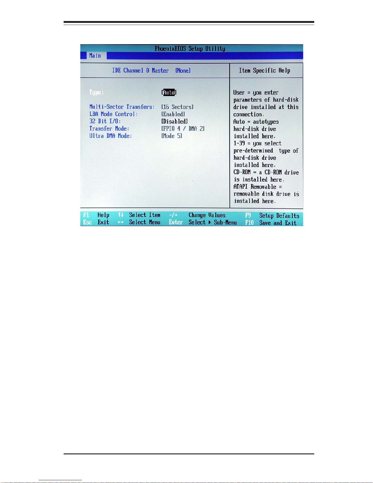
Chapter 7: BIOS
7-5
Type
Selects the type of IDE hard drive. The options are Auto (allows the
BIOS to automatically determine the hard drive's capacity, number of
heads, etc.), a number from 1-39 to select a predetermined type of hard
drive, CD-ROM and ATAPI Removable. The option- "User" will allow the
user to enter the parameters of the HDD installed at this connection. The
option-"Auto" will allow the BIOS to automatically configure the
parameters of the HDD installed at the connection. Choose the option"139" to select a pre-determined HDD type. Select CD-ROM if a CD-ROM
drive is installed. Select ATAPI if a removable disk drive is installed.
Multi-Sector Transfers
Select the number of transfer sectors. The options are Disabled, 2, 4, 6,
8 and 16 Sectors.
Page 74

7-6
SUPERWORKSTATION 7044A-82/7044A-8/7044A-i2/7044A-i Manual
LBA Mode Control
This item determines whether The Phoenix BIOS will access the
IDEChannel 0 Master Device via the LBA mode. The options are Disabled
and Enabled.
32 Bit I/O
This option allows the user to enable or disable the function of 32-bit
datea transfer. The options are Enabled and Disabled.
Transfer Mode
Selects the transfer mode. The options are Standard, Fast PIO1, Fast
PIO2, Fast PIO3, Fast PIO4, FPIO3/DMA1 and FPIO4/DMA2.
Ultra DMA Mode
Selects Ultra DM A Mode. The options are Disabled, Mode 0, Mode 1,
Mode 2, Mode 3, Mode 4 and Mode 5.
System Memory
This display informs you how much system memory is recognized as being
present in the system.
Extended Memory
This display informs you how much extended memory is recognized as
being present in the system.
Page 75
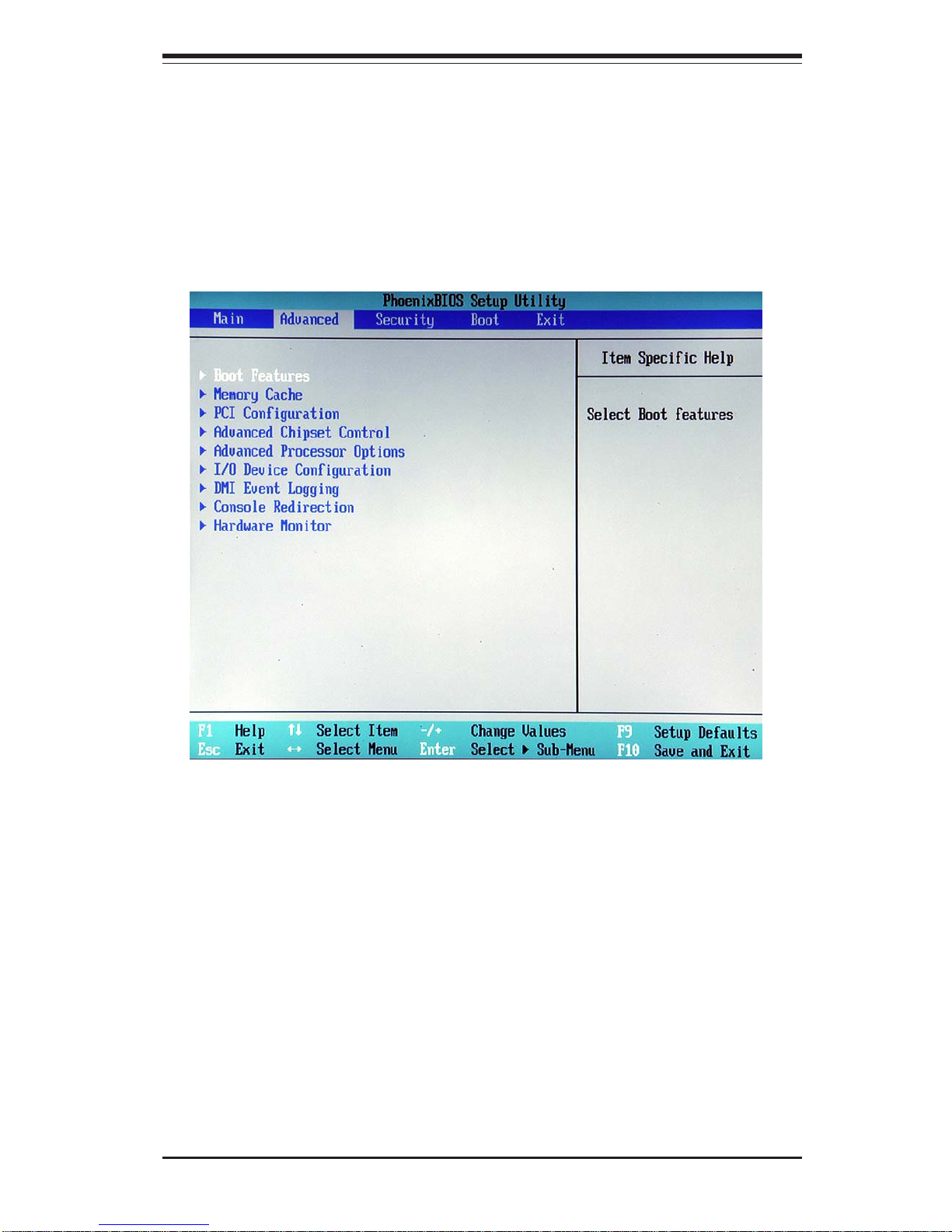
Chapter 7: BIOS
7-7
7-4 Advanced Setup
Choose Advanced from the Phoenix BIOS Setup Utility main menu with the arrow
keys. You should see the following display. The items with a triangle beside them
have sub menus that can be accessed by highlighting the item and pressing
<Enter>. Options for PIR settings are displayed by highlighting the setting option
using the arrow keys and pressing <Enter>. All Advanced BIOS Setup options are
described in this section.
Boot Features
Access the submenu to make changes to the following settings.
Quick Boot Mode
If enabled, this feature will speed up the POST (Power On Self Test)
routine by skipping certain tests after the computer is turned on. The
settings are Enabled and Disabled. If Disabled, the POST routine will run
at normal speed.
Quiet Boot
This setting allows you to Enable or Disable the diagnostic screen during
boot-up.
Page 76

7-8
SUPERWORKSTATION 7044A-82/7044A-8/7044A-i2/7044A-i Manual
ACPI Mode
Use the setting to determine if you want to employ ACPI (Advanced
Configuration and Power Interface) power management on your system.
The options are Yes and No.
ACPI Sleep Mode
Selects the sleep mode for ACPI. The options are S1(-Stanby) and S3
(-Suspend to RAM).
Power Loss Control
This setting allows you to choose how the system will react when power
returns after an unexpected loss of power. The options are Stay Off,
Power On and Last State.
Watch Dog
This setting is for enabling the Watch Dog feature. The The options are
Enabled and Disabled.
Summary Screen
This setting allows you to Enable or Disable the summary screen which
displays the system configuration during bootup.
Memory Cache
Cache System BIOS Area
This setting allows you to designate a reserve area in the system
memory to be used as a System BIOS buffer to allow the BIOS write
(cache) its data into this reserved memory area. Select "Write Protect"
to enable this function, and this area will be reserved for the BIOS ROM
access only. Select "Uncached" to disable this function and make this
area available for other devices.
Cache Video BIOS Area
This setting allows you to designate a reserve area in the system
memory to be used as a Video BIOS buffer to allow the BIOS write
(cache) its data into this reserved memory area. Select "Write Protect"
Page 77

Chapter 7: BIOS
7-9
to enable the function and this area will be reserved for the BIOS ROM
access only. Select "Uncached" to disable this function and make this
area available for other devices.
Cache Base 0-512K
If enabled, this feature will allow the data stored in the base memory
area: block 0-512K to be cached (written) into a buffer, a storage area
in the Static DRM (SDROM) or written into L1, L2, L3 cache inside the
CPU to speed up CPU operations . Select "Uncached" to disable this
funciton. Select "Write Through" to allow data to be cached into the
buffer and written into the system memory at the same time. Select
"Write Protect" to prevent data from being written into the base memory
area of Block 0-512K. Select "Write Back" to allow CPU to write data
back directly from the buffer without writing data to the System Memory
for fast CPU data processing and operation. The options are
"Uncached", "Write Through", "Write Protect", and "Write Back".
Cache Base 512K-640K
If enabled, this feature will allow the data stored in the memory area:
512K-640K to be cached (written) into a buffer, a storage area in the
Static DRM (SDROM) or written into L1, L2, L3 cache inside the CPU to
speed up CPU operations . Select "Uncached" to disable this funciton.
Select "Write Through" to allow data to be cached into the buffer and
written into the system memory at the same time. Select "Write Protect"
to prevent data from being written into the base memory area of Block
0-512K. Select "Write Back" to allow CPU to write data back directly from
the buffer without writing data to the System Memory for fast CPU data
processing and operation. The options are "Uncached", "Write Through",
"Write Protect", and "Write Back".
Cache Extended Memory
If enabled, this feature will allow the data stored in the extended memory
area to be cached (written) into a buffer, a storage area in the Static
DRM (SDROM) or written into L1, L2, L3 cache inside the CPU to speed
up CPU operations . Select "Uncached" to disable this funciton. Select
"Write Through" to allow data to be cached into the buffer and written
into the system memory at the same time. Select "Write Protect" to
prevent data from being written into the base memory area of Block 0-
Page 78

7-10
SUPERWORKSTATION 7044A-82/7044A-8/7044A-i2/7044A-i Manual
PCI Configuration
Access the submenu to make changes to the following settings for PCI
devices.
Onboard GLAN (Gigabit- LAN) OPROM Configure
Enabling this option provides the capability to boot from GLAN. The
options are Enabled and Disabled.
Onboard SCSI OPROM Configure
Enabling this option provides the caability to boot from SCSI HDD. The
options are Disabled and Enabled.
Reset Configuration Data
If set to Yes, this setting clears the Extended System Configuration Data(ESCD) area. The options are Yes and No.
Frequency for PCIX#1-#2/SCSI
This option allows the user to change the bus frequency for the devices
installed in the slot indicated. The options are Auto, PCI 66 MHz, PCI-X
66 MHz, PCI-X 100 MHz, and PCI-X 133 MHz.
Frequency for PCIX#1/G-LAN
This option allows the user to change the bus frequency of the devices
installed in the slot indicated. The options are Auto, PCI 66 MHz, PCI-X
66 MHz, PCI-X 100 MHz, and PCI-X 133 MHz.
PCI Devices, Slot #1 - Slot#6
Access the submenu for each of the settings above to make changes to
the following:
512K. Select "Write Back" to allow CPU to write data back directly from
the buffer without writing data to the System Memory for fast CPU data
processing and operation. The options are "Uncached", "Write Through",
"Write Protect", and "Write Back".
Page 79

Chapter 7: BIOS
7-11
Advanced Chipset Control
Access the submenu to make changes to the following settings.
Force Compliance Mode
If enabled, this feature sets the device specified to comply with the PCIExpress Compliance 1.0 Mode. The options are: Disabled and
Enabled.
Option ROM Scan
When enabled, this setting will initialize the device expansion ROM.
The options are Enabled and Disabled.
Enable Master
This setting allows you to enable the selected device as the PCI bus
master. The options are Enabled and Disabled.
Latency Timer
This setting allows you to set the clock rate for Bus Master.A highprioity, high-throughout device may benefit from a greater Clock rate.
The options are Default, 0020h, 0040h, 0060h, 0080h, 00A0h, 00C0h,
and 00E0h. For Unix, Novell and other Operating Systems, please
select the option:"other". If a drive fails after the installation of a new
software , you might want to change this settiing and try again.
Different OS requires different Bus Master clock rate.
Large Disk Access Mode
This setting determines how large hard drives are to be accessed. The
options are DOS or Other (for Unix, Novellle NetWare and other operating
systems).
Page 80

7-12
SUPERWORKSTATION 7044A-82/7044A-8/7044A-i2/7044A-i Manual
PCI-E Express Jitter Tolerance
This feature allows the user to set the PCI-E Jitter Tolerance Level. The
options are: 4 to 12.
PCI-E Port A Device 2/PCI-E Port B Device 4
If enabled, the feature allows you to set the device selected to be
compliant with the PCI-Express Compliance 1.0 Mode. The options are:
Disabled, Enabled and Auto.
Clock Spectrum Feature
If "Enabled", the BIOS will sensor and attempt to reduce the
Electromagnetic Interference caused by the components. The options are
Enabled and Disabled.
DRAM Data Integrity Mode
If enabled, this feature allows the data stored in the DRMA memory to
be integrated for faster data processing. The options are 72-bit ECC,
144-bit ECC, Auto, Algorithms and Disabled.
ECC Error Type
This setting lets you select which type of interrupt to be activated as a
result of an ECC error. The options are None, NMI (Non-Maskable
Interrupt), SMI (System Management Interrupt) and SCI (System Control
Interrupt.)
SERR Signal Condition
This setting specifies the conditions required to be qualified as an ECC
error. The options are None, Single Bit, Multiple Bit and Both.
Page 81

Chapter 7: BIOS
7-13
Advanced Processor Options
Access the submenu to make changes to the following settings.
CPU Speed
This is a display that indicates the speed of the installed processor.
Hyper-threading
This setting allows you to Enable or Disable the function of hyperthreading. Enabling hyper-threading results in increased CPU
performance. (Applicable for the XP systems.)
Thermal Manager 2 (*X6DA8-G2/X6DAE-G2 only)
If enabled, this feature allows you to select between Thermal Manager 1
and Thermal Manager 2. The options are Disable or Enable.
Set Maximum Extended CPUID=3
If enabled, this feature allows you to set the value of Maximum CPUID
Extended function to 3. The options are Disabled or Enabled.
USB Device 29, Function 0 & 1 & 2 & 3
This setting allows you to Enable or Disable all functions for the USB
devices specified.
Legacy USB Support
This setting allows you to enable support for Legacy USB devices. The
settings are Enabled and Disabled.
Page 82

7-14
SUPERWORKSTATION 7044A-82/7044A-8/7044A-i2/7044A-i Manual
I/O Device Configuration
Access the submenu to make changes to the following settings.
Serial Port A
This setting allows you to assign control of serial port A. The options
are Enabled (user defined), Disabled, Auto (BIOS controlled) and OS
Controlled.
Base I/O Address
Select the base I/O address for serial port A. The options are 3F8,
2F8, 3E8 and 2E8.
Interrupt
Select the IRQ (interrupt request) for the parallel port. The options
are IRQ3 and IRQ4.
Serial Port B
This setting allows you to assign control of serial port B. The options
are Enabled (user defined), Disabled, Auto (BIOS controlled) and OS
Controlled.
Mode
Specify the type of device that will be connected to serial port B. The
options are Normal, IR (for an infrared device) and ASK-IR.
Base I/O Address
Select the base I/O address for serial port B. The options are 3F8,
2F8, 3E8 and 2E8.
Interrupt
Select the IRQ (interrupt request) for the parallel port. The options
are IRQ3 and IRQ4.
Parallel Port
This setting allows you to assign control of the parallel port. The options
are Enabled (user defined), Disabled and Auto (BIOS controlled).
Base I/O Address
Select the base I/O address for the parallel port. The options are 378,
278 and 3BC.
Page 83

Chapter 7: BIOS
7-15
Interrupt
Select the IRQ (interrupt request) for the parallel port. The options
are IRQ5 and IRQ7.
Mode
Specify the parallel port mode. The options are Output, Bi-directional,
ECP and EPP.
DMA Channel
Specify the DMA channel. The options are DMA1 and DMA3.
Floppy Disk Controller
This setting allows you to assign control of the floppy disk controller.
The options are Enabled (user defined), Disabled, Auto (BIOS controlled)
and OS Controlled.
Base I/O Address
Select the base I/O address for the Floppy port. The options are
Primary and Secondary.
Page 84

7-16
SUPERWORKSTATION 7044A-82/7044A-8/7044A-i2/7044A-i Manual
DMI Event Logging
Access the submenu to make changes to the following settings.
Event Log Validity
This is a display, not a setting, informing you of the event log validity.
Event Log Capacity
This is a display, not a setting, informing you of the event log capacity.
View DMI Event Log
Highlight this item and press <Enter> to view the contents of the event
log.
Event Logging
This setting allows you to Enable or Disable event logging.
ECC Event Logging
This setting allows you to Enable or Disable ECC event logging.
Mark DMI Events as Read
Highlight this item and press <Enter> to mark the DMI events as read.
Clear All DMI Event Logs
Select Yes and press <Enter> to clear all DMI event logs.
Page 85

Chapter 7: BIOS
7-17
Console Redirection
Access the submenu to make changes to the following settings.
COM Port Address
Specifies to redirect the console to On-board COM A or On-board COM
B. This setting can also be Disabled.
BAUD Rate
Select the BAUD rate for console redirection. The options are 300, 1200,
2400, 9600, 19.2K, 38.4K, 57.6K and 115.2K.
Console Type
Choose from the available options to select the console type for console
redirection. The options are VT100, VT100,8bit, PC-ANSI, 7bit, PC ANSI,
VT100+, VT-UTF8.
Flow Control
Choose from the available options to select the flow control for console
redirection. The options are: None, XON/XOFF, and CTS/RTS.
Console Connection
Select the console connection: either Direct or Via Modem.
Continue CR after POST
Choose whether to continue with console redirection after the POST
routine. The options are On and Off.
Page 86

7-18
SUPERWORKSTATION 7044A-82/7044A-8/7044A-i2/7044A-i Manual
Hardware Monitor Logic
CPU Temperature Threshold
This option allows the user to set a CPU temperature threshold that
will activate the alarm system when the CPU temperature reaches this
pre-set temperature threshold. The options are 70oC, 75oC, 80oC and
85oC.
Highlight this and hit <Enter> to see monitor data for the following items:
CPU1 Temperature: This item displays CPU1 Temperature.
CPU2 Temperature: This item displays CPU2 Temperature.
System Temperature: This item displays the system Temperature.
Auto Fan Control [4-wire, 3-wire]
Note: the fan control setting for the SuperWorkstation 7044A-82/7044A-8/
7044A-i2/7044A-i is defaulted to "4-wire". This is the recommended
setting. The default setting for the motherboard is "disabled".
Fan1=
Fan2=
Fan3=
Fan4=
Fan5=
Fan6=
Fan7 (CPU Fan1)=
Fan 8 (CPU Fan2)=
Vcore A
Vcore B
P3V3
P5V
N12V
P12V
VDD
P5Vsb
P3P3Vsb
Page 87
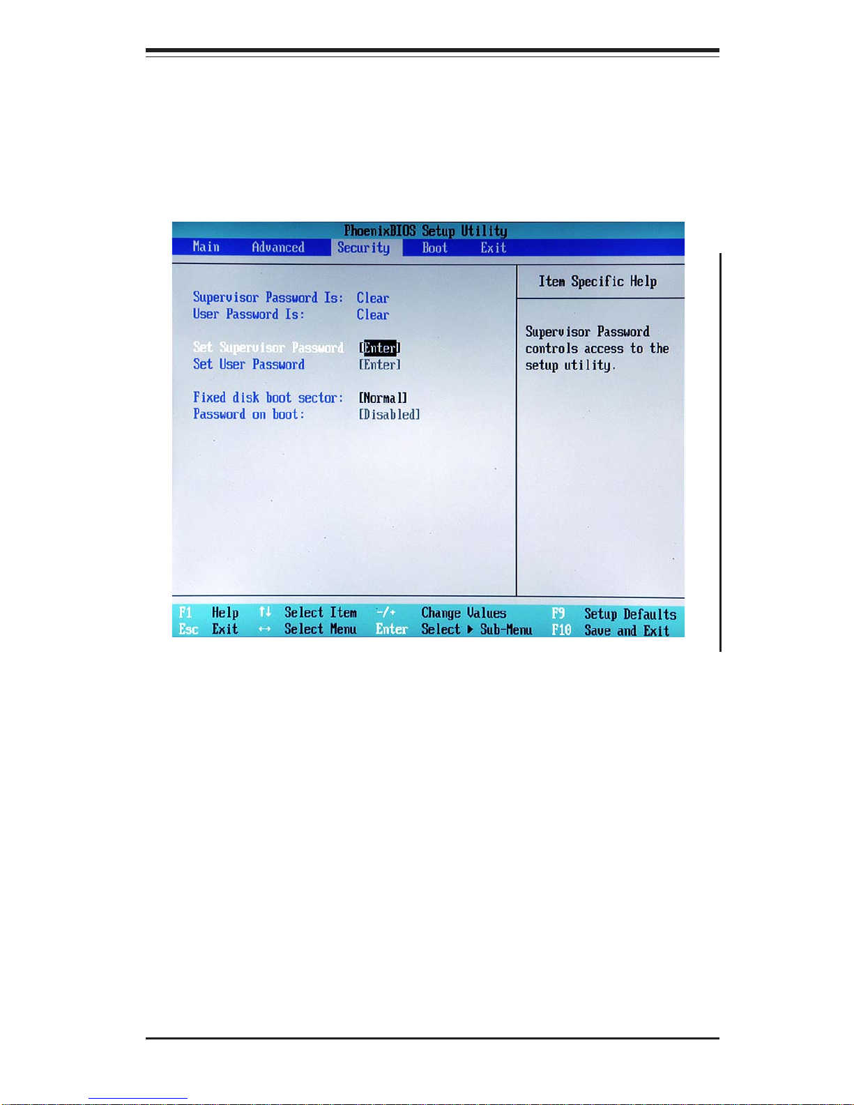
Chapter 7: BIOS
7-19
7-5 Security
Choose Security from the Phoenix BIOS Setup Utility main menu with the arrow
keys. You should see the following display. Security setting options are
displayed by highlighting the setting using the arrow keys and pressing <Enter>.
All Security BIOS settings are described in this section.
Supervisor Password Is:
This displays whether a supervisor password has been entered for the
system. Clear means such a password has not been used and Set means
a supervisor password has been entered for the system.
User Password Is:
This displays whether a user password has been entered for the system.
Clear means such a password has not been used and Set means a user
password has been entered for the system.
Page 88

7-20
SUPERWORKSTATION 7044A-82/7044A-8/7044A-i2/7044A-i Manual
Set Supervisor Password
When the item "Set Supervisor Password" is highlighted, hit the <Enter> key.
When prompted, type the Supervisor's password in the dialogue box to set
or to change supervisor's password, which allows access to the BIOS.
Set User Password
When the item "Set User Password" is highlighted, hit the <Enter> key.
When prompted, type the user's password in the dialogue box to set or to
change the user's password, which allows access to the system at bootup.
Fixed Disk Boot Sector
This setting may offer some protection against viruses when set to Write
Protect, which protects the boot sector on the hard drive from having a
virus written to it. The other option is Normal.
Password on Boot
This setting allows you to require a password to be entered when the
system boots up. The options are Enabled (password required) and
Disabled (password not required).
Page 89
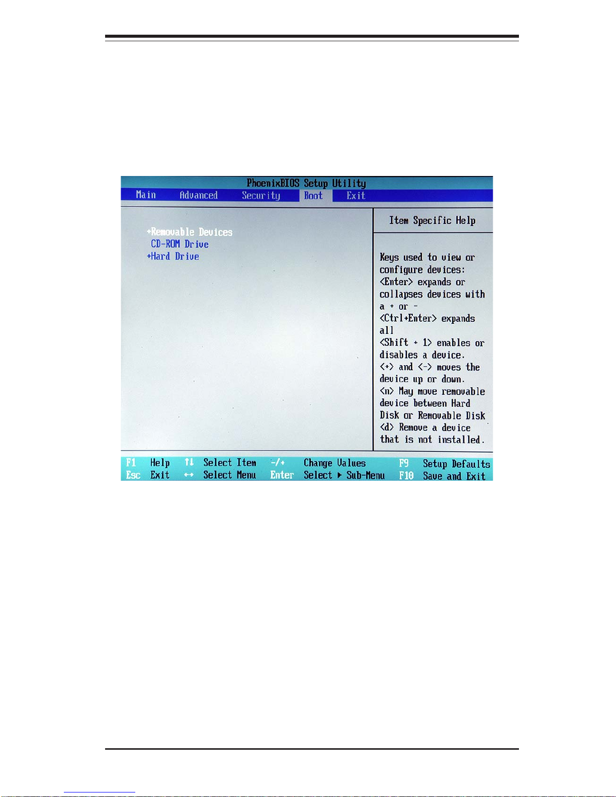
Chapter 7: BIOS
7-21
7-6 Boot
Choose Boot from the Phoenix BIOS Setup Utility main menu with the arrow keys.
You should see the following display. Highlighting a setting with a + or - will
expand or collapse that entry. See details on how to change the order and specs
of boot devices in the Item Specific Help window. All Boot BIOS settings are
described in this section.
+Removable Devices
Highlight and press <Enter> to expand the field. See details on how to
change the order and specs of devices in the Item Specific Help window.
CD-ROM Drive
See details on how to change the order and specs of the CD-ROM drive in
the Item Specific Help window.
+Hard Drive
Highlight and press <Enter> to expand the field. See details on how to
change the order and specs of hard drives in the Item Specific Help
window.
Page 90
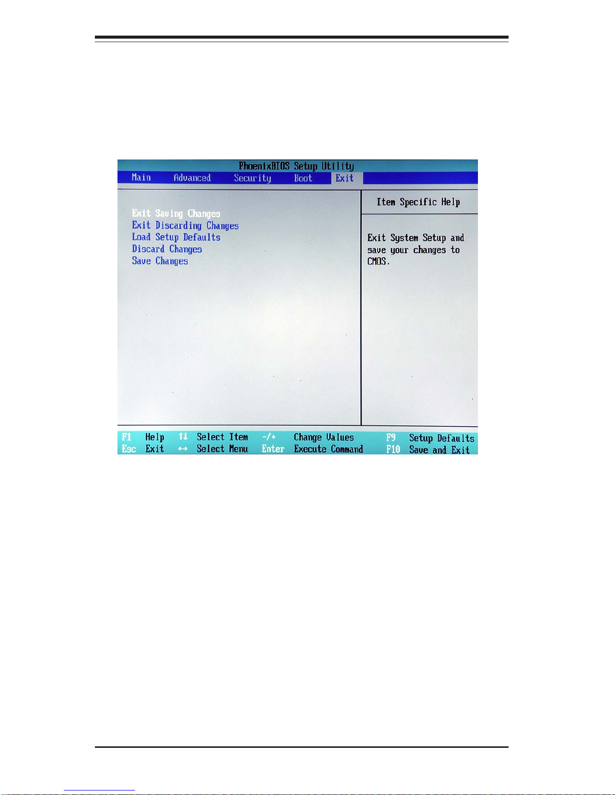
7-22
SUPERWORKSTATION 7044A-82/7044A-8/7044A-i2/7044A-i Manual
7-7 Exit
Choose Exit from the Phoenix BIOS Setup Utility main menu with the arrow keys.
You should see the following display. All Exit BIOS settings are described in this
section.
Exit Saving Changes
Highlight this item and hit <Enter> to save any changes you made and to
exit the BIOS Setup utility.
Exit Discarding Changes
Highlight this item and hit <Enter> to exit the BIOS Setup utility without saving
any changes you may have made.
Load Setup Defaults
Highlight this item and hit <Enter> to load the default settings for all items in
the BIOS Setup. These are the safest settings to use.
Page 91

Chapter 7: BIOS
7-23
Discard Changes
Highlight this item and hit <Enter> to discard (cancel) any changes you
made. You will remain in the Setup utility.
Save Changes
Highlight this item and hit <Enter> to save any changes you made. You will
remain in the Setup utility.
Page 92

7-24
SUPERWORKSTATION 7044A-82/7044A-8/7044A-i2/7044A-i Manual
Notes
Page 93

Appendix A: BIOS POST Codes
A-1
This section lists the POST (Power On Self Test) codes for the PhoenixBIOS. POST
codes are divided into two categories: recoverable and terminal.
Recoverable POST Errors
When a recoverable type of error occurs during POST, the BIOS will display an
POST code that describes the problem. BIOS may also issue one of the following beep codes:
1 long and two short beeps - video configuration error
1 continuous long beep - no memory detected
Terminal POST Errors
If a terminal type of error occurs, BIOS will shut down the system. Before doing
so, BIOS will write the error to port 80h, attempt to initialize video and write the
error in the top left corner of the screen.
The following is a list of codes that may be written to port 80h.
Appendix A
BIOS POST Codes
POST Code Description
02 h Verify Real Mode
03h Disable Non-Maskable Interrupt (NMI)
04 h Get CPU type
06 h Initialize system hardware
07 h Disable shadow and execute code from the ROM.
08 h Initialize chipset with initial POST values
09 h Set IN POST flag
0Ah Initialize CPU registers
0Bh Enable CPU cache
0C h Initialize caches to initial POST values
0Eh Initialize I/O component
0F h Initialize the local bus IDE
10 h Initialize Power Management
11 h Load alternate registers with initial POST values
12 h Restore CPU control word during warm boot
13 h Initialize PCI Bus Mastering devices
14 h Initialize keyboard controller
16 h 1-2-2-3 BIOS ROM checksum
17 h Initialize cache before memory Auto size
Page 94

A-2
SUPERWORKSTATION 7044A-82/7044A-8/7044A-i2/7044A-i Manual
POST Code Description
18 h 8254 timer initialization
1Ah 8237 DMA controller initialization
1C h Reset Programmable Interrupt Controller
20 h 1-3-1-1 Test DRAM refresh
22 h 1-3-1-3 Test 8742 Keyboard Controller
24h Set ES segment register to 4 GB
28h Auto size DRAM
29 h Initialize POST Memory Manager
2Ah Clear 512 kB base RAM
2C h 1-3-4-1 RAM failure on address line xxxx*
2Eh 1-3-4-3 RAM failure on data bits xxxx* of low byte of memory bus
2F h Enable cache before system BIOS shadow
32 h Test CPU bus-clock frequency
33 h Initialize Phoenix Dispatch Manager
36 h Warm start shut down
38 h Shadow system BIOS ROM
3Ah Auto size cache
3C h Advanced configuration of chipset registers
3D h Load alternate registers with CMOS values
41 h Initialize extended memory for RomPilot
42 h Initialize interrupt vectors
45 h POST device initialization
46 h 2-1-2-3 Check ROM copyright notice
47 h Initialize I20 support
48 h Check video configuration against CMOS
49 h Initialize PCI bus and devices
4Ah Initialize all video adapters in system
4Bh QuietBoot start (optional)
4C h Shadow video BIOS ROM
4Eh Display BIOS copyright notice
4F h Initialize MultiBoot
50 h Display CPU type and speed
51 h Initialize EISA board
52 h Test keyboard
54h Set key click if enabled
55 h Enable USB devices
58 h 2-2-3-1 Test for unexpected interrupts
59 h Initialize POST display service
5Ah Display prompt “Press F2 to enter SETUP”
5Bh Disable CPU cache
Page 95

Appendix A: BIOS POST Codes
A-3
POST Code Description
5C h Test RAM between 512 and 640 kB
60 h Test extended memory
62 h Test extended memory address lines
64 h Jump to UserPatch1
66h Configure advanced cache registers
67 h Initialize Multi Processor APIC
68 h Enable external and CPU caches
69 h Setup System Management Mode (SMM) area
6Ah Display external L2 cache size
6Bh Load custom defaults (optional)
6C h Display shadow-area message
6Eh Display possible high address for UMB recovery
70 h Display error messages
72 h Check for configuration errors
76 h Check for keyboard errors
7C h Set up hardware interrupt vectors
7D h Initialize Intelligent System Monitoring
7Eh Initialize coprocessor if present
80 h Disable onboard Super I/O ports and IRQs
81 h Late POST device initialization
82 h Detect and install external RS232 ports
83h Configure non-MCD IDE controllers
84 h Detect and install external parallel ports
85 h Initialize PC-compatible PnP ISA devices
86 h Re-initialize onboard I/O ports.
87h Configure Motherboard Configurable Devices (optional)
88 h Initialize BIOS Data Area
89 h Enable Non-Maskable Interrupts (NMIs)
8Ah Initialize Extended BIOS Data Area
8Bh Test and initialize PS/2 mouse
8C h Initialize floppy controller
8Fh Determine number of ATA drives (optional)
90 h Initialize hard-disk controllers
91 h Initialize local-bus hard-disk controllers
92 h Jump to UserPatch2
93 h Build MPTABLE for multi-processor boards
95 h Install CD ROM for boot
96 h Clear huge ES segment register
97h Fix up Multi Processor table
98 h 1-2 Search for option ROMs. One long, two short beeps on
checksum failure
Page 96

A-4
SUPERWORKSTATION 7044A-82/7044A-8/7044A-i2/7044A-i Manual
POST Code Description
99 h Check for SMART Drive (optional)
9Ah Shadow option ROMs
9C h Set up Power Management
9D h Initialize security engine (optional)
9Eh Enable hardware interrupts
9F h Determine number of ATA and SCSI drives
A0h Set time of day
A2h Check key lock
A4h Initialize typematic rate
A8h Erase F2 prompt
AAh Scan for F2 key stroke
ACh Enter SETUP
AEh Clear Boot flag
B0h Check for errors
B1h Inform RomPilot about the end of POST.
B2h POST done - prepare to boot operating system
B4h 1 One short beep before boot
B5h Terminate QuietBoot (optional)
B6h Check password (optional)
B7h Initialize ACPI BIOS
B9h Prepare Boot
BAh Initialize SMBIOS
BBh Initialize PnP Option ROMs
BC h Clear parity checkers
BD h Display MultiBoot menu
BEh Clear screen (optional)
BFh Check virus and backup reminders
C0 h Try to boot with INT 19
C1 h Initialize POST Error Manager (PEM)
C2 h Initialize error logging
C3 h Initialize error display function
C4 h Initialize system error handler
C5 h PnPnd dual CMOS (optional)
C6 h Initialize note dock (optional)
C7h Initialize note dock late
C8 h Force check (optional)
C9 h Extended checksum (optional)
CA h Redirect Int 15h to enable remote keyboard
CB h Redirect Int 13h to Memory Technologies
Devices such as ROM, RAM, PCMCIA, and serial disk
CC h Redirect Int 10h to enable remote serial video
Page 97

Appendix A: BIOS POST Codes
A-5
POST Code Description
CD h Re-map I/O and memory for PCMCIA
CE h Initialize digitizer and display message
D2 h Unknown interrupt
The following are for boot block in Flash ROM
POST Code Description
E0h Initialize the chipset
E1h Initialize the bridge
E2h Initialize the CPU
E3h Initialize system timer
E4h Initialize system I/O
E5h Check force recovery boot
E6h Checksum BIOS ROM
E7h Go to BIOS
E8h Set Huge Segment
E9h Initialize Multi Processor
EAh Initialize OEM special code
EBh Initialize PIC and DMA
EC h Initialize Memory type
ED h Initialize Memory size
EEh Shadow Boot Block
EFh System memory test
F0h Initialize interrupt vectors
F1 h Initialize Run Time Clock
F2h Initialize video
F3 h Initialize System Management Manager
F4 h Output one beep
F5h Clear Huge Segment
F6 h Boot to Mini DOS
F7 h Boot to Full DOS
* If the BIOS detects error 2C, 2E, or 30 (base 512K RAM error), it displays an additional
word-bitmap (xxxx) indicating the address line or bits that failed. For example, “2C
0002” means address line 1 (bit one set) has failed. “2E 1020" means data bits 12
and 5 (bits 12 and 5 set) have failed in the lower 16 bits. The BIOS also sends the
bitmap to the port-80 LED display. It first displays the checkpoint code, followed by
a delay, the high-order byte, another delay, and then the loworder byte of the error.
It repeats this sequence continuously.
Page 98

A-6
SUPERWORKSTATION 7044A-82/7044A-8/7044A-i2/7044A-i Manual
Notes
Page 99

Appendix B: Software Installation
B-1
Appendix B
Software Installation
After all the hardware has been installed, you must first configure the Adaptec
Embedded Serial ATA RAID Driver before you install the Windows operating
system. The necessary drivers are all included on the Supermicro bootable CDs
that came packaged with your motherboard.
B-1 Adaptec Embedded SATA RAID Controller Driver
Serial ATA (SATA)
Serial ATA (SATA) is a physical storage interface. It uses a single cable with a
minimum of four wires to create a point-to-point connection between devices. It
is a serial link which supports SATA transfer rates from 150MBps. Because the
serial cables used in SATA are thinner than the traditional cables used in Parallel
ATA (PATA), SATA systems have better airflow and can be installed in smaller
chassis than PATA. In addition, the cables used in PATA can only extend to
40cm long, while SATA cables can extend up to one meter. Overall, SATA
provides better functionality than PATA.
Intel ICH5R Controller Hub
Located in the South Bridge of the Intel E7525 (Tumwater) Chipset, the ICH5R I/O
Controller Hub provides the I/O subsystem with access to the rest of the system.
It supports 2-channel Ultra ATA/100 Bus Master IDE controller (PATA) and two
channel SATA Host Controllers, which support up to two Serial ATA ports and up
to two RAID drives.
Page 100

B-2
SUPERWORKSTATION 7044A-82/7044A-8/7044A-i2/7044A-i Manual
Configuring BIOS for SATA RAID Functions
1. Press the <Del> key during system bootup to enter the BIOS Setup Utility.
Note: If it is the first time to power on the system, we recommend that you load
the Optimized Default Settings. If you have already done so, please skip to Step
3.
2. Use the arrow keys to select the "Exit" Menu. Once in the "Exit" Menu, scroll
down the menu to select the item- "Load Optimized Default settings" and press
the <Enter> key. Select "OK" to confirm the selection. Press the <Enter> key
to load the default settings to the BIOS.
3. Use the arrow keys to select the "Main" Menu in the BIOS.
4. Scroll down to the next item-"SATA RAID Enable", select "Enabled" and press
<Enter>.
5. Tap the <Esc> key and scroll down to "Exit". Select "Save and Exit" from
the "Exit" menu. Press the <Enter> key to save the changes and exit the BIOS.
6. Once you've exited the BIOS Utility, the system will re-boot.
7. During the system startup, press the <Ctrl> and the <A> keys simultaneously
to run the Adaptec RAID Configuration Utility when prompted by the following
message:
Press <Ctrl><A> for Adaptec RAID Configuration Utility
 Loading...