

Supero SuperWorkstation 7033A-T User Manual
®
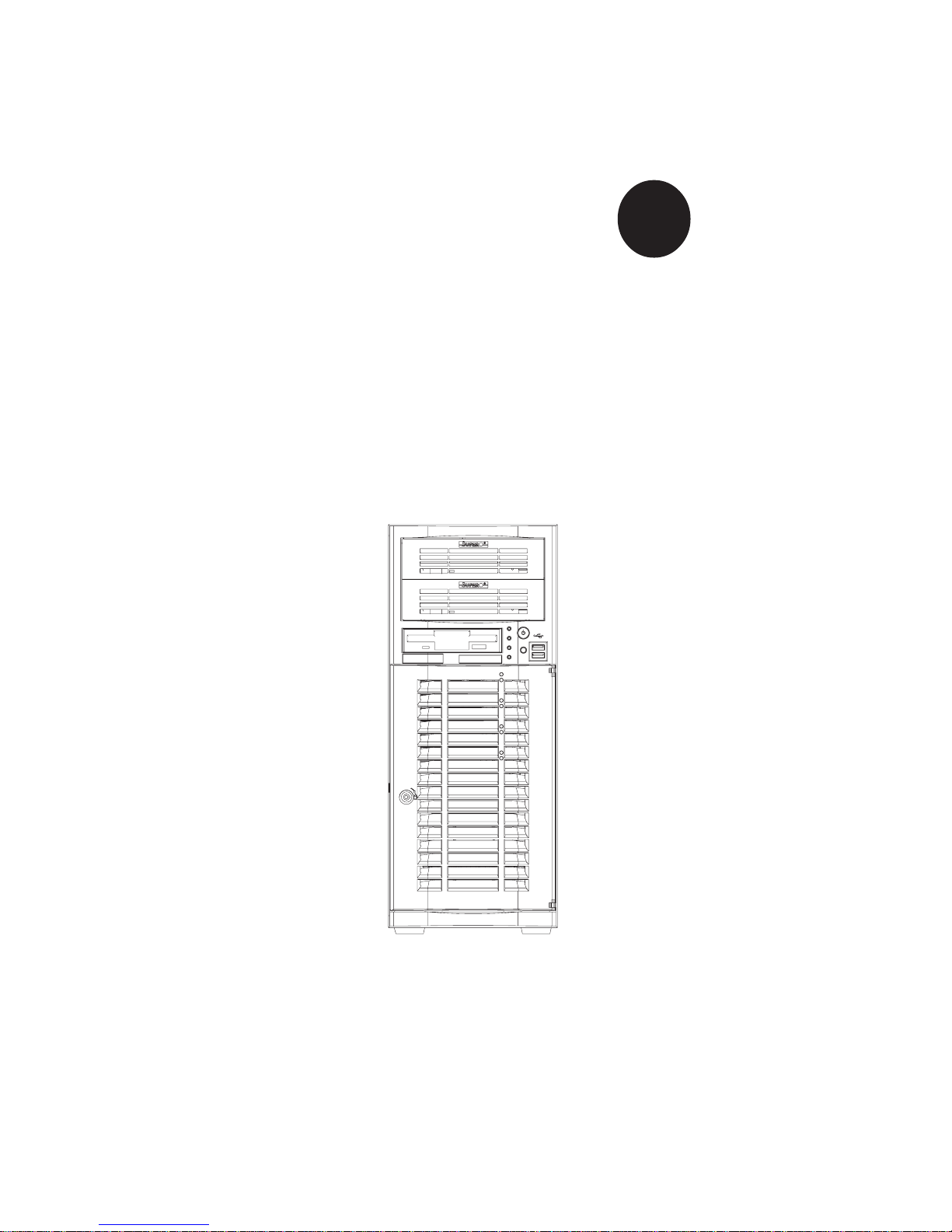
SUPERWORKSTATION 7033A-T
USER’S MANUAL
1.0a
SUPER

The information in this User’s Manual has been carefully reviewed and is believed to be
accurate. The vendor assumes no responsibility for any inaccuracies that may be
contained in this document, makes no commitment to update or to keep current the
information in this manual, or to notify any person or organization of the updates.
Please
Note: For the most up-to-date version of this manual, please see our
web site at www.supermicro.com.
SUPERMICRO COMPUTER reserves the right to make changes to the product described in
this manual at any time and without notice. This product, including software, if any, and
documentation may not, in whole or in part, be copied, photocopied, reproduced, translated
or reduced to any medium or machine without prior written consent.
IN NO EVENT WILL SUPERMICRO COMPUTER BE LIABLE FOR DIRECT, INDIRECT,
SPECIAL, INCIDENTAL, SPECULATIVE OR CONSEQUENTIAL DAMAGES ARISING FROM
THE USE OR INABILITY TO USE THIS PRODUCT OR DOCUMENTATION, EVEN IF
ADVISED OF THE POSSIBILITY OF SUCH DAMAGES. IN PARTICULAR, THE VENDOR
SHALL NOT HAVE LIABILITY FOR ANY HARDWARE, SOFTWARE, OR DATA STORED
OR USED WITH THE PRODUCT, INCLUDING THE COSTS OF REPAIRING, REPLACING,
INTEGRATING, INSTALLING OR RECOVERING SUCH HARDWARE, SOFTWARE, OR
DATA.
Any disputes arising between manufacturer and customer shall be governed by the laws of
Santa Clara County in the State of California, USA. The State of California, County of
Santa Clara shall be the exclusive venue for the resolution of any such disputes.
Supermicro's total liability for all claims will not exceed the price paid for the hardware
product.
Unless you request and receive written permission from SUPER MICRO COMPUTER, you
may not copy any part of this document.
Information in this document is subject to change without notice. Other products and
companies referred to herein are trademarks or registered trademarks of their respective
companies or mark holders.
Copyright © 2005 by SUPER MICRO COMPUTER INC.
All rights reserved.
Printed in the United States of America

iii
Preface
Preface
About This Manual
This manual is written for professional system integrators and PC technicians. It provides information for the installation and use of the
SuperWorkstation 7033A-T. Installation and maintainance should be performed by experienced technicians only.
The SuperWorkstation 7033A-T is a high-end, dual processor tower server
based on the SC733T-450 workstation/server chassis and the X5DAL-TG2,
a dual processor motherboard that supports single or dual Intel Xeon® processors up to 3.06 GHz at a Front Side (System) Bus speed of 533/400
MHz and up to 8 GB DDR-266/200 (PC2100/1600) SDRAM main memory.
Manual Organization
Chapter 1: Introduction
The first chapter provides a checklist of the main components included with
the system and describes the main features of the SUPER X5DAL-TG2
mainboard and the SC733T-450 chassis, which comprise the
SuperWorkstation 7033A-T.
Chapter 2: Server Installation
This chapter describes the steps necessary to set up and check out the
configuration of the SuperWorkstation 7033A-T prior to powering up the
system. If your system was ordered without processor and memory components, this chapter will refer you to the appropriate sections of the
manual for their installation.
Chapter 3: System Interface
Refer here for details on the system interface, which includes the functions
and information provided by the control panel on the chassis as well as
other LEDs located throughout the system.

SUPERWORKSTATION 7033A-T Manual
iv
Chapter 4: System Safety
You should thoroughly familiarize yourself with this chapter for a general
overview of safety precautions that should be followed when installing and
servicing the SuperWorkstation 7033A-T.
Chapter 5: Advanced Motherboard Setup
Chapter 5 provides detailed information on the X5DAL-TG2 motherboard,
including the locations and functions of connections, headers and jumpers.
Refer to this chapter when adding or removing processors or main memory
and when reconfiguring the motherboard.
Chapter 6: Advanced Chassis Setup
Refer to Chapter 6 for detailed information on the SC733T-450 chassis.
You should follow the procedures given in this chapter when installing,
removing or reconfiguring Serial ATA drives or peripheral drives and when
replacing system power supply units and cooling fans.
Chapter 7: BIOS
The BIOS chapter includes an introduction to BIOS and provides detailed
information on running the CMOS Setup Utility.
Appendix A: BIOS POST Messages
Appendix B: BIOS POST Codes
Appendix C: System Specifications

v
Preface
Notes

SUPERWORKSTATION 7033A-T Manual
vi
Table of Contents
Preface
About This Manual ...................................................................................................... iii
Manual Organization ................................................................................................... iii
Chapter 1: Introduction
1-1 Overview ......................................................................................................... 1-1
1-2 Server Chassis Features.............................................................................. 1-2
1-3 Mainboard Features ....................................................................................... 1-3
1-4 Contacting Supermicro .................................................................................. 1-5
Chapter 2: Server Installation
2-1 Overview ......................................................................................................... 2-1
2-2 Unpacking the 7033A-T ................................................................................. 2-1
2-3 Preparing for Setup ....................................................................................... 2-1
2- 4 Checking the Motherboard Setup ................................................................ 2-2
2-5 Checking the Drive Bay Setup ..................................................................... 2-4
Chapter 3: System Interface
3-1 Overview ......................................................................................................... 3-1
3- 2 Control Panel Buttons .................................................................................... 3-1
Power ........................................................................................................ 3-1
Reset.......................................................................................................... 3-2
3-3 Control Panel LEDs ........................................................................................ 3-2
Power ........................................................................................................ 3-2
HDD ............................................................................................................ 3-2
NIC .............................................................................................................. 3-2
Overheat ................................................................................................... 3-2
3-4 Serial ATA Drive Carrier LEDs .................................................................... 3-3
3- 5 LAN (Ethernet) Port LEDs ............................................................................. 3-4
Chapter 4: System Safety
4-1 Electrical Safety Precautions ........................................................................ 4-1
4-2 General Safety Precautions .......................................................................... 4-2
4-3 ESD Safety Precautions .................................................................................4-3
4-4 Operating Precautions .................................................................................... 4-4

Chapter 5: Advanced Motherboard Setup
5- 1 Handling the X5DAL-TG2 Motherboard ....................................................... 5-1
5-2 PGA Processor and Heatsink Installation ................................................... 5-2
5-3 Connecting Cables .......................................................................................... 5-5
Connecting Data Cables .......................................................................... 5-5
Connecting Power Cables....................................................................... 5-5
Connecting the Control Panel ................................................................. 5-6
5- 4 I/O Ports ............................................................................................................ 5-7
5- 5 Installing Memory............................................................................................. 5-7
5- 6 Adding PCI Cards ............................................................................................ 5-9
5- 7 Motherboard Details ...................................................................................... 5-10
X5DAL-TG2 Layout................................................................................. 5-10
X5DAL-TG2 Quick Reference............................................................... 5-11
5-8 Connector Definitions ................................................................................... 5-12
ATX Power Connector.......................................................................... 5-12
Processor Power Connector................................................................ 5-12
NMI Button ................................................................................................ 5-12
Power LED ............................................................................................... 5-12
HDD LED .................................................................................................. 5-13
NIC1 LED .................................................................................................. 5-13
NIC2 LED .................................................................................................. 5-13
Overheat LED (OH) ............................................................................... 5-13
Power Fail LED ...................................................................................... 5-13
Reset Button ........................................................................................... 5-14
Power Button .......................................................................................... 5-14
Chassis Intrusion .................................................................................... 5-14
Universal Serial Bus (USB0/1) ............................................................ 5-14
Front Panel Universal Serial Bus Headers ........................................ 5-15
Serial Ports .............................................................................................. 5-15
GLAN1/2 (Ethernet Ports) .................................................................... 5-15
ATX PS/2 Keyboard and Mouse Ports ................................................5-15
Fan Headers ............................................................................................5-16
Power LED/Speaker ............................................................................... 5-16
Third Power Supply Fail Header .......................................................... 5-16
Wake-On-LAN ......................................................................................... 5-17
Wake-On-Ring ........................................................................................ 5-17
Keylock .................................................................................................... 5-17
vii
Table of Contents

SUPERWORKSTATION 7033A-T Manual
viii
5- 9 Jumper Settings ............................................................................................. 5-18
Explanation of Jumpers ......................................................................... 5-18
CMOS Clear.............................................................................................. 5-18
System Bus Speed ................................................................................. 5-18
GLAN Enable/Disable............................................................................. 5-19
Power Fail Alarm Enable/Disable ......................................................... 5-19
Watch Dog Enable/Disable .................................................................... 5-19
Thermal Fan Control ............................................................................... 5-20
Serial ATA Enable/Disable .................................................................... 5-20
Keyboard Wakeup ................................................................................. 5-20
5-10 Onboard Indicators ....................................................................................... 5-21
GLAN LEDs.............................................................................................. 5-21
Overheat LEDs ........................................................................................ 5-21
5-11 Parallel Port and Floppy/Hard Drive Connections .................................... 5-22
Parallel (Printer) Port Connector ......................................................... 5-22
Floppy Connector ................................................................................... 5-23
IDE Connectors ...................................................................................... 5-23
5-12 Installing Software Drivers.......................................................................... 5-24
Chapter 6: Advanced Chassis Setup
6-1 Static-Sensitive Devices ................................................................................ 6-1
6- 2 Front Control Panel ......................................................................................... 6-2
6-3 System Fans .................................................................................................... 6-5
Fan Failure................................................................................................. 6-5
Replacing System Fans ........................................................................... 6-5
6-4 Drive Bay Installation ...................................................................................... 6-6
Serial ATA Drives.................................................................................... 6-6
Installing Components in the 5 1/4" Drive Bays ................................. 6-9
6-5 Power Supply ................................................................................................ 6-10
Power Supply Failure ............................................................................ 6-10
Replacing the Power Supply ................................................................ 6-10
Chapter 7: BIOS
7- 1 Introduction....................................................................................................... 7-1
7- 2 Running Setup.................................................................................................. 7-2
7- 3 Main BIOS Setup.............................................................................................. 7-2
7-4 Advanced Setup.............................................................................................. 7-6
7-5 Security ........................................................................................................... 7-16
7- 6 Boot ................................................................................................................. 7-18
7-7 Exit ................................................................................................................... 7-19

Table of Contents
ix
Appendices:
Appendix A: BIOS POST Messages ..................................................................... A-1
Appendix B: BIOS POST Codes ............................................................................. B-1
Appendix C: System Specifications ...................................................................... C-1

Notes
SUPERWORKSTATION 7033A-T Manual
x

1-1
Chapter 1: Introduction
Chapter 1
Introduction
1-1 Overview
Supermicro's SuperWorkstation 7033A-T is a high-end dual processor workstation. The 7033A-T is comprised of two main subsystems: the SC733T450 chassis and the X5DAL-TG2 motherboard. Please refer to our web site
for information on operating systems that have been certified for use with
the SuperWorkstation 7033A-T.
In addition to the motherboard and chassis, various hardware components
have been included with the SuperWorkstation 7033A-T, as listed below:
z Two (2) CPU heatsinks (Fan-050-CFT)
z Two (2) heatsink retention clip assemblies (SKT-095-604E)
z One (1) 3.5" floppy drive
z Two (2) 5.25" drive bays (one with drive tray)
z One (1) ribbon cable for floppy drives (CBL-0051)
z One (1) ribbon cable for IDE CD-ROM drive (CBL-0052)
z Four (4) cables for Serial ATA hard drives (CBL-0044)
z One (1) 10-pin to 10-pin SATA LED cable (CBL-0056)
z One (1) CD containing drivers and utilities
z SuperServer 7033A-T User's Manual
Chapter 1: Introduction

SUPERWORKSTATION 7033A-T Manual
1-2
1-2 Chassis Features
The SuperWorkstation 7033A-T is a high-end, mid-tower workstation chassis designed with today's most state-of-the-art features. The following is a
general outline of the main features of the SC733T-450 chassis.
System Power
The 7033A-T includes a single 450W redundant cooling power supply that
features noise-suppression technology for silent operation.
Serial ATA Subsystem
The chassis was designed to support four Serial ATA hard drives, which
are also hot-swappable units. ATA/100 IDE drives are also supported.
Note: The operating system you use must have RAID support to enable the
hot-swap capability of the Serial ATA drives.
Front Control Panel
The control panel of the SuperWorkstation 7033A-T provides you with several system monitoring and control functions. LEDs indicate system power,
hard drive activity, network activity and overheat conditions. A main power
button and a system reset button are also included on the front panel.
I/O Backplane
The SC733T-450 is an ATX form factor tower chassis. The I/O backplane
accommodates seven motherboard expansion slots, two COM ports, a parallel port, two USB ports, PS/2 mouse and keyboard ports and two G-bit
Ethernet ports.
Cooling System
The SC733T-450 chassis has an advanced cooling design that includes one
9-cm system cooling fan and one 12-cm exhaust fan. The 9-cm fan sits
inside an air shroud that efficiently distributes air throughout the system.
All chassis and power supply fans operate continuously, except for the
secondary power supply fan, which activates only when the primary fails
or the temperature becomes too high. The primary power supply fan, the 9cm system cooling fan and the 12-cm exhaust fan all have a thermal feature
that allows them to run slower and therefore quieter.

1-3
Chapter 1: Introduction
1-3 Motherboard Features
At the heart of the SuperWorkstation 7033A-T lies the X5DAL-TG2, a dual
processor motherboard designed to provide maximum performance. Below
are the main features of the X5DAL-TG2.
Processors
The X5DAL-TG2 supports single or dual 604/603-pin Intel Xeon processors
of up to 3.06 GHz with a 533/400 MHz FSB. Please refer to the motherboard
description pages on our web site for a complete listing of supported processors (http://www.supermicro.com/Product_page/product-m.htm).
Memory
The X5DAL-TG2 has four 184-pin DIMM slots that can support up to 8 GB of
registered ECC or non-ECC (unbuffered) DDR-266/200 (PC2100/1600)
SDRAM. Module sizes of 128MB, 256MB, 512MB 1GB and 2GB may be
used to populate the DIMM slots. (The X5DAL-TG2 was designed to support
2GB modules in each slot, however 2GB size memory modules have not yet
been validated.) It is recommended that you do not mix memory modules of
different types and speeds.
Serial ATA
Two Silicon Image Serial ATA controllers are integrated into the X5DAL-TG2
to provide a four-port Serial ATA subsystem, which is RAID 0 and RAID 1
supported. The Serial ATA drives are hot-swappable units.
Note: The operating system you use must have RAID support to enable the
hot-swap capability and RAID function of the Serial ATA drives.
PCI Expansion Slots
The X5DAL-TG2 has one 64-bit 100 MHz PCI-X slot, one 64-bit 66 MHz PCI
slot, two 32-bit 33 MHz PCI slots and one 8xAGP Pro (1.5V) slot, which is
used for video cards. The speed of the PCI-X slots may be changed in
BIOS. See Chapter 7 for details.

SUPERWORKSTATION 7033A-T Manual
1-4
Onboard Controllers/Ports
In addition to the Serial ATA controller, one floppy drive controller and an
onboard ATA/100 controller (which supports up to four hard drives or
ATAPI devices) are provided. The color-coded I/O ports include two COM
ports, a parallel port, two USB ports, PS/2 mouse and keyboard ports and
two G-bit Ethernet ports. Two front side USB ports are also included on the
front of the chassis.
Other Features
Other onboard features that promote system health include onboard voltage
monitors, a chassis intrusion header, auto-switching voltage regulators,
chassis and CPU overheat sensors, virus protection and BIOS rescue.

1-5
Chapter 1: Introduction
1-4 Contacting Supermicro
Headquarters
Address: SuperMicro Computer, Inc.
980 Rock Ave.
San Jose, CA 95131 U.S.A.
Tel: +1 (408) 503-8000
Fax: +1 (408) 503-8008
Email: marketing@supermicro.com (General Information)
support@supermicro.com (Technical Support)
Web Site: www.supermicro.com
Europe
Address: SuperMicro Computer B.V.
Het Sterrenbeeld 28, 5215 ML
's-Hertogenbosch, The Netherlands
Tel: +31 (0) 73-6400390
Fax: +31 (0) 73-6416525
Email: sales@supermicro.nl (General Information)
support@supermicro.nl (Technical Support)
rma@supermicro.nl (Customer Support)
Asia-Pacific
Address: SuperMicro, Taiwan
4F, No. 232-1, Liancheng Rd.
Chung-Ho 235, Taipei County
Taiwan, R.O.C.
Tel: +886-(2) 8226-3990
Fax: +886-(2) 8226-3991
Web Site: www.supermicro.com.tw
Technical Support:
Email: support@supermicro.com.tw
Tel: 886-2-8228-1366, ext.132 or 139

SUPERWORKSTATION 7033A-T Manual
1-6
Notes

Chapter 2: Server Installation
2-1
Chapter 2
Server Installation
2-1 Overview
This chapter provides a quick setup checklist to get your SuperWorkstation
7033A-T up and running. Following these steps in the order given should
enable you to have the system operational in a minimal amount of time. This
quick setup assumes that your SuperWorkstation 7033A-T system has come
to you with the processors and memory preinstalled. If your system is not
already fully integrated with a motherboard, processors, system memory
etc., please turn to the chapter or section noted in each step for details on
installing specific components.
2-2 Unpacking the 7033A-T
You should inspect the box the SuperWorkstation 7033A-T was shipped in
and note if it was damaged in any way. If the workstation itself shows
damage you should file a damage claim with the carrier who delivered it.
2-3 Preparing for Setup
Choosing a Setup Location
Decide on a suitable location for the SuperWorkstation 7033A-T. It should
be situated in a clean, dust-free area that is well ventilated. Avoid areas
where heat, electrical noise and electromagnetic fields are generated. You
will also need it placed near a grounded power outlet. Once the system
has been placed in the appropriate location, slide the locking tabs on each
caster down to keep it stationary.

2-2
SUPERWORKSTATION 7033A-T Manual
Server Precautions
- Review the electrical and general safety precautions in Chapter 4.
- Use a regulating uninterruptible power supply (UPS) to protect the
server from power surges, voltage spikes and to keep your system
operating in case of a power failure.
- Allow the hot plug Serial ATA drives and power supply unit(s) to cool
before touching them.
- Always keep the chassis' front door and all panels closed when not
servicing to maintain proper cooling.
2-4 Checking the Motherboard Setup
After setting up the the 7033A-T, you will need to gain access to the inside
of the chassis to make sure the motherboard is properly installed and the
essential connections have been made. Begin by opening the left side
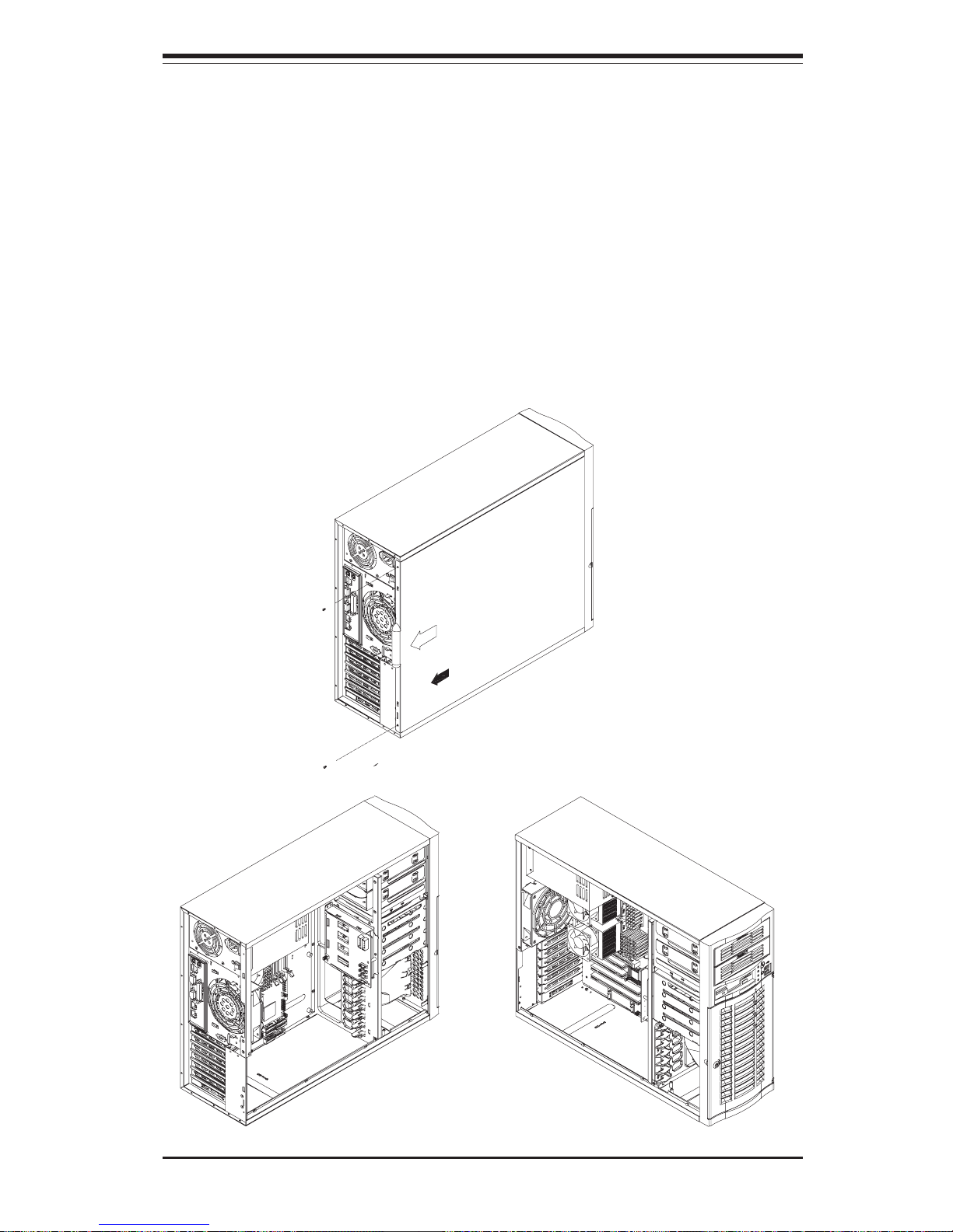
panel (when facing the front of the chassis). Refer to Figure 2-1 for the
following steps.
1. Remove the left side panel of the chassis
First, make sure the keylock for the side panel is unlocked. Then remove
the two screws that secure the back lip of the side panel to the rear of
the chassis. Grasp the handle at the rear of the panel and pull straight
back about 1/2 inch, at which point the panel should hit a stop. Swing the
top of the panel out and completely lift it away from the chassis. When
reinstalling this panel, make sure the raised holes along the bottom of the
chassis fit into the long holes in the bottom lip of the side panel.
2. Check the CPUs (processors)
You should have one or two processors already installed into the system
board. Each processor should have its own heatsink attached. See
Chapter 5 for instructions on processor installation.
3. Check the system memory
Your 7033A-T workstation may have come with system memory already
installed. Make sure all DIMMs are fully seated in their slots. For details
on adding system memory, refer to Chapter 5.
Chapter 2: Server Installation
2-3
4. Installing add-on cards
If desired, you can install add-on cards to the system. See Chapter 5 for
details on installing PCI add-on cards.
5. Check all cable connections and airflow
Make sure all power and data cables are properly connected and not
blocking the chassis airflow. See Chapter 5 for details on cable connections.
Figure 2-1. Accessing the Inside of the 7033A-T

2-4
SUPERWORKSTATION 7033A-T Manual
2-5 Checking the Drive Bay Setup
Next, you should check to make sure the peripheral drives and the Serial
ATA drives and Serial ATA backplane have been properly installed and all
connections have been made.
1. Accessing the drive bays
All drives can be accessed from the front of the server. When installing
or removing the CD-ROM, IDE hard drives or a floppy drive, you will also
need to remove the left chassis cover. The Serial ATA disk drives can
be installed and removed from the front of the chassis without removing
any chassis covers.
2. Installing components into the 5.25" drive bay
To install components into the 5.25" drive bays, you must first remove the
left chassis cover as described in the previous section. Refer to Chapter 6 for details.
3. Installing CD-ROM and floppy disk drives
Refer to Chapter 6 if you need to reinstall a CD-ROM and/or a floppy disk
drive to the system.
4. Check the Serial ATA disk drives
Depending upon your system's configuration, your system may have one
to four drives already installed. If you need to install Serial ATA drives,
please refer to Chapter 6.
5. Check the airflow
Airflow is provided by one 9-cm cooling fan and a 12-cm exhaust fan.
The system component layout was carefully designed to promote sufficient airflow through the chassis interior. A specially designed air
shroud enables the 9-cm fan to sufficiently supply cool air to all system
components. Also note that all power and data cables have been routed
in such a way that they do not block the airflow generated by the fans.
Keep this in mind when you reroute them after working on the system.
6. Supplying power to the system:
The last thing you must do is to provide input power to the system. Plug
the power cord from the power supply units into a high-quality power
strip that offers protection from electrical noise and power surges. It is
recommended that you use an uninterruptible power supply (UPS). Finally, depress the power on button on the front of the chassis.
Chapter 3: System Interface
3-1
Chapter 3
System Interface
3-1 Overview
There are several LEDs on the control panel as well as two for each Serial
ATA drive carrier and LAN (Ethernet) port. These LEDs are to keep you
constantly informed of the overall status of the system and the activity and
health of specific components. There are also two buttons on the chassis
control panel.
3-2 Control Panel Buttons
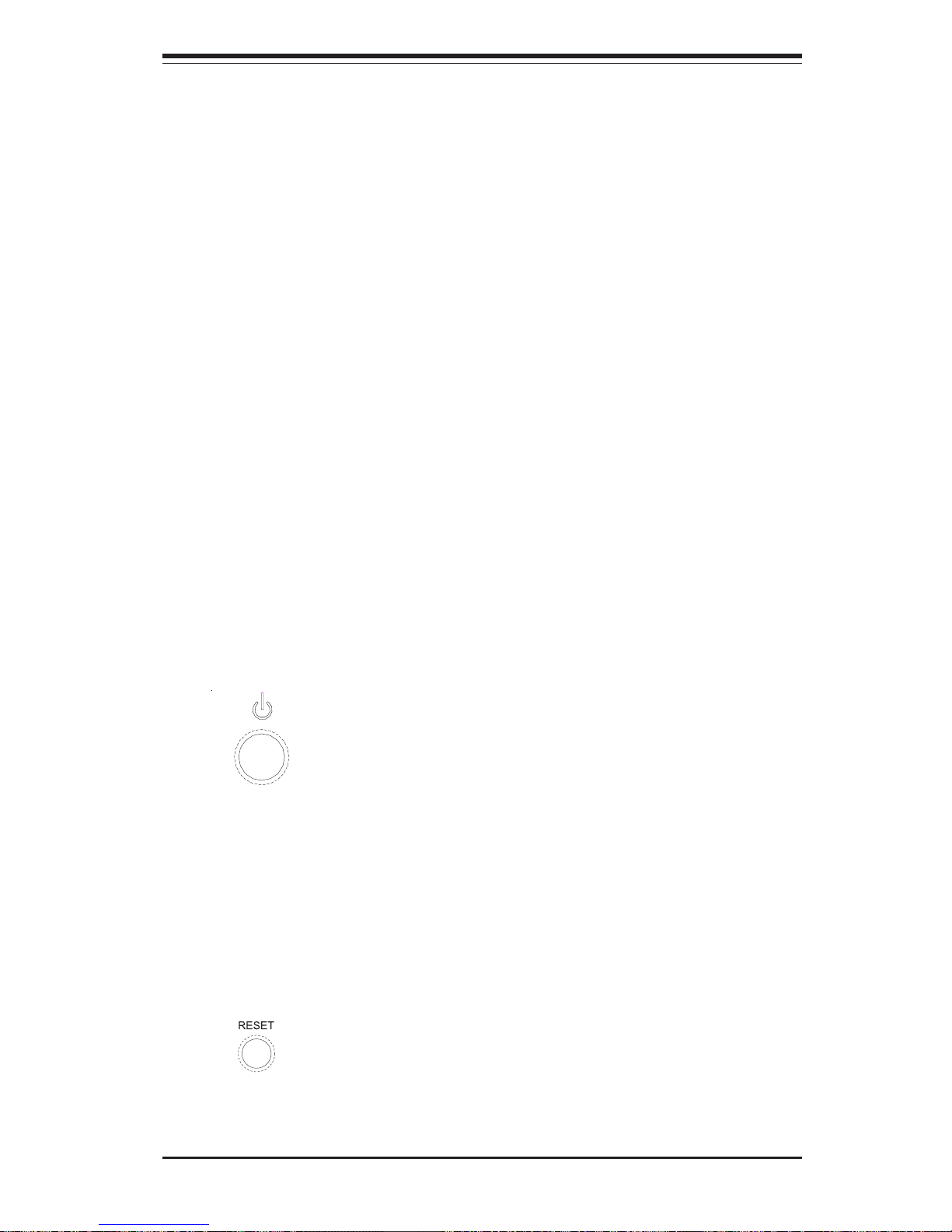
There are three push-button buttons located on the front of the chassis.
These are (in order from left to right) a power on/off button, an NMI (NonMaskable Interrupt) button and a reset button.
z POWER: This is the main power button, which is used to apply or turn
off the main system power. Turning off system power with this button
removes the main power but keeps standby power supplied to the system.
z RESET: Use the reset button to reboot the system.
3-2
SUPERWORKSTATION 7033A-T Manual
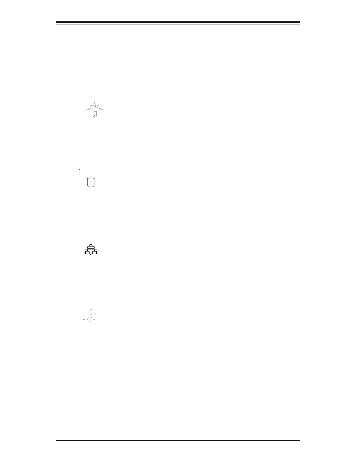
3-3 Control Panel LEDs
The control panel located on the front of the SC733T-450 chassis has six
LEDs that provide you with critical information related to different parts of
the system. This section explains what each LED indicates when illuminated and any corrective action you may need to take.
z Power: Indicates external power is being supplied to the system's
power supply unit. This LED should normally be illuminated when the system is operating.
z HDD: Indicates IDE channel activity. On the SuperWorkstation 7033A-
T, this LED indicates CD-ROM drive activity when flashing.
z NIC: Indicates network activity on the GLAN when flashing.
z Overheat: Indicates a processor overheat condition. This may be
caused by cables obstructing the airflow in the system or the ambient room
temperature being too warm. You should also check to make sure that the
chassis covers are installed and that all fans are present and operating
normally. Finally, verify that the heatsinks are installed properly (see Chapter 5).
NIC
Chapter 3: System Interface
3-3
3-4 Serial ATA Drive Carrier LEDs
Each Serial ATA drive carrier has two LEDs.
z Green: When illuminated, the green LED on the front of the drive
carrier indicates drive activity. A connection to the Serial ATA backplane
enables this LED to blink on and off when that particular drive is being
accessed.
z Red: A SAF-TE compliant backplane (not included) is needed to acti-
vate the red LEDs, which indicate a drive failure. Please refer to Chapter 6
for instructions on replacing failed Serial ATA drives.
3-5 LAN (Ethernet) Port LEDs
Each LAN port has a yellow and a green LED. The yellow (left) LED indicates activity while the other (right) LED may be green, orange or off to
indicate the speed of the connection. See the tables below for the functions associated with these LEDs.
LED
Color
Off
Green
Orange
Defin itio n
No Connection
100 MHz
1 GHz
Gb LAN Right LED
Indicator
LED
Color
Off
Yellow
Defin itio n
Not Ac tiv e
Active
Gb LAN Left LED
Indicator

3-4
SUPERWORKSTATION 7033A-T Manual
Notes
Chapter 4: System Safety
4-1
Chapter 4
System Safety
4-1 Electrical Safety Precautions
!
Basic electrical safety precautions should be followed to protect yourself
from harm and the SuperWorkstation 7033A-T from damage:
z Be aware of the locations of the power on/off switch on the chassis
as well as the room's emergency power-off switch, disconnection
switch or electrical outlet. If an electrical accident occurs, you can
then quickly remove power from the system.
z Do not work alone when working with high voltage components.
z Power should always be disconnected from the system when removing
or installing main system components, such as the motherboard,
memory modules, IDE hard drives and the CD-ROM and floppy drives.
When disconnecting power, you should first power down the system
with the operating system and then unplug the power cords of all the
power supply units in the system.
z When working around exposed electrical circuits, another person who
is familiar with the power-off controls should be nearby to switch off
the power if necessary.
z Use only one hand when working with powered-on electrical
equipment. This is to avoid making a complete circuit, which will
cause electrical shock. Use extreme caution when using metal tools,
which can easily damage any electrical components or circuit boards
they come into contact with.
z Do not use mats designed to decrease electrostatic discharge as
protection from electrical shock. Instead, use rubber mats that have
been specifically designed as electrical insulators.
4-2
SUPERWORKSTATION 7033A-T Manual
4-2 General Safety Precautions
Follow these rules to ensure general safety:
z Keep the area around the SuperWorkstation 7033A-T clean and free of
clutter.
z The SuperWorkstation 7033A-T weighs approximately 45 lbs. when fully
loaded. When lifting the system, two people at either end should lift
slowly with their feet spread out to distribute the weight. Always
keep your back straight and lift with your legs.
z Place the chassis top/side cover and any system components that have
been removed away from the system or on a table so that they won't
accidentally be stepped on.
z While working on the system, do not wear loose clothing such as
neckties and unbuttoned shirt sleeves, which can come into contact
with electrical circuits or be pulled into a cooling fan.
!
z The power supply power cord must include a grounding plug and must
be plugged into grounded electrical outlets.
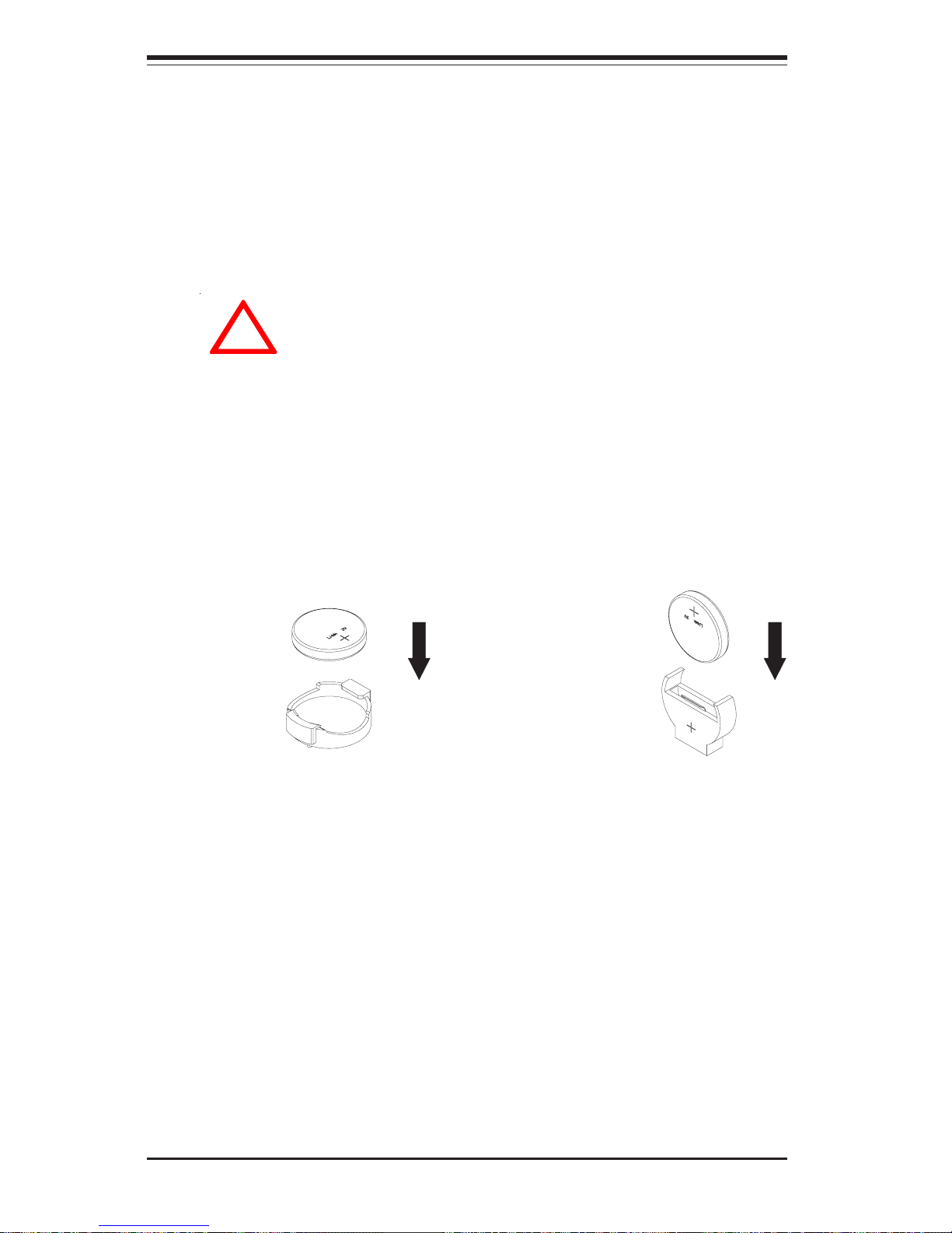
z Motherboard Battery: CAUTION - There is a danger of explosion if the
onboard battery is installed backwards, which will reverse its
polarities. The positive side of the battery should be facing up and
the negative side should facing the motherboard. This battery must
be replaced only with the same or an equivalent type recommended
by the manufacturer. Dispose of used batteries according to the
manufacturer's instructions. See Figure 4-1.
z CD-ROM Laser: CAUTION - this server may have come equipped with
a CD-ROM drive. To prevent direct exposure to the laser beam and
hazardous radiation exposure, do not open the enclosure or use the
unit in any unconventional way.
Chapter 4: System Safety
4-3
4-3 ESD Precautions
Electrostatic discharge (ESD) is generated by two objects with different
electrical charges coming into contact with each other. An electrical
discharge is created to neutralize this difference, which can damage
electronic components and printed circuit boards. The following
measures are generally sufficient to neutralize this difference before
contact is made to protect your equipment from ESD:
z Use a grounded wrist strap designed to prevent static discharge.
z Keep all components and printed circuit boards (PCBs) in their
antistatic bags until ready for use.
z Touch a grounded metal object before removing the board from the
antistatic bag.
z Do not let components or PCBs come into contact with your clothing,
which may retain a charge even if you are wearing a wrist strap.
z Handle a board by its edges only; do not touch its components,
peripheral chips, memory modules or contacts.
z When handling chips or modules, avoid touching their pins.
z Put the motherboard and peripherals back into their antistatic bags
when not in use.
!
z Remove any jewelry or metal objects from your body, which are
excellent metal conductors that can create short circuits and harm you
if they come into contact with printed circuit boards or areas where
power is present.
z After accessing the inside of the system, close the system back up
and after ensuring that all connections have been made.
4-4
SUPERWORKSTATION 7033A-T Manual
4-4 Operating Precautions
Care must be taken to assure that all chassis covers are in place when
the 7033A-T is operating to ensure proper cooling. Out of warranty
damage to the 7033A-T system can occur if this practice is not strictly
followed.
!
z For grounding purposes, make sure your computer chassis provides
excellent conductivity between the power supply, the case, the mounting
fasteners and the motherboard.
Figure 4-1. Installing the Onboard Battery
LITHIUM BATTERY
BATTERY HOLDER BATTERY HOLDER
LITHIUM BATTERY
OR

Chapter 5: Advanced Motherboard Setup
5-1
Chapter 5
Advanced Motherboard Setup
This chapter covers the steps required to install processors and heatsinks
to the X5DAL-TG2 motherboard, connect the data and power cables and
install add-on cards. All motherboard jumpers and connections are described and a layout and quick reference chart are included in this chapter.
Remember to close the chassis completely when you have finished working
on the motherboard to protect and cool the system sufficiently.
5-1 Handling the X5DAL-TG2 Motherboard
Static electrical discharge can damage electronic components. To prevent
damage to printed circuit boards, it is important to handle them very carefully (see Chapter 4). Also note that the size and weight of the motherboard can cause it to bend if handled improperly, which may result in damage. To prevent the motherboard from bending, keep one hand under the
center of the board to support it when handling. The following measures
are generally sufficient to protect your equipment from static discharge.
Precautions
• Use a grounded wrist strap designed to prevent static discharge.
• Touch a grounded metal object before removing any board from its anti-
static bag.
• Handle a board by its edges only; do not touch its components, periph-
eral chips, memory modules or gold contacts.
• When handling chips or modules, avoid touching their pins.
• Put the motherboard, add-on cards and peripherals back into their anti-
static bags when not in use.
Unpacking
The motherboard is shipped in antistatic packaging to avoid static damage.
When unpacking the board, make sure the person handling it is static protected.
5-2
SUPERWORKSTATION 7033A-T Manual
IMPORTANT: Always connect the power cord last and always remove it
before adding, removing or changing any hardware components. Make
sure that you install the processor into the CPU socket before you install
the heatsink. The X5DAL-TG2 can support either one or two Intel Xeon
processors of up to 3.06 GHz. You will need to install Xeon Mounting
plates under the board. If installing one processor only, install it into CPU
socket #1. (Note: pictures below show 603-pin sockets.)
!
5-2 PGA Processor and Heatsink Installation
When handling the processor package, avoid placing direct
pressure on the label area of the fan. Also, do not place the
motherboard on a conductive surface, which can damage the
BIOS battery and prevent the system from booting up.
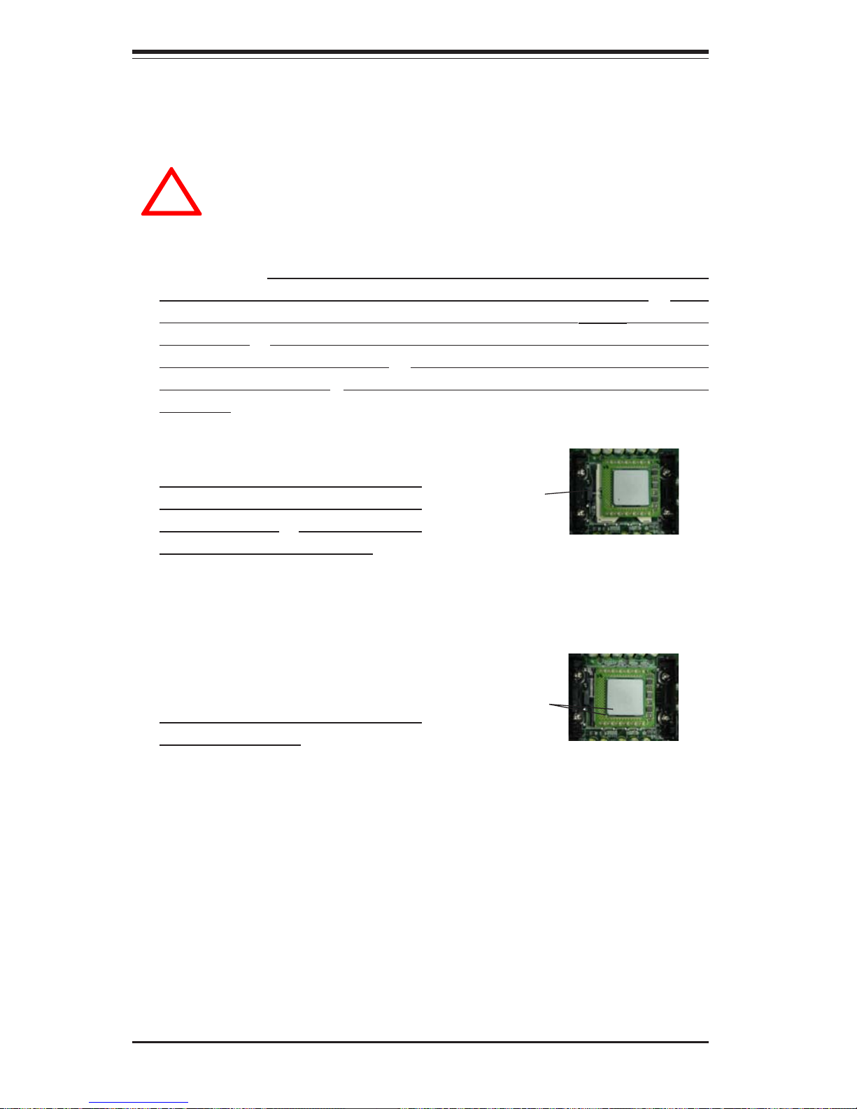
1. Lift the lever on the CPU socket.
Lift the lever completely or you will
damage the CPU socket when
power is applied. (Install a processor into CPU #1 socket first.)
2. Install the CPU in the socket.
Make sure that pin 1 of the CPU is
seated on pin 1 of the socket (both
corners are marked with a triangle).
When using only one CPU, install it
into CPU socket #1 (CPU socket #2
is automatically disabled if only one
CPU is used).
3. Press the lever down until you hear it *click* into the locked position. See
Figure 5-1 for pictures of the 604-pin CPU socket before and after the
processor is installed.
Socket lever
Pin 1
4. Apply the proper amount of thermal compound to the CPU die and place
the heatsink on top of the CPU. Make sure the heatsink sits completely flat
on the CPU. If not completely flat, the space between the two will degrade
the heat dissipation function of the heatsink, which may cause the processor to overheat.
 Loading...