

Supero SuperWorkstation 5038A-IL User Manual
SUPER
Проконсультироваться и купить данное оборудование вы можете в компании «АНД-Системс»
адрес: 125480, г.Москва, ул.Туристская, д.33/1; site: https://andpro.ru тел: +7 (495) 545-4870 email: info@andpro.ru
При обращении используйте промокод AND-PDF и получите скидку.
SuperWorkstation
5038A-IL
®
USER’S MANUAL
1.0

The information in this User’s Manual has been carefully reviewed and is believed to be accurate.
The vendor assumes no responsibility for any inaccuracies that may be contained in this document,
makes no commitment to update or to keep current the information in this manual, or to notify any
person or organization of the updates. Please Note: For the most up-to-date version of this
manual, please see our web site at www.supermicro.com.
Super Micro Computer, Inc. ("Supermicro") reserves the right to make changes to the product
described in this manual at any time and without notice. This product, including software and documentation, is the property of Supermicro and/or its licensors, and is supplied only under a license.
Any use or reproduction of this product is not allowed, except as expressly permitted by the terms
of said license.
IN NO EVENT WILL SUPERMICRO BE LIABLE FOR DIRECT, INDIRECT, SPECIAL, INCIDENTAL,
SPECULATIVE OR CONSEQUENTIAL DAMAGES ARISING FROM THE USE OR INABILITY TO
USE THIS PRODUCT OR DOCUMENTATION, EVEN IF ADVISED OF THE POSSIBILITY OF
SUCH DAMAGES. IN PARTICULAR, SUPERMICRO SHALL NOT HAVE LIABILITY FOR ANY
HARDWARE, SOFTW ARE, OR DA TA STORED OR USED WITH THE PRODUCT, INCLUDING THE
COSTS OF REPAIRING, REPLACING, INTEGRATING, INSTALLING OR RECOVERING SUCH
HARDWARE, SOFTWARE, OR DATA.
Any disputes arising between manufacturer and customer shall be governed by the laws of Santa
Clara County in the State of California, USA. The State of California, County of Santa Clara shall
be the exclusive venue for the resolution of any such disputes. Super Micro's total liability for all
claims will not exceed the price paid for the hardware product.
FCC Statement: This equipment has been tested and found to comply with the limits for a Class A
digital device pursuant to Part 15 of the FCC Rules. These limits are designed to provide reasonable
protection against harmful interference when the equipment is operated in a commercial environment. This equipment generates, uses, and can radiate radio frequency energy and, if not installed
and used in accordance with the manufacturer’s instruction manual, may cause harmful interference
with radio communications. Operation of this equipment in a residential area is likely to cause harmful
interference, in which case you will be required to correct the interference at your own expense.
California Best Management Practices Regulations for Perchlorate Materials: This Perchlorate warning applies only to products containing CR (Manganese Dioxide) Lithium coin cells. “Perchlorate
Material-special handling may apply. See www.dtsc.ca.gov/hazardouswaste/perchlorate”
WARNING: Handling of lead solder materials used in this
product may expose you to lead, a chemical known to the
State of California to cause birth defects and other reproductive harm.
Manual Revision 1.0
Release Date: June 14, 2013
Unless you request and receive written permission from Super Micro Computer, Inc., you may not
copy any part of this document.
Information in this document is subject to change without notice. Other products and companies
referred to herein are trademarks or registered trademarks of their respective companies or mark
holders.
Copyright © 2013 by Super Micro Computer, Inc.
All rights reserved.
Printed in the United States of America

Preface
About This Manual
This manual is written for professional system integrators and PC technicians. It
provides information for the installation and use of the SuperWorkstation 5038A-IL.
Installation and maintenance should be performed by experienced technicians only .
The SuperWorkstation 5038A-IL is a high-end system based on the SC732D4F500B tower chassis and the X10SAE serverboard.
Manual Organization
Preface
Chapter 1: Introduction
The fi rst chapter provides a checklist of the main components included with the
system and describes the main features of the X10SAE serverboard and the
SC732D4F-500B chassis.
Chapter 2: Installation
This chapter describes the steps necessary to setup the SuperWorkstation 5038A-IL
into a rack and check out the server confi guration prior to powering up the system. If
your system was ordered without processor and memory components, this chapter
will refer you to the appropriate sections of the manual for their installation.
Chapter 3: System Interface
Refer here for details on the system interface, which includes the functions and
information provided by the control panel on the chassis as well as other LEDs
located throughout the system.
Chapter 4: Standardized Warning Statements
You should thoroughly familiarize yourself with this chapter for a general overview
of safety precautions that should be followed when installing and servicing the
SuperWorkstation 5038A-IL.
iii

SuperWorkstation 5038A-IL User's Manual
Chapter 5: Advanced Serverboard Setup
Chapter 5 provides detailed information on the X10SAE serverboard, including the
locations and functions of connections, headers and jumpers. Refer to this chapter
when adding or removing processors or main memory and when reconfi guring the
serverboard.
Chapter 6: Advanced Chassis Setup
Refer to Chapter 6 for detailed information on the SC732D4F-500B chassis. You
should follow the procedures given in this chapter when installing, removing or
reconfi guring SAS/SATA or peripheral drives and when replacing system power
supply units and cooling fans.
Chapter 7: BIOS
The BIOS chapter includes an introduction to BIOS and provides detailed information on running the CMOS Setup Utility.
Appendix A: BIOS Error Beep Codes
Appendix B: System Specifi cations
iv

Notes
Preface
v

SuperWorkstation 5038A-IL User's Manual
Table of Contents
Chapter 1 Introduction
1-1 Overview .........................................................................................................1-1
1-2 Serverboard Features .....................................................................................1-2
Processors ......................................................................................................1-2
Memory ...........................................................................................................1-2
SATA ................................................................................................................ 1-2
PCI Expansion Slots ....................................................................................... 1-2
Onboard Controllers/Ports ..............................................................................1-2
1-3 Chassis Features ............................................................................................1-3
System Power ................................................................................................. 1-3
SATA Subsystem .............................................................................................1-3
Front Control Panel .........................................................................................1-3
Cooling System ............................................................................................... 1-3
1-4 Contacting Supermicro ....................................................................................1-5
Chapter 2 Installation
2-1 Overview .........................................................................................................2-1
2-2 Unpacking the System .................................................................................... 2-1
2-3 Warnings and Precautions .............................................................................. 2-1
2-3 Accessing the Inside of the System................................................................2-2
Chapter 3 System Interface
3-1 Overview .........................................................................................................3-1
3-2 Control Panel Button .......................................................................................3-1
Power ..............................................................................................................3-1
3-3 Communications Panel Components ..............................................................3-1
3-4 Control Panel LEDs ........................................................................................3-2
NIC ..................................................................................................................3-2
HDD .................................................................................................................3-2
Overheat/Fan Fail ........................................................................................... 3-3
3-4 Drive Carrier LEDs ..........................................................................................3-3
Chapter 4 Standardized Warning Statements for AC Systems
4-1 About Standardized Warning Statements .......................................................4-1
Warning Defi nition ...........................................................................................4-1
Installation Instructions .................................................................................... 4-4
vi

Table of Contents
Circuit Breaker ................................................................................................ 4-5
Power Disconnection Warning ........................................................................ 4-6
Equipment Installation .....................................................................................4-8
Restricted Area ................................................................................................4-9
Battery Handling ............................................................................................ 4-10
Redundant Power Supplies ..........................................................................4-12
Backplane Voltage ........................................................................................ 4-13
Comply with Local and National Electrical Codes ........................................ 4-14
Product Disposal ........................................................................................... 4-15
Hot Swap Fan Warning ................................................................................. 4-16
Power Cable and AC Adapter ......................................................................4-18
Chapter 5 Advanced Serverboard Setup
5-1 Handling the Serverboard ............................................................................... 5-1
Precautions .....................................................................................................5-1
Unpacking .......................................................................................................5-1
5-2 Connecting Cables .......................................................................................... 5-2
Connecting Data Cables ................................................................................. 5-2
Connecting Power Cables ..............................................................................5-2
Connecting the Control Panel ......................................................................... 5-2
5-3 I/O Ports ..........................................................................................................5-3
5-4 Processor and Heatsink Installation................................................................5-4
Installing an LGA 1150 Processor ................................................................... 5-4
Installing the Heatsink .....................................................................................5-6
Removing the Heatsink ................................................................................... 5-7
5-5 Installing Memory Modules ............................................................................. 5-8
Installing & Removing DIMMs ......................................................................... 5-8
5-6 Adding PCI Add-On Cards .............................................................................5-11
5-7 Serverboard Details ...................................................................................... 5-12
X10SAE Quick Reference ............................................................................. 5-12
5-8 Connector Defi nitions ................................................................................... 5-14
5-9 Jumper Settings ............................................................................................5-21
5-10 Onboard Indicators ........................................................................................5-24
5-11 SATA Ports ....................................................................................................5-24
5-12 Installing Software ......................................................................................... 5-25
SuperDoctor III .............................................................................................. 5-26
5-13 Onboard Battery ............................................................................................ 5-27
vii

SuperWorkstation 5038A-IL User's Manual
Chapter 6 Advanced Chassis Setup
6-1 Static-Sensitive Devices ..................................................................................6-1
Precautions .....................................................................................................6-1
Unpacking .......................................................................................................6-1
6-2 Accessing the Inside of the System................................................................6-2
6-3 Rotating the Hard Drive Cage.........................................................................6-3
6-4 Removing and Installing 3.5" Hard Drives ...................................................... 6-4
6-5 Removing and Installing 2.5" Hard Drives ...................................................... 6-7
6-6 Installing a 3.5" Device ................................................................................... 6-9
6-7 Installing System Fans ..................................................................................6-10
6-8 Installing the Front Bezel .............................................................................. 6-12
6-9 Power Supply ................................................................................................ 6-13
Chapter 7 BIOS
7-1 Introduction ...................................................................................................... 7-1
Starting BIOS Setup Utility .............................................................................. 7-1
How To Change the Confi guration Data .........................................................7-1
How to Start the Setup Utility .........................................................................7-2
7-2 Main Setup ...................................................................................................... 7-2
7-3 Advanced Setup Confi gurations......................................................................7-4
7-4 Event Logs .................................................................................................... 7-27
7-5 Boot Settings ................................................................................................. 7-29
7-6 Security Settings ...........................................................................................7-31
7-7 Save & Exit ................................................................................................... 7-32
Appendix A BIOS Error Beep Codes
Appendix B System Specifi cations
viii

Chapter 1: Introduction
Chapter 1
Introduction
1-1 Overview
The 5038A-IL is a high-end workstation comprised of two main subsystems: the
SC732D4F-500B tower chassis and the X10SAE single Intel® Xeon® processor
serverboard. Please refer to our web site for information on operating systems that
have been certifi ed for use with the SuperWorkstation 5038A-IL (www.supermicro.
com).
In addition to the serverboard and chassis, various hardware components have
been included with the SuperWorkstation 5038A-IL, as listed below:
• Two 12-cm PWM "SuperQuiet" chassis fans (FAN-0124L4)
Optional:
• One active CPU heatsink (SNK-P0046A4)
1-1

SuperWorkstation 5038A-IL User's Manual
1-2 Serverboard Features
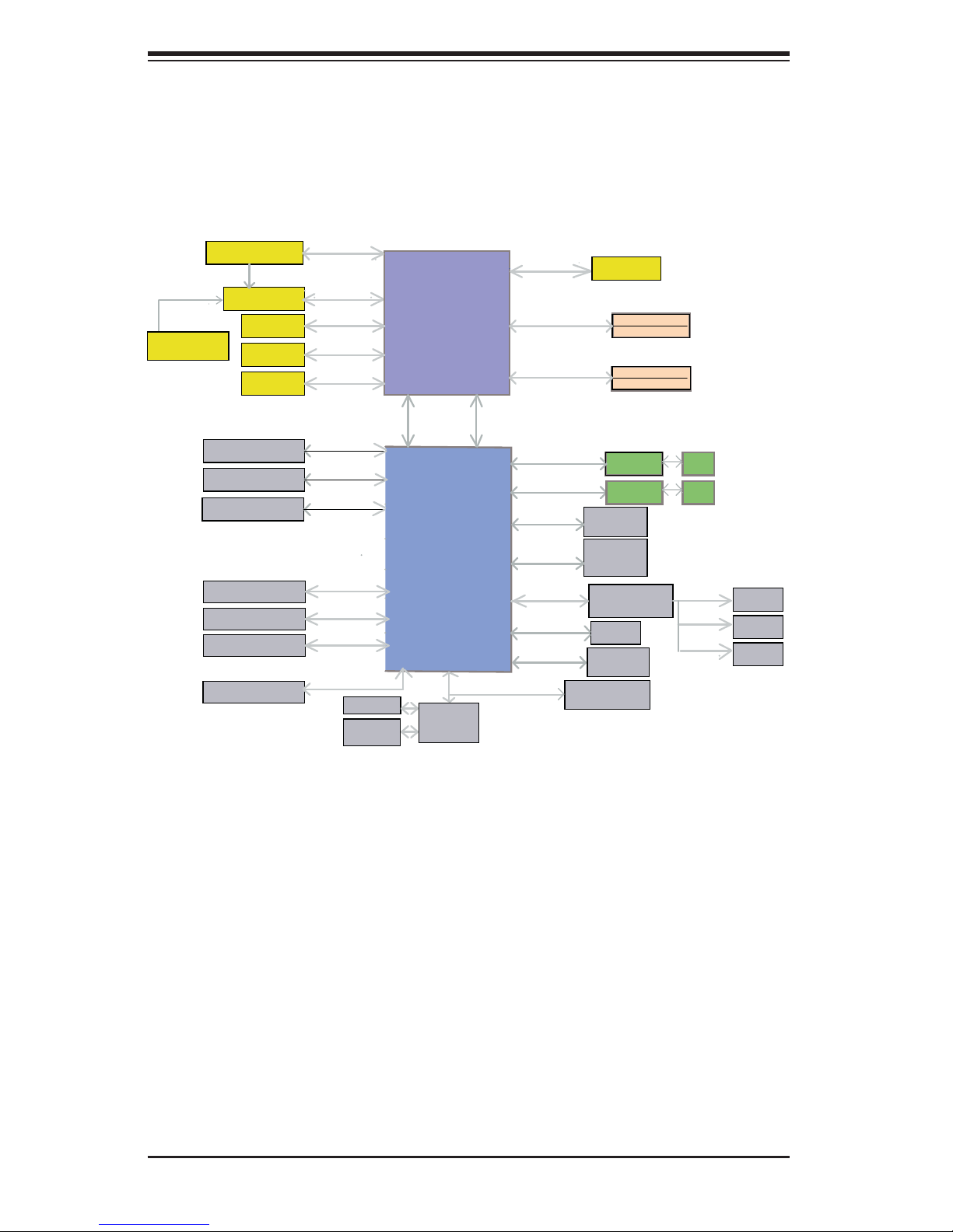
At the heart of the SuperWorkstation 5038A-IL lies the X10SAE, a single processor
serverboard based on the Intel® C226 chipset. Below are the main features of the
X10SAE. (See Figure 1-1 for a block diagram of the chipset).
Processors
The X10SAE supports a single Intel Xeon E3-1200V3 series processor or 4th Generation Intel Core™ i7/i5/i3 DT processor in an LGA1150 socket. Please refer to the
serverboard description pages on our web site for a complete listing of supported
processors (www.supermicro.com).
Memory
The X10SAE has four DIMM slots that can support up to 32 GB of Unbuffered ECC/
non-ECC DDR3-1600/1333/1066 DIMMs. See Chapter 5 for details.
SATA
A SATA controller is integrated into the chipset to provide a SATA subsystem that
supports RAID 0, 1, 5 and 10. The X10SAE supports six SATA 3.0 (RAID 0, 1, 5,
10 supported by PCH) and two additional SATA 3.0 ports (RAID 0, 1 supported by
ASM1061(R)). RAID 5 is not supported with Linux OS.
PCI Expansion Slots
The X10SAE has one PCI-E 3.0 x16, one PCI-E 3.0 x8 (in a x16 slot), three PCI-E
2.0 x1 and two PCI-32 slots.
Onboard Controllers/Ports
The rear I/O ports include a VGA port, four USB 2.0 ports, two USB 3.0 ports, a
combination PS/2 mouse/keyboard port, a DVI port, an HDMI port two Gb Ethernet
ports and six HDA (High Defi nition Audio) ports.
1-2

Chapter 1: Introduction
1-3 Chassis Features
The SC732D4F-500B is mid-tower chassis. The following is a general outline of the
main features of the chassis.
System Power
The 5038A-IL features a single 500W power supply. This power supply unit has
been designed to operate at a low noise level to make it ideal for use in a workstation environment.
SATA Subsystem
The SC732D4F-500B chass is was desi gned to su ppor t ei ght SATA h ard dr ives.
Front Control Panel
The control panel on the SuperWorkstation 5038A -IL includes system monitoring
LEDs and a main power button. In addition, two IEEE 1394a ports, two USB 2.0
ports, two USB 3.0 ports, one audio port and one microphone port are included on
the control panel. See Chapter 3 for details.
Cooling System
The SC732D4F-500B chassis has an innovative "Super Quiet" cooling design that
provides suffi cient cooling at very low noise level - ideal for a workplace environ-
ment. The chassis includes one 12-cm rear exhaust fan and an optional 12-cm
front cooling fan.
1-3
SuperWorkstation 5038A-IL User's Manual
Figure 1-1. Intel C226 Chipset:
System Block Diagram
Note: This is a general block diagram. Please see Chapter 5 for details.
PCIe x16 SLOT #6
PCIe3.0_x8
8.0GT/s
PCIe x8 SLOT #4
PCIe x1 SLOT #3
PCIe x1 SLOT #5
PCIe x1 SLOT #7
6 SATA-III PORTS
10 USB 2.0 PORTS
4 USB 3.0 PORTS
RealTEK ALC1150
PCIe3.0_x8
8.0GT/s
ASMedia Switch
ASM1480
Display Port
HDMI
DVI-D
PCIe3.0_x16
8.0GT/s
PCIe3.0_x8
8.0GT/s
PCIe2.0_x1
5GT/s
PCIe2.0_x1
5GT/s
PCIe2.0_x1
5GT/s
SATA-III
600MB/s
USB2.0
480Mbps
USB3.0
5Gbps
AZALIA
COM1/2
HEALTH
INFO
VRD12.5
INTEL LGA1150
(Socket-H3)
x4 DMI
5GT/s
x2 FDI
2.7 Gb/s
Intel
PCH
NCT6776D
LPC I/O
SVID
DDR3 (CHA)
1600/1333/1066MHz
DDR3 (CHB)
1600/1333/1066MHz
PCIe2.0_x1 GLAN1
2.5GT/s
PCIe2.0_x1 GLAN2
2.5GT/s
PCIe2.0_x1
2.5GT/s
PCIe2.0_x1
2.5GT/s
PCIe2.0_x1
2.5GT/s
Analog port A
SPI
LPC
VRM 12.5
DIMM1A (Blue)
DIMM1B (Black)
DIMM2A (Blue)
DIMM2B(Black)
i217V
i210IT
uPD720202
USB3.0 X2
ASM1061
SATA6G X2
IDT 89HMPEB383
PCIE/PCI Bridge
VGA
FLASH
SPI 128Mb
TPM1.2 (Header)
RJ45
RJ45
5V PCI
33MHz
5V PCI
33MHz
5V PCI
33MHz
PCI Slot #1
PCI Slot #2
TI 1394
1-4

1-4 Contacting Supermicro
Headquarters
Address: Super Micro Computer, Inc.
980 Rock Ave.
San Jose, CA 95131 U.S.A.
Tel: +1 (408) 503-8000
Fax: +1 (408) 503-8008
Email: marketing@supermicro.com (General Information)
support@supermicro.com (Technical Support)
Chapter 1: Introduction
Web Site:
Europe
Address: Super Micro Computer B.V.
Tel: +31 (0) 73-6400390
Fax: +31 (0) 73-6416525
Email: sales@supermicro.nl (General Information)
Asia-Pacifi c
Address: Super Micro Computer, Inc.
www.supermicro.com
Het Sterrenbeeld 28, 5215 ML
's-Hertogenbosch, The Netherlands
support@supermicro.nl (Technical Support)
rma@supermicro.nl (Customer Support)
3F, No. 150, Jian 1st Rd.
Zhonghe Dist., New Taipei City 23511
Taiwan (R.O.C)
Tel: +886-(2) 8226-3990
Fax: +886-(2) 8226-3992
Web Site:
Technical Support:
Email: support@supermicro.com.tw
Tel: +886-(2)-8226-3990
www.supermicro.com.tw
1-5

SuperWorkstation 5038A-IL User's Manual
Notes
1-6

Chapter 2: Installation
Chapter 2
Installation
2-1 Overview
This chapter provides a quick setup checklist to get your SuperWorkstation 5038A-IL
up and running. Following these steps in the order given should enable you to have
the system operational within a minimum amount of time. This quick setup assumes
that your system has come to you with the processor and memory preinstalled. If
your system is not already fully integrated with a serverboard, processor, system
memory etc., please turn to the chapter or section noted in each step for details on
installing specifi c components.
2-2 Unpacking the System
You should inspect the box the system was shipped in and note if it was damaged
in any way. If the system itself shows damage you should fi le a damage claim with
the carrier who delivered it.
Decide on a suitable location for the SuperWorkstation. It should be situated in
a clean, dust-free area that is well ventilated. Avoid areas where heat, electrical
noise and electromagnetic fi elds are generated. You will also need it placed near
a grounded power outlet. Be sure to read the Rack and Server Precautions in the
next section.
2-3 Warnings and Precautions
• Ensure that the caster wheels on the workstation are locked.
• Review the electrical and general safety precautions in Chapter 4.
• Use a regulating uninterruptible power supply (UPS) to protect the workstation
from power surges, voltage spikes and to keep your system operating in case
of a power failure.
• Allow the power supply units and hot-swap SATA drives to cool before touch-
ing them.
• To maintain proper cooling, always keep all chassis panels closed and all SATA
carriers installed when not being serviced.
2-1
SuperWorkstation 5038A-IL User's Manual
2-3 Accessing the Inside of the System
You may need to access the system periodically to perform maintenance or install
components such as hard drives. The SC732 features two removable side covers,
allowing easy access to the chassis interior.
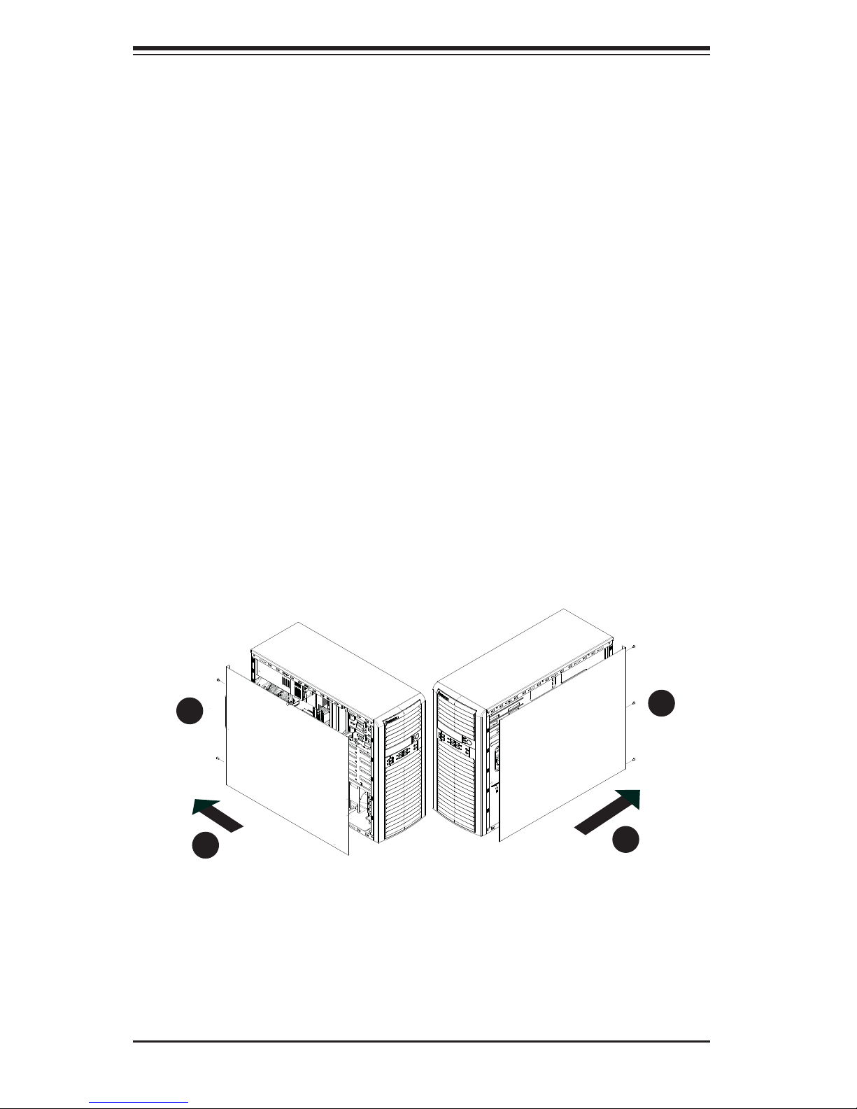
Removing the Side Covers
1. Disconnect the chassis from any power souce.
2. Remove the two screws securing the left side cover to the chassis.
3. Slide the left cover toward the rear of the chassis.
4. Lift the left cover from the chassis.
5. Remove the three screws securing the right side cover to the chassis.
6. Slide the right cover toward the rear of the chassis
7. Lift the right cover from the chassis.
Figure 2-1. Removing the Chassis Side Covers
2
2
1
3
1
5
1
6
2-2

Chapter 3: System Interface
Chapter 3
System Interface
3-1 Overview
The control panel on the 5038A-IL has several LEDs and a power button. These
LEDs keep you constantly informed of the overall status of the system and the
activity and health of specifi c components.
3-2 Control Panel Button
A single push-button is located on the front of the chassis.
Power
This is the main power button, which is used to apply or turn off the main system
power. T urning off system power with this button removes the main power but keeps
standby power supplied to the system.
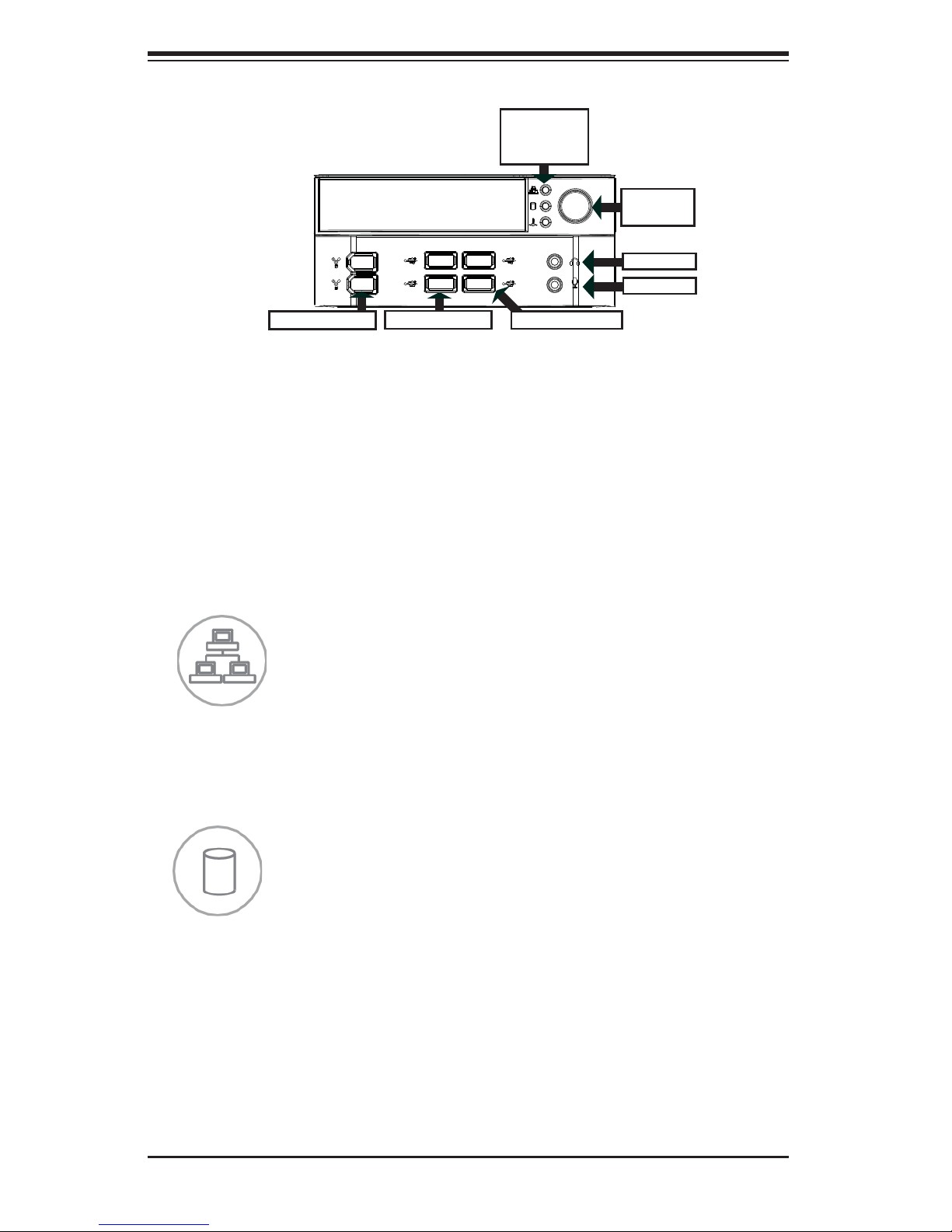
3-3 Communications Panel Components
The SC732D4F features a front communication panel allowing easy access to the
chassis communication ports. The chassis models are equipped as follows:
• Two USB 3.0 ports
• Two USB 2.0 ports
• Two IEEE 1394A ports
• One audio port
• One microphone port
See diagram on the following page.
3-1
SuperWorkstation 5038A-IL User's Manual
NIC LED
HDD LED
OH LED
Power
Button
Audio
Mic
2x 1394a
2x USB 2.0
2x USB 3.0
3-4 Control Panel LEDs
The control panel located on the front of the SC732 chassis has three LEDs. These
LEDs provide you with critical information related to different parts of the system.
This section explains what each LED indicates when illuminated and any corrective
action you may need to take.
NIC
Indicates network activity on the LAN port(s) when fl ashing.
HDD
Indicates IDE channel activity on the SAS, SATA and/or DVD-ROM drive when
fl ashing.
3-2

Chapter 3: System Interface
Overheat/Fan Fail
When this LED fl ashes, it indicates a chassis fan failure. When on continuously it
indicates an overheat condition, which may be caused by cables obstructing the
airfl ow in the system or the ambient room temperature being too warm. Check the
routing of the cables and make sure all fans are present and operating normally.
You should also check to make sure that the chassis covers are installed. Finally,
verify that the heatsinks are installed properly (see Chapter 5). This LED will remain
fl ashing or on as long as the indicated condition exists.
3-3

SuperWorkstation 5038A-IL User's Manual
Notes
3-4
Chapter 4: Warning Statements for AC Systems
Chapter 4
Standardized Warning Statements for AC Systems
4-1 About Standardized Warning Statements
The following statements are industry standard warnings, provided to warn the user
of situations which have the potential for bodily injury. Should you have questions
or experience difficulty, contact Supermicro's Technical Support department
for assistance. Only certifi ed technicians should attempt to install or confi gure
components.
Read this appendix in its entirety before installing or confi guring components in the
Supermicro chassis.
These warnings may also be found on our web site at http://www.supermicro.com/
about/policies/safety_information.cfm.
Warning Defi nition
Warning!
This warning symbol means danger. You are in a situation that could cause bodily
injury. Before you work on any equipment, be aware of the hazards involved with
electrical circuitry and be familiar with standard practices for preventing accidents.
警告の定義
この警告サインは危険を意味します。
人身事故につながる可能性がありますので、いずれの機器でも動作させる前に、
電気回路に含まれる危険性に注意して、標準的な事故防止策に精通して下さい。
此警告符号代表危险。
您正处于可能受到严重伤害的工作环境中。在您使用设备开始工作之前,必须充分
意识到触电的危险,并熟练掌握防止事故发生的标准工作程序。请根据每项警告结
尾的声明号码找到此设备的安全性警告说明的翻译文本。
此警告符號代表危險。
您正處於可能身體可能會受損傷的工作環境中。在您使用任何設備之前,請注意觸
電的危險,並且要熟悉預防事故發生的標準工作程序。請依照每一注意事項後的號
碼找到相關的翻譯說明內容。
4-1

SuperWorkstation 5038A-IL User's Manual
ןונקת תורהצהאהרהז
Warnung
WICHTIGE SICHERHEITSHINWEISE
Dieses Warnsymbol bedeutet Gefahr. Sie befi nden sich in einer Situation, die zu
Verletzungen führen kann. Machen Sie sich vor der Arbeit mit Geräten mit den
Gefahren elektrischer Schaltungen und den üblichen Verfahren zur Vorbeugung
vor Unfällen vertraut. Suchen Sie mit der am Ende jeder Warnung angegebenen
Anweisungsnummer nach der jeweiligen Übersetzung in den übersetzten
Sicherheitshinweisen, die zusammen mit diesem Gerät ausgeliefert wurden.
BEWAHREN SIE DIESE HINWEISE GUT AUF.
INSTRUCCIONES IMPORTANTES DE SEGURIDAD
Este símbolo de aviso indica peligro. Existe riesgo para su integridad física. Antes
de manipular cualquier equipo, considere los riesgos de la corriente eléctrica y
familiarícese con los procedimientos estándar de prevención de accidentes. Al
fi nal de cada advertencia encontrará el número que le ayudará a encontrar el texto
traducido en el apartado de traducciones que acompaña a este dispositivo.
GUARDE ESTAS INSTRUCCIONES.
IMPORTANTES INFORMATIONS DE SÉCURITÉ
Ce symbole d'avertissement indique un danger. Vous vous trouvez dans une
situation pouvant entraîner des blessures ou des dommages corporels. Avant
de travailler sur un équipement, soyez conscient des dangers liés aux circuits
électriques et familiarisez-vous avec les procédures couramment utilisées pour
éviter les accidents. Pour prendre connaissance des traductions des avertissements
fi gurant dans les consignes de sécurité traduites qui accompagnent cet appareil,
référez-vous au numéro de l'instruction situé à la fi n de chaque avertissement.
CONSERVEZ CES INFORMATIONS.
ןה תואבה תורהצהא ינפמ שמתשמה תא ריהזהל תנמ לע ,היישעתה ינקת יפ לע תורהז הלבח
ה וא תולאש שיו הדימב .תירשפא תיזיפי ,יהשלכ היעבב תולקתרוציל שי הכימת תקלחמ םע רשק
רידגהל וא ןיקתהל םיאשר דבלב םיכמסומ םיאנכט .ורקימרפוס לש תינכט תאה .םיביכר
תרדגה וא תנקתה ינפל ואולמב חפסנה תא
אורקל שי .ורקימרפוס יזראמב םיביכרה
4-2

Warning Statements for AC Systems
. ﻲﻓ ﻚﻧﺍ ﻥﺃ ﻦﻜﻤﻳ ﺔﻟﺎﺣ ﻲﻓ ﺐﺒﺴﺘﺗ ﺔﺑﺎﺻﺍ ﺔﻳﺪﺴﺟ ﺰﻣﺮﻟﺍ ﺍﺬﻫ ﻲﻨﻌﻳ ﺮﻄﺧ !ﺮﻳﺬﺤﺗ
ﻥﺃ ﻞﺒﻗ ﻱﺃ ﻰﻠﻋ ﻞﻤﻌﺗ ﺕﺍﺪﻌﻣ،ﻛﻢﻠﻋ ﻰﻠﻋ ﻦ ﻦﻋ ﺔﻤﺟﺎﻨﻟﺍ ﺮﻁﺎﺨﻤﻟﺎﺑ ﺮﺋﺍﻭﺪﻟﺍ
ﺔﻴﺋﺎﺑﺮﻬﻜﻟﺍ
ﻛﻭﺔﻳﺍﺭﺩ ﻰﻠﻋ ﻦ ﺭﺎﻤﻤﻟﺎﺑﺕﺎﺳ ﺔﻴﺋﺎﻗﻮﻟﺍ ﻟ ﻊﻨﻤﻉﻮﻗﻭ ﻱﺃﺙﺩﺍﻮﺣ
ﻢﻗﺭ ﻡﺪﺨﺘﺳﺍ ﻥﺎﻴﺒﻟﺍ ﺹﻮﺼﻨﻤﻟﺍ ﺔﻳﺎﻬﻧ ﻲﻓ ﺮﻳﺬﺤﺗ ﻞﻛ ﺭﻮﺜﻌﻠﻟ ﺎﻬﺘﻤﺟﺮﺗ
안전을 위한 주의사항
경고!
이 경고 기호는 위험이 있음을 알려 줍니다. 작업자의 신체에 부상을 야기 할 수
있는 상태에 있게 됩니다. 모든 장비에 대한 작업을 수행하기 전에 전기회로와
관련된 위험요소들을 확인하시고 사전에 사고를 방지할 수 있도록 표준
작업절차를 준수해 주시기 바랍니다.
해당 번역문을 찾기 위해 각 경고의 마지막 부분에 제공된 경고문 번호를
참조하십시오
BELANGRIJKE VEILIGHEIDSINSTRUCTIES
Dit waarschuwings symbool betekent gevaar. U verkeert in een situatie die
lichamelijk letsel kan veroorzaken. Voordat u aan enige apparatuur gaat werken,
dient u zich bewust te zijn van de bij een elektrische installatie betrokken risico's
en dient u op de hoogte te zijn van de standaard procedures om ongelukken te
voorkomen. Gebruik de nummers aan het eind van elke waarschuwing om deze te
herleiden naar de desbetreffende locatie.
BEWAAR DEZE INSTRUCTIES
4-3

SuperWorkstation 5038A-IL User's Manual
Installation Instructions
Warning!
Read the installation instructions before connecting the system to the power source.
設置手順書
システムを電源に接続する前に、設置手順書をお読み下さい。
警告
将此系统连接电源前,请先阅读安装说明。
警告
將系統與電源連接前,請先閱讀安裝說明。
Warnung
Vor dem Anschließen des Systems an die Stromquelle die Installationsanweisungen
lesen.
¡Advertencia!
Lea las instrucciones de instalación antes de conectar el sistema a la red de
alimentación.
Attention
Avant de brancher le système sur la source d'alimentation, consulter les directives
d'installation.
אורקל שי רוקמל תכרעמה רוביח ינפל הנקתה תוארוה תאחתמ.
ﻟﺍ ﺕﺍﺩﺎﺷﺭﺇ ﺮﻗﺍﺐﻴﻛﺮﺘ ﻞﻴﺻﻮﺗ ﻞﺒﻗ ﻰﻟﺇ ﻡﺎﻈﻨﻟﺍ ﺔﻗﺎﻄﻠﻟ ﺭﺪﺼﻣ
시스템을 전원에 연결하기 전에 설치 안내를 읽어주십시오.
Waarschuwing
Raadpleeg de installatie-instructies voordat u het systeem op de voedingsbron
aansluit.
4-4
Chapter 4: Warning Statements for AC Systems
Circuit Breaker
Warning!
This product relies on the building's installation for short-circuit (overcurrent)
protection. Ensure that the protective device is rated not greater than: 250 V, 20 A.
サーキット・ブレーカー
この製 品 は、短絡(過電流)保護装置がある建物での設置を前提としています。
保護装置の定格が250V、20Aを超えないことを確認下さい。
警告
此产品的短路(过载电流)保护由建筑物的供电系统提供,确保短路保护设备的额定电
流不大于250V,20A。
警告
此產品的短路(過載電流)保護由建築物的供電系統提供,確保短路保護設備的額定電
流不大於250V,20A。
Warnung
Dieses Produkt ist darauf angewiesen, dass im Gebäude ein Kurzschluss-
bzw. Überstromschutz installiert ist. Stellen Sie sicher, dass der Nennwert der
Schutzvorrichtung nicht mehr als: 250 V, 20 A beträgt.
¡Advertencia!
Este equipo utiliza el sistema de protección contra cortocircuitos (o sobrecorrientes)
del edifi cio. Asegúrese de que el dispositivo de protección no sea superior a: 250
V, 20 A.
Attention
Pour ce qui est de la protection contre les courts-circuits (surtension), ce produit
dépend de l'installation électrique du local. Vérifi ez que le courant nominal du
dispositif de protection n'est pas supérieur à :250 V, 20 A.
ﺞﺘﻨﻤﻟﺍ ﺍﺬﻫ ﻰﻠﻋ ﺪﻤﺘﻌﻳ ﺕﺍﺪﻌﻣ ﺔﻳﺎﻤﺤﻟﺍ ﺓﺮﻴﺼﻘﻟﺍﺮﺋﺍﻭﺪﻟﺍ ﻦﻣ ﺎﻬﺘﻴﺒﺜﺗ ﻢﺗ ﻲﺘﻟﺍ ﻲﻓ
לע ךמתסמ הז רצומנגהה תעינמל םינבמב תנקתומה יכ אדוול שי .ילמשח רצק
רצקה ינפמ ןגמה רישכמה ילמשחהמ רתוי אל אוה-250 V, 20 A
ﻰﻨﺒﻤﻟﺍ
20A, 250V : ﻦﻣ ﺪﻛﺄﺗ ﻥﺃ ﻢﻴﻴﻘﺗ ﺯﺎﻬﺠﻟﺍ ﻟﺍﻲﺋﺎﻗﻮ ﺲﻴﻟ ﻦﻣ ﺮﺜﻛﺃ
4-5
SuperWorkstation 5038A-IL User's Manual
경고!
이 제품은 전원의 단락(과전류)방지에 대해서 전적으로 건물의 관련 설비에
의존합니다. 보호장치의 정격이 반드시 250V(볼트), 20A(암페어)를 초과하지
않도록 해야 합니다.
Waarschuwing
Dit product is afhankelijk van de kortsluitbeveiliging (overspanning) van
uw electrische installatie. Controleer of het beveiligde aparaat niet groter
gedimensioneerd is dan 220V, 20A.
Power Disconnection Warning
Warning!
The system must be disconnected from all sources of power and the power cord
removed from the power supply module(s) before accessing the chassis interior to
install or remove system components.
電源切断の警告
システムコンポーネントの取り付けまたは取り外しのために、シャーシー内部にアクセス
するには、
システムの電源はすべてのソースから切断され、電源コードは電源モジュールから取り
外す必要があります。
警告
在你打开机箱并安装或移除内部器件前,必须将系统完全断电,并移除电源线。
警告
在您打開機殼安裝或移除內部元件前,必須將系統完全斷電,並移除電源線。
Warnung
Das System muss von allen Quellen der Energie und vom Netzanschlusskabel
getrennt sein, das von den Spg.Versorgungsteilmodulen entfernt wird, bevor es
auf den Chassisinnenraum zurückgreift, um Systemsbestandteile anzubringen oder
zu entfernen.
4-6

Chapter 4: Warning Statements for AC Systems
ילמשח קותינ ינפמ הרהזא
!הרהזא
¡Advertencia!
El sistema debe ser disconnected de todas las fuentes de energía y del cable
eléctrico quitado de los módulos de fuente de alimentación antes de tener acceso
el interior del chasis para instalar o para quitar componentes de sistema.
Attention
Le système doit être débranché de toutes les sources de puissance ainsi que de
son cordon d'alimentation secteur avant d'accéder à l'intérieur du chassis pour
installer ou enlever des composants de systéme.
למשחה תורוקמ לכמ תכרעמה תא קתנל שי ריסהל שיו קפסהמ ילמשחה לבכ תא
נקתה ךרוצל זראמה לש ימינפה קלחל השיג ינפלת רסה ואת .םיביכר
ﻞﺼﻓ ﺐﺠﻳ ﻡﺎﻈﻨﻟﺍ ﻊﻴﻤﺟ ﻦﻣﺭﺩﺎﺼﻣ ﺔﻗﺎﻄﻟﺍ ﺔﻟﺍﺯﺇﻭ ءﺎﺑﺮﻬﻜﻟﺍ ﻚﻠﺳ ﻦﻣ ﺓﺪﺣﻭ ﺩﺍﺪﻣﺍ
ﺔﻗﺎﻄﻟﺍ ﻞﺒﻗ
ﺯﺎﻬﺠﻟﺍ
경고!
시스템에 부품들을 장착하거나 제거하기 위해서는 섀시 내부에 접근하기 전에
반드시 전원 공급장치로부터 연결되어있는 모든 전원과 전기코드를 분리해주어야
합니다.
Waarschuwing
Voordat u toegang neemt tot het binnenwerk van de behuizing voor het installeren
of verwijderen van systeem onderdelen, dient u alle spanningsbronnen en alle
stroomkabels aangesloten op de voeding(en) van de behuizing te verwijderen
ﻰﻟﺇ ﻝﻮﺻﻮﻟﺍ ﺔﻴﻠﺧﺍﺪﻟﺍ ﻖﻁﺎﻨﻤﻟﺍ ﻟﻞﻜﻴﻬﻠ ﺔﻟﺍﺯﺇ ﻭﺃ ﺖﻴﺒﺜﺘﻟ ﺕﺎﻧﻮﻜﻣ
4-7

SuperWorkstation 5038A-IL User's Manual
Equipment Installation
Warning!
Only trained and qualifi ed personnel should be allowed to install, replace, or service
this equipment.
機器の設置
トレーニングを受け認定された人だけがこの装置の設置、交換、またはサービスを許可
されています。
警告
只有经过培训且具有资格的人员才能进行此设备的安装、更换和维修。
警告
只有經過受訓且具資格人員才可安裝、更換與維修此設備。
Warnung
Das Installieren, Ersetzen oder Bedienen dieser Ausrüstung sollte nur geschultem,
qualifi ziertem Personal gestattet werden.
¡Advertencia!
Solamente el personal califi cado debe instalar, reemplazar o utilizar este equipo.
Attention
Il est vivement recommandé de confier l'installation, le remplacement et la
maintenance de ces équipements à des personnels qualifi és et expérimentés.
!הרהזא
שר דבלב ךמסומ תווצתא ףילחהל ,ןיקתהל יא .דויצה רובע תוריש תתל וא דויצה
ﻦﻴﺑﺭﺪﻤﻟﺍﻭ ﻭ ﺐﻴﻛﺮﺘﻟﻝﺍﺪﺒﺘﺳﺍ ﻭﺃ ﺔﻣﺪﺧ ﺯﺎﻬﺠﻟﺍ ﺍﺬﻫ ﺢﻤﺴﻳ ﻥﺃ ﺐﺠﻳ ﻂﻘﻓ ﻦﻴﻠﻫﺆﻤﻟﺍ ﻦﻴﻔﻅﻮﻤﻠﻟ
경고!
훈련을 받고 공인된 기술자만이 이 장비의 설치, 교체 또는 서비스를 수행할 수
있습니다.
4-8
Chapter 4: Warning Statements for AC Systems
Waarschuwing
Deze apparatuur mag alleen worden geïnstalleerd, vervangen of hersteld door
geschoold en gekwalifi ceerd personeel.
Restricted Area
Warning!
This unit is intended for installation in restricted access areas. A restricted access
area can be accessed only through the use of a special tool, lock and key, or other
means of security. (This warning does not apply to workstations).
アクセス制限区域
このユ ニットは 、アクセス制限区域に設置されることを想定しています。
アクセス制限区域は、特別なツール、鍵と錠 前、その他のセキュリティの手段を用いての
み出入りが可能です。
警告
此部件应安装在限制进出的场所,限制进出的场所指只能通过使用特殊工具、锁和
钥匙或其它安全手段进出的场所。
警告
此裝置僅限安裝於進出管制區域,進出管制區域係指僅能以特殊工具、鎖頭及鑰匙
或其他安全方式才能進入的區域。
Warnung
Diese Einheit ist zur Installation in Bereichen mit beschränktem Zutritt vorgesehen.
Der Zutritt zu derartigen Bereichen ist nur mit einem Spezialwerkzeug, Schloss und
Schlüssel oder einer sonstigen Sicherheitsvorkehrung möglich.
¡Advertencia!
Esta unidad ha sido diseñada para instalación en áreas de acceso restringido.
Sólo puede obtenerse acceso a una de estas áreas mediante la utilización de una
herramienta especial, cerradura con llave u otro medio de seguridad.
Attention
Cet appareil doit être installée dans des zones d'accès réservés. L'accès à une
zone d'accès réservé n'est possible qu'en utilisant un outil spécial, un mécanisme
de verrouillage et une clé, ou tout autre moyen de sécurité.
4-9
SuperWorkstation 5038A-IL User's Manual
תלבגומ השיג םע רוזא
!הרהזא
תרזעב תנתינ השיגה .השיג תלבגה םהב שיש םירוזאב הדיחיה תא ןיקתהל שי
.('דכו לוענמ ,חתפמ) דבלב החטבא ילכ
. ﺺﻴﺼﺨﺗ ﺓﺪﺣﻮﻟﺍ ﻩﺬﻫ ﻲﻓ ﺎﻬﺒﻴﻛﺮﺘﻟ ﻖﻁﺎﻨﻣ ﺓﺭﻮﻈﺤﻣ ﻢﺗ
ﺻﻮﻟﺍ ﻦﻜﻤﻳﻰﻟﺇ ﻝﻮ ﺔﻘﻄﻨﻣ ﺓﺭﻮﻈﺤﻣ ﻂﻘﻓ ﻡﺍﺪﺨﺘﺳﺍ ﻝﻼﺧ ﻦﻣ ،ﺔﺻﺎﺧ ﺓﺍﺩﺃ
ﻭﺃ ﻱﺃ ﻼﻟ ﻯﺮﺧﺃ ﺔﻠﻴﺳﻭﻥﺎﻣﻷ ﺡﺎﺘﻔﻣﻭ ﻞﻔﻗ
경고!
이 장치는 접근이 제한된 구역에 설치하도록 되어있습니다. 특수도구, 잠금 장치 및
키, 또는 기타 보안 수단을 통해서만 접근 제한 구역에 들어갈 수 있습니다.
Waarschuwing
Dit apparaat is bedoeld voor installatie in gebieden met een beperkte toegang.
Toegang tot dergelijke gebieden kunnen alleen verkregen worden door gebruik te
maken van speciaal gereedschap, slot en sleutel of andere veiligheidsmaatregelen.
Battery Handling
Warning!
There is the danger of explosion if the battery is replaced incorrectly. Replace the
battery only with the same or equivalent type recommended by the manufacturer.
Dispose of used batteries according to the manufacturer's instructions
電池の取り扱い
電池交換が正しく行われなかった場合、破裂の危険性があります。交換する電池はメー
カーが推奨する型、または 同等のものを使用 下さい。使用済電池は製造元の指示に従
って処 分して 下さい。
警告
电池更换不当会有爆炸危险。请只使用同类电池或制造商推荐的功能相当的电池更
换原有电池。请按制造商的说明处理废旧电池。
警告
電池更換不當會有爆炸危險。請使用製造商建議之相同或功能相當的電池更換原有
電池。請按照製造商的說明指示處理廢棄舊電池。
4-10
 Loading...