

Supero SuperWorkstation 5037A-I User Manual
®
SuperWorkstation
5037A-I
SUPER
USER’S MANUAL
1.0

The information in this User’s Manual has been carefully reviewed and is believed to be accurate.
The vendor assumes no responsibility for any inaccuracies that may be contained in this document,
makes no commitment to update or to keep current the information in this manual, or to notify any
person or organization of the updates. Please Note: For the most up-to-date version of this
manual, please see our web site at www.supermicro.com.
Super Micro Computer, Inc. ("Supermicro") reserves the right to make changes to the product
described in this manual at any time and without notice. This product, including software and documentation, is the property of Supermicro and/or its licensors, and is supplied only under a license.
Any use or reproduction of this product is not allowed, except as expressly permitted by the terms
of said license.
IN NO EVENT WILL SUPERMICRO BE LIABLE FOR DIRECT, INDIRECT, SPECIAL, INCIDENTAL,
SPECULATIVE OR CONSEQUENTIAL DAMAGES ARISING FROM THE USE OR INABILITY TO
USE THIS PRODUCT OR DOCUMENTATION, EVEN IF ADVISED OF THE POSSIBILITY OF
SUCH DAMAGES. IN PARTICULAR, SUPERMICRO SHALL NOT HAVE LIABILITY FOR ANY
HARDWARE, SOFTWARE, OR DATA STORED OR USED WITH THE PRODUCT, INCLUDING THE
COSTS OF REPAIRING, REPLACING, INTEGRATING, INSTALLING OR RECOVERING SUCH
HARDWARE, SOFTWARE, OR DATA.
Any disputes arising between manufacturer and customer shall be governed by the laws of Santa
Clara County in the State of California, USA. The State of California, County of Santa Clara shall
be the exclusive venue for the resolution of any such disputes. Super Micro's total liability for all
claims will not exceed the price paid for the hardware product.
FCC Statement: This equipment has been tested and found to comply with the limits for a Class A
digital device pursuant to Part 15 of the FCC Rules. These limits are designed to provide reasonable
protection against harmful interference when the equipment is operated in a commercial environment. This equipment generates, uses, and can radiate radio frequency energy and, if not installed
and used in accordance with the manufacturer’s instruction manual, may cause harmful interference
with radio communications. Operation of this equipment in a residential area is likely to cause harmful interference, in which case you will be required to correct the interference at your own expense.
California Best Management Practices Regulations for Perchlorate Materials: This Perchlorate warning applies only to products containing CR (Manganese Dioxide) Lithium coin cells. “Perchlorate
Material-special handling may apply. See www.dtsc.ca.gov/hazardouswaste/perchlorate”
WARNING: Handling of lead solder materials used in this
product may expose you to lead, a chemical known to the
State of California to cause birth defects and other reproductive harm.
Manual Revision 1.0
Release Date: August 3, 2012
Unless you request and receive written permission from Super Micro Computer, Inc., you may not
copy any part of this document.
Information in this document is subject to change without notice. Other products and companies
referred to herein are trademarks or registered trademarks of their respective companies or mark
holders.
Copyright © 2012 by Super Micro Computer, Inc.
All rights reserved.
Printed in the United States of America

iii
Preface
Preface
About This Manual
This manual is written for professional system integrators and PC technicians. It
provides information for the installation and use of the SuperWorkstation 5037A-I.
Installation and maintenance should be performed by experienced technicians only.
The SuperWorkstation 5037A-I is a high-end system based on the SC732D4-903B
mid-tower chassis and the X9SRA motherboard.
Manual Organization
Chapter 1: Introduction
The rst chapter provides a list of the main components included with the system
and describes the main features of the X9SRA motherboard and the SC732D4-
903B chassis.
Chapter 2: Server Installation
This chapter describes the steps necessary to set up the SuperWorkstation 5037A-I
and to check out the server conguration prior to powering-up the system. If your
system was ordered without processor and memory components, this chapter will
refer you to the appropriate sections of the manual for their installation.
Chapter 3: System Interface
Refer here for details on the system interface, which includes the functions and
information provided by the control panel on the chassis as well as other LEDs
located throughout the system.
Chapter 4: System Safety
You should thoroughly familiarize yourself with this chapter for a general overview
of safety precautions that should be followed when installing and servicing the
SuperWorkstation 5037A-I.

SuperWorkstation 5037A-I User's Manual
iv
Chapter 5: Advanced Motherboard Setup
Chapter 5 provides detailed information on the X9SRA motherboard, including the
locations and functions of connections, headers and jumpers. Refer to this chapter
when adding or removing processors or main memory and when reconguring the
motherboard.
Chapter 6: Advanced Chassis Setup
Refer to Chapter 6 for detailed information on the SC732D4-903B chassis. You
should follow the procedures given in this chapter when installing, removing or
reconguring SATA or peripheral drives and when replacing system power supply
units and cooling fans.
Chapter 7: BIOS
The BIOS chapter includes an introduction to BIOS and provides detailed informa-
tion on running the CMOS Setup Utility.
Appendix A: BIOS Error Beep Codes
Appendix B: UEFI BIOS Recovery Instructions
Appendix C: System Specications

v
Preface
Notes

vi
SuperWorkstation 5037A-I User's Manual
Table of Contents
Chapter 1 Introduction
1-1 Overview ......................................................................................................... 1-1
1-2 Motherboard Features ..................................................................................... 1-2
Processors ...................................................................................................... 1-2
Memory ........................................................................................................... 1-2
SATA .............................................................................................................. 1-2
PCI Expansion Slots ....................................................................................... 1-2
Onboard Controllers/Ports .............................................................................. 1-2
1-3 Chassis Features ............................................................................................ 1-2
System Power ................................................................................................. 1-3
SATA Support .................................................................................................. 1-3
Front Control Panel ......................................................................................... 1-3
Cooling System ............................................................................................... 1-3
Contacting Supermicro .................................................................................... 1-5
Chapter 2 Installation
2-1 Overview ......................................................................................................... 2-1
2-2 Unpacking the System .................................................................................... 2-1
2-3 Preparing for Setup ......................................................................................... 2-1
Choosing a Setup Location ............................................................................. 2-2
Server Cautions .............................................................................................. 2-2
Chapter 3 System Interface
3-1 Overview ......................................................................................................... 3-1
3-2 Control Panel Buttons ..................................................................................... 3-1
Power .............................................................................................................. 3-1
Reset ............................................................................................................... 3-1
3-3 Control Panel LEDs ........................................................................................ 3-2
Chapter 4 System Safety
4-1 Electrical Safety Precautions .......................................................................... 4-1
4-2 General Safety Precautions ............................................................................ 4-2
4-3 ESD Precautions ............................................................................................. 4-3
4-4 Operating Precautions .................................................................................... 4-4
Chapter 5 Advanced Motherboard Setup
5-1 Handling the Motherboard .............................................................................. 5-1

vii
Table of Contents
Cautions .......................................................................................................... 5-1
Unpacking ....................................................................................................... 5-2
5-2 Motherboard Installation .................................................................................. 5-2
5-3 Connecting Cables .......................................................................................... 5-3
Connecting Data Cables ................................................................................. 5-3
Connecting Power Cables .............................................................................. 5-3
Connecting the Control Panel ......................................................................... 5-3
5-4 I/O Ports .......................................................................................................... 5-4
5-5 Processor and Heatsink Installation................................................................ 5-5
Installing an LGA 2011 Processor ................................................................... 5-5
Installing a CPU Heatsink ............................................................................... 5-8
Removing the Heatsink ................................................................................... 5-9
5-6 Installing Memory Modules ........................................................................... 5-10
Installing and Removing DIMMs ................................................................... 5-10
5-7 Adding PCI Add-On Cards ............................................................................ 5-12
5-8 Motherboard Details ...................................................................................... 5-13
5-9 Connector Denitions ................................................................................... 5-15
5-10 Jumper Settings ............................................................................................ 5-22
5-11 Onboard Indicators ........................................................................................ 5-25
5-12 SATA Ports .................................................................................................... 5-26
5-13 Installing Software ......................................................................................... 5-27
SuperDoctor III .............................................................................................. 5-28
5-14 Motherboard Battery ..................................................................................... 5-30
Chapter 6 Advanced Chassis Setup
6-1 Static-Sensitive Devices .................................................................................. 6-1
Cautions .......................................................................................................... 6-1
Unpacking ....................................................................................................... 6-1
Installation Instructions .................................................................................... 6-2
6-2 Removing the Power Cord .............................................................................. 6-2
6-3 Front Control Panel ......................................................................................... 6-4
6-4 Removing the Chassis Side Covers ............................................................... 6-5
6-5 System Fans ................................................................................................... 6-6
Fan Failure ...................................................................................................... 6-6
Replacing Chassis Cooling Fans .................................................................... 6-6
6-6 Drive Installation .............................................................................................. 6-8

viii
SuperWorkstation 5037A-I User's Manual
6-7 Removing and Installing Optional 2.5" Hard Drives ......................................6-11
6-8 Power Supply ............................................................................................... 6-13
Chapter 7 BIOS
7-1 Introduction ...................................................................................................... 7-1
Starting BIOS Setup Utility .............................................................................. 7-1
How To Change the Conguration Data ......................................................... 7-1
How to Start the Setup Utility ......................................................................... 7-2
7-2 Main Setup ...................................................................................................... 7-2
7-3 Advanced Setup Congurations...................................................................... 7-4
7-4 Event Logs .................................................................................................... 7-20
7-5 Security Settings ........................................................................................... 7-22
7-6 Boot ............................................................................................................... 7-23
7-7 Save & Exit ................................................................................................... 7-24
Appendix A BIOS Error Beep Codes
Appendix B UEFI BIOS Recovery Instructions
Appendix C System Specications

Chapter 1
Introduction
1-1 Overview
The 5037A-I is a high-end workstation comprised of two main subsystems: the
SC732D4-903B mid-tower/4U chassis and the X9SRA Intel® Xeon® processor
motherboard. Please refer to our web site for information on operating systems that
have been certied for use with the SuperWorkstation 5037A-I (www.supermicro.
com). In addition to the motherboard and chassis, various hardware components
have been included with the SuperWorkstation 5037A-I, as listed below:
One (1) Rackmount kit (MCP-290-00053-0N)
•One 12 cm exhaust fan (FAN-0124L4)
•SATA Accessories
Four 3.5" SATA HDD bays in a 90° rotating hard drive cage
•Optional:
Four 2.5" HDD/SSD drives
SATA cable (CBL-179L)
DVD-ROM drive
Active CPU heatsinks (SNK-P0050AP4)
SATA power adapter (CBL-0082L)
Black 5.25" LCD tray, supports 1x 3.5" HDD (MCP-220-00095OB
HDD/SDD drive cage (MCP-220-73201-ON) supporting four 2.5" HDDs.
Active CPU heatsink (SNK-P0050AP4)
DVD-ROM drive
SATA cable (CBL-179L)
SATA power adapter (CBL-0082L)
One 12 cm "Whisper Quiet" system cooling fan
Chapter 1: Introduction
1-1

SuperWorkstation 5037A-I User's Manual
1-2
1-2 Motherboard Features
At the heart of the SuperWorkstation 5037A-I lies the X9SRA, a single processor
motherboard based on the Intel® C600 series chipset. Below are the main features
of the X9SRA. (See Figure 1-1 for a block diagram of the chipset).
Processors
The X9SRA supports an Intel E5-1600/E5-2600 series processor (2011-pin Socket
R). Please refer to the motherboard description pages on our Web site for a com-
plete listing of supported processors (www.supermicro.com).
Memory
The X9SRA features up to 256GB RDIMM or 64GB UDIMM; DDR3 up to 1600MHz
See Chapter 5 for details.
SATA
A SATA controller is integrated into the chipset to provide a Serial ATA subsystem.
The 5037A-I (X9SRA) supports two SATA 3.0 and eight SATA 2.0 ports.
PCI Expansion Slots
The X9SRA has features the following PCI expansion slots:
Two (2) PCI-Express 3.0 x16 Slot, one (1) PCI-Express 3.0 x4 in x8 Slot, one (1)
PCI-Express 2.0 x4 in x8 Slot and one (1) PCI 33MHz Slot.
Onboard Controllers/Ports
The color-coded I/O ports include eight (8) USB 2.0 ports on the rear I/O panel
Six (6) USB 2.0 headers for front panel access, two (2) USB 3.0 (5Gb/s) headers
for front panel access, two (2) USB 3.0 (5Gb/s) ports on the rear I/O panel PS/2
mouse and keyboard ports, two (2) Fast UART 16550 connections on two headers
(COM1 & COM2).
1-3 Chassis Features
The 5037A-I is a mid-tower chassis with Whisper Quiet operation. The following is
a general outline of the main features of the SC743D2-903B chassis.

1-3
Chapter 1: Introduction
System Power
The 5037A-I features a single 900W Gold Level multi-outlet power supply with
PMBus, ideal for use in a workstation environment.
SATA Support
The SC732D4-903B chassis was designed to support four 3.5" SATA hard drives
and four optional 2.5" hard drives.
Front Control Panel
The control panel on the 5037A-I provides you with system monitoring and control.
LEDs indicate system power, HDD activity, network activity, overheat conditions
and power supply failure. A main power button and a system reset button are also
included.
Note: The power supply fail LED indicates the power supply fan has failed.
Cooling System
The SC732D4-903B chassis has an innovative "Whisper Quiet" cooling design
that provides sufcient cooling at very low noise level - ideal for a workplace en-
vironment. The chassis includes one 12-cm exhaust fan located at the rear of the
chassis, and one 12-cm optional system cooling fan in the middle of the chassis.
The power supply has one internal fan for redundancy; if this fan fails, the power
supply must be replaced. See details in Chapter 6.
SuperWorkstation 5037A-I User's Manual
1-4
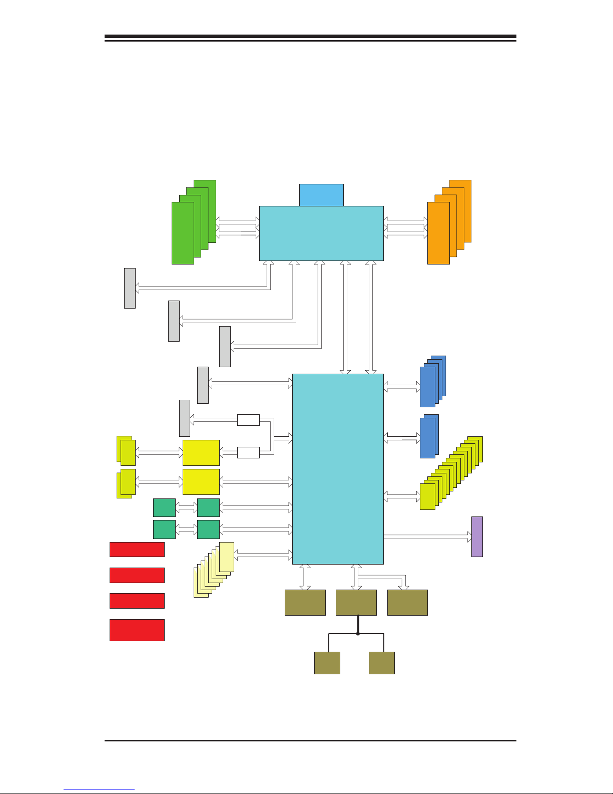
Figure 1-1. Intel C600 Chipset:
System Block Diagram
Note: This is a general block diagram. Please see Chapter 5 for details.
SLOT 1
SLOT 6
#8
COM1
Header
6 PHASE
PCI-E X16
X9SRA
800/1066/1333
PCI-E X8
PCI 32Bit/33MHz
SLOT 2
PCI-E X16 G3
VR12
PCI-E X4 G3
#0-4
#0-3
#5
SLOT 5
#0-2
PCI-E X1 G2
PCI-E X1
#0-8
#0-7
uPD720200
#0-6
LAN1
82579
PCI-E X1 G2
PCI-E X1 G2
#6
#7
LAN2
82574
PCI-E X1 G2
#8
RJ45
RJ45
USB 3.0
#14
#15
#1/2/3/4
#6
#7
COM2
Header
SLOT 4
USB 2.0
6.0 Gb/S
Sandybridge-EP
PCH
PATSBURG
SSB-D
PCI-E X16 G3
BIOS
SIO
NCT6776F
LPC
#0
#5
#0
#1
FRONT PANEL
SYSTEM POWER
DEBUG
PORT
FAN SPEED
CTRL
8 Rear
6 Front
PCI-E X4 G2
#9
#10
PCI-E X8
#4
#5
3.0 Gb/S
#2
#3
3.0 Gb/S
PCI-E X16
#0
#1
#2
#3
#4
#5
#6
#7
DMI2 4GB/s
DMI2
8 SNB CORE
DDR-III
0 Ohm
0 Ohm
uPD720201
#16
#17
USB 3.0
SPI
TPM
HEADER
PCI-E X4 G3
SLOT 3
#2 #3 #1B #1A
PCI 33M
#4
#11
#12
#13
800/1066/1333
#0-1
DDRIII
SATASATA
DDRIII
#0-5
USB
#1
#2
#3
USBUSB
SAS

1-5
Chapter 1: Introduction
Contacting Supermicro
Headquarters
Address: Super Micro Computer, Inc.
980 Rock Ave.
San Jose, CA 95131 U.S.A.
Tel: +1 (408) 503-8000
Fax: +1 (408) 503-8008
Email: marketing@supermicro.com (General Information)
support@supermicro.com (Technical Support)
Web Site: www.supermicro.com
Europe
Address: Super Micro Computer B.V.
Het Sterrenbeeld 28, 5215 ML
's-Hertogenbosch, The Netherlands
Tel: +31 (0) 73-6400390
Fax: +31 (0) 73-6416525
Email: sales@supermicro.nl (General Information)
support@supermicro.nl (Technical Support)
rma@supermicro.nl (Customer Support)
Asia-Pacic
Address: Super Micro Computer, Inc.
4F, No. 232-1, Liancheng Rd
New Taipei City 235
Taiwan
Tel: +886-(2) 8226-5990
Fax: +886-(2) 8226-3991
Web Site: www.supermicro.com.tw
Technical Support:
Email: support@supermicro.com.tw
Tel: +886-(2)-8226-5990

SuperWorkstation 5037A-I User's Manual
1-6
Notes

Chapter 2: Installation
2-1
Chapter 2
Installation
2-1 Overview
This chapter provides a quick setup checklist to get your SuperWorkstation 5037A-I
up and running. Following these steps in the order given should enable you to have
the system operational within a minimum amount of time. This quick setup assumes
that your system has come to you with the processor and memory preinstalled. If
your system is not already fully integrated with a motherboard, processor, system
memory etc., please turn to the chapter or section noted in each step for details
on installing specic components. Please read the Server Precautions in the next
section before using the system for the rst time.
2-2 Unpacking the System
You should inspect the box the system was shipped in and note if it was damaged
in any way. If the system itself shows damage you should le a damage claim with
the carrier who delivered it.
Decide on a suitable location for the SuperWorkstation. It should be situated in
a clean, dust-free area that is well ventilated. Avoid areas where heat, electrical
noise and electromagnetic elds are generated. You will also need it placed near
a grounded power outlet. Be sure to read the Rack and Server Precautions in the
next section.
2-3 Preparing for Setup
The box the system was shipped in may include two sets of rail assemblies, two
rail mounting brackets and mounting screws needed for installing the system into
a rack (optional kit). Follow the steps in the order given to complete the installation
process in a minimum amount of time. Please read this section in its entirety before
you begin the installation procedure outlined in the sections that follow.

2-2
SuperWorkstation 5037A-I User's Manual
Choosing a Setup Location
•Leave enough clearance in front of the rack to enable you to open the front door
completely (~25 inches) and approximately 30 inches of clearance in the back
of the rack to allow for sufcient airow and ease in servicing.
•This product is not suitable for use with visual display work place devices
acccording to §2 of the the German Ordinance for Work with Visual Display
Units.
Server Cautions
•Review the electrical and general safety warnings in Chapter 4.
•Use a regulating uninterruptible power supply (UPS) to protect the server from
power surges, voltage spikes and to keep your system operating in case of a
power failure.
•Allow the hot-plug SATA drives and power supply modules to cool before touch-
ing them.
•Always keep the rack's front door and all panels and components on the servers
closed when not servicing to maintain proper cooling.
Additional warnings and cautions may also be found on the Supermicro Web site
at http://www.supermicro.com/about/policies/safety_information.cfm.
Chapter 3: System Interface
3-1
Chapter 3
System Interface
3-1 Overview
The control panel on the 5037A-I has several LEDs and two buttons. There are also
two LEDs on each hard drive carrier. These LEDs keep you constantly informed of
the overall status of the system and the activity and health of specic components.
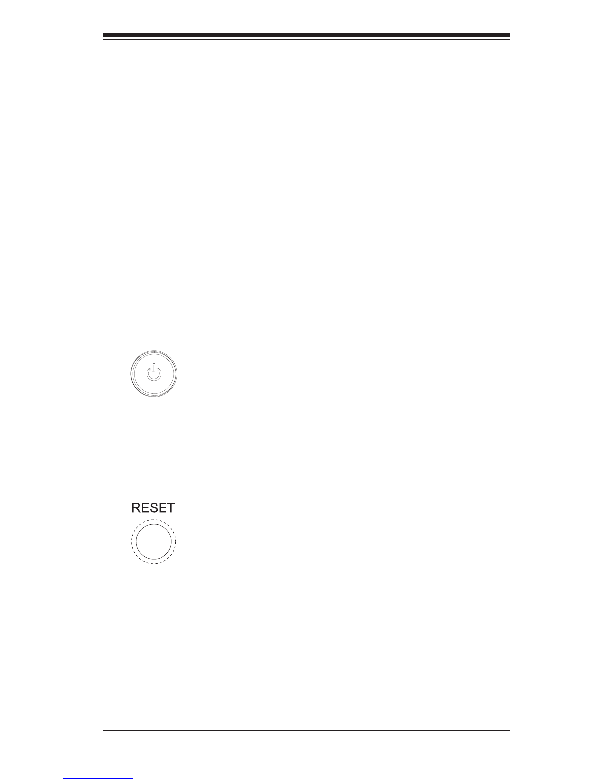
3-2 Control Panel Buttons
There are two push-buttons located on the front of the chassis: a power on/off
button and a reset button.
Power
This is the main power button, which is used to apply or turn off the main system
power. Turning off system power with this button removes the main power but keeps
standby power supplied to the system.
Reset
Use the reset button to reboot the system.
3-2
SuperWorkstation 5037A-I User's Manual
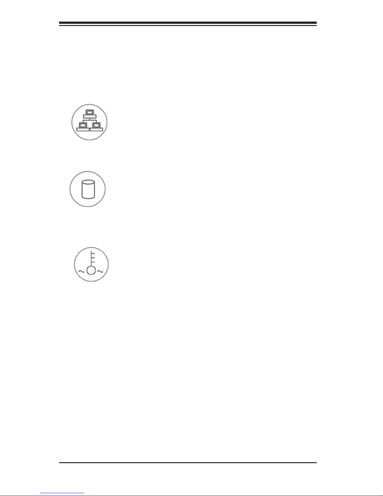
3-3 Control Panel LEDs
The control panel located on the front of the SC732D4-903B chassis has three LEDs
that provide you with critical information related to different parts of the system.
This section explains what each LED indicates when illuminated and any corrective
action you may need to take.
Overheat/Fan Fail
When Flashing: This LED indicates a fan failure.
When Continuously On (not ashing): This LED indicates an overheat condi-
tion caused by cables obstructing the airow in the system or the ambient room
temperature being too warm.
Correcting an Overheat/Fan Fail Condition
1. Check the routing of the cables and move any cables that restrict airow.
2. Conrm that all fans are operating normally.
3. Verify that the heatsinks are installed properly.
4. If the chassis cover is not aligned correctly, the airow may be disrupted. This
leads to overheating. Conrm that the chassis cover is placed correctly.
5. This LED will remain active as long as the overheat condition exists.
HDD: Indicates IDE channel activity in the SAS/SATA drive, and/or DVD-ROM drive
activity when ashing.
NIC: Indicates network activity on GLAN when ashing.
Chapter 4: System Safety
4-1
Chapter 4
System Safety
4-1 Electrical Safety Precautions
!
Basic electrical safety precautions should be followed to protect yourself from
harm and the SuperWorkstation 5037A-I from damage:
•Be aware of the locations of the power on/off switch on the chassis as well
as the room's emergency power-off switch, disconnection switch or electrical
outlet. If an electrical accident occurs, you can then quickly remove power from
the system.
•Do not work alone when working with high-voltage components.
•Power should always be disconnected from the system when removing or install-
ing main system components, such as the motherboard, memory modules and
the DVD-ROM. When disconnecting power, you should rst power down the sys-
tem with the operating system. The unit has more than one power supply cord.
Disconnect both power supply cords before servicing to avoid electrical shock.
•When working around exposed electrical circuits, another person who is familiar
with the power-off controls should be nearby to switch off the power if neces-
sary.
•Use only one hand when working with powered-on electrical equipment. This
is to avoid making a complete circuit, which will cause electrical shock. Use
extreme caution when using metal tools, which can easily damage any electrical
components or circuit boards they come into contact with.
•Do not use mats designed to decrease electrostatic discharge as protection from
electrical shock. Instead, use rubber mats that have been specically designed
as electrical insulators.
•The power supply power cord must include a grounding plug and must be
plugged into grounded electrical outlets.
SuperWorkstation 5037A-I User's Manual
4-2
4-2 General Safety Precautions
Follow these rules to ensure general safety:
•Keep the area around the SuperWorkstation 5037A-I clean and free of clutter.
•The 5037A-I weighs approximately 29.5 lbs (13.38 kg.) when fully loaded. When
lifting the system, two people at either end should lift slowly with their feet spread
out to distribute the weight. Always keep your back straight and lift with your
legs. Don't use the handles (if installed) to lift the chassis; the handles should
only be used to pull the server out of the rack.
•Place the chassis top cover and any system components that have been re-
moved away from the system or on a table so that they won't accidentally be
stepped on.
•While working on the system, do not wear loose clothing such as neckties and
unbuttoned shirt sleeves, which can come into contact with electrical circuits or
be pulled into a cooling fan.
•Remove any jewelry or metal objects from your body, which are excellent metal
conductors that can create short circuits and harm you if they come into contact
with printed circuit boards or areas where power is present.
!
•Motherboard battery: CAUTION - There is a danger of explosion if the onboard
battery is installed upside down, which will reverse its polarities (see Figure 4-1).
This battery must be replaced only with the same or an equivalent type recom-
mended by the manufacturer (CR2032). Dispose of used batteries according to
the manufacturer's instructions.
•DVD-ROM laser: CAUTION - this server may have come equipped with a
DVD-ROM drive. To prevent direct exposure to the laser beam and hazardous
radiation exposure, do not open the enclosure or use the unit in any uncon-
ventional way.
•Mainboard replaceable soldered-in fuses: Self-resetting PTC (Positive Tempera-
ture Coefcient) fuses on the mainboard must be replaced by trained service
technicians only. The new fuse must be the same or equivalent as the one
replaced. Contact technical support for details and support.
Chapter 4: System Safety
4-3
4-3 ESD Precautions
Electrostatic discharge (ESD) is generated by two objects with different electrical
charges coming into contact with each other. An electrical discharge is created to
neutralize this difference, which can damage electronic com ponents and printed
circuit boards. The following measures are generally sufcient to neutralize this
difference before contact is made to protect your equipment from ESD:
•Use a grounded wrist strap designed to prevent static discharge.
•Keep all components and printed circuit boards (PCBs) in their antistatic bags
until ready for use.
•Touch a grounded metal object before removing the board from the antistatic
bag.
•Do not let components or PCBs come into contact with your clothing, which may
retain a charge even if you are wearing a wrist strap.
•Handle a board by its edges only; do not touch its components, peripheral chips,
memory modules or contacts.
•When handling chips or modules, avoid touching their pins.
•Put the motherboard and peripherals back into their antistatic bags when not
in use.
•For grounding purposes, make sure your computer chassis provides excellent
conductivity between the power supply, the case, the mounting fasteners and
the motherboard.
!
•After accessing the inside of the system, close the system back up and secure
it to the rack unit with the retention screws after ensuring that all connections
have been made.

SuperWorkstation 5037A-I User's Manual
4-4
4-4 Operating Precautions
Care must be taken to assure that the chassis cover is in place when the system
is operating to assure proper cooling. Out of warranty damage to the system can
occur if this practice is not strictly followed.
!
Figure 4-1. Installing the Onboard Battery
!
Please handle used batteries carefully. Do not damage the battery in any way; a
damaged battery may release hazardous materials into the environment. Do not
discard a used battery in the garbage or a public landll. Please comply with the
regulations set up by your local hazardous waste management agency to dispose
of your used battery properly.
Chapter 5: Advanced Serverboard Setup
5-1
Chapter 5
Advanced Motherboard Setup
This chapter covers the steps required to install the X9SRA motherboard into the
chassis, connect the data and power cables and install add-on cards. All mother-
board jumpers and connections are also described. A layout and quick reference
chart are included in this chapter for your reference. Remember to completely close
the chassis when you have nished working with the motherboard to better cool
and protect the system.
5-1 Handling the Motherboard
Electrostatic discharge (ESD) can damage electronic com ponents. To prevent dam-
age to any printed circuit boards (PCBs), it is important to handle them very carefully
(see previous chapter). To prevent the motherboard from bending, keep one hand
under the center of the board to support it when handling. The following measures
are generally sufcient to protect your equipment from electric static discharge.
Cautions
•Use a grounded wrist strap designed to prevent electrostatic discharge.
•Touch a grounded metal object before removing any board from its antistatic
bag.
•Handle a board by its edges only; do not touch its components, peripheral chips,
memory modules or gold contacts.
•When handling chips or modules, avoid touching their pins.
•Put the motherboard, add-on cards and peripherals back into their antistatic
bags when not in use.
•For grounding purposes, make sure your computer chassis provides excellent
conductivity between the power supply, the case, the mounting fasteners and
the motherboard.

5-2
SuperWorkstation 5037A-I User's Manual
Unpacking
The motherboard is shipped in antistatic packaging to avoid electrical static dis-
charge. When unpacking the board, make sure the person handling it is static
protected.
5-2 Motherboard Installation
This section explains the rst step of physically mounting the X9SRA into the
SC732D4-903B chassis. Following the steps in the order given will eliminate the
most common problems encountered in such an installation. To remove the moth-
erboard, follow the procedure in reverse order.
Installing to the Chassis
1. Access the inside of the system by laying the chassis on a at surface, re-
moving the screws from the back lip of the top cover of the chassis, then pull
the cover off.
2. Make sure that the I/O ports on the motherboard align properly with their
respective holes in the I/O shield at the back of the chassis.
3. Carefully mount the motherboard to the motherboard tray by aligning the
board holes with the raised metal standoffs that are visible in the chassis.
4. Insert screws into all the mounting holes on your motherboard that line up
with the standoffs and tighten until snug (if you screw them in too tight, you
might strip the threads). Metal screws provide an electrical contact to the
motherboard ground to provide a continuous ground for the system.
5. Finish by reinstalling the top cover onto the chassis.
Caution: To avoid damaging the motherboard and its components, do not apply
any force greater than 8 lbs. per square inch when installing a screw into a mount-
ing hole.

Chapter 5: Advanced Serverboard Setup
5-3
5-3 Connecting Cables
Now that the motherboard is installed, the next step is to connect the cables to the
board. These include the data (ribbon) cables for the peripherals and control panel
and the power cables.
Connecting Data Cables
The cables used to transfer data from the peripheral devices have been carefully
routed to prevent them from blocking the ow of cooling air that moves through the
system from front to back. If you need to disconnect any of these cables, you should
keep them routed as they were originally after reconnecting them (make sure the red
wires connect to the pin 1 locations). The following data cables (with their locations
noted) should be connected. (See the layout on page 5-9 for connector locations.)
•SATA drive data cables (I-SATA0 ~ I-SATA5)
•Control panel cable (JF1)
•SGPIO cable (T-SGPIO1, T-SGPIO2)
Caution: Make sure that the cables do not come into contact with the fans.
Connecting Power Cables
The X9SRA has a 24-pin primary power supply connector (JPW1) for connection to
the ATX power supply. In addition, the 8-pin secondary power connector (JPWR2)
must also be connected to your power supply. See Section 5-9 for power connec-
tor pin denitions.
Connecting the Control Panel
JF1 contains header pins for various front control panel connectors. See Figure 5-1
for the pin locations of the various front control panel buttons and LED indicators.
All JF1 wires have been bundled into a single ribbon cable to simplify this connec-
tion. Make sure the red wire plugs into pin 1 as marked on the board. The other
end connects to the Control Panel PCB board, located just behind the system status
LEDs on the chassis. See Chapter 5 for details and pin descriptions.
5-4
SuperWorkstation 5037A-I User's Manual
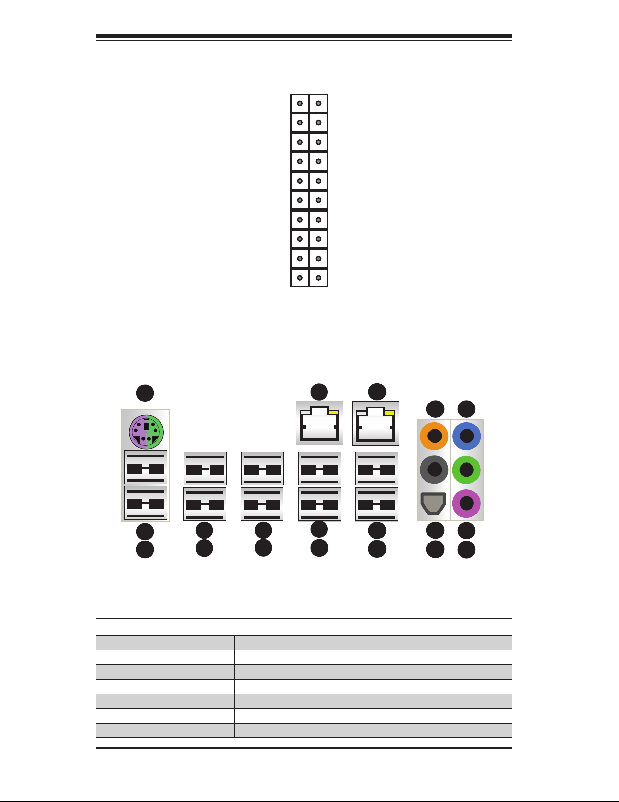
5-4 I/O Ports
The I/O ports are color coded in conformance with the PC 99 specication. See
Figure 5-2 below for the colors and locations of the various I/O ports.
Figure 5-1. Control Panel Header Pins
NMI
X
LED VCC
LED VCC
LED VCC
LED VCC
LED VCC
LED VCC
#3 - 4 Reset Button
#1 - 2 Power Button
Ground
X .
Power On LED
HDD LED
NIC1 LED
NIC2 LED
OH/Fan Fail LED
Power Fail LED
Ground
Ground
2 1
20 19
1
1
1
10
1
11
1
12
1
13
1
14
1
15
1
18
1
16
1
19
1
17
1
2
1
3
1
4
1
5
1
6
1
7
1
8
1
9
Motherboard I/O Backpanel
1. Keyboard/Mouse 7. USB 2.0 Port 5 13. USB 2.0 Port 7
2. USB 2.0 Port 0 8. LAN 1 Port 14. Center/LFE Out
3. USB 2.0 Port 1 9. USB 3.0 Port 0 15. Surround Out
4. USB 2.0 Port 2 10. USB 3.0 Port 1 16. S/P DIF Out
5. USB 2.0 Port 3 11. LAN 2 Port 17. Line In
6. USB 2.0 Port 4 12. USB 2.0 Port 6 18. Line Out
19. Mic In
Chapter 5: Advanced Serverboard Setup
5-5
5-5 Processor and Heatsink Installation
Caution: When handling the processor package, avoid placing direct pressure on
the label area of the fan.
Notes:
•Always connect the power cord last and always remove it before adding, re-
moving or changing any hardware components. Make sure that you install the
processor into the CPU socket before you install the CPU heatsink.
•If you buy a CPU separately, make sure that you use an Intel-certied multi-
directional heatsink only.
•Make sure to install the motherboard into the chassis before you install the
CPU heatsinks.
•When receiving a motherboard without a processor pre-installed, make sure that
the plastic CPU socket cap is in place and none of the socket pins are bent;
otherwise, contact your retailer immediately.
•Refer to the Supermicro Web site for updates on CPU support.
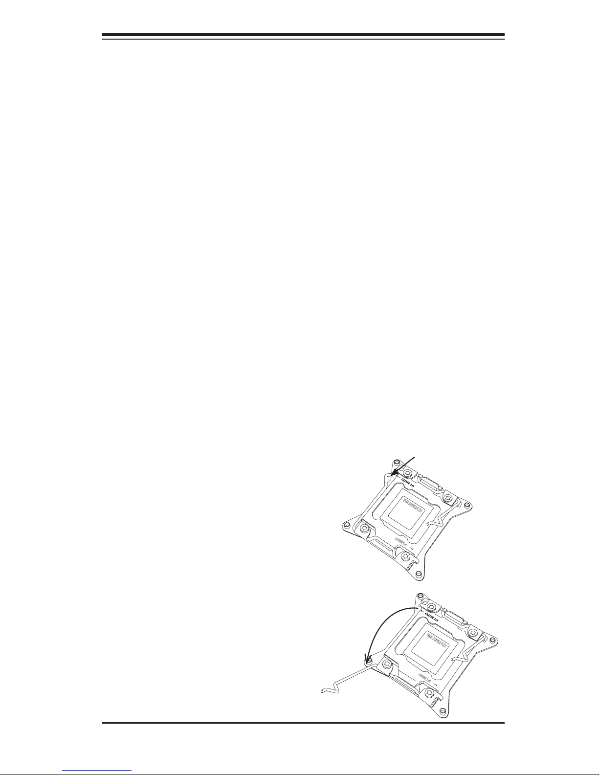
Installing an LGA 2011 Processor
1. There are two levers on the
LGA2011 socket. First press and
release the load lever labeled
'Open 1st'.
2. Press the second load lever
labeled 'Close 1st' to release the
load plate from its locked position.
OPEN 1st
WARNING!
OPEN 1st
WARNING!
Press down on
the lever labeled
'Close 1st'
Pull lever away
from the socket
5-6
SuperWorkstation 5037A-I User's Manual
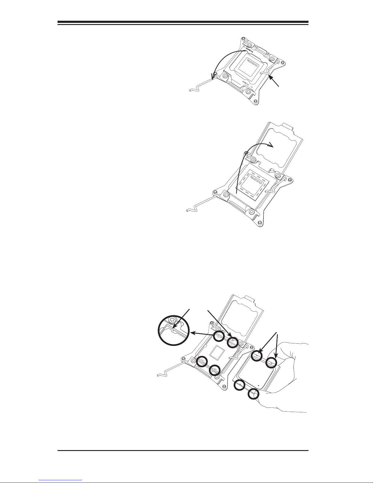
3. With the lever labeled 'Close 1st'
fully retracted, gently push down
on the 'Open 1st' lever to open the
load plate. Lift the load plate to
open it completely.
4. Using your thumb and the index
nger, remove the 'WARNING'
plastic cap from the socket.
WARNING!
OPEN 1st
WARNING!
Socket Keys
CPU Keys
Gently push
down to pop
the load plate
open.
5. Use your thumb and index nger
to hold the CPU by its edges. Align
the CPU keys, which are semi-
circle cutouts, against the socket
keys.
6. Once they are aligned,
carefully lower the CPU
straight down into the
socket. (Do not drop
the CPU on the socket.
Do not move the CPU
horizontally or verti-
cally and do not rub the
CPU against any pins of
the socket, which may
damage the CPU or the
socket.)
Chapter 5: Advanced Serverboard Setup
5-7
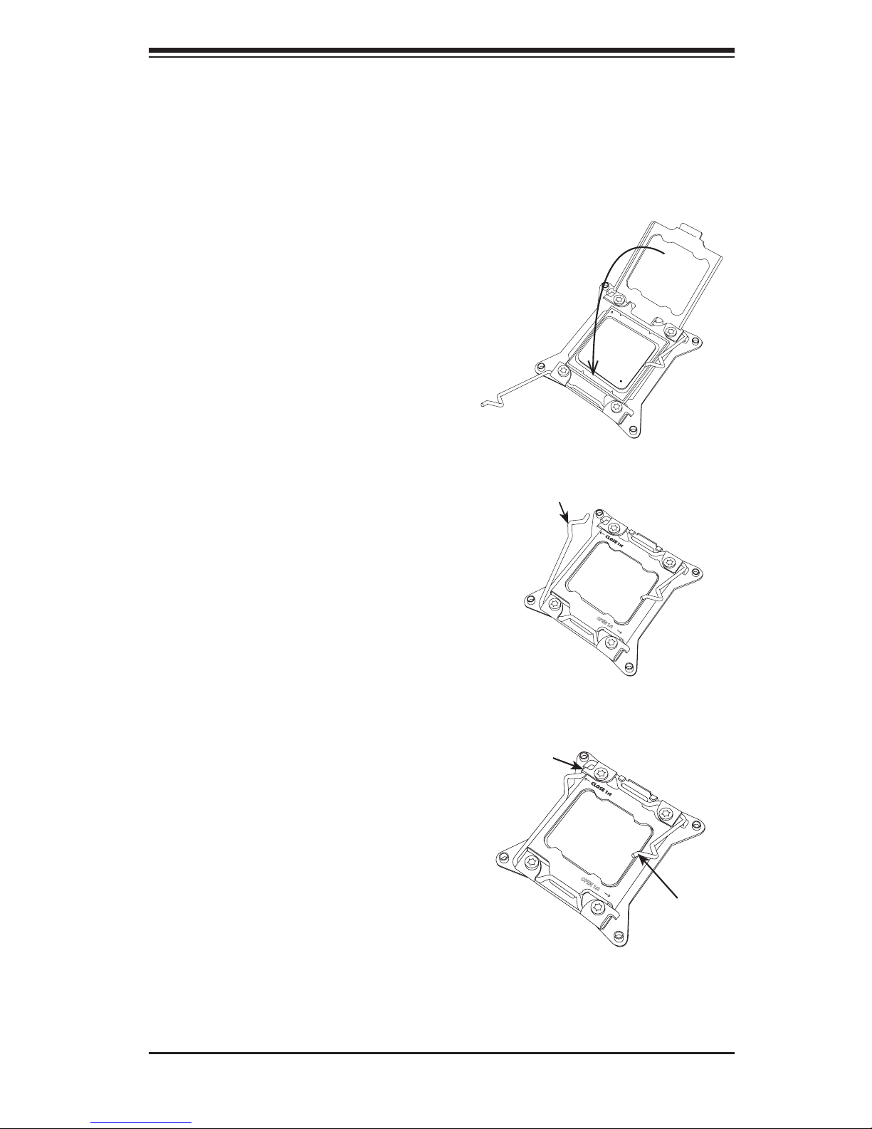
Caution: You can only install the CPU to the socket in one direction. Make sure
that the CPU is properly inserted into the socket before closing the load plate. If it
doesn't close properly, do not force it as it may damage your CPU. Instead, open
the load plate again and double-check that the CPU is aligned properly.
OPEN 1st
OPEN 1st
Lever Lock
Push down
and lock the
lever labeled
'Open 1st'.
Push down and lock the
level labeled 'Close 1st'.
Gently close
the load plate.
7. With the CPU in the socket, in-
spect the four corners of the CPU
to make sure that they are ush
with the socket.
8. Close the load plate. Lock the
lever labeled 'Close 1st', then lock
the lever labeled 'Open 1st'. Use
your thumb to gently push the load
levers down until the lever locks.
5-8
SuperWorkstation 5037A-I User's Manual
Screw#1
Screw#2
Installing a CPU Heatsink
Caution: Remove the power cord before installing heatsinks. Do not reconnect it
until the installation is completed. See http://www.supermicro.com/about/policies/
safety_information.cfm.
1. Do not apply any thermal grease to the heatsink or the CPU die; the required
amount has already been applied.
2. Place the heatsink on top of the CPU so that the four mounting holes are
aligned with those on the motherboard and the heatsink bracket underneath.
3. Screw in two diagonal screws (i.e., the #1 and the #2 screws) until just snug.
(To avoid possible damage to the CPU do not over-tighten the screws.)
4. Finish the installation by fully tightening all four screws.
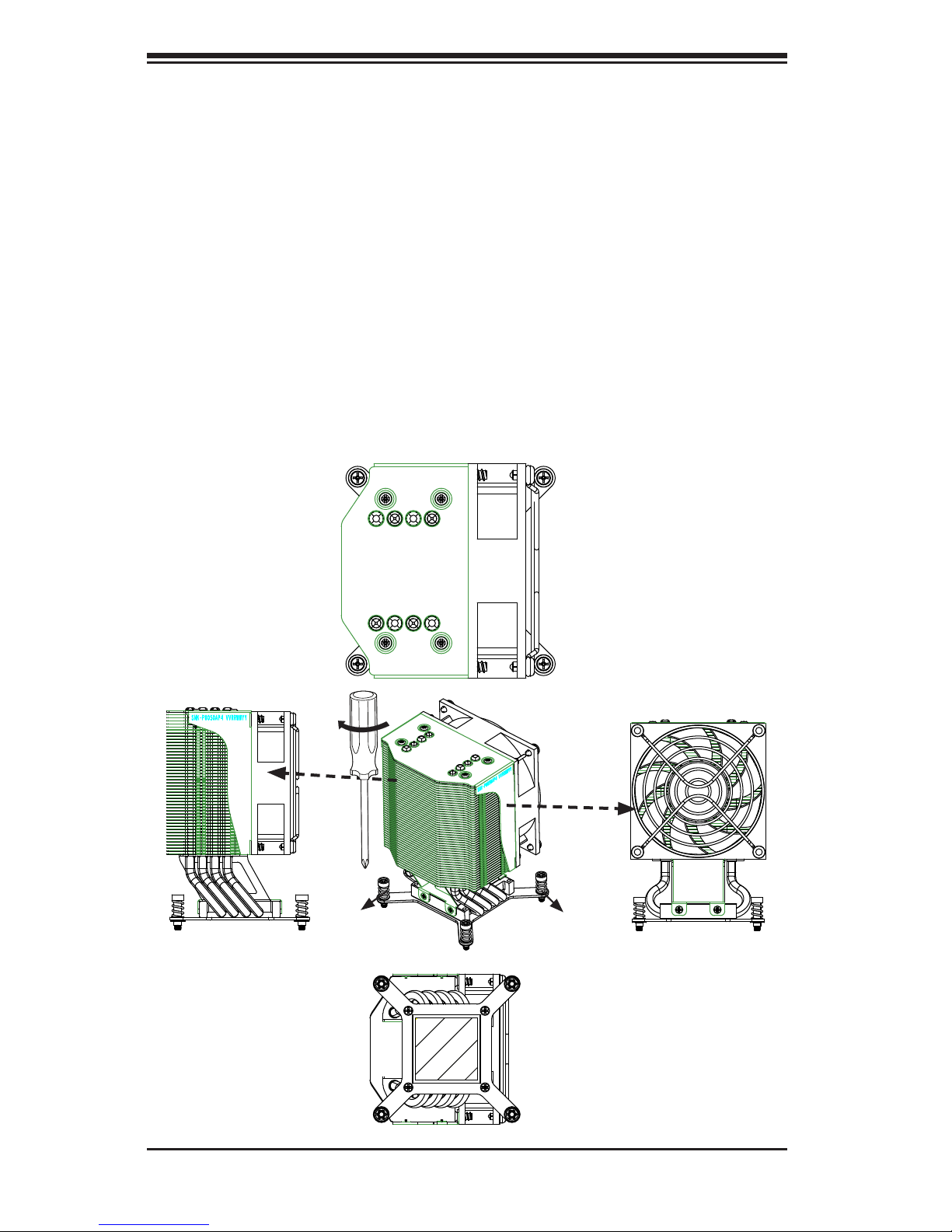
Screw#3
Top View
Bottom View
Side View
Side View
Screw#1
Screw#2Screw#3
Screw#4
 Loading...