

Supero SUPERSERVER AS-4021GA-62R+F User Manual
SUPER
SUPERSERVER
AS-4021GA-62R+F
®
USER’S MANUAL
Revision 1.0a

The information in this User’s Manual has been carefully reviewed and is believed to be accurate.
The vendor assumes no responsibility for any inaccuracies that may be contained in this document,
makes no commitment to update or to keep current the information in this manual, or to notify any
person or organization of the updates. Please Note: For the most up-to-date version of this
manual, please see our web site at www.supermicro.com.
Super Micro Computer, Inc. ("Supermicro") reserves the right to make changes to the product
described in this manual at any time and without notice. This product, including software, if any,
and documentation may not, in whole or in part, be copied, photocopied, reproduced, translated or
reduced to any medium or machine without prior written consent.
IN NO EVENT WILL SUPERMICRO BE LIABLE FOR DIRECT, INDIRECT, SPECIAL, INCIDENTAL,
SPECULATIVE OR CONSEQUENTIAL DAMAGES ARISING FROM THE USE OR INABILITY TO
USE THIS PRODUCT OR DOCUMENTATION, EVEN IF ADVISED OF THE POSSIBILITY OF
SUCH DAMAGES. IN PARTICULAR, SUPERMICRO SHALL NOT HAVE LIABILITY FOR ANY
HARDWARE, SOFTW ARE, OR DA TA STORED OR USED WITH THE PRODUCT, INCLUDING THE
COSTS OF REPAIRING, REPLACING, INTEGRATING, INSTALLING OR RECOVERING SUCH
HARDWARE, SOFTWARE, OR DATA.
Any disputes arising between manufacturer and customer shall be governed by the laws of Santa
Clara County in the State of California, USA. The State of California, County of Santa Clara shall
be the exclusive venue for the resolution of any such disputes. Super Micro's total liability for all
claims will not exceed the price paid for the hardware product.
FCC Statement: This equipment has been tested and found to comply with the limits for a Class A
digital device pursuant to Part 15 of the FCC Rules. These limits are designed to provide reasonable
protection against harmful interference when the equipment is operated in a commercial environment. This equipment generates, uses, and can radiate radio frequency energy and, if not installed
and used in accordance with the manufacturer’s instruction manual, may cause harmful interference
with radio communications. Operation of this equipment in a residential area is likely to cause harmful
interference, in which case you will be required to correct the interference at your own expense.
California Best Management Practices Regulations for Perchlorate Materials: This Perchlorate warning applies only to products containing CR (Manganese Dioxide) Lithium coin cells. “Perchlorate
Material-special handling may apply. See www.dtsc.ca.gov/hazardouswaste/perchlorate”
WARNING: Handling of lead solder materials used in this
product may expose you to lead, a chemical known to the
State of California to cause birth defects and other reproductive harm.
Manual Revision 1.0a
Release Date: January 29, 2010
Unless you request and receive written permission from Super Micro Computer, Inc., you may not
copy any part of this document.
Information in this document is subject to change without notice. Other products and companies
referred to herein are trademarks or registered trademarks of their respective companies or mark
holders.
Copyright © 2010 by Super Micro Computer, Inc.
All rights reserved.
Printed in the United States of America
Preface
About This Manual
This manual is written for professional system integrators and PC technicians. It
provides information for the installation and use of the SuperServer AS-4021GA62R+F. Installation and maintenance should be performed by experienced technicians only.
The SuperServer AS-4021GA-62R+F is based on the SC747TG-R1400SQ 4U/
Tower rackmount server chassis and the Super H8DA6+-F serverboard. Please
refer to our web site for an up-to-date list of supported operating systems, processors and memory.
Manual Organization
Preface
Chapter 1: Introduction
The fi rst chapter provides a checklist of the main components included with the
server system and describes the main features of the Super H8DA6+-F serverboard
and the SC747TG-R1400SQ chassis.
Chapter 2: Server Installation
This chapter describes the steps necessary to install the system into a rack and
check out the server confi guration prior to powering up the system. If your server
was ordered without the processor and memory components, this chapter will refer
you to the appropriate sections of the manual for their installation.
Chapter 3: System Interface
Refer to this chapter for details on the system interface, which includes the functions
and information provided by the control panel on the chassis as well as other LEDs
located throughout the system.
Chapter 4: System Safety
You should thoroughly familiarize yourself with this chapter for a general overview
of safety precautions that should be followed when installing and servicing the
system.
Chapter 5: Advanced Serverboard Setup
Chapter 5 provides detailed information on the H8DA6+-F serverboard, including the
locations and functions of connectors, headers and jumpers. Refer to this chapter
iii

SUPERSERVER AS-4021GA-62R+F User's Manual
when adding or removing processors or main memory and when reconfi guring the
serverboard.
Chapter 6: Advanced Chassis Setup
Refer to Chapter 6 for detailed information on the SC747TG-R1400SQ 4U/Tower
rackmount server chassis. You should follow the procedures given in this chapter
when installing, removing or reconfi guring Serial ATA or peripheral drives and when
replacing system power supply units and cooling fans.
Chapter 7: BIOS
The BIOS chapter includes an introduction to BIOS and provides detailed information on running the CMOS Setup Utility.
Appendix A: BIOS POST Messages
Appendix B: BIOS POST Codes
Appendix C: System Specifi cations
iv

Notes
Preface
v

SUPERSERVER AS-4021GA-62R+F User's Manual
Table of Contents
Chapter 1 Introduction
1-1 Overview .........................................................................................................1-1
1-2 Serverboard Features .....................................................................................1-2
Processors ......................................................................................................1-2
HyperTransport Technology ............................................................................ 1-2
Memory ...........................................................................................................1-2
Serial ATA ....................................................................................................... 1-2
SAS .................................................................................................................1-3
PCI Expansion Slots ....................................................................................... 1-3
Onboard Controllers/Ports .............................................................................. 1-3
IPMI .................................................................................................................1-3
Other Features ................................................................................................1-3
1-3 Server Chassis Features ................................................................................ 1-3
System Power .................................................................................................1-4
Mounting Rails (optional) ................................................................................ 1-4
Hard Drive/Drive Bays ....................................................................................1-4
Front Control Panel ......................................................................................... 1-4
Cooling System ...............................................................................................1-4
Backplane ........................................................................................................ 1-4
1-5 Contacting Supermicro ....................................................................................1-6
Chapter 2 System Setup
2-1 Overview .........................................................................................................2-1
2-2 Unpacking the System ....................................................................................2-1
2-3 Setting Up the System ....................................................................................2-2
Checking the Motherboard Setup ...................................................................2-2
Checking the Drive Bay Setup ........................................................................2-2
Rack Precautions ............................................................................................2-4
Rack Mounting Considerations .......................................................................2-5
Removing the Chassis Cover and Feet .......................................................... 2-6
Installing the Chassis Handles and Inner Rails ..............................................2-8
Installing the Outer Rails to the Rack ............................................................. 2-9
Installing the Chassis into a Rack.................................................................2-10
Installing the Chassis Cover ..........................................................................2-11
Installing Feet on the Chassis ...................................................................... 2-12
Chapter 3 System Interface
3-1 Overview .........................................................................................................3-1
3-2 Control Panel Buttons ..................................................................................... 3-2
vi

Table of Contents
3-3 Control Panel LEDs ........................................................................................3-2
3-4 Drive Carrier LEDs .......................................................................................... 3-4
SAS/SATA Drives ............................................................................................ 3-4
Chapter 4 System Safety
4-1 Electrical Safety Precautions .......................................................................... 4-1
4-2 General Safety Precautions ............................................................................ 4-2
4-3 ESD Precautions ............................................................................................. 4-3
4-4 Operating Precautions .................................................................................... 4-4
Chapter 5 Advanced Serverboard Setup
5-1 Handling the Serverboard ............................................................................... 5-1
Precautions .....................................................................................................5-1
Unpacking .......................................................................................................5-2
5-2 Serverboard Installation ..................................................................................5-2
I/O Slot Shield Installation ...............................................................................5-2
Permanent and Optional Standoffs .................................................................5-3
Installing the Motherboard ..............................................................................5-4
5-3 Connecting Cables .......................................................................................... 5-5
Connecting Data Cables ................................................................................. 5-5
Connecting Power Cables .............................................................................. 5-5
Connecting the Control Panel ......................................................................... 5-5
5-4 I/O Ports ..........................................................................................................5-6
5-5 Installing the Processor and Heatsink ............................................................ 5-7
Installing a CPU Processor ............................................................................. 5-7
Installing a CPU Heatsink ............................................................................... 5-9
Removing the Heatsink ................................................................................. 5-10
5-6 Installing Memory ...........................................................................................5-11
Memory Support .............................................................................................5-11
Memory Support ....................................................................................... 5-12
5-6 Adding PCI Add-On Cards ............................................................................5-13
Installing Double-Width Graphics Cards ....................................................... 5-15
5-7 Serverboard Details ...................................................................................... 5-17
5-8 Connector Defi nitions ................................................................................... 5-19
5-9 Jumper Settings ............................................................................................5-26
Explanation of Jumpers ................................................................................ 5-26
5-10 Onboard Indicators ........................................................................................5-29
5-11 Floppy, IDE, SAS and SATA Drive Connections ...........................................5-30
5-12 Enabling SATA RAID .....................................................................................5-32
Serial ATA (SATA)..........................................................................................5-32
Installing the OS/SATA Driver ....................................................................... 5-32
vii

SUPERSERVER AS-4021GA-62R+F User's Manual
Building a Driver Diskette .........................................................................5-32
Enabling SATA RAID in the BIOS ............................................................ 5-33
Using the Adaptec RAID Utility ..................................................................... 5-34
Installing the RAID Driver During OS Installation ......................................... 5-34
5-13 Installing Drivers ............................................................................................5-35
Supero Doctor III ........................................................................................... 5-36
Chapter 6 Advanced Chassis Setup
6-1 Static-Sensitive Devices ..................................................................................6-2
Precautions .....................................................................................................6-2
6-2 Control Panel ..................................................................................................6-2
6-3 System Cooling ............................................................................................... 6-3
System Fan Failure ......................................................................................... 6-3
Replacing System Fans .................................................................................. 6-3
6-4 Power Supply .................................................................................................. 6-5
Power Supply Failure ...................................................................................... 6-5
Replacing the Power Supply ...........................................................................6-5
Power Supply Connections ............................................................................. 6-6
6-5 Confi guring the the Storage Module ..............................................................6-7
Tower or Rack Confi guration...........................................................................6-7
Rotating the Storage Module .......................................................................... 6-8
Installing Drives in the Storage Module .......................................................... 6-9
Removing a Drive Carrier ............................................................................. 6-10
Adding Peripheral Drives .............................................................................. 6-12
Adding Five Hard Drives Using a Supermicro Mobile Rack .........................6-13
6-6 Installing Hard Drives in the Chassis ............................................................6-14
Chapter 7 BIOS
7-1 Introduction ......................................................................................................7-1
Starting BIOS Setup Utility ..............................................................................7-1
How To Change the Confi guration Data ......................................................... 7-1
Starting the Setup Utility ................................................................................. 7-2
7-2 Main Setup ...................................................................................................... 7-2
7-3 Advanced Settings Menu ................................................................................ 7-3
7-4 Security Menu ...............................................................................................7-16
7-5 Boot Menu ..................................................................................................... 7-16
7-6 Exit Menu ...................................................................................................... 7-17
Appendix A BIOS Error Beep Codes
A-1 BIOS Error Beep Codes ................................................................................. A-1
viii

Table of Contents
Appendix B Installing Windows
B-1 Installing Windows for a RAID System ........................................................... B-1
B-2 Installing Windows for a Non-RAID System ................................................... B-2
Appendix C System Specifi cations

SUPERSERVER AS-4021GA-62R+F User's Manual
Notes
Chapter 1: Introduction
Chapter 1
Introduction
1-1 Overview
The SuperServer AS-4021GA-62R+F is a supercomputing server that is comprised
of two main subsystems: the SC747TG-R1400SQ 4U/Tower server chassis and the
H8DA6+-F dual AMD Socket F type processor serverboard. Please refer to our web
site for information on operating systems that have been certifi ed for use with the
system (www.supermicro.com).
In addition to the serverboard and chassis, various hardware components have
been included with the server, as listed below:
Two (2) 4-wire Active Heatsinks for Socket F processors (SNK-P0024AP4)
•
Two (2) 92x38-mm 4-pin PWM cooling fans with housing (FAN-0082L4)•
Two (2) 92x38-mm 4-pin PWM cooling fan with housing (FAN-0114L4)•
SAS accessories:•
One (1) IEEE 1394 (Firewire) Cable (CBL-0173L)
One (1) I/O shield (MCP-260-00025-0N)
One (1) HD backplane (BPN-SAS-747TQ)
Two (2) 23-cm IPASS to 4 SATA cables (CBL-0118L)
Eight (8) 3.5" hard disk drive trays (MCP-220-97301-0B)
One (1) 5.25" drive tray (MCP-220-00073-0B)
Chassis cables:
•
One (1) 30-inch Round 16 to 16-pin ribbon front panel cable (CBL-0071L)
Four (4) 20-cm 4 to 4-pin middle fan power extension cables (CBL-0216L)
Two (2) 30-cm 4 to 4-pin rear fan power extension cables (CBL-0286L)
One (1) 4U 17.2" width rail set (MCP-290-00059-0N) (optional)
•
One (1) Supermicro CD containing drivers and utilities•
1-1

SUPERSERVER AS-4021GA-62R+F User's Manual
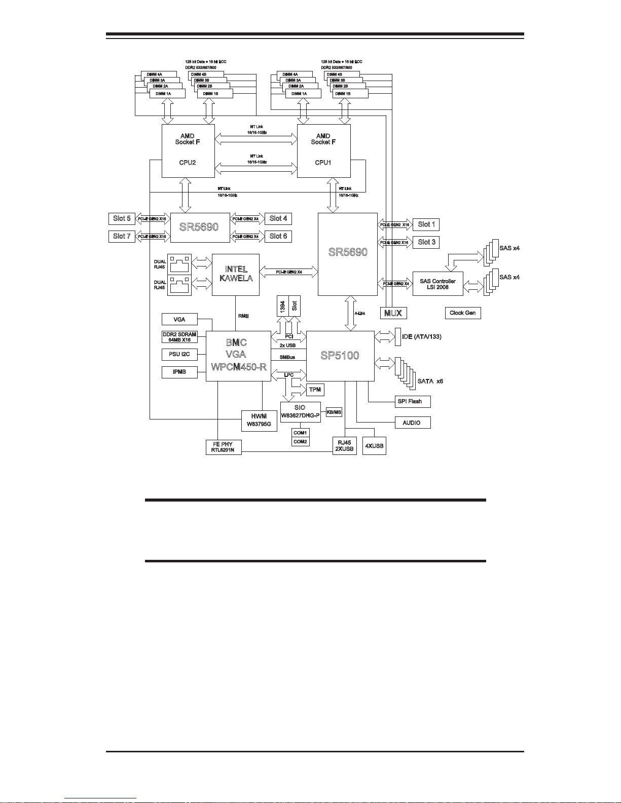
1-2 Serverboard Features
At the heart of the SuperServer AS-4021GA-62R+F lies the H8DA6+-F, a dual
processor serverboard based on the AMD SR5690 and AMD SP5100 chipsets.
Below are the main features of the H8DA6+-F. (See Figure 1-1 for a block diagram
of the chipset).
Processors
The H8DA6+-F supports two AMD Opteron 2000 series (Socket F type) processors.
and the the AMD SR5690/SP5100 chipset, which functions as a Media and Communications Processor (MCP). Controllers for the system memory are integrated
directly into AMD Opteron processors Please refer to the serverboard description
pages on our web site for a complete listing of supported processors (www.supermicro.com).
HyperTransport Technology
HyperTransport technology is a high-speed, low latency point to point link that was
designed to increase the communication speed by a factor of up to 48x between
integrated circuits. This is done partly by reducing the number of buses in the
chipset to reduce bottlenecks and by enabling a more effi cient use of memory
in multi-processor systems. The end result is a signifi cant increase in bandwidth
within the chipset.
Memory
The H8DA6+-F has Sixteen single/dual channel DIMM slots supporting up to 128
GB of DDR2-800/667/533 registered ECC SDRAM. Modules of the same size and
speed are recommended (for Unbuffered ECC/Non-ECC memory, a maximum of 2
GB per DIMM is supported). See Chapter 5 for details.
Serial ATA
A SATA controller is integrated into the SP5100 chipset to provide a six-port 3/
Gbs SATA subsystem, which is RAID 0, 1 and 10 supported. The SATA drives are
hot-swappable units.
Note: The operati ng system yo u use must h ave R AID su ppor t to e nable t he hotswap capability and RAI D function of the Serial ATA drives.
1-2
Chapter 1: Introduction
SAS
An LSI2008 SAS2 controller is integrated into the chipset to provide two IPASS
connectors that can serve up to 8 hot-swappable drive units. The SAS2 controller
can support RAID 0, 1, 10 and JBOD. An optional AOC-IMRRAKEY-2008-LSI key
provides RAID-5 support.
PCI Expansion Slots
The H8DA6+-F has four PCI-E Gen. 2.0 x16 slots (Slot 1, Slot 3, Slot 5, Slot 7),
two (2) PCI-Express x4 (in x8) Gen 2 slots (Slot 4, Slot 6) and one (1) PCI slot
(Slot 2).
Onboard Controllers/Ports
The color-coded I/O ports include one COM port (an additional COM header is
located on the serverboard), a VGA (monitor) port, ten USB 2.0 ports (six rear
USB ports, two front headers, and two Type A connections), PS/2 mouse and
keyboard ports, IPMI de dic a ted LAN p ort, Hi gh D efi nition A udi o p orts and two Gb
Ethernet ports.
IPMI
IPMI (Intelligent Platform Management Interface) is a hardware-level interface specifi cation that provides remote access, monitoring and administration for Supermicro
server platforms. IPMI allows server administrators to view a server’s hardware
status remotely, receive an alarm automatically if a failure occurs, and power cycle
a system that is non-responsive.
Other Features
Other onboard features that promote system health include onboard voltage
monitors, auto-switching voltage regulators, a chassis intrusion header, keyboar d
wakeup from s o ft- off, con s ol e r e di r e c t i o n, chassis and CPU overheat sensors, fan
status monitor with fi rmware control, Pulse Width M odu lati on (PW M) Fan Co ntrol,
power-up mode control for recovery from AC power loss, main switch override
mecha nism, ACPI Powe r Mana gement , system re sourc e ale rt v ia Supe ro Doc tor
III, virus protection and BIOS rescue.
1-3 Server Chassis Features
The following is a general outline of the main features of the SC747TG-R1400SQ
server chassis.
1-3

SUPERSERVER AS-4021GA-62R+F User's Manual
System Power
Each SC747 chassis model includes a Gold level 1400W High-effi ciency redundant
(1+1) power supply (93%), rated at 1400 Watts. In the unlikely event your power
supply fails, replacement is simple and can be done without tools. The AC power
cord should be removed from the system before servicing or replacing the power
supply. See Chapter 6 for details.
Mounting Rails (optional)
The SC747 can be placed in a rack for secure storage and use. To setup your rack,
follow the step-by-step instructions included in this manual in chapter 2.
Hard Drive/Drive Bays
The SC747 Chassis features eight slots for SAS/SATA drives. These drives are
hot -swappable. Once set up correctly , these drives can be removed without powering down the server.
Each SC747 Chassis provides three 5.25” peripheral drive bays for fl oppy drives,
DVD-ROM/CD-ROM Drives, or additional hard drives
Front Control Panel
The control panel on the server provides you with system monitoring and control.
LEDs indicate system power, HDD activity, network activity, system overheat, UID
and power supply failure. A main power button and a system reset button are also
included.
Cooling System
The SC747 chassis accepts four system fans and two rear exhaust fans. System
fans are powered from the serverboard. These fans are 4U high and are powered
by 4-pin connectors.
Backplane
Each SC747 chassis comes with a 4U backplane. Depending on your order, your
backplane will accept SAS/SATA. For more information regarding compatible backplanes, view the appendices found at the end of this manual. In addition, visit our
Web site for the latest information: http://www.supermicro.com.
1-4
Chapter 1: Introduction
Slot 5
Slot 7
DIMM 4A
DIMM 3A
DIMM 2A
DIMM 1A
PCI-E GEN2 X16
PCI-E GEN2 X16
DUAL
RJ45
DUAL
RJ45
128 bit Data + 16 bit ECC
DDR2 533/667/800
DIMM 4B
DIMM 3B
DIMM 2B
DIMM 1B
PCI-E GEN2 X4
PCI-E GEN2 X4
INTEL
RMII
BMC
VGA
HT Link
16/16-1GHz
HT Link
16/16-1GHz
HWM
W83795G
Slot 4
Slot 6
PCI-E GEN2 X4
2x USB
SMBus
W83627DHG-P
DDR2
AMD
Socket F
CPU2
HT 1 HT 1
HT Link
16/16-1GHz
SR5690
KAWELA
VGA
DDR2 SDRAM
64MB X16
PSU I2C
IPMB
WPCM450-R
FE PHY
RTL8201N
DIMM 4A
DIMM 3A
DIMM 2A
1394
PCI
LPC
DIMM 1A
Slot
SIO
COM1
COM2
H
T
0
Socket F
TPM
128 bit Data + 16 bit ECC
DDR2 533/667/800
DIMM 4B
DIMM 3B
DIMM 2B
DIMM 1B
DDR2
AMD
CPU1
HT Link
16/16-1GHz
SR5690
SP5100
KB/MS
RJ45
2XUSB
A-Link
4XUSB
PCI-E GEN2 X16
PCI-E GEN2 X16
PCI-E GEN2 X4
MUX
SPI Flash
Slot 1
Slot 3
SAS Controller
LSI 2008
IDE (ATA/133)
SA
TA x6
AUDIO
SAS x4
SAS x4
Clock Gen
Figure 1-1. AMD SR5690/SP5100 Chipset:
System Block Diagram
Note: This is a general block diagram and may not exactly represent
the features on your motherboard. See the previous pages for the
actual specifi cations of your motherboard.
1-5

SUPERSERVER AS-4021GA-62R+F User's Manual
1-5 Contacting Supermicro
Headquarters
Address: Super Micro Computer, Inc.
980 Rock Ave.
San Jose, CA 95131 U.S.A.
Tel: +1 (408) 503-8000
Fax: +1 (408) 503-8008
Email: marketing@supermicro.com (General Information)
support@supermicro.com (Technical Support)
Web Site: www.supermicro.com
Europe
Address: Super Micro Computer B.V.
Het Sterrenbeeld 28, 5215 ML
's-Hertogenbosch, The Netherlands
Tel: +31 (0) 73-6400390
Fax: +31 (0) 73-6416525
Email: sales@supermicro.nl (General Information)
support@supermicro.nl (Technical Support)
rma@supermicro.nl (Customer Support)
Asia-Pacifi c
Address: Super Micro, Taiwan
4F, No. 232-1, Liancheng Rd.
Chung-Ho 235, Taipei County
Taiwan, R.O.C.
Tel: +886-(2) 8226-3990
Fax: +886-(2) 8226-3991
Web Site: www.supermicro.com.tw
Technical Support:
Email: support@supermicro.com.tw
Tel: 886-2-8228-1366, ext.132 or 139
1-6
Chapter 2: Server Installation
Chapter 2
System Setup
2-1 Overview
This chapter provides a quick setup checklist to get your SuperServer AS-4021GA62R+F up and running. Following the steps in the order given should enable you
to have the system operational within a minimal amount of time. If your system is
not already fully integrated with a motherboard, processor, system memory etc.,
please turn to the chapter or section noted in each step for details on installing
specifi c components.
2-2 Unpacking the System
Y ou should inspect the box the SuperServer AS-4021GA-62R+F was shipped in and
note if it was damaged in any way. If the server itself shows damage, you should
fi le a damage claim with the carrier who delivered it.
Decide on a suitable location for setting up and operating the SuperServer AS4021GA-62R+F . It should be situated in a clean, dust-free area that is well ventilated.
Avoid areas where heat, electrical noise and electromagnetic fi elds are generated.
You will also need it placed near a grounded power outlet.
!
Review the electrical and general safety precautions in Chapter 4.•
Use a regulating uninterruptible power supply (UPS) to protect the server from •
power surges, voltage spikes and to keep your system operating in case of a
power failure.
Warnings and Precautions!
!
Allow the power supply units and Serial ATA drives to cool before touching
•
them.
To maintain proper cooling, always keep all chassis panels closed when not
•
being serviced.
2-1
SUPERSERVER AS-4021GA-62R+F User's Manual
2-3 Setting Up the System
You should fi rst open the left side panel (when facing the front of the chassis) to
make sure the motherboard is properly installed and all connections have been
made.
Warning: Only qualifi ed service technicians should access the inside of
the system. Except for short periods of time, do NOT operate the system
!
Checking the Motherboard Setup
Accessing the inside of the system: Begin by disconnecting the chassis from 1.
any power source. (A) Lift up and back on the main cover handle, which
secures the cover to the chassis. (B) Lift the main cover off of the chassis.
See Chapter 5 for details on Chassis covers and how to remove them.
without the cover in place. The chassis cover must be in place to allow
proper airfl ow and prevent overheating.
Check the CPU (processor): You may have a processor already installed into 2.
the system board. The processor should have its own heatsink attached. See
Chapter 5 for instructions on processor installation.
Check the system memory:3. Your system may have come with system
memory already installed. Make sure all DIMMs are fully seated in their slots.
For details on adding system memory, refer to Chapter 5.
Installing add-on cards:4. If desired, you can install up to seven add-on cards to
the system. See Chapter 5 for details on installing PCI- add-on cards.
Check all cable connections and airfl ow: Make sure all power and data cables 5.
are properly connected and not blocking the airfl ow. See Chapter 5 for details
on cable connections.
Checking the Drive Bay Setup
Next, you should check to make sure the peripheral drives and the SA T A drives have
been properly installed and all essential connections have been made.
Accessing the peripheral drive bays: To install a component to either of the 1.
three 5.25" drive bays, you will need to remove the side chassis cover. See
the installation and removal sections for the peripheral drives in Chapter 6.
2-2
Chapter 2: Server Installation
Check the SAS/SATA disk drives: Depending upon your system's 2.
confi guration, your system may have up to eight SAS/SATA drives already
installed. If you need to install or remove a SAS/SATA drive, please refer to
the appropriate section in Chapter 6.
Check the airfl ow: Cooling air is provided by the chassis fan and the power 3.
supply fan. The system component layout was carefully designed to promote
suffi cient airfl ow throughout the chassis. Also note that all power and data
cables have been routed in such a way that they do not block the airfl ow
generated by the fan. Please keep this in mind when rerouting or adding/
removing cables.
Supplying power to the system: The last thing you must do is to provide input 4.
power to the system. Plug the power cord from the power supply unit into a
high-quality power strip that offers protection from electrical noise and power
surges. It is recommended that you use an uninterruptible power supply
(UPS).
2-4 Preparing for Rack Mounting Setup
The box your chassis was shipped in should include two sets of rail assemblies,
two rail mounting brackets and the mounting screws you will need to install the
system into the rack. Please read this section in its entirety before you begin the
installation procedure outlined in the sections that follow.
Choosing a Setup Location
Leave enough clearance in front of the rack to enable you to open the front •
door completely (~25 inches).
Leave approximately 30 inches of clearance in the back of the rack to allow for
•
suffi cient airfl ow and ease in servicing.
This product is for installation only in a Restricted Access Location (dedicated
•
equipment rooms, service closets and the like).
2-3
SUPERSERVER AS-4021GA-62R+F User's Manual
Warnings and Precautions!
! !
Rack Precautions
Ensure that the leveling jacks on the bottom of the rack are fully extended to •
the fl oor with the full weight of the rack resting on them.
In single rack installation, stabilizers should be attached to the rack.
•
In multiple rack installations, the racks should be coupled together.•
Always make sure the rack is stable before extending a component from the •
rack.
You should extend only one component at a time - extending two or more si-
•
multaneously may cause the rack to become unstable.
General Server Precautions
Review the electrical and general safety precautions that came with the com-•
ponents you are adding to your chassis.
Determine the placement of each component in the rack
• before you install the
rails.
Install the heaviest server components on the bottom of the rack fi rst, and then
•
work up.
Use a regulating uninterruptible power supply (UPS) to protect the server from
•
power surges, voltage spikes and to keep your system operating in case of a
power failure.
Allow the hot plug hard drives and power supply modules to cool before touch-
•
ing them.
Always keep the rack's front door and all panels and components on the servers
•
closed when not servicing to maintain proper cooling.
2-4
Chapter 2: Server Installation
Rack Mounting Considerations
Ambient Operating Temperature
If installed in a closed or multi-unit rack assembly, the ambient operating temperature of the rack environment may be greater than the ambient temperature of the
room. Therefore, consideration should be given to installing the equipment in an
environment compatible with the manufacturer’s maximum rated ambient temperature (Tmra).
Reduced Airfl ow
Equipment should be mounted into a rack so that the amount of airfl ow required
for safe operation is not compromised.
Mechanical Loading
Equipment should be mounted into a rack so that a hazardous condition does not
arise due to uneven mechanical loading.
Circuit Overloading
Consideration should be given to the connection of the equipment to the power
supply circuitry and the effect that any possible overloading of circuits might have
on overcurrent protection and power supply wiring. Appropriate consideration of
equipment nameplate ratings should be used when addressing this concern.
Reliable Ground
A reliable ground must be maintained at all times. To ensure this, the rack itself
should be grounded. Particular attention should be given to power supply connections other than the direct connections to the branch circuit (i.e. the use of power
strips, etc.).
2-5
SUPERSERVER AS-4021GA-62R+F User's Manual
2-5 Installing the Chassis onto a Rack
This section provides information on installing the SC747 chassis into a rack unit
with the rails provided. There are a variety of rack units on the market, which
may mean the assembly procedure will differ slightly. You should also refer to the
installation instructions that came with the rack unit you are using.
NOTE: The outer rail is adjustable from 26" to 38.25".
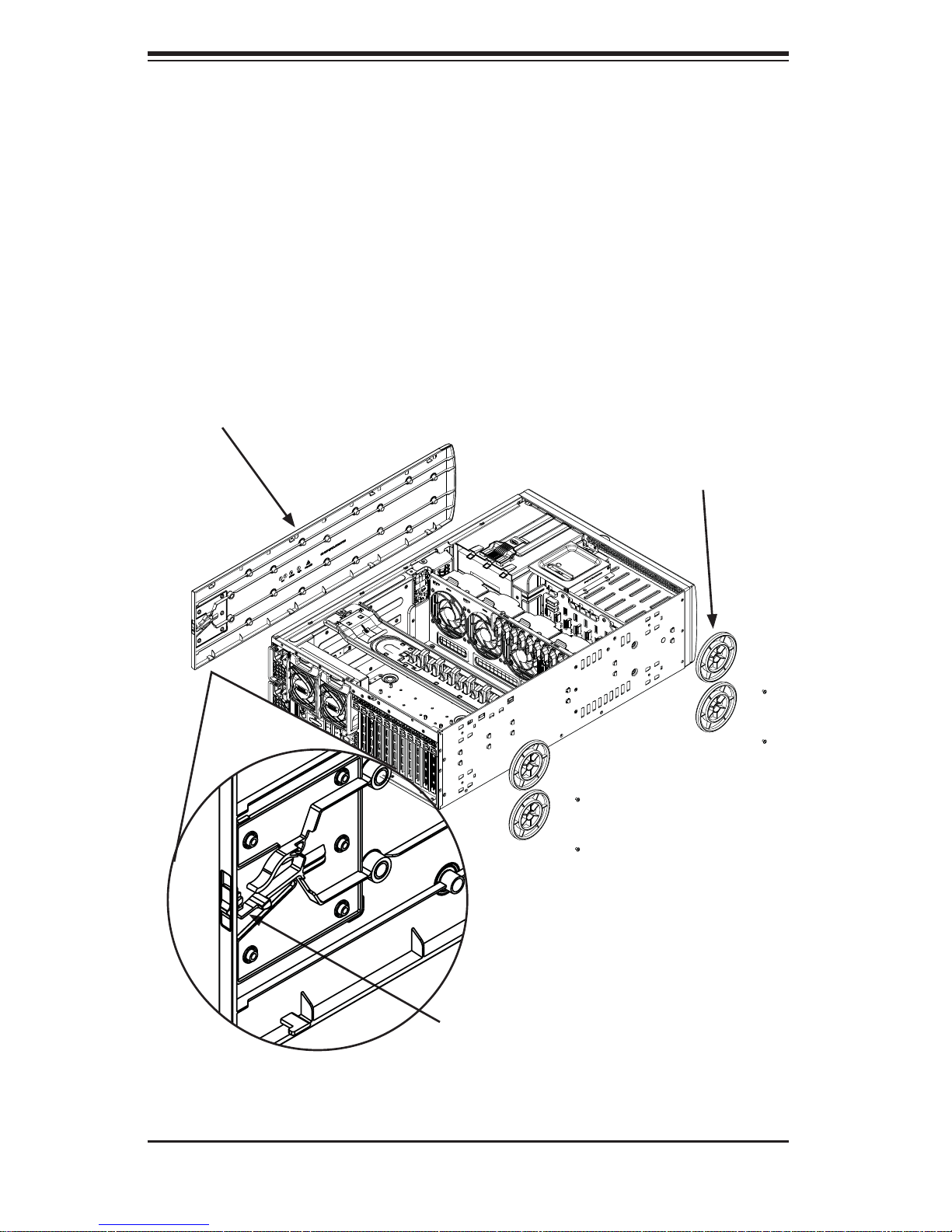
Removing the Chassis Cover and Feet
The SC747 chassis is shipped with the chassis cover and feet pre-installed. Both
the feet and cover must be removed for before installing the rails.
Chassis Cover
Chassis Feet
Figure 6-1: Removing the Feet and Chassis Top Cover
Chassis Cover Lock
2-6
Chapter 2: Server Installation
Removing the Chassis Top Cover
Locate the chassis cover lock (blue lever) at the rear of the chassis cover.1.
Slide the chassis cover lock to the right and push chassis cover forward.2.
Lift the chassis top cover off the chassis. 3.
Removing the Chassis Feet
Place the chassis on its side with the chassis side cover facing upward.1.
Remove the screw holding the chassis foot in place.2.
The foot lock is a tab located in the center of the foot that prevents the foot 3.
from sliding. Using a fl at head screwdriver, gently lift the foot lock upward
and slide the foot toward the rear of the chassis.
Repeat steps 2 and 3 with each remaining foot.4.
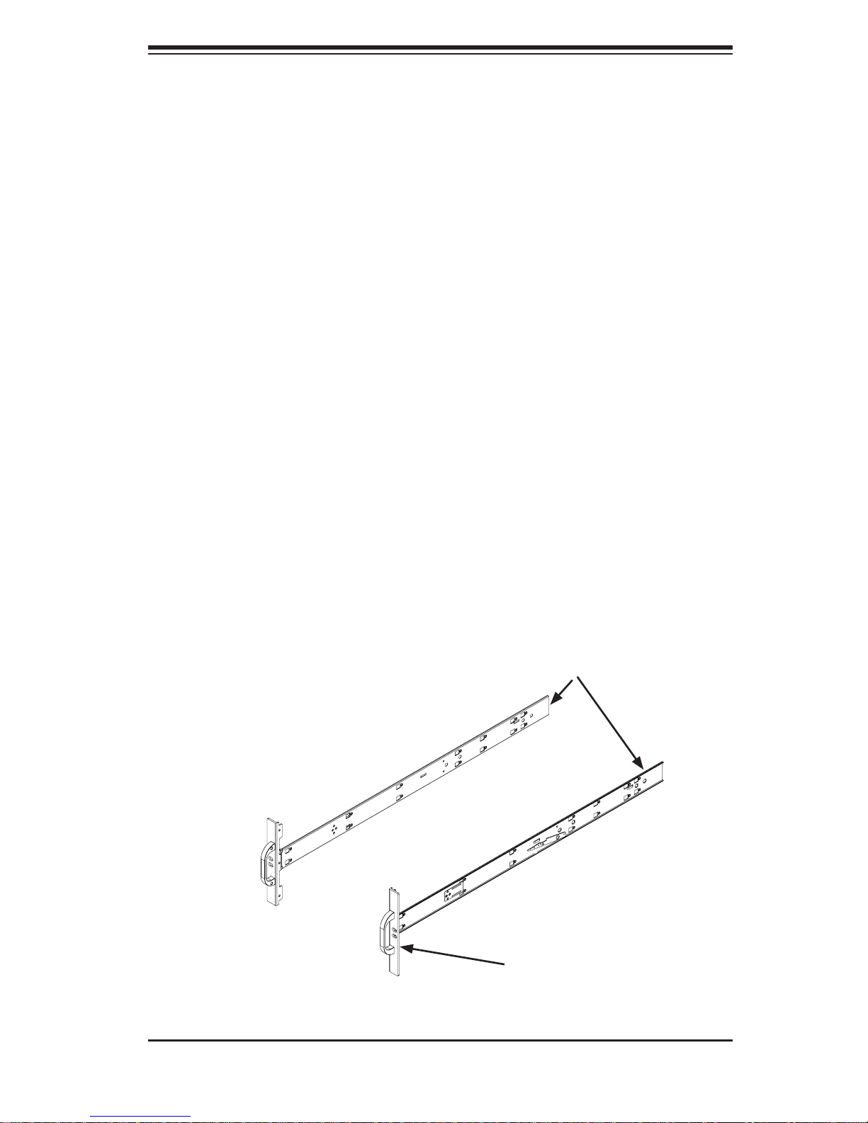
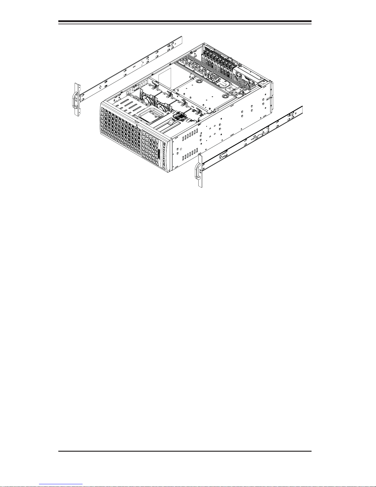
Identifying the Sections of the Rack Rails
The chassis package includes two rack rail assemblies in the rack mounting kit.
Each assembly consists of two sections: an inner fi xed chassis rail that secures
directly to the server chassis and an outer fi xed rack rail that secures directly to
the rack itself.
Inner Rails
Figure 6-2: Identifying the Inner Rails and Chassis Handles
Chassis Handle
2-7
SUPERSERVER AS-4021GA-62R+F User's Manual
Figure 6-3: Installing the Inner Rack Rails
Installing the Chassis Handles and Inner Rails
Installing the Inner Rails
Locate the chassis handles and handle screws.1.
Align the chassis handle with the front of the chassis and secure with the 2.
three chassis handle screws.
Repeats steps 1 and 2 with the other handle.3.
Locate the inner rails and screws in the shipping package.4.
Align the inner rails against the chassis, as shown. Confi rm that the rails are 5.
fl ushed against the edge of the chassis.
Tighten the screws. Do not over-tighten.6.
Repeat steps 5 and 6 with the other inner rail.7.
2-8
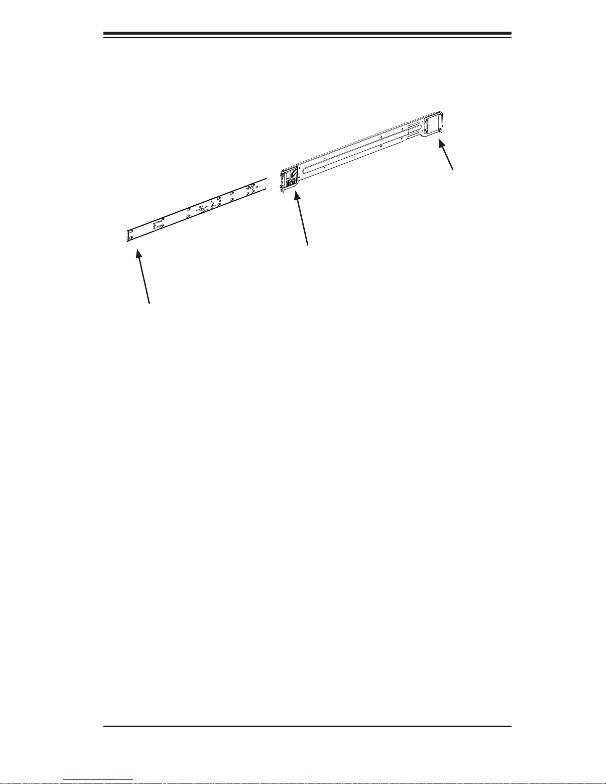
Attach to Middle Rail
Chapter 2: Server Installation
Secure to the
Rear of the Rack
Slide into the Inner Rail
Figure 6-4: Assembling the Outer Rails
Installing the Outer Rails to the Rack
Installing the Outer Rails
1. Attach the rear bracket to the middle bracket.
2. Adjust both the brackets to the proper distance so that the rail fi ts snugly into
the rack.
3. Secure the rear of the outer rail with two M5 screws and the rear of the rack.
NOTE: The outer rail is adjustable from approximately 26" to 38.25".
4. Repeat steps 1-3 for the left outer rail.
2-9
SUPERSERVER AS-4021GA-62R+F User's Manual
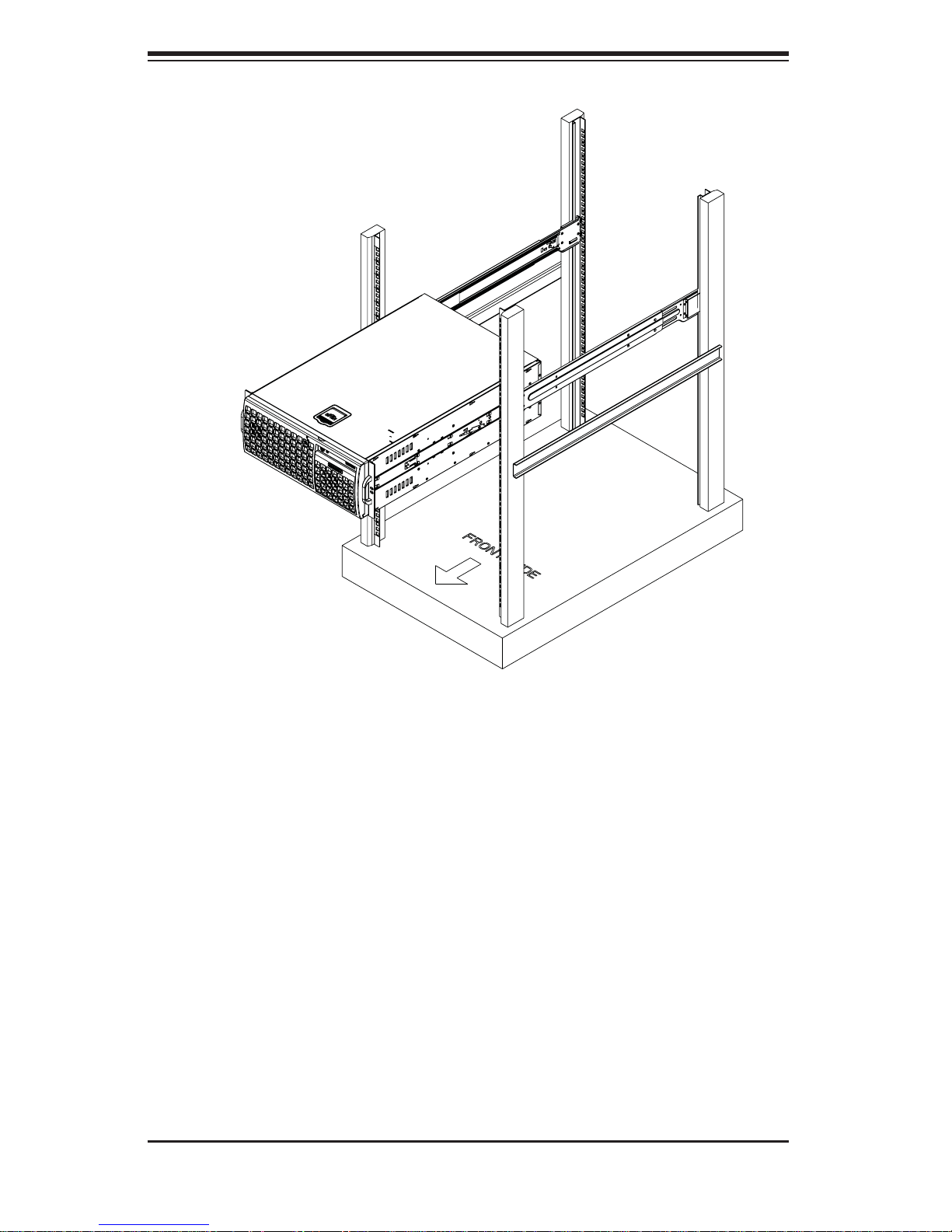
Figure 6-5: Installing the Rack Rails
Installing the Chassis into a Rack
Installing the Chassis
1. Confi rm that chassis includes the inner rails and the outer rails.
2. Align the inner chassis rails with the front of the outer rack rails (C).
3. Slide the inner rails into the outer rails, keeping the pressure even on both
sides (you may have to depress the locking tabs when inserting). When the
chassis has been pushed completely into the rack, you should hear the locking
tabs "click" into the locked position.
2-10
Chapter 2: Server Installation
2-6 Tower Mounting Instructions
The SC747 chassis is shipped with the chassis cover and feet pre-installed. To use
the chassis as a desktop server, no other installation is required.
Use the instructions in this section if you have converted the chassis for rack use
and need to return the chassis to tower mounting.
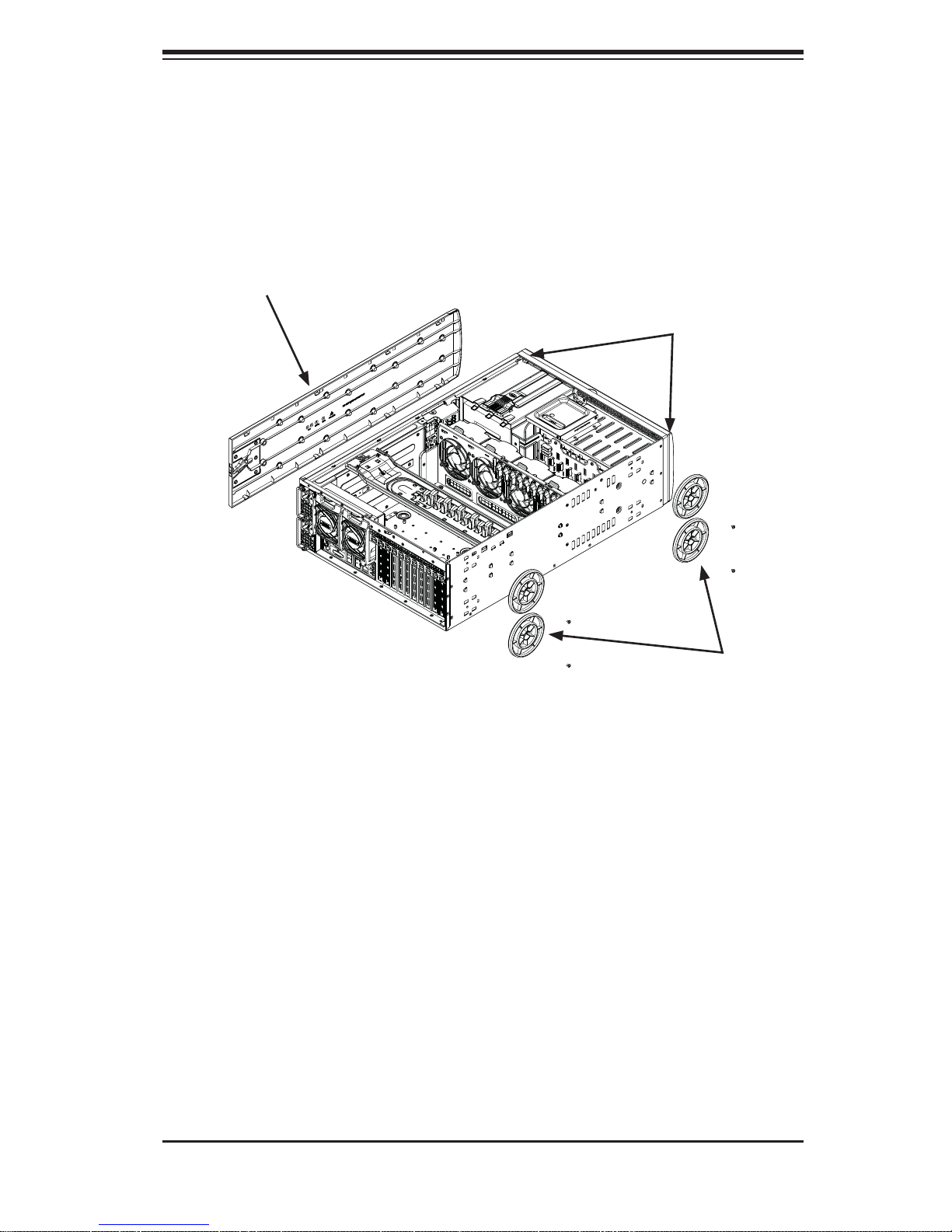
Chassis Cover
Chassis Rack Mount
Ears
Chassis Feet
Figure 6-6: Adding Chassis Feet and Top Cover
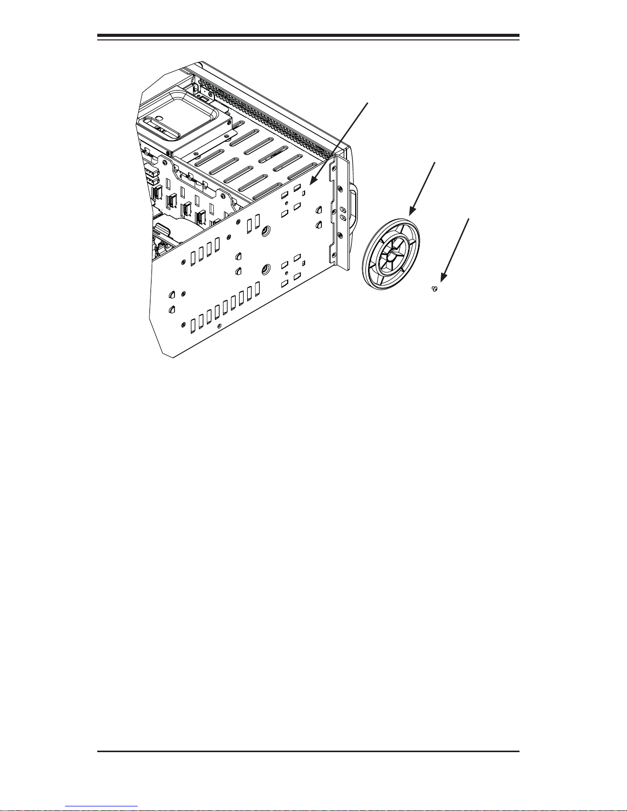
Installing the Chassis Cover
Installing the Cover
Remove the rack mount ears.1.
Align the cover post with the corresponding holes on the top of the chassis 2.
and place the cover on top of the chassis. The cover should overhang
approximately one-half inch over the front of the chassis.
Slide the chassis cover toward the rear of the chassis to lock the cover into 3.
place.
2-11
SUPERSERVER AS-4021GA-62R+F User's Manual
Chassis Foot
Receptacle
Chassis Foot
Chassis Screw
Figure 6-7: Placing Chassis Feet
Installing Feet on the Chassis
Installing the Chassis Feet
Place the chassis foot in the foot receptacle and slide the foot toward the 1.
front of the chassis. The foot should lock into place.
Secure the foot to the chassis using one screw enclosed in the packaging.2.
Repeat steps 1 and 2 for the remaining three chassis fee3.
2-12
Chapter 3: System Interface
Chapter 3
System Interface
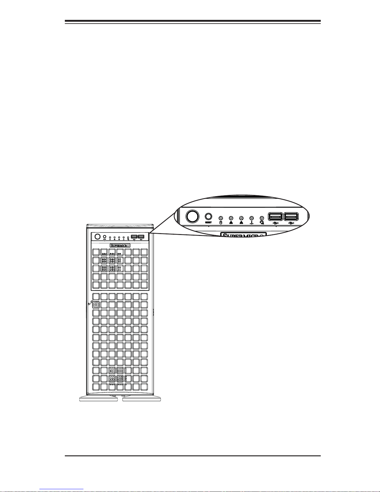
3-1 Overview
There are several LEDs on the control panel as well as others on the drive carriers
to keep you constantly informed of the overall status of the system as well as the
activity and health of specifi c components. Most SC747 models have two buttons
on the chassis control panel: a reset button and an on/off switch. This chapter explains the meanings of all LED indicators and the appropriate response you may
need to take.
Figure 4-1: Front LEDs
3-1
SUPERSERVER AS-4021GA-62R+F User's Manual
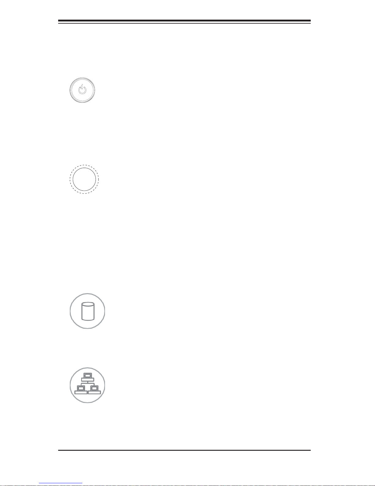
3-2 Control Panel Buttons
There are two push-buttons located on the front of the chassis. These are power
on/off button and a reset button.
Power:• The main power switch is used to apply or remove power from the power
supply to the server system. Turning off system power with this button removes
the main power but keeps standby power supplied to the system. Therefore,
you must unplug system before servicing.
Reset:• The reset button is used to reboot the system.
3-3 Control Panel LEDs
The control panel located on the front of the SC747 chassis has fi ve LEDs. These
LEDs provide you with critical information related to different parts of the system.
This section explains what each LED indicates when illuminated and any corrective
action you may need to take.
HDD:• Indicates IDE channel activity. SAS/SATA drive, SCSI drive, and/or DVD-
ROM drive activity when fl ashing.
NIC1:• Indicates network activity on GLAN1 when fl ashing.
3-2
 Loading...