

Supero SUPERSERVER 8047R-TRF+, SUPERSERVER 8047R-7RFT+ User Manual
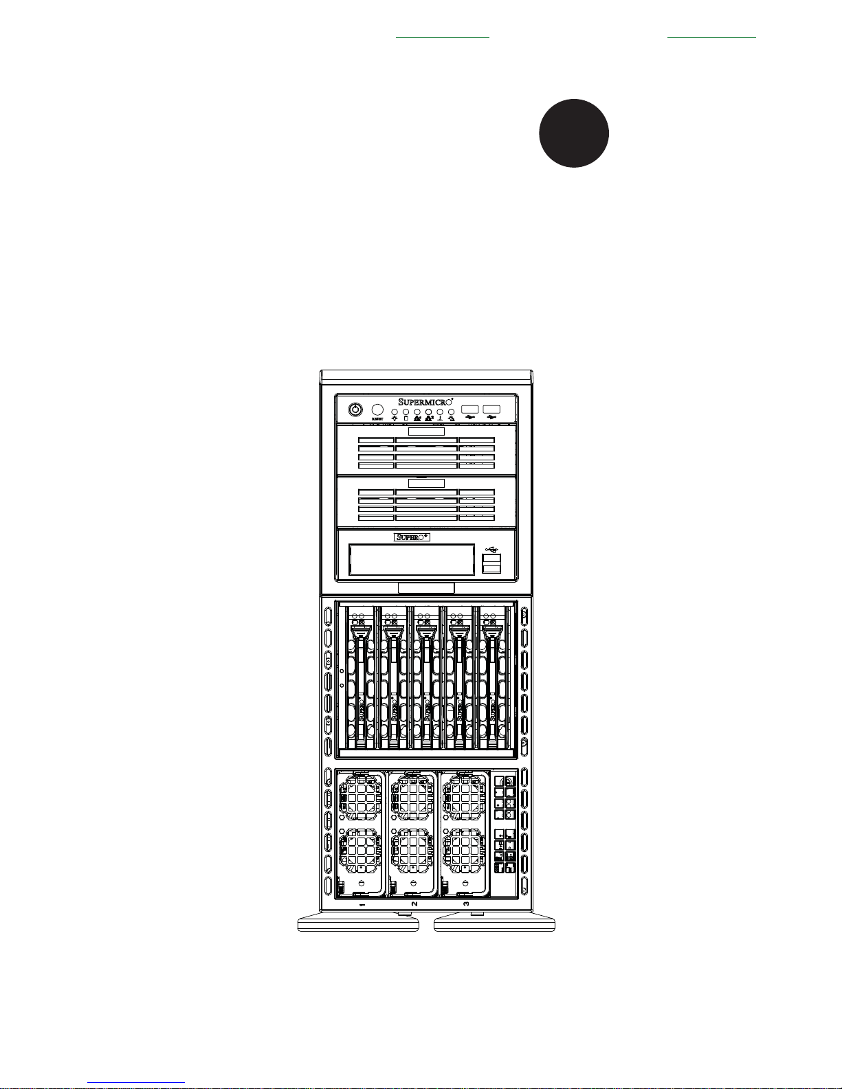
SUPERSERVER
8047R-TRF+
8047R-7RFT+
®
SUPER
USER'S MANUAL
Revision 1.0b
Проконсультироваться и купить данное оборудование вы можете в компании «АНД-Системс»
адрес: 125480, г.Москва, ул.Туристская, д.33/1; site: https://andpro.ru тел: +7 (495) 545-4870 email: info@andpro.ru
При обращении используйте промокод AND-PDF и получите скидку.

The information in this User’s Manual has been carefully reviewed and is believed to be accurate.
The vendor assumes no responsibility for any inaccuracies that may be contained in this document,
makes no commitment to update or to keep current the information in this manual, or to notify any
person or organization of the updates. Please Note: For the most up-to-date version of this
manual, please see our web site at www.supermicro.com.
Super Micro Computer, Inc. ("Supermicro") reserves the right to make changes to the product
described in this manual at any time and without notice. This product, including software and
documentation, is the property of Supermicro and/or its licensors, and is supplied only under a
license. Any use or reproduction of this product is not allowed, except as expressly permitted by
the terms of said license.
IN NO EVENT WILL SUPERMICRO BE LIABLE FOR DIRECT, INDIRECT, SPECIAL, INCIDENTAL,
SPECULATIVE OR CONSEQUENTIAL DAMAGES ARISING FROM THE USE OR INABILITY TO
USE THIS PRODUCT OR DOCUMENTATION, EVEN IF ADVISED OF THE POSSIBILITY OF
SUCH DAMAGES. IN PARTICULAR, SUPERMICRO SHALL NOT HAVE LIABILITY FOR ANY
HARDWARE, SOFTWARE, OR DATA STORED OR USED WITH THE PRODUCT, INCLUDING THE
COSTS OF REPAIRING, REPLACING, INTEGRATING, INSTALLING OR RECOVERING SUCH
HARDWARE, SOFTWARE, OR DATA.
Any disputes arising between manufacturer and customer shall be governed by the laws of Santa
Clara County in the State of California, USA. The State of California, County of Santa Clara shall
be the exclusive venue for the resolution of any such disputes. Super Micro's total liability for all
claims will not exceed the price paid for the hardware product.
FCC Statement: This equipment has been tested and found to comply with the limits for a Class
A digital device pursuant to Part 15 of the FCC Rules. These limits are designed to provide
reasonable protection against harmful interference when the equipment is operated in a commercial
environment. This equipment generates, uses, and can radiate radio frequency energy and, if not
installed and used in accordance with the manufacturer’s instruction manual, may cause harmful
interference with radio communications. Operation of this equipment in a residential area is likely
to cause harmful interference, in which case you will be required to correct the interference at your
own expense.
California Best Management Practices Regulations for Perchlorate Materials: This Perchlorate
warning applies only to products containing CR (Manganese Dioxide) Lithium coin cells. “Perchlorate
Material-special handling may apply. See www.dtsc.ca.gov/hazardouswaste/perchlorate”
WARNING: Handling of lead solder materials used in this
product may expose you to lead, a chemical known to
the State of California to cause birth defects and other
reproductive harm.
Manual Revision 1.0b
Release Date: July 03, 2014
Unless you request and receive written permission from Super Micro Computer, Inc., you may not
copy any part of this document.
Information in this document is subject to change without notice. Other products and companies
referred to herein are trademarks or registered trademarks of their respective companies or mark
holders.
Copyright © 2014 by Super Micro Computer, Inc.
All rights reserved.
Printed in the United States of America

iii
Preface
Preface
About This Manual
This manual is written for professional system integrators and PC technicians.
It provides information for the installation and use of the SuperServer
8047R-TRF+/7RFT+ Installation and maintainance should be performed by
experienced technicians only.
The SuperServer 8047R-TRF+/7RFT+ is a high-end server based on the
SC748TQ-R1K43BP 4U rackmount chassis and the X9QRi-F+/X9QR7-TF+ dual
processor serverboard. The only difference between the two server models is
that the 8047R-7RFT+ server contains both SATA and SAS connections and the
8047R-TRF+ server only has SATA connections.
Manual Organization
Chapter 1: Introduction
The fi rst chapter provides a checklist of the main components included with the
server system and describes the main features of the X9QRi-F+/X9QR7-TF+
serverboard and the SC748TQ-R1K43BP chassis.
Chapter 2: Server Installation
This chapter describes the steps necessary to install the SuperServer
8047R-TRF+/7RFT+ into a rack and check out the server confi guration prior to
powering up the system. If your server was ordered without processor and memory
components, this chapter will refer you to the appropriate sections of the manual
for their installation.
Chapter 3: System Interface
Refer here for details on the system interface, which includes the functions and
information provided by the control panel on the chassis as well as other LEDs
located throughout the system.
Chapter 4: System Safety
You should thoroughly familiarize yourself with this chapter for a general overview
of safety precautions that should be followed when installing and servicing the
SuperServer 8047R-TRF+/7RFT+.
Chapter 5: Advanced Serverboard Setup
Chapter 5 provides detailed information on the X9QRi-F+/X9QR7-TF+ serverboard,
including the locations and functions of connections, headers and jumpers. Refer
to this chapter when adding or removing processors or main memory and when
reconfi guring the serverboard.

SUPERSERVER 8047R-TRF+/7RFT+ USER'S MANUAL
iv
Chapter 6: Advanced Chassis Setup
Refer to Chapter 6 for detailed information on the SC748TQ-R1K43BP server
chassis. You should follow the procedures given in this chapter when installing,
removing or reconfi guring SAS/SATA or peripheral drives and when replacing
system power supply units and cooling fans.
Chapter 7: BIOS
The BIOS chapter includes an introduction to BIOS and provides detailed information
on running the CMOS Setup Utility for the X9QRi-F+/X9QR7-TF+ serverboard.
Appendix A: BIOS Error Beep Codes
Appendix B: Installing Windows
Appendix C: System Specifi cations

Notes
Preface
v

vi
Table of Contents
Chapter 1 Introduction
1-1 Overview ......................................................................................................... 1-1
1-2 Serverboard Features ..................................................................................... 1-2
Processors ...................................................................................................... 1-2
Memory ........................................................................................................... 1-2
Serial ATA ....................................................................................................... 1-2
SAS (8047R-7RFT+ Server Only) .................................................................. 1-3
Onboard Controllers/Ports .............................................................................. 1-3
Graphics Controller ......................................................................................... 1-3
Other Features ................................................................................................ 1-3
1-3 Server Chassis Features ................................................................................ 1-3
System Power ................................................................................................. 1-3
Hard Drive Subsystem .................................................................................... 1-4
Mobile Rack .................................................................................................... 1-4
Peripheral Drives ............................................................................................. 1-4
PCI Expansion Slots ....................................................................................... 1-4
Front Control Panel ......................................................................................... 1-4
I/O Backplane .................................................................................................. 1-4
Mounting Rails (optional) ................................................................................ 1-4
Cooling System ............................................................................................... 1-5
1-4 Advanced Power Management ....................................................................... 1-5
Intel® Intelligent Power Node Manager (NM) ................................................. 1-5
Manageability Engine (ME) ............................................................................. 1-5
1-5 Contacting Supermicro .................................................................................... 1-7
Chapter 2 Server Installation
2-1 Overview ......................................................................................................... 2-1
2-2 Unpacking the System .................................................................................... 2-1
2-3 Preparing for Setup ......................................................................................... 2-1
Choosing a Setup Location ............................................................................. 2-1
2-4 Cautions! ......................................................................................................... 2-2
Rack Precautions ............................................................................................ 2-2
Server Precautions .......................................................................................... 2-2
Rack Mounting Considerations ....................................................................... 2-3
Ambient Operating Temperature ................................................................ 2-3
Reduced Airfl ow ......................................................................................... 2-3
Mechanical Loading ................................................................................... 2-3
Circuit Overloading ..................................................................................... 2-3
SUPERSERVER 8047R-TRF+/7RFT+ USER'S MANUAL

vii
Reliable Ground ......................................................................................... 2-3
2-5 Installing the System into a Rack ................................................................... 2-4
Removing the Feet .......................................................................................... 2-4
Identifying the Sections of the Rack Rails ...................................................... 2-6
2-6 Tower Confi guration Instructions ....................................................................2-11
2-7 Checking the Serverboard Setup .................................................................. 2-12
2-8 Checking the Drive Bay Setup ...................................................................... 2-14
Chapter 3 System Interface
3-1 Overview ......................................................................................................... 3-1
Power .............................................................................................................. 3-2
Reset ............................................................................................................... 3-2
3-3 Control Panel LEDs ........................................................................................ 3-2
Power LED ...................................................................................................... 3-2
3-2 Control Panel Buttons ..................................................................................... 3-2
Universal Information LED .............................................................................. 3-3
HDD LED ........................................................................................................ 3-3
NIC2 LED ........................................................................................................ 3-3
NIC1 LED ........................................................................................................ 3-3
Power Fail LED ............................................................................................... 3-3
3-4 Drive Carrier LEDs .......................................................................................... 3-4
Chapter 4 Standardized Warning Statements for AC Systems
4-1 About Standardized Warning Statements ....................................................... 4-1
Warning Defi nition ........................................................................................... 4-1
Installation Instructions .................................................................................... 4-4
Circuit Breaker ................................................................................................ 4-5
Power Disconnection Warning ........................................................................ 4-6
Equipment Installation ..................................................................................... 4-8
Restricted Area ................................................................................................ 4-9
Battery Handling ............................................................................................ 4-10
Redundant Power Supplies .......................................................................... 4-12
Backplane Voltage ........................................................................................ 4-13
Comply with Local and National Electrical Codes ........................................ 4-14
Product Disposal ........................................................................................... 4-15
Hot Swap Fan Warning ................................................................................. 4-16
Power Cable and AC Adapter ...................................................................... 4-18
Table of Contents

viii
Chapter 5 Advanced Serverboard Setup
5-1 Handling the Serverboard ............................................................................... 5-1
Precautions ..................................................................................................... 5-1
Unpacking ....................................................................................................... 5-1
5-2 Connecting Cables .......................................................................................... 5-2
Connecting Data Cables ................................................................................. 5-2
Connecting Power Cables .............................................................................. 5-2
Connecting the Control Panel ......................................................................... 5-2
5-3 I/O Ports .......................................................................................................... 5-3
5-4 Installing the Processor and Heatsink ............................................................ 5-4
Installing the LGA2011 Processor ................................................................... 5-4
Installing a Passive CPU Heatsink ................................................................. 5-8
Removing the Heatsink ................................................................................... 5-9
5-5 Installing Memory .......................................................................................... 5-10
Memory Support ............................................................................................ 5-10
Processor & Memory Module Population Confi guration ................................5-11
Populating Memory Modules......................................................................... 5-12
Other Important Notes and Restrictions................................................... 5-18
5-6 Adding PCI-E Add-On Cards ........................................................................ 5-18
5-7 Serverboard Details ...................................................................................... 5-19
5-8 Connector Defi nitions ................................................................................... 5-21
5-9 Jumper Settings ............................................................................................ 5-28
Explanation of Jumpers ................................................................................ 5-28
5-10 Onboard Indicators ........................................................................................ 5-30
5-11 SAS/SATA Ports ............................................................................................ 5-32
5-12 Installing Software ......................................................................................... 5-33
SuperDoctor III .............................................................................................. 5-34
5-13 Serverboard Battery ...................................................................................... 5-36
Chapter 6 Advanced Chassis Setup
6-1 Static-Sensitive Devices .................................................................................. 6-1
Precautions ..................................................................................................... 6-1
Unpacking ....................................................................................................... 6-1
6-2 Control Panel .................................................................................................. 6-2
6-3 Confi guring the Storage Module ..................................................................... 6-3
Tower or Rack Confi guration........................................................................... 6-3
Adding Drives to the Storage Module ............................................................. 6-5
Adding Five Hard Drives to a Supermicro Mobile Rack: ................................ 6-8
6-4 Installing Hard Drives .................................................................................... 6-10
SUPERSERVER 8047R-TRF+/7RFT+ USER'S MANUAL

Add-on Card/Expansion Slot Setup .............................................................. 6-12
6-5 Installing the Air Shroud ................................................................................ 6-14
6-6 System Fans ................................................................................................. 6-15
Replacing a Front Chassis Fan .................................................................... 6-15
Replacing a Rear Chassis Fan ..................................................................... 6-16
6-7 Power Supply ............................................................................................... 6-17
Power Supply Failure .................................................................................... 6-17
Chapter 7 BIOS
7-1 Introduction ...................................................................................................... 7-1
Starting the Setup Utility ................................................................................. 7-1
7-2 Main Menu ...................................................................................................... 7-1
7-3 Advanced Settings Menu ................................................................................ 7-2
7-4 Event Logs .................................................................................................... 7-24
7-5 IPMI ............................................................................................................... 7-26
7-6 Boot ............................................................................................................... 7-28
7-7 Security ......................................................................................................... 7-28
7-8 Save & Exit ................................................................................................... 7-29
Appendix A BIOS Error Beep Codes
Appendix B System Specifi cations
ix
Table of Contents

Notes
x
SUPERSERVER 8047R-TRF+/7RFT+ USER'S MANUAL
Chapter 1
Introduction
1-1 Overview
The SuperServer 8047R-TRF+/7RFT+ is a high-end server comprised of
two main subsystems: the SC748TQ-R1K43BP 4U server chassis and the
X9QRi-F+/X9QR7-TF+ dual processor serverboard. Please refer to our web site for
information on operating systems that have been certifi ed for use with the system
(www.supermicro.com).
In addition to the serverboard and chassis, various hardware components have been
included with the SuperServer 8047R-TRF+/7RFT+, as listed below:
• Four (4) 2U passive CPU heatsinks (SNK-P0048PS)
• One (1) air shroud for SC748 (MCP-310-74805-0B)
• Chassis Fans
Three (3) 92x92x38 mm, 7.5K RPM, PWM fans for SC748 (FAN-0115L4)
Three (3) 80x80x38-mm 8.2K RPM, PWM fans for SC748 (FAN-0116L4)
• One (1) 77-cm USB 2.0 10p to 10p cable (CBL-0263L)
• One (1) 50-cm round 16-to-16-pin ribbon front panel control cable
(CBL-0087)
• SAS/SATA Accessories
One (1) SAS/SATA backplane (CSE-SAS-M35TQ-O-P)
Two (2) 61.5-cm 8pin to 8pin cables for SGPIO (CBL-0157L-01) (8047R-TRF+
only)
Five (5) 61-cm SATA cables (CBL-0044L) (8047R-TRF+ only)
Two (2) 30AWG 50-cm I-pass to 4 SATA connection cables (CBL-0097L-03)
(8047R-7RFT+ only)
Two (2) 5.25" drive trays without rail (horizontal pattern) (MCP-220-00010-01)
One (1) 5.25" drive tray without rail (FDD opening) (MCP-220-00059-0B)
One (1) black disk array mobile rack (CSE-M35BP) w/5 3.5" drive trays
(MCP-220-00092-0B)
Note: For your system to work properley, please follow the links below to download
all necessary drivers/utilities and the user's manual for your server.
• SMCI product manuals: http://www.supermicro.com/support/manuals/
• Product drivers and utilities: ftp://ftp.supermicro.com
Chapter 1: Introduction
1-1

1-2
SUPERSERVER 8047R-TRF+/7RFT+ USER'S MANUAL
• If you have any questions, please contact our support team at support@
supermicro.com
1-2 Serverboard Features
At the heart of the SuperServer 8047R-TRF+/7RFT+ lies the X9QRi-F+/X9QR7-TF+,
a dual processor serverboard based on the Intel C602 chipset. Below are the main
features of the X9QRi-F+/X9QR7-TF+. (See Figure 1-1 for a block diagram of the
chipset).
Processors
The X9QRi-F+/X9QR7-TF+ supports E5-4600 (V2) Series processors in
Socket R-LGA 2011 type sockets. Each processor supports two full-width Intel
QuickPath Interconnect (QPI) links (Data Transfer Rate of up to 8.0 GT/s per
direction) Please refer to our web site for a complete listing of supported processors
(www.supermicro.com).
Note: In order to install the E5-4600 (V2) Series CPU, you must make sure that
BIOS 3.0 version is installed to your system.
Memory
The X9QRi-F+/X9QR7-TF+ has thirty-two (32) single/dual/
tri/quad channel 240-pin DIMM sockets that can support up to 1024GB
of Registered (RDIMM), Load Reduced (LRDIMM) ECC or Unbuffered
(UDIMM) ECC/Non-ECC DDR3 1866/1600/1333/1066/800 MHz speed
SDRAM in a two-channel memory bus. Memory sizes of
1GB, 2GB, 4GB, 8GB, 16GB and 32GB size @ 1.35V/1.5V voltages are
supported. Please refer to Chapter 5 for installing memory.
Serial ATA
An on-chip (Intel C602) SATA controller is integrated into the X9QRi-F+/X9QR7-TF+
to provide a six-port SATA subsystem (two SATA 3.0 and four SATA 2.0 ports),
which is either RAID 0 and 1 (SATA3) or RAID 0, 1, 5, and 10 (SATA2) Windows/
LINUX supported. The SATA drives are hot-swappable units.
Note: You must have RAID set up to enable the hot-swap capability of the SATA
drives. Documentation on RAID setup guidelines can be found on our web site.

Chapter 1: Introduction
1-3
SAS (8047R-7RFT+ Server Only)
A LSI® 2208 SAS controller is integrated into the serverboard to provide an eight port
SAS (Serial Attached SCSI) subsystem, which is RAID 0, 1, 5, 6 and 10 supported.
The SAS drives are hot-swappable units.
Note: The operating system you use must have RAID support to enable the
hotswap capability and RAID function of the SAS drives.
Onboard Controllers/Ports
The color-coded I/O ports on the X9QRi-F+/X9QR7-TF+ include two COM ports
(one header and one port), a VGA (monitor) port, seven USB 2.0 ports (four rear
access I/O panel, front access (2x dual port connector and 1x single-connection
header), 1x Type-A connection for the two front panel), two gigabit Ethernet ports
and one dedicated IPMI LAN port.
Note 1: For more information on IPMI confi guration, please refer to the IPMI User's
Guide posted on our website at http://www.supermicro.com/support/manuals/
Graphics Controller
The X9QRi-F+/X9QR7-TF+ features an integrated Nuvoton (Winbond) BMC Video
Controller (Matrox MGA200).
Other Features
Other onboard features that promote system health include onboard voltage
monitors, auto-switching voltage regulators, chassis and CPU overheat sensors,
ACPI/ACPM power management, PECI (Platform Environment Confi guration
Interface) 2.0 support, AC power loss recovery, virus protection and BIOS rescue.
1-3 Server Chassis Features
The SuperServer 8047R-TRF+/7RFT+ is built upon the SC748TQ-R1K43BP
chassis. Details on the chassis and on servicing procedures can be found in Chapter
6. The following is a general outline of the main features of the chassis.
System Power
The SC748TQ-R1K43BP chassis features a redundant 1400 Watt Platinum level
digital power supply consisting of two power modules. The system does not need
to be shut down when replacing or removing a single power supply module.

1-4
SUPERSERVER 8047R-TRF+/7RFT+ USER'S MANUAL
Hard Drive Subsystem
The SC748TQ-R1K43BP chassis was designed to support fi ve 3.5" hot-swap SATA
or SAS hard drives in a M35 mobile rack, with an additional fi ve 3.5" hard drives
available with a second optional M35 mobile rack installed.
Mobile Rack
The SC748 chassis includes a CSE-M35BP mobile rack. The chassis contians a
space in the front for an additional mobile rack to be installed also. For detailed
specifi c to your mobile rack, information, see the appendices at the back of this
manual.
Peripheral Drives
Each SC748 chassis provides three 5.25” peripheral drive bays for DVD-ROM/
CD-ROM drives, or additional hard drives. One of these drive bays may be used
for a slim fl oppy drive.
PCI Expansion Slots
Four PCI expansion card slots are available in the rear of the chassis for two (2)
PCI Express 3.0 x16 slots (Slot3/Slot5) and two (2) PCI Express 3.0 x8 in x 16 slots
(Slot2/Slot4). See our web site for details (http://www.supermicro.com/products/nfo/
UIO.cfm). See section 5-6 for further details.)
Front Control Panel
The control panel on the SuperServer 8047R-TRF+/7RFT+ provides you with
system monitoring and control. LEDs indicate system power, HDD activity, network
activity, system overheat and power supply failure. A main power button and a
system reset button are also included. In addition, two USB ports have been
incorporated into the control panel to provide front side USB access.
I/O Backplane
The SC748TQ-R1K43BP 4U chassis contains an I/O backplane that provides four
standard-size add-on card slots, one COM port, a VGA port, four USB 2.0 ports, a
dedicated IPMI LAN port, two gigabit Ethernet ports and a UID switch.
Mounting Rails (optional)
The SC748 can be placed in a rack for secure storage and use. To setup your rack,
follow the step-by-step instructions included in this manual.

Chapter 1: Introduction
1-5
Cooling System
The SC748TQ-R1K43BP chassis has an innovative cooling design that includes
three 8-cm and three 9.2-cm hot-plug system cooling fans located in the middle
section of the chassis. An air shroud channels the airfl ow from the system fans to
effi ciently cool the processor area of the system. The power supply module also
includes a cooling fan.
1-4 Advanced Power Management
Intel® Intelligent Power Node Manager (NM)
The Intel® Intelligent Power Node Manager (IPNM) provides your system with
real-time thermal control and power management for maximum energy effi ciency.
Although IPNM Specifi cation Version 1.5 is supported by the BMC (Baseboard
Management Controller), your system must also have IPNM-compatible
Manageability Engine (ME) fi rmware installed to use this feature.
Manageability Engine (ME)
The Manageability Engine, which is an ARC controller embedded in the IOH (I/O
Hub), provides Server Platform Services (SPS) to your system. The services
provided by SPS are different from those proveded by the ME on client platforms.
1-6
SUPERSERVER 8047R-TRF+/7RFT+ USER'S MANUAL
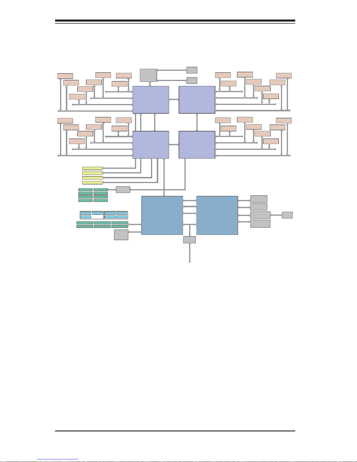
Figure 1-1. Intel C602 Chipset:
System Block Diagram
Note: This is a general block diagram. Please see Chapter 5 for details.
Romley EX
CPU4
E5-4600
130W/95W
CPU3
E5-4600
130W/95W
Romley EX
QPI
8GT/s
QPI 8GT/s
QPI 8GT/s
FAN Control
Romley EX
Patsburg A
C602
Windbond
BMC
CPU1
E5-4600
130W/95W
CPU2
E5-4600
130W/95W
Romley EX
QPI
8GT/s
DDR3-DMM
DDR3-1066/1333/1600 CHA
DDR3-1066/1333/1600 CHB
DDR3-1066/1333/1600 CHC
DDR3-1066/1333/1600 CHD
1066/1333/1600
DDR3-DMM
1066/1333/1600
DDR3-DMM
1066/1333/1600
DDR3-DMM
1066/1333/1600
DDR3-DMM
1066/1333/1600
DDR3-DMM
1066/1333/1600
DDR3-DMM
1066/1333/1600
DDR3-DMM
1066/1333/1600
DDR3-DMM
1066/1333/1600
DDR3-DMM
1066/1333/1600
DDR3-DMM
1066/1333/1600
DDR3-DMM
1066/1333/1600
DDR3-DMM
1066/1333/1600
DDR3-DMM
1066/1333/1600
DDR3-1066/1333/1600 CHA
DDR3-1066/1333/1600 CHB
DDR3-1066/1333/1600 CHC
DDR3-1066/1333/1600 CHD
DDR3-DMM
1066/1333/1600
DDR3-DMM
1066/1333/1600
DDR3-DMM
1066/1333/1600
DDR3-DMM
1066/1333/1600
DDR3-DMM
1066/1333/1600
DDR3-DMM
1066/1333/1600
DDR3-DMM
1066/1333/1600
DDR3-DMM
1066/1333/1600
DDR3-1066/1333/1600 CHA
DDR3-1066/1333/1600 CHB
DDR3-1066/1333/1600 CHC
DDR3-1066/1333/1600 CHD
DDR3-DMM
1066/1333/1600
DDR3-DMM
1066/1333/1600
DDR3-DMM
DDR3-1066/1333/1600 CHA
DDR3-1066/1333/1600 CHB
DDR3-1066/1333/1600 CHC
DDR3-1066/1333/1600 CHD
1066/1333/1600
DDR3-DMM
1066/1333/1600
DDR3-DMM
1066/1333/1600
DDR3-DMM
1066/1333/1600
DDR3-DMM
1066/1333/1600
DDR3-DMM
1066/1333/1600
DDR3-DMM
1066/1333/1600
DDR3-DMM
1066/1333/1600
SLOT#2 PCIE-G3x8
SLOT#3 PCIE-G3x16
SLOT#4 PCIE-G3x8
SLOT#4 PCIE-G3x8
PCIE-G3x8 from CPU4_PE2C/D
PCIE-G3x16 from CPU4_PE3A/B/C/D
PCIE-G3x8 from CPU1_PE2A/B
PCIE-G3x16 from CPU1_PE3A/B/C/D
PCIE-G3x8 from CPU2_PE1A/B
10/100
LAN
RJ45
Video
Memory
Rear Video
Connector
PHY (10/100)
RTL 8201F
BMC FW Flash
(16MBytes)
LSI2208
HM
7904D
BIOS
Flash
(16MBytes)
REAR
USB 2.0
SATA
LPC
DDR2
Analog
Video
RMII
SPI
PCI
USB
SMBus
SPI
SAS
SAS 6G Port
SAS 6G Port
SAS 6G Port
SAS 6G Port
SAS 6G Port
SAS 6G Port
SAS 6G Port
SAS 6G Port
SATA3-6G Port
SATA3-6G Port
SATA2-3G Port
SATA2-3G Port
SATA2-3G Port
SATA2-3G Port
USB Port
USB Port
USB Port
USB Port
HDR 2x5
USB PortUSB Port
USB Port
Twinville
10Gbit/1G/1000BaseT
TX LAN
RJ45
RJ45
10Gbit/1G/1000BaseT
TX LAN
Dual 10GbE

Chapter 1: Introduction
1-7
1-5 Contacting Supermicro
Headquarters
Address: Super Micro Computer, Inc.
980 Rock Ave.
San Jose, CA 95131 U.S.A.
Tel: +1 (408) 503-8000
Fax: +1 (408) 503-8008
Email: marketing@supermicro.com (General Information)
support@supermicro.com (Technical Support)
Web Site:
www.supermicro.com
Europe
Address: Super Micro Computer B.V.
Het Sterrenbeeld 28, 5215 ML
's-Hertogenbosch, The Netherlands
Tel: +31 (0) 73-6400390
Fax: +31 (0) 73-6416525
Email: sales@supermicro.nl (General Information)
support@supermicro.nl (Technical Support)
rma@supermicro.nl (Customer Support)
Web Site:
www.supermicro.com
Asia-Pacifi c
Address: Super Micro Computer, Inc.
3F, No. 150, Jian 1st Rd.
Zhonghe Dist., New Taipei City 235
Taiwan (R.O.C)
Tel: +886-(2) 8226-3990
Fax: +886-(2) 8226-3992
Email: support@supermicro.com.tw
Web Site:
www.supermicro.com.tw

1-8
SUPERSERVER 8047R-TRF+/7RFT+ USER'S MANUAL
Notes
Chapter 2: Server Installation
2-1
Chapter 2
Server Installation
2-1 Overview
This chapter provides a quick setup checklist to get your SuperServer
8047R-TRF+/7RFT+ up and running. Following these steps in the order given
should enable you to have the system operational within a minimum amount of time.
This quick setup assumes that your system has come to you with the processors
and memory preinstalled. If your system is not already fully integrated with a
serverboard, processors, system memory etc., please turn to the chapter or section
noted in each step for details on installing specifi c components.
2-2 Unpacking the System
You should inspect the box the SuperServer 8047R-TRF+/7RFT+ was shipped in
and note if it was damaged in any way. If the server itself shows damage you should
fi le a damage claim with the carrier who delivered it.
Decide on a suitable location for the rack unit that will hold the SuperServer
8047R-TRF+/7RFT+. It should be situated in a clean, dust-free area that is well
ventilated. Avoid areas where heat, electrical noise and electromagnetic fi elds are
generated. You will also need it placed near a grounded power outlet. Read the
Rack and Server Precautions in the next section.
2-3 Preparing for Setup
The box the SuperServer 8047R-TRF+/7RFT+ was shipped in should include two
sets of rail assemblies, two rail mounting brackets and the mounting screws you
will need to install the system into the rack. Follow the steps in the order given to
complete the installation process in a minimum amount of time. Please read this
section in its entirety before you begin the installation procedure outlined in the
sections that follow.
Choosing a Setup Location
• Leave enough clearance in front of the rack to enable you to open the front door
completely (~25 inches) and approximately 30 inches of clearance in the back
of the rack to allow for suffi cient airfl ow and ease in servicing.
2-2
SUPERSERVER 8047R-TRF+/7RFT+ USER'S MANUAL
• This product is for installation only in a Restricted Access Location (dedicated
equipment rooms, service closets and the like).
• This product is not suitable for use with visual display work place devices
acccording to §2 of the the German Ordinance for Work with Visual Display Units.
2-4 Cautions!
Rack Precautions
• Ensure that the leveling jacks on the bottom of the rack are fully extended to
the fl oor with the full weight of the rack resting on them.
• In single rack installation, stabilizers should be attached to the rack. In multiple
rack installations, the racks should be coupled together.
• Always make sure the rack is stable before extending a component from the
rack.
• You should extend only one component at a time - extending two or more
simultaneously may cause the rack to become unstable.
Server Precautions
• Review the electrical and general safety precautions in Chapter 4.
• Determine the placement of each component in the rack before you install the
rails.
• Install the heaviest server components on the bottom of the rack fi rst, and then
work up.
• Use a regulating uninterruptible power supply (UPS) to protect the server from
power surges, voltage spikes and to keep your system operating in case of a
power failure.
• Allow any hot plug drives and power supply modules to cool before touching
them.
• Always keep the rack's front door and all panels and components on the servers
closed when not servicing to maintain proper cooling.
Chapter 2: Server Installation
2-3
Rack Mounting Considerations
Ambient Operating Temperature
If installed in a closed or multi-unit rack assembly, the ambient operating
temperature of the rack environment may be greater than the ambient temperature
of the room. Therefore, consideration should be given to installing the equipment
in an environment compatible with the manufacturer’s maximum rated ambient
temperature (Tmra).
Reduced Airfl ow
Equipment should be mounted into a rack so that the amount of airfl ow required
for safe operation is not compromised.
Mechanical Loading
Equipment should be mounted into a rack so that a hazardous condition does not
arise due to uneven mechanical loading.
Circuit Overloading
Consideration should be given to the connection of the equipment to the power
supply circuitry and the effect that any possible overloading of circuits might have
on overcurrent protection and power supply wiring. Appropriate consideration of
equipment nameplate ratings should be used when addressing this concern.
Reliable Ground
A reliable ground must be maintained at all times. To ensure this, the rack
itself should be grounded. Particular attention should be given to power supply
connections other than the direct connections to the branch circuit (i.e. the use of
power strips, etc.).
2-4
SUPERSERVER 8047R-TRF+/7RFT+ USER'S MANUAL
2-5 Installing the System into a Rack
This section provides information on installing the SC748 chassis into a rack unit
with the rails provided. There are a variety of rack units on the market, which
may mean the assembly procedure will differ slightly. You should also refer to the
installation instructions that came with the rack unit you are using.
NOTE: The outer rail is adjustable from 26" to 38.25".
Removing the Feet
The SC748 chassis is shipped with the chassis cover and feet pre-installed. Both
the feet and cover must be removed for before installing the rails (see Figure 2-1).
Removing the Chassis Top Cover
1. Locate the chassis cover lock (blue lever) at the rear of the chassis cover.
2. Slide the chassis cover lock to the right and push chassis cover forward.
3. Lift the chassis top cover off the chassis.
Removing the Chassis Feet
1. Place the chassis on its side with the chassis side cover facing upward.
2. Remove the screw holding the chassis foot in place.
3. The foot lock is a tab located in the center of the foot that prevents the foot
from sliding. Using a fl at head screwdriver, gently lift the foot lock upward
and slide the foot toward the rear of the chassis.
4. Repeat steps 2 and 3 with each remaining foot.
Chapter 2: Server Installation
2-5
Figure 2-1: Remove the Chassis Cover and Feet
Chassis Feet
Chassis Cover
Chassis Cover Lock
2-6
SUPERSERVER 8047R-TRF+/7RFT+ USER'S MANUAL
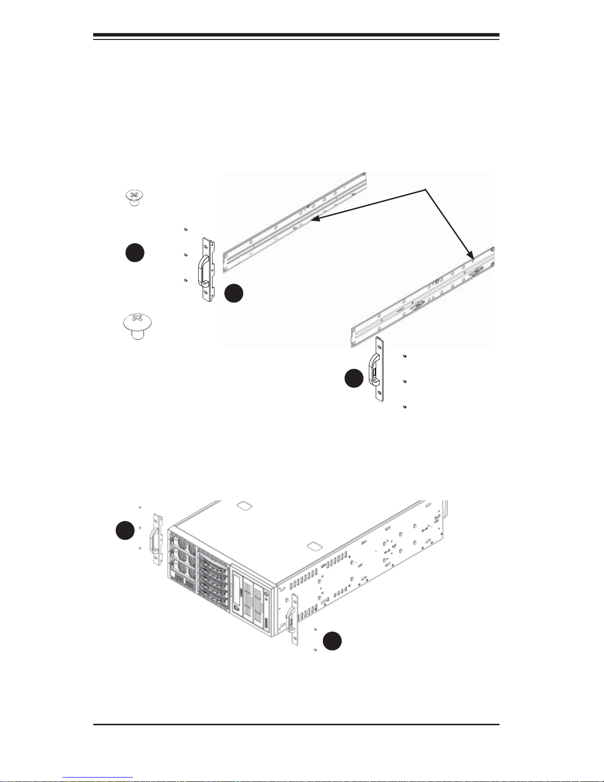
Figure 2-2: Identifying the Inner Rails and Chassis Handles
Chassis Handle
Inner Rails
Chassis Handle
Screw
Chassis Rail
Screw
Identifying the Sections of the Rack Rails
The chassis package includes two rack rail assemblies in the rack mounting kit.
Each assembly consists of two sections: an inner fi xed chassis rail that secures
directly to the server chassis and an outer fi xed rack rail that secures directly to the
rack itself (see Figure 2-2 for details).
Installing the Chassis Handles and Inner Rails
1. Locate the chassis handles (2) and handle screws (6) (Figure 2-3).
Figure 2-3: Identifying the Inner Rails and Chassis Handles
1
1
1
1
1
1
1
2
1
3
Chapter 2: Server Installation
2-7
Figure 2-4: Installing the Inner Rack Rails
2. Align the chassis handle with the front of the chassis and secure with the
three chassis handle screws.
3. Repeats steps 1 and 2 with the other handle.
4. Locate the inner rails (2) and screws (12) in the shipping package.
5. Align the inner rails against the chassis, as shown in Figure 2-4. Confi rm that
the rails are fl ushed against the edge of the chassis.
6. Tighten the screws. Do not over tighten.
7. Repeat steps 5 and 6 with the other inner rail.
2-8
SUPERSERVER 8047R-TRF+/7RFT+ USER'S MANUAL
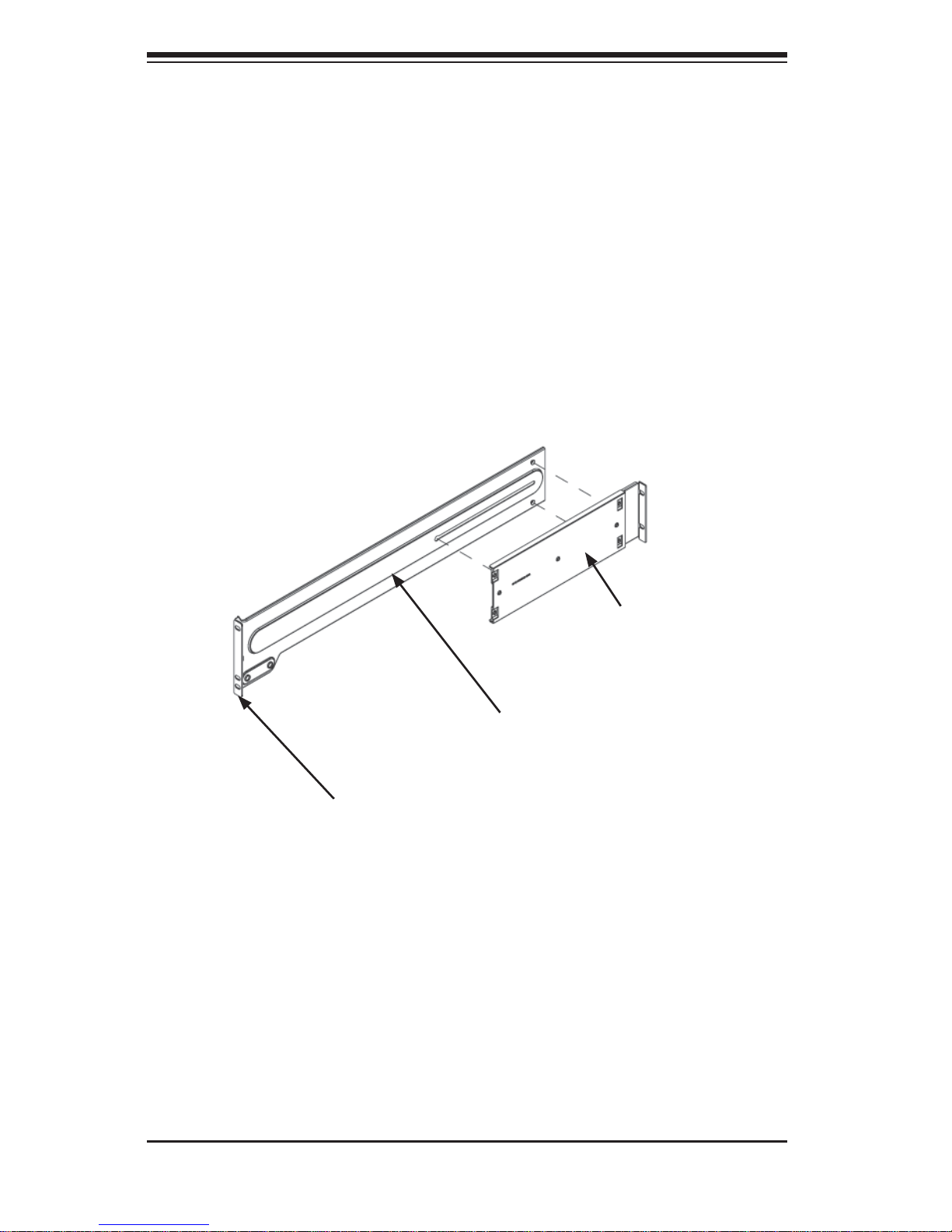
Installing the Outer Rails to the Rack (Figure 2-5)
1. Attach the front and rear short brackets to the outside of the long bracket.
Both bracket ends must face the same direction.
2. Adjust both the brackets to the proper distance so that the rail fi ts snugly into
the rack.
3. Secure the front side of the outer rail with two M5 screws and the rear side of
the outer rail with three M5 screws. NOTE: The outer rail is adjustable from
approximately 26" to 38.25".
4. Repeat steps 1-3 for the left outer rail.
Figure 2-5: Assembling the Outer Rails
Secure to the Front
of the Rack
Secure to the Rear
of the Rack
Attach to Rear Bracket
Chapter 2: Server Installation
2-9
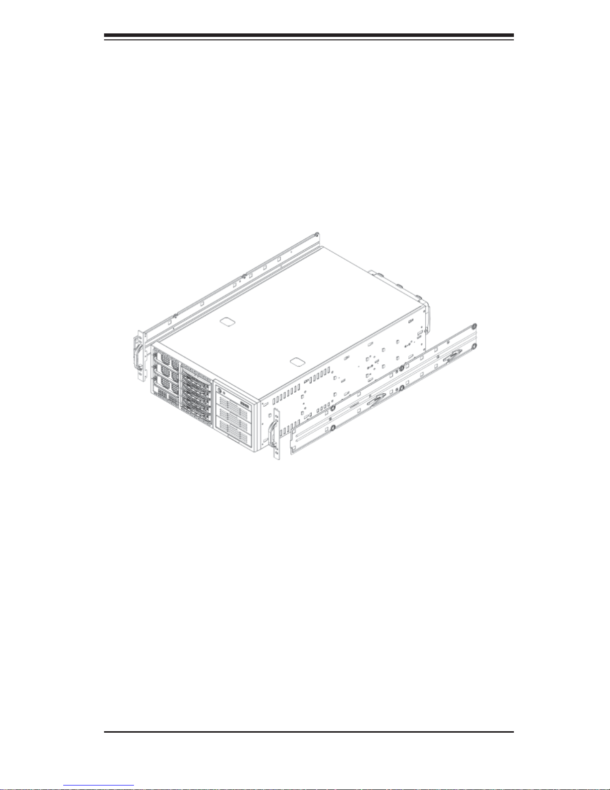
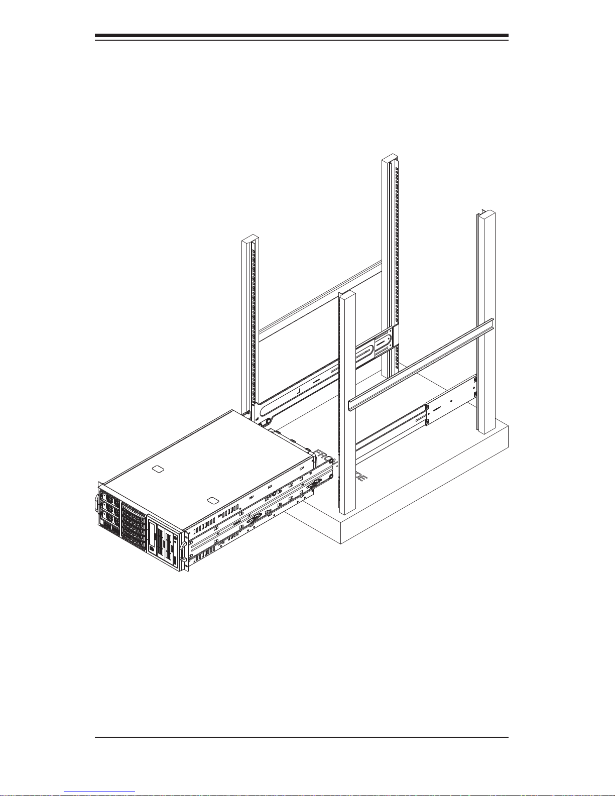
Installing the Chassis into a Rack
1. Confi rm that chassis includes the inner rails and the outer rails.
2. Line chassis rails with the front of the rack rails (Figure 2-6).
Figure 2-6. Installing the Rack Rails
2-10
SUPERSERVER 8047R-TRF+/7RFT+ USER'S MANUAL
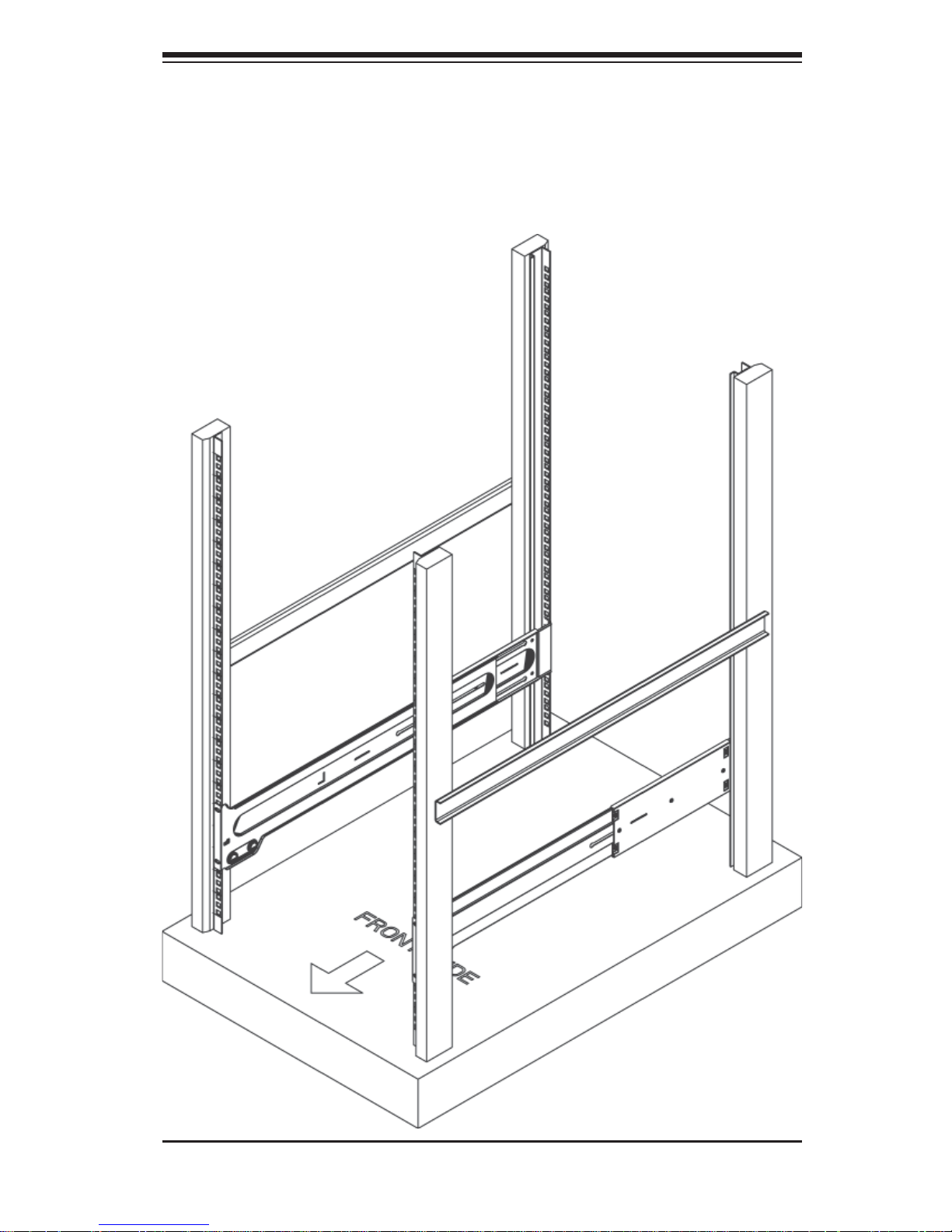
Figure 6-7: Installing the Chassis into a Rack
3. Slide the chassis rails into the rack rails, keeping the pressure even on both
sides (you may have to depress the locking tabs when inserting). When the
server has been pushed completely into the rack, you should hear the locking
tabs "click" (Figure 2-7).
Note: The fi gure above is for illustration purposes only. Always install servers to
the bottom of the rack fi rst.
Chapter 2: Server Installation
2-11
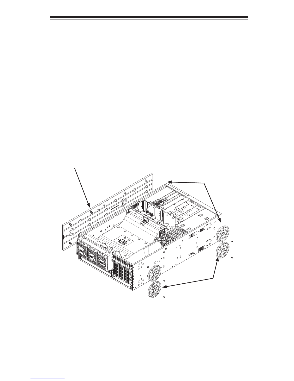
2-6 Tower Confi guration Instructions
The SC748 chassis is shipped with the chassis cover and feet pre-installed. To use
the chassis as a desktop server, no other installation is required.
Use the instructions in this section if you have converted the chassis for rack use
and need to return the chassis to tower mounting.
Installing the Chassis Cover
1. Remove the rack mount ears.
2. Align the cover post with the corresponding holes on the top of the chassis
and place the cover on top of the chassis. The cover should overhang
approximately one-half inch over the front of the chassis (Figure 2-8).
3. Slide the chassis cover toward the rear of the chassis to lock the cover into
place.
Figure 2-8: Adding the Chassis Feet and Top Cover
Add the
Chassis
Feet
Remove
Chassis Rack
Mount Ears
Add the
Chassis Cover
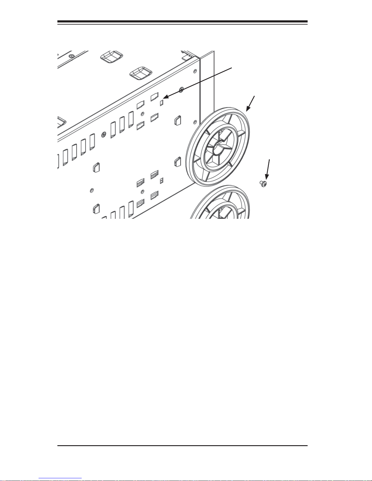
Placing the Chassis Feet (Figure 2-9)
1. Place the chassis foot in the foot receptacle and slide the foot toward the
front of the chassis. The foot should lock into place.
2. Secure the foot to the chassis using one screw enclosed in the packaging.
3. Repeat steps 1 and 2 for the remaining three chassis feet.
2-12
SUPERSERVER 8047R-TRF+/7RFT+ USER'S MANUAL
2-7 Checking the Serverboard Setup
After you setup the 8047R-TRF+/7RFT+ (in the rack or tower confi guration), you
will need to open the unit to make sure the serverboard is properly installed and
all the connections have been made.
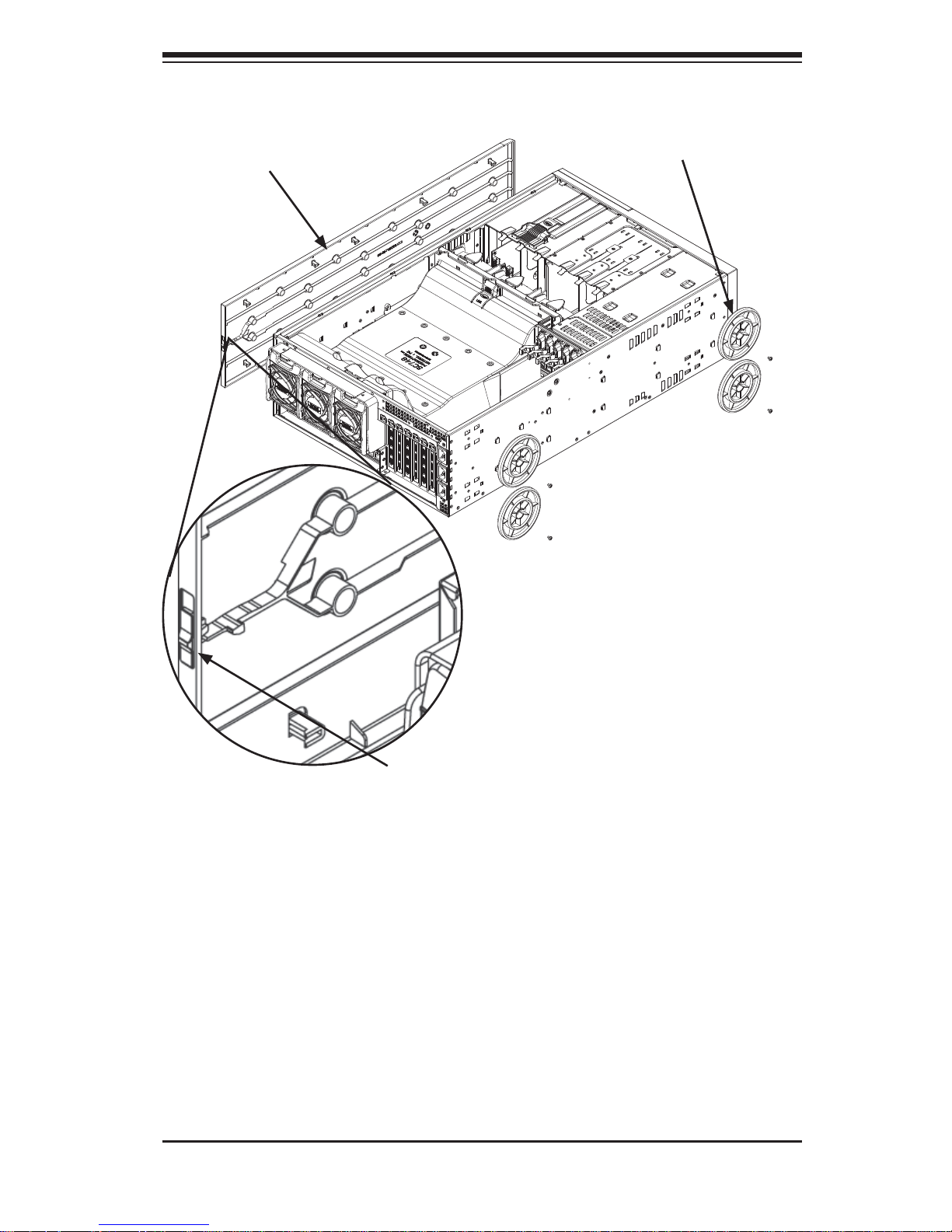
Removing the Chassis Cover (Figure 2-10)
1. Unplug the chassis from any power source
2. Remove the two screws securing the cover to the chassis.
3. Press the release tabs simultaneously.
4. Slide the cover forward.
Figure 2-9: Placing Chassis Feet
Chassis Foot
Receptacle
Chassis Foot
Chassis
Screw
 Loading...