

Page 1
SUPER
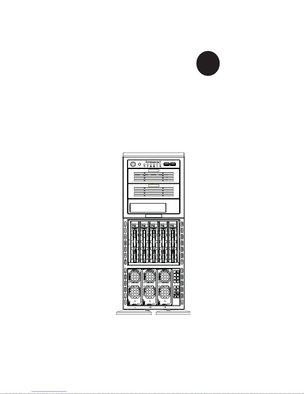
SUPERSERVER 8046B-6RF
SUPERSERVER 8046B-TRF
®
USER’S MANUAL
Revision 1.0
Page 2

The information in this User’s Manual has been carefully reviewed and is believed to be accurate.
The vendor assumes no responsibility for any inaccuracies that may be contained in this document,
makes no commitment to update or to keep current the information in this manual, or to notify any
person or organization of the updates. Please Note: For the most up-to-date version of this
manual, please see our web site at www.supermicro.com.
Super Micro Computer, Inc. ("Supermicro") reserves the right to make changes to the product
described in this manual at any time and without notice. This product, including software and documentation, is the property of Supermicro and/or its licensors, and is supplied only under a license.
Any use or reproduction of this product is not allowed, except as expressly permitted by the terms
of said license.
IN NO EVENT WILL SUPERMICRO BE LIABLE FOR DIRECT, INDIRECT, SPECIAL, INCIDENTAL,
SPECULATIVE OR CONSEQUENTIAL DAMAGES ARISING FROM THE USE OR INABILITY TO
USE THIS PRODUCT OR DOCUMENTATION, EVEN IF ADVISED OF THE POSSIBILITY OF
SUCH DAMAGES. IN PARTICULAR, SUPERMICRO SHALL NOT HAVE LIABILITY FOR ANY
HARDWARE, SOFTW ARE, OR DA TA STORED OR USED WITH THE PRODUCT, INCLUDING THE
COSTS OF REPAIRING, REPLACING, INTEGRATING, INSTALLING OR RECOVERING SUCH
HARDWARE, SOFTWARE, OR DATA.
Any disputes arising between manufacturer and customer shall be governed by the laws of Santa
Clara County in the State of California, USA. The State of California, County of Santa Clara shall
be the exclusive venue for the resolution of any such disputes. Super Micro's total liability for all
claims will not exceed the price paid for the hardware product.
FCC Statement: This equipment has been tested and found to comply with the limits for a Class A
digital device pursuant to Part 15 of the FCC Rules. These limits are designed to provide reasonable
protection against harmful interference when the equipment is operated in a commercial environment. This equipment generates, uses, and can radiate radio frequency energy and, if not installed
and used in accordance with the manufacturer’s instruction manual, may cause harmful interference
with radio communications. Operation of this equipment in a residential area is likely to cause harmful
interference, in which case you will be required to correct the interference at your own expense.
California Best Management Practices Regulations for Perchlorate Materials: This Perchlorate warning applies only to products containing CR (Manganese Dioxide) Lithium coin cells. “Perchlorate
Material-special handling may apply. See www.dtsc.ca.gov/hazardouswaste/perchlorate”
WARNING: Handling of lead solder materials used in this
product may expose you to lead, a chemical known to the
State of California to cause birth defects and other reproductive harm.
Manual Revision 1.0
Release Date: February 23, 2011
Unless you request and receive written permission from Super Micro Computer, Inc., you may not
copy any part of this document.
Information in this document is subject to change without notice. Other products and companies
referred to herein are trademarks or registered trademarks of their respective companies or mark
holders.
Copyright © 2011 by Super Micro Computer, Inc.
All rights reserved.
Printed in the United States of America
Page 3

Preface
About This Manual
This manual is written for professional system integrators and PC technicians. It
provides information for the installation and use of the SuperServer 8025C-3R. Installation and maintenance should be performed by experienced technicians only.
The SuperServer 8046B-6RF/8046B-TRF is a high-end quad processor server
based on the SC748TQ-R1400BP 4U tower/rackmount server chassis and the Super X8QB6-F/X8QBE-F serverboard. The X8QB6-F/X8QBE-F supports four Intel®
Xeon processors. Please refer to our web site for an up-to-date list of supported
processors.
Preface
Manual Organization
Chapter 1: Introduction
The fi rst chapter provides a checklist of the main components included with the
server system and describes the main features of the Super X8QB6-F/X8QBE-F
serverboard and the SC748TQ-R1400BP chassis.
Chapter 2: Server Installation
This chapter describes the steps necessary to install the server into a rack and
check out the server confi guration prior to powering up the system. If your server
was ordered without the processor and memory components, this chapter will refer
you to the appropriate sections of the manual for their installation.
Chapter 3: System Interface
Refer to this chapter for details on the system interface, which includes the functions
and information provided by the control panel on the chassis as well as other LEDs
located throughout the system.
iii
Page 4

SUPERSERVER 8046B-6RF/8046B-TRF User's Manual
Chapter 4: System Safety
You should thoroughly familiarize yourself with this chapter for a general overview
of safety precautions that should be followed when installing and servicing the
SuperServer 8046B-6RF/8046B-TRF.
Chapter 5: Advanced Serverboard Setup
Chapter 5 provides detailed information on the X8QB6-F/X8QBE-F serverboard,
including the locations and functions of connectors, headers and jumpers. Refer
to this chapter when adding or removing processors or main memory and when
reconfi guring the serverboard.
Chapter 6: Advanced Chassis Setup
Refer to Chapter 6 for detailed information on the SC748TQ-R1400BP 4U tower/
rackmount server chassis. You should follow the procedures given in this chapter
when installing, removing or reconfi guring SAS or peripheral drives and when re-
placing system power supply units and cooling fans.
Chapter 7: BIOS
The BIOS chapter includes an introduction to BIOS and provides detailed information on running the CMOS Setup Utility.
Appendix A: BIOS POST Codes
Appendix B: System Specifi cations
iv
Page 5

Notes
Preface
v
Page 6

SUPERSERVER 8046B-6RF/8046B-TRF User's Manual
Table of Contents
Chapter 1 Introduction
1-1 Overview .........................................................................................................1-1
1-2 Serverboard Features .....................................................................................1-2
Processors ......................................................................................................1-2
Memory ...........................................................................................................1-2
Serial Attached SCSI (X8QB6-F) ....................................................................1-2
Serial ATA .......................................................................................................1-2
PCI Expansion Slots ....................................................................................... 1-2
I/O Ports .......................................................................................................... 1-3
IPMI .................................................................................................................1-3
Other Features ................................................................................................ 1-3
1-3 Server Chassis Features ................................................................................1-4
System Power ................................................................................................. 1-4
SAS/SATA Subsystem .....................................................................................1-4
Front Control Panel .........................................................................................1-4
Cooling System ............................................................................................... 1-4
1-4 Contacting Supermicro ....................................................................................1-6
Chapter 2 Server Installation
2-1 Overview .........................................................................................................2-1
2-2 Unpacking the System .................................................................................... 2-1
2-3 Preparing for Setup .........................................................................................2-1
Rack Precautions .................................................................................................
Server Precautions ...............................................................................................
Choosing a Setup Location .............................................................................2-2
Rack Precautions ............................................................................................ 2-2
Server Precautions ..........................................................................................2-2
Rack Mounting Considerations .......................................................................2-3
Ambient Operating Temperature ................................................................ 2-3
Reduced Airfl ow .........................................................................................2-3
Mechanical Loading ................................................................................... 2-3
Circuit Overloading .....................................................................................2-3
Reliable Ground ......................................................................................... 2-3
2-4 Installing the System into a Rack ................................................................... 2-4
Removing the Chassis Cover and Feet ..........................................................2-4
Identifying the Sections of the Rack Rails ...................................................... 2-5
2-5 Checking the Serverboard Setup ....................................................................2-9
vi
Page 7

Table of Contents
2-6 Preparing to Power On ..................................................................................2-11
Chapter 3 System Interface
3-1 Overview .........................................................................................................3-1
3-2 Control Panel Buttons ..................................................................................... 3-1
Reset ...............................................................................................................3-1
Power ..............................................................................................................3-1
3-3 Control Panel LEDs ........................................................................................3-2
Power Fail .......................................................................................................3-2
Overheat/Fan Fail ........................................................................................... 3-2
NIC2 ................................................................................................................3-2
NIC1 ................................................................................................................3-3
HDD .................................................................................................................3-3
Power ..............................................................................................................3-3
3-4 Hard Drive Carrier LEDs ................................................................................. 3-4
Chapter 4 System Safety
4-1 Electrical Safety Precautions .......................................................................... 4-1
4-2 General Safety Precautions ............................................................................4-2
4-3 ESD Precautions ............................................................................................. 4-3
4-4 Operating Precautions .................................................................................... 4-4
Chapter 5 Advanced Serverboard Setup
5-1 Handling the Serverboard ............................................................................... 5-1
Precautions .....................................................................................................5-1
Unpacking .......................................................................................................5-2
5-2 Serverboard Installation ..................................................................................5-2
5-3 Connecting Cables .......................................................................................... 5-3
Connecting Data Cables ................................................................................. 5-3
Connecting Power Cables ..............................................................................5-3
Connecting the Control Panel ......................................................................... 5-3
5-4 I/O Ports ..........................................................................................................5-4
5-5 Installing the Processor and Heatsink ............................................................ 5-5
Installing an LGA 1567 Processor .......................................................................
Installing a Passive CPU Heatsink ................................................................. 5-6
Removing the Passive Heatsink .....................................................................5-7
Memory Support ..............................................................................................5-8
5-7 Adding PCI Add-On Cards ............................................................................5-10
5-8 Serverboard Details .......................................................................................5-11
X8QB6-F/X8QBE-F Quick Reference ........................................................... 5-12
5-9 Connector Defi nitions ................................................................................... 5-13
vii
Page 8

SUPERSERVER 8046B-6RF/8046B-TRF User's Manual
5-10 Jumper Settings ............................................................................................5-19
5-11 Onboard Indicators ........................................................................................5-21
5-12 SAS and SATA Ports .....................................................................................5-22
Chapter 6 Advanced Chassis Setup
6-1 Static-Sensitive Devices ..................................................................................6-1
Precautions .....................................................................................................6-1
Unpacking .......................................................................................................6-2
6-2 Control Panel ..................................................................................................6-3
6-3 System Fans ...................................................................................................6-4
Fan Failure ...................................................................................................... 6-4
Replacing System Fans ............................................................................. 6-4
6-4 Drive Bay Installation ......................................................................................6-6
Hard Drives .....................................................................................................6-6
SAS/SATA Backplane ......................................................................................6-6
Installing Components in the 5.25" Drive Bays .............................................. 6-8
6-5 Power Supply .................................................................................................. 6-9
Power Supply Failure ......................................................................................6-9
Removing/Replacing the Power Supply ..........................................................6-9
Chapter 7 BIOS
7-1 Introduction ......................................................................................................7-1
7-2 Main Setup ...................................................................................................... 7-2
7-3 Advanced Setup Confi gurations......................................................................7-4
7-3 Boot Confi guration ........................................................................................ 7-29
7-4 Security Settings ...........................................................................................7-30
7-5 Exit Options ................................................................................................... 7-31
Appendix A POST Codes
Appendix B System Specifi cations
viii
Page 9

Chapter 1: Introduction
Chapter 1
Introduction
1-1 Overview
The SuperServer 8046B-6RF/8046B-TRF is a high-end server comprised of two
main subsystems: the SC748TQ-R1400B 4U/tower chassis and the X8QB6-F/
X8QBE-F quad processor serverboard. Please refer to our web site for information
on operating systems that have been certifi ed for use with the 8046B-6RF/8046B-
TRF (www.supermicro.com).
In addition to the serverboard and chassis, various hardware components have
been included with the 8046B-6RF/8046B-TRF, as listed below:
Three chassis fans (FAN-0115L4)
•
Three rear exhaust fans (FAN-0116L4)•
Four passive heatsinks (SNK-P0045P)•
One air shroud (MCP-310-74803-0B) •
SAS/SATA Accessories •
One SAS backplane (BPN-SAS-M35TQ)
Five hot-swap hard drive carriers (CSE-PT17-B)
One SuperServer 8046B-6RF/8046B-TRF User's Manual
•
Optional: one rail kit (MCP-290-00059-0B)•
1-1
Page 10

SUPERSERVER 8046B-6RF/8046B-TRF User's Manual
1-2 Serverboard Features
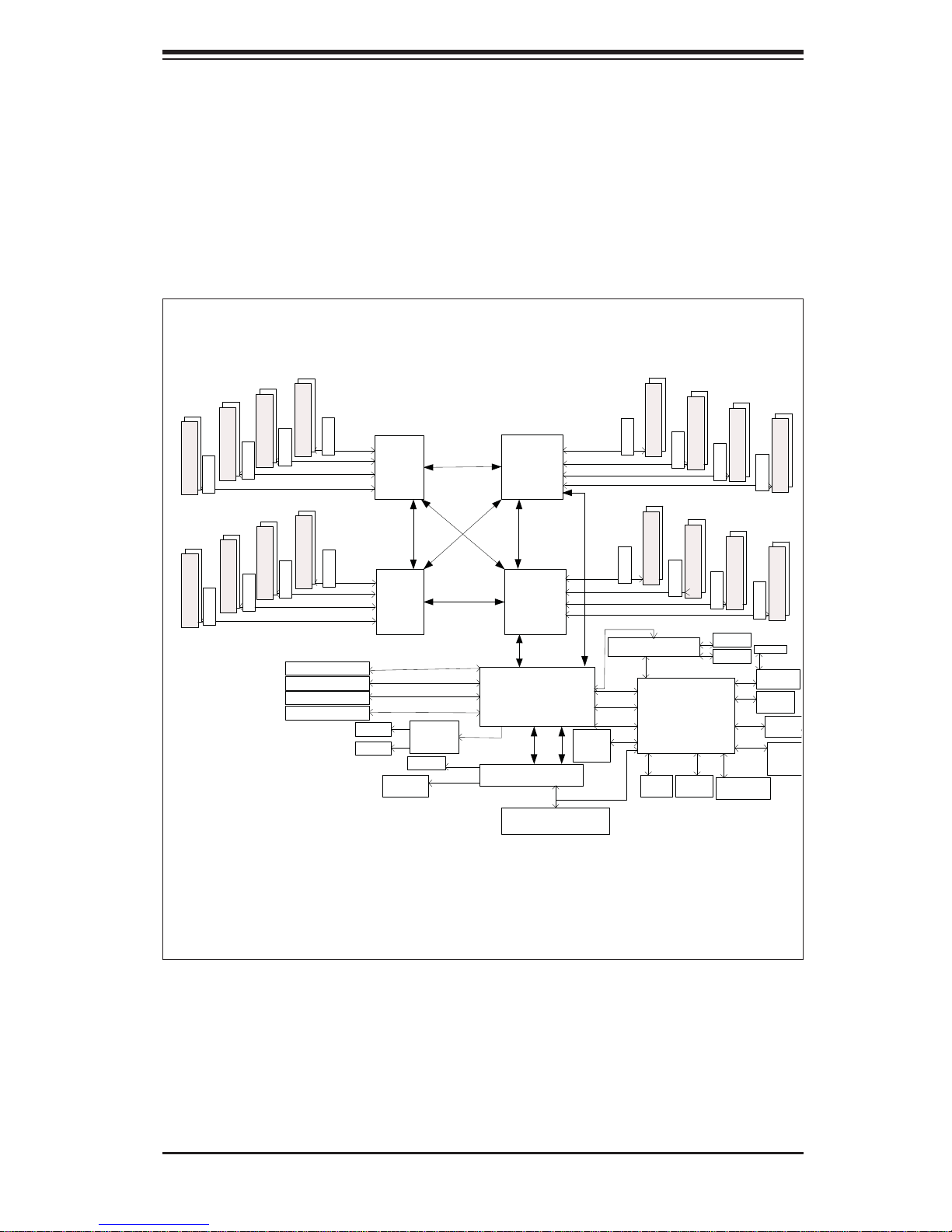
At the heart of the SuperServer 8046B-6RF/8046B-TRF lies the X8QB6-F/X8QBEF, a quad processor serverboard based on the Intel 7500 + ICH10R chipset. (See
Figure 1-1 for a block diagram of the chipset).
Processors
The X8QB6-F/X8QBE-F supports four Intel Xeon 7500 Series processors in 1567pin LGA sockets. Please refer to the serverboard description pages on our web site
for a complete listing of supported processors (www.supermicro.com).
Memory
The X8QB6-F/X8QBE-F can support up to 512 GB of registered ECC or unbuffered ECC DDR3-1333/1066/978/800 memory. (DDR-1333 memory will run at
1066 MHz.) Modules of the same size and speed should be used. See Chapter 5
Section 5 for details.
Serial Attached SCSI (X8QB6-F)
An onboard LSI 2108 Serial Attached SCSI (SAS) controller is integrated into the
X8QB6-F (only), which supports eight 6 Gbps SAS hard drives. The SAS drives are
connected to a backplane that provides power, bus termination and confi guration
settings and are hot-swappable units. Note: The operati ng system you use mu st
have RAID support to enable the hot-swap capabilit y and RAID funct ion of the
SAS drive s. R AID 0, 1, 5, 6, 10, 50 and 6 0 are sup por ted.
Serial ATA
A SATA controller is integrated into the South Bridge (ICH10R) section of the
chipset to provide a six-port 3 Gbps SATA subsystem, which is RAID 0, 1, 10
and 5 supported (RAID 5 supported by Windows only). The Serial ATA drives are
hot-swappable units.
PCI Expansion Slots
The X8QB6-F/X8QBE-F can support one of the following confi gurations.
two PCI-E 2.0 x16 slots
•
one PCI-E 2.0 x16 and two PCI-E 2.0 x8 slots•
four PCI-E 2.0 x8 slots•
1-2
Page 11

Chapter 1: Introduction
I/O Ports
The I/O ports include one COM port (an additional COM header is located on the
serverboard), a VGA (monitor) port, two USB 2.0 ports, two Gb Ethernet ports and
a dedicated IPMI LAN port.
IPMI
IPMI (Intelligent Platform Management Interface) is a hardware-level interface specifi cation that provides remote access, monitoring and administration for Supermicro
server platforms. IPMI allows server administrators to view a server’s hardware
status remotely, receive an alarm automatically if a failure occurs, and power cycle
a system that is non-responsive. Please refer to our web page on the X8QB6-F/
X8QBE-F for more details.
Other Features
Other onboard features that promote system health include onboard voltage monitors, a chassis intrusion header, auto-switching voltage regulators, chassis and CPU
overheat sensors and BIOS rescue.
1-3
Page 12

SUPERSERVER 8046B-6RF/8046B-TRF User's Manual
1-3 Server Chassis Features
The following is a general outline of the main features of the SC748TQ-R1400B
server chassis.
System Power
The SC748TQ-R1400B features a redundant (two separate power modules) 1400W
high-effi ciency power supply. This power redundancy feature allows you to replace
a failed power supply without shutting down the system.
SAS/SATA Subsystem
The SC748TQ-R1400B chass is was desi gned to sup por t six ho t-swap pable SA S
or SATA hard drives.
Front Control Panel
The control panel on the 8046B-6RF/8046B-TRF provides you with system monitoring and control. LEDs indicate system power, HDD activity, network activity, system
overheat and power supply failure. A main power button and a system reset button
are also included. In addition, two USB ports have been incorporated into the front
of the chassis for convenient access.
Cooling System
The SC748TQ-R1400B chassis has an innovative cooling design that includes three
9-cm hot-swappable fans located in the middle section of the chassis to cool the
components and three 8-cm fans at the rear of the chassis to expel hot air. The
power supply modules also include cooling fans. All chassis and power supply fans
operate continuously. An air shroud channels the airfl ow from the system fans to
effi ciently cool the components inside the chassis.
1-4
Page 13
Chapter 1: Introduction
N
y
Figure 1-1. Intel 7500 Chipset:
System Block Diagram
Note: This is a general block diagram. See Chapter 5 for details.
DDR3 800/1066
DDR3 800/1066
(x2)
(x2)
(x2)
DDR3 800/1066
Mill Brook
(x2)
DDR3 800/1066
Mill Brook
(x2)
DDR3 800/1066
Mill Brook
(x2)
DDR3 800/1066
Mill Brook
(x2)
SMI
6.4GT/s
DDR3 800/1066
Mill Brook
SMI 6.4G T/s
Mill Brook
SMI 6.4GT/s
SMI 6.4G T/s
(x2)
SMI
6.4GT/s
DDR3 800/1066
Mill Brook
SMI 6.4G T/s
Mill Brook
SMI 6.4GT/s
SMI 6.4GT/s
Slot2 PCIE-G2x8
Slot3 PCIE-G2x16
Slot5 PCIE-G2x8
Slot6 PCIE-G2x16
SAS x4
SAS x4
FBD0
FBD1
FBD2
FBD3
FBD0
FBD1
FBD2
FBD3
PCIE-G2x8
PCIE-G2x8x2
PCIE-G2x8
PCIE-G2x8x2
USB
Ports x4
I
6
P
Q
Q
Processor 4
P
I
6
.
4
G
T
/
QPI 6.4GT/s
QPI 6.4GT/s
Processor 3
LSI 2018
SAS CTRL
BIOS
SPI
USB 2.0
Processor 2
s
/
T
G
4
.
Processor 1
QPI 6.4GT/s
FBD0
FBD1
FBD2
FBD3
QPI 6.4G T/s
T
s
/
.
4
G
s
6
I
P
Q
QPI#0 QPI#1
Intel 7500
IOH#1
Link
ICH10R
SIO W83527HG
FBD0
FBD1
FBD2
FBD3
PCIE
LPC
SMI
6.4GT/s
6.4GT/s
SMI
6.4GT/s
SMI
6.4GT/s
SMI
QPI 6.4GT/s
SMI
6.4GT/s
SMI
6.4GT/s
6.4GT/s
SMI
6.4GT/s
SMI
Kawela Dual GLAN
PCIE1.0x4
PCI
USB 1.0
USB 2.0
Reset,
CTRL
PWR,
GPIO
LPC
(x2)
DDR3 800/1066
Mill Brook
(x2)
DDR3 800/1066
Mill Brook
Mill Brook
RMII PHY
WPCM450R
Winbond BMC
(w/Video, KVM,
SIO, Fan Speed
CTRL, PECI,
Voltage Monitoring)
Fan CTRL
Fans
(x10)
(x2)
DDR3 800/1066
Mill Brook
(x2)
DDR3 800/1066
Serial
Port
(x2)
DDR3 800/1066
Mill Brook
(x2)
DDR3 800/1066
Mill Brook
GLAN
GLAN
RMII
DDR2
SPI
SMBus
HM
W83795G
(x2)
DDR3 800/1066
Mill Brook
(x2)
DDR3 800/1066
Mill Brook
RJ45
10/100LA
PHY
10/100
Rear
Video
Video
Memor
BMC
FW
Flash
1-5
Page 14

SUPERSERVER 8046B-6RF/8046B-TRF User's Manual
1-4 Contacting Supermicro
Headquarters
Address: Super Micro Computer, Inc.
980 Rock Ave.
San Jose, CA 95131 U.S.A.
Tel: +1 (408) 503-8000
Fax: +1 (408) 503-8008
Email: marketing@supermicro.com (General Information)
support@supermicro.com (Technical Support)
Web Site: www.supermicro.com
Europe
Address: Super Micro Computer B.V.
Het Sterrenbeeld 28, 5215 ML
's-Hertogenbosch, The Netherlands
Tel: +31 (0) 73-6400390
Fax: +31 (0) 73-6416525
Email: sales@supermicro.nl (General Information)
support@supermicro.nl (Technical Support)
rma@supermicro.nl (Customer Support)
Asia-Pacifi c
Address: Super Micro Computer, Inc.
4F, No. 232-1, Liancheng Rd.
Chung-Ho 235, Taipei County
Taiwan, R.O.C.
Tel: +886-(2) 8226-3990
Fax: +886-(2) 8226-3991
Web Site: www.supermicro.com.tw
Technical Support:
Email: support@supermicro.com.tw
Tel: 886-2-8228-1366, ext.132 or 139
1-6
Page 15

Chapter 2: Server Installation
Chapter 2
Server Installation
2-1 Overview
This chapter provides a quick setup checklist to get your 8046B-6RF/8046B-TRF
up and running. Following these steps in the order given should enable you to have
the system operational within a minimum amount of time. This quick setup assumes
that your system has come to you with the processors and memory preinstalled. If
your system is not already fully integrated with a serverboard, processors, system
memory etc., please turn to the chapter or section noted in each step for details on
installing specifi c components.
2-2 Unpacking the System
You should inspect the box the 8046B-6RF/8046B-TRF was shipped in and note
if it was damaged in any way. If the server itself shows damage you should fi le a
damage claim with the carrier who delivered it.
Decide on a suitable location for the rack unit that will hold the 8046B-6RF/8046BTRF. It should be situated in a clean, dust-free area that is well ventilated. Avoid
areas where heat, electrical noise and electromagnetic fi elds are generated. You
will also need it placed near a grounded power outlet. Be sure to read the Rack
and Server Precautions in the next section.
2-3 Preparing for Setup
The 8046B-6RF/8046B-TRF is designed to be used in a tower confi guration. It may
also be mounted on a rack with an optional rack rail kit (not included, part number
MCP-290-00059-0B ). If mounting to a rack with the rail kit, follow the steps in the
order given to complete the installation process in a minimum amount of time.
Please read this section in its entirety before you begin the installation procedure
outlined in the sections that follow.
2-1
Page 16
SUPERSERVER 8046B-6RF/8046B-TRF User's Manual
Choosing a Setup Location
Leave enough clearance in front of the rack to enable you to open the front door •
completely (~25 inches) and approximately 30 inches of clearance in the back
of the rack to allow for suffi cient airfl ow and ease in servicing.
•
This product is for installation only in a Restricted Access Location (dedicated
equipment rooms, service closets and the like).
This product is not suitable for use with visual display work place devices
•
acccording to §2 of the the German Ordinance for Work with Visual Display
Units.
Warnings and Precautions!
Rack Precautions
Ensure that the leveling jacks on the bottom of the rack are fully extended to •
the fl oor with the full weight of the rack resting on them.
In single rack installation, stabilizers should be attached to the rack. In multiple
•
rack installations, the racks should be coupled together.
Always make sure the rack is stable before extending a component from the
•
rack.
You should extend only one component at a time - extending two or more si-
•
multaneously may cause the rack to become unstable.
Server Precautions
Review the electrical and general safety precautions in Chapter 4.•
Determine the placement of each component in the rack • before you install the
rails.
Install the heaviest server components on the bottom of the rack fi rst, and then
•
work up.
Use a regulating uninterruptible power supply (UPS) to protect the server from
•
power surges, voltage spikes and to keep your system operating in case of a
power failure.
2-2
Page 17

Chapter 2: Server Installation
Allow the hot plug SAS/SATA drives and power supply modules to cool before •
touching them.
Always keep the rack's front door and all panels and components on the servers
•
closed when not servicing to maintain proper cooling.
Rack Mounting Considerations
Ambient Operating Temperature
If installed in a closed or multi-unit rack assembly, the ambient operating temperature of the rack environment may be greater than the ambient temperature of the
room. Therefore, consideration should be given to installing the equipment in an
environment compatible with the manufacturer’s maximum rated ambient temperature (Tmra).
Reduced Airfl ow
Equipment should be mounted into a rack so that the amount of airfl ow required
for safe operation is not compromised.
Mechanical Loading
Equipment should be mounted into a rack so that a hazardous condition does not
arise due to uneven mechanical loading.
Circuit Overloading
Consideration should be given to the connection of the equipment to the power
supply circuitry and the effect that any possible overloading of circuits might have
on overcurrent protection and power supply wiring. Appropriate consideration of
equipment nameplate ratings should be used when addressing this concern.
Reliable Ground
A reliable ground must be maintained at all times. To ensure this, the rack itself
should be grounded. Particular attention should be given to power supply connections other than the direct connections to the branch circuit (i.e. the use of power
strips, etc.).
2-3
Page 18

SUPERSERVER 8046B-6RF/8046B-TRF User's Manual
2-4 Installing the System into a Rack
This section provides information on installing the system into a rack unit. Rack
installation requires the use of the optional rackmount kit If the system has already
been mounted into a rack or if you are using it as a tower, you can skip ahead to
Sections 2-5 and 2-6. There are a variety of rack units on the market, which may
mean the assembly procedure will differ slightly. The following is a guideline for
installing the server into a rack with the rack rails provided in the rackmount kit.
You should also refer to the installation instructions that came with the rack unit you
are using. Note: The outer rail is adjustable from 26" to 38.25".
Removing the Chassis Cover and Feet
The SC748 chassis is shipped with the chassis cover and feet pre-installed. Both
the feet and cover must be removed for before installing the rails.
Removing the Chassis Top Cover
Locate the chassis cover lock (blue lever) at the rear of the chassis cover.1.
Slide the chassis cover lock to the right and push chassis cover forward.2.
Lift the chassis top cover off the chassis.3.
Removing the Chassis Feet
Place the chassis on its side with the chassis side cover facing upward.1.
Remove the screw holding the chassis foot in place.2.
The foot lock is a tab located in the center of the foot that prevents the foot 3.
from sliding. Using a fl at head screwdriver, gently lift the foot lock upward
and slide the foot toward the rear of the chassis.
Repeat steps 2 and 3 with each remaining foot.4.
2-4
Page 19

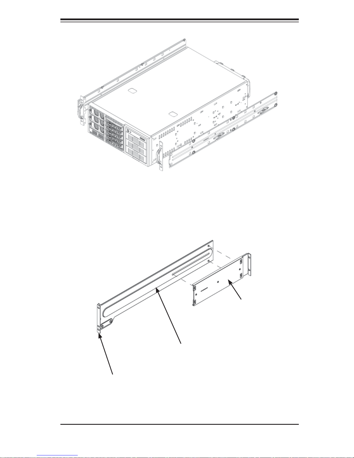
Chapter 2: Server Installation
Figure 2-1. Removing the Chassis Top Cover and Feet
Chassis Cover
Chassis Feet
Chassis Cover Lock
Identifying the Sections of the Rack Rails
The chassis package includes two rack rail assemblies in the rack mounting kit.
Each assembly consists of two sections: an inner fi xed chassis rail that secures
directly to the server chassis and an outer fi xed rack rail that secures directly to
the rack itself.
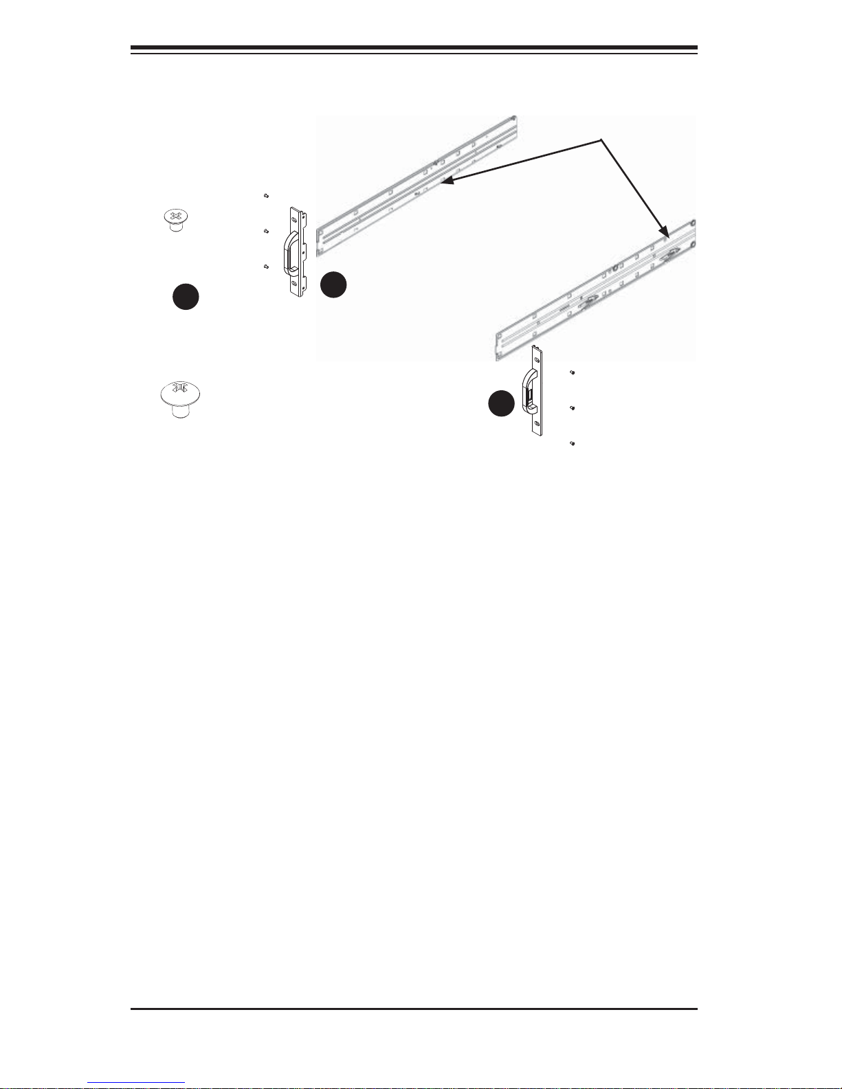
Installing the Chassis Handles and Inner Rails
Locate the chassis handles (2) and handle screws (6).1.
Align the chassis handle with the front of the chassis and secure with the 2.
three chassis handle screws.
Repeats steps 1 and 2 with the other handle.3.
2-5
Page 20
SUPERSERVER 8046B-6RF/8046B-TRF User's Manual
Figure 2-2. Identifying the Inner Rails and Chassis Handles
Chassis Handle
Screw
1
1
1
1
Inner Rails
1
1
Chassis Rail
Screw
Locate the inner rails (2) and screws (12) in the shipping package.4.
Align the inner rails against the chassis, as shown. Confi rm that the rails are 5.
fl ushed against the edge of the chassis.
Tighten the screws. Do not over tighten.6.
Repeat steps 5 and 6 with the other inner rail.7.
Installing the Outer Rails to the Rack
Attach the front and rear short brackets to the outside of the long bracket. 1.
Both bracket ends must face the same direction.
Chassis Handle
Adjust both the brackets to the proper distance so that the rail fi ts snugly into 2.
the rack.
Secure the front side of the outer rail with two M5 screws and the rear side 3.
of the outer rail with three M5 screws. Note: The outer rail is adjustable from
approximately 26" to 38.25".
Repeat steps 1-3 for the left outer rail.4.
2-6
Page 21
Chapter 2: Server Installation
Figure 2-3. Installing the Inner Rack Rails
Secure to the
Rear of the Rack
Attach to Rear
Bracket
Secure to the
Front of the Rack
Figure 2-4. Assembling the Outer Rails
2-7
Page 22
SUPERSERVER 8046B-6RF/8046B-TRF User's Manual
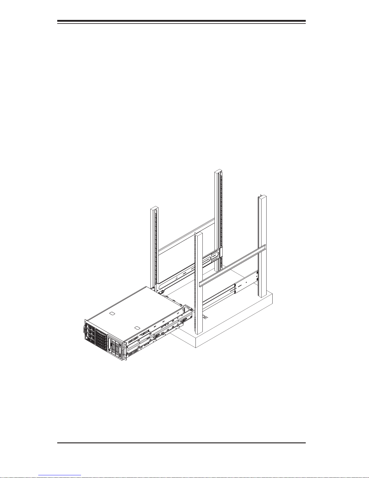
Installing the Chassis into a Rack
Confi rm that chassis includes the inner rails and the outer rails. 1.
Align the chassis rails with the front of the rack rails (C).2.
Slide the chassis rails into the rack rails, keeping the pressure even on both 3.
sides (you may have to depress the locking tabs when inserting). When the
server has been pushed completely into the rack, you should hear the locking
tabs "click".
Figure 2-5. Installing the Chassis into a Rack
2-8
Page 23

Chapter 2: Server Installation
2-5 Checking the Serverboard Setup
After setting up the the system, you may need to open the unit to make sure all the
connections have been made.
Accessing the Inside of the System (see Figure 2-5)
If rack mounted, fi rst release the retention screws that secure the unit to the 1.
rack.
Grasp the two handles on either side and pull the unit straight out until it 2.
locks (you will hear a "click").)
There are two screws that secure the cover to the chassis - remove these 3.
fi rst.
Using the indentations on the side cover (see Figure 2-5), push the cover to 4.
slide it off the chassis.
Lift the cover from the chassis to gain full access to the inside of the server.5.
Checking the Components and Setup
You may have four processors already installed into the serverboard. Each 1.
processor should have its own heatsink attached. See Chapter 5 for instructions on processor and heat sink installation.
Your server may have come with system memory already installed. Make 2.
sure all DIMMs are fully seated in their slots. For details on adding system
memory, refer to Chapter 5.
If desired, you can install add-on cards to the system. See Chapter 5 for 3.
details on installing PCI add-on cards.
Make sure all power and data cables are properly connected and not blocking 4.
the chassis airfl ow. See Chapter 5 for details on cable connections.
2-9
Page 24
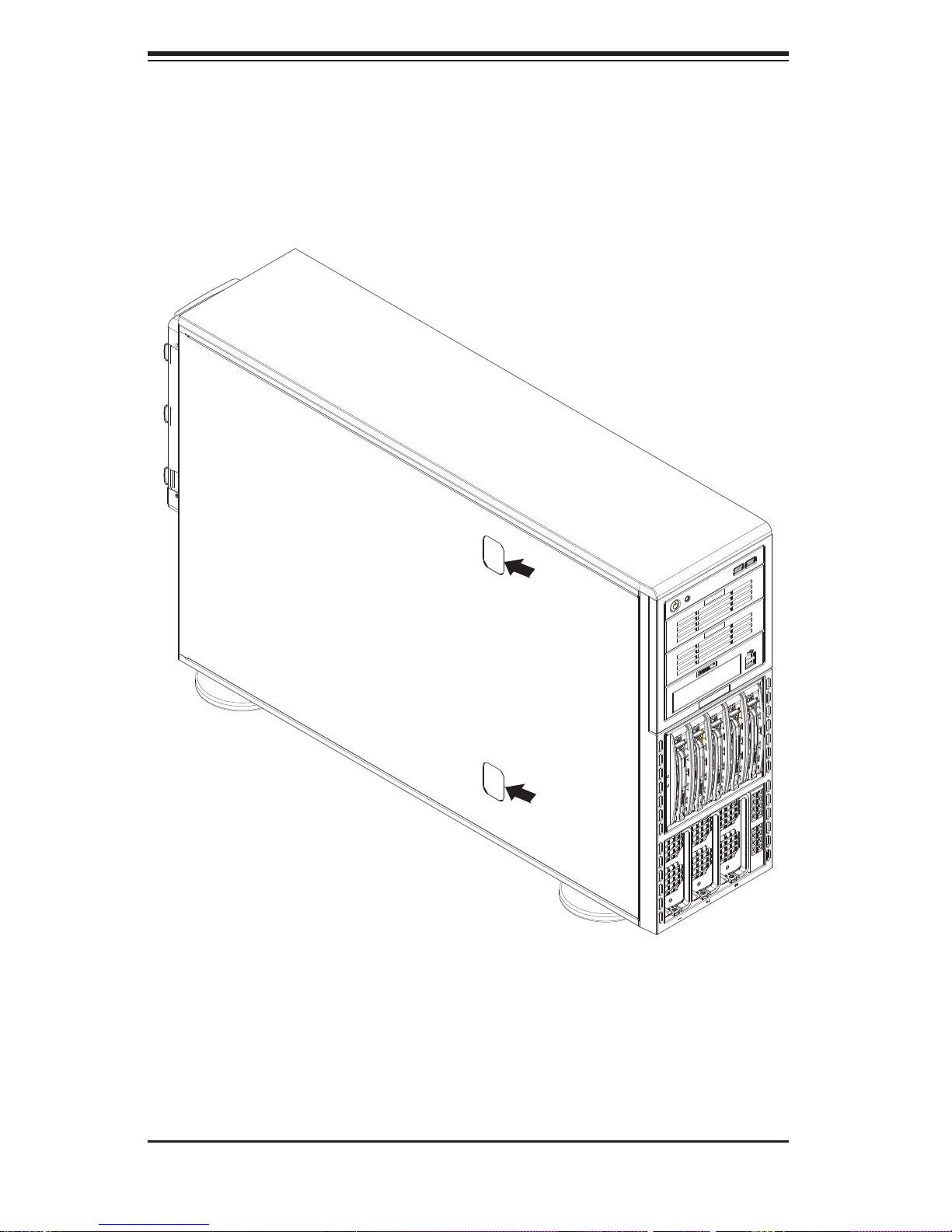
SUPERSERVER 8046B-6RF/8046B-TRF User's Manual
Figure 2-5. Accessing the Inside of the System
2-10
Page 25

Chapter 2: Server Installation
2-6 Preparing to Power On
Next, you should check to make sure the peripheral drives and the hard drives and
backplane have been properly installed and all connections have been made.
Checking the Drives
To install components into the 5.25" drive bays, you will need to remove the 1.
top/left chassis cover. Refer to Chapter 6 if you need to reinstall a DVD-ROM
and/or fl oppy disk drive to the system.
Depending upon your system's confi guration, your system may have one or 2.
more drives already installed. If you need to install hard drives, please refer
to Chapter 6.
Checking the Airfl ow
Airfl ow is provided by three 9-cm hot-swap chassis fans working in con-1.
junction with three 8-cm exhaust fans, which are located at the rear of the
chassis. The system component layout was carefully designed to promote
suffi cient airfl ow through the chassis.
Note that all power and data cables have been routed in such a way that they 2.
do not block the airfl ow generated by the fans. Keep this in mind when you
reroute them after working on the system.
Providing Power
Plug the AC power cords into a high-quality power strip that offers protection 1.
from electrical noise and power surges.
It is recommended that you use an uninterruptible power supply (UPS).2.
Finally, depress the power on button on the front of the chassis.3.
2-11
Page 26

SUPERSERVER 8046B-6RF/8046B-TRF User's Manual
Notes
2-12
Page 27
Chapter 3: System Interface
Chapter 3
System Interface
3-1 Overview
There are several LEDs on the control panel as well as others on the hard drive
carriers to keep you constantly informed of the overall status of the system as well
as the activity and health of specifi c components. There are also two buttons on
the chassis control panel and an on/off switch on the power supply. This chapter
explains the meanings of all LED indicators and the appropriate response you may
need to take.
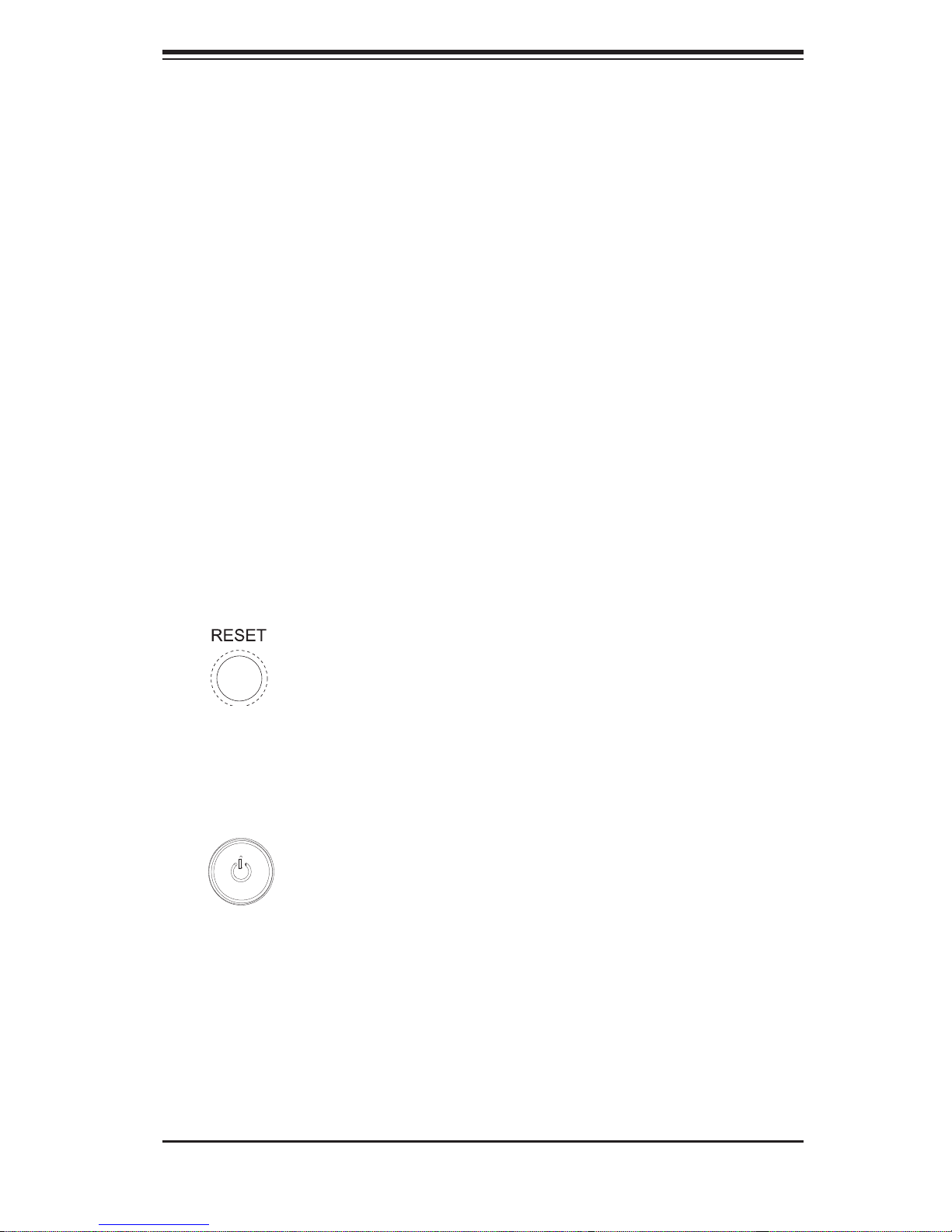
3-2 Control Panel Buttons
There are two push-buttons located on the front of the chassis: a reset button and
a power on/off button.
Reset
Use the reset button to reboot the system.
Power
The main power button is used to apply or remove power from the power supply
to the server system. Turning off system power with this button removes the main
power but keeps standby power supplied to the system.
3-1
Page 28
SUPERSERVER 8046B-6RF/8046B-TRF User's Manual
3-3 Control Panel LEDs
The control panel located on the front of the SC748TQ-R1400 chassis has fi ve
LEDs. These LEDs provide you with critical information related to different parts of
the system. This section explains what each LED indicates when illuminated and
any corrective action you may need to take.
Power Fail
Indicates a power supply module has failed. This should be accompanied by an
audible alarm. A backup power supply module will take the load and keep the
system running but the failed module will need to be replaced. Refer to Chapter 6
for details on replacing failed power supply modules. This LED should be off when
the system is operating normally.
Overheat/Fan Fail
When this LED fl ashes it indicates a fan failure. When on continuously (on and not
fl ashing) it indicates an overheat condition, which may be caused by cables ob-
structing the airfl ow in the system or the ambient room temperature being too warm.
Check the routing of the cables and make sure all fans are present and operating
normally. You should also check to make sure that the chassis covers are installed.
Finally , verify that the heatsinks are installed properly (see Chapter 5). This LED will
remain fl ashing or on as long as the overheat/fan fail condition exists.
2
NIC2
Indicates network activity on LAN2 when fl ashing .
3-2
Page 29

Chapter 3: System Interface
1
NIC1
Indicates network activity on LAN1 when fl ashing .
HDD
Indicates HDD activity. On the 8046B-6RF/8046B-TRF this light indicates HDD
and/or DVD - ROM dr ive acti vity w hen fl ashing.
Power
Indic ates power is bein g supplied to the sy stem's power supply u nits. This LED
should normally be illuminated when the system is operating.
3-3
Page 30

SUPERSERVER 8046B-6RF/8046B-TRF User's Manual
3-4 Hard Drive Carrier LEDs
Each drive carrier has two LEDs that function when a drive has been installed:
SAS Drives
Green:• When illuminated, the green LED on the drive carrier indicates the drive
is powere d on. When fl ashing it indicates data is being accessed on a drive.
If this LE D is not li t, it m eans n o power i s bein g prov ide d for t he dr ive. Please
refer to Chapter 6 for instructions on replacing failed drives.
Red:
• A solid red LED indicates a drive failure. If one of the drives fails, you
should be notifi ed by your system management software. Please refer to Chapter
6 for instructions on replacing failed drives. If this LED fl ashes ~ once per second
(1 Hz) it indicates RAID rebuilding activity.
SATA Drives
Green:• When fl ashing, the green LED on the drive carrier indicates drive activ-
ity. A conne ctio n to the bac kplane e nables t his LED to bli nk on and of f when
that particular drive is being accessed.
Red:
• The red LED to indicate a drive failure. If one of the drives fails, you should
be notifi ed by your system management software. Please refer to Chapter 6 for
instructions on replacing failed drives.
3-4
Page 31

Chapter 4: System Safety
!
Chapter 4
System Safety
4-1 Electrical Safety Precautions
Basic electrical safety precautions should be followed to protect yourself from harm
and the SuperServer 8046B-6RF/8046B-TRF from damage:
Be aware of the locations of the power on/off switch on the chassis as well
•
as the room's emergency power-off switch, disconnection switch or electrical
outlet. If an electrical accident occurs, you can then quickly remove power from
the system.
Do not work alone when working with high voltage components.
•
Power should always be disconnected from the system when removing or in-•
stalling main system components, such as the serverboard, memory modules
and fl oppy drive. When disconnecting power, you should fi rst power down the
system with the operating system fi rst and then unplug the power cords of all
the power supply units in the system.
When working around exposed electrical circuits, another person who is familiar
•
with the power-off controls should be nearby to switch off the power if necessary.
Use only one hand when working with powered-on electrical equipment. This
•
is to avoid making a complete circuit, which will cause electrical shock. Use
extreme caution when using metal tools, which can easily damage any electrical
components or circuit boards they come into contact with.
Do not use mats designed to decrease static electrical discharge as protection
•
from electrical shock. Instead, use rubber mats that have been specifi cally
designed as electrical insulators.
The power supply power cords must include a grounding plug and must be
•
plugged into grounded electrical outlets.
4-1
Page 32

SUPERSERVER 8046B-6RF/8046B-TRF User's Manual
!
Serverboard Battery: • CAUTION - There is a danger of explosion if the onboard
battery is installed upside down, which will reverse its polarites (see Figure 4-1).
This battery must be replaced only with the same or an equivalent type recommended by the manufacturer (CR2032). Dispose of used batteries according to
the manufacturer's instructions.
CD-ROM Laser:
• CAUTION - this server may have come equipped with a CD-
ROM drive. To prevent direct exposure to the laser beam and hazardous radiation exposure, do not open the enclosure or use the unit in any unconventional
way.
Mainboard replaceable soldered-in fuses: Self-resetting PTC (Positive Tempera-
•
ture Coeffi cient) fuses on the mainboard must be replaced by trained service
technicians only. The new fuse must be the same or equivalent as the one
replaced. Contact technical support for details and support.
4-2 General Safety Precautions
Follow these rules to ensure general safety:
Keep the area around the SuperServer 8046B-6RF/8046B-TRF clean and free
•
of clutter.
The SuperServer 8046B-6RF/8046B-TRF weighs approximately 65.5 lbs. (29.8
•
kg) when fully loaded. When lifting the system, two people at either end should
lift slowly with their feet spread out to distribute the weight. Always keep your
back straight and lift with your legs.
Place the chassis top cover and any system components that have been re-
•
moved away from the system or on a table so that they won't accidentally be
stepped on.
While working on the system, do not wear loose clothing such as neckties and
•
unbuttoned shirt sleeves, which can come into contact with electrical circuits or
be pulled into a cooling fan.
Remove any jewelry or metal objects from your body, which are excellent metal
•
conductors that can create short circuits and harm you if they come into contact
with printed circuit boards or areas where power is present.
4-2
Page 33

Chapter 4: System Safety
!
After accessing the inside of the system, close the system back up and secure •
it to the rack unit with the retention screws after ensuring that all connections
have been made.
4-3 ESD Precautions
Electrostatic Discharge (ESD) is generated by two objects with different electrical
charges coming into contact with each other. An electrical discharge is created to
neutralize this difference, which can damage electronic com ponents and printed
circuit boards. The following measures are generally suffi cient to neutralize this
difference before contact is made to protect your equipment from ESD:
Use a grounded wrist strap designed to prevent static discharge.
•
Keep all components and printed circuit boards (PCBs) in their antistatic bags •
until ready for use.
Touch a grounded metal object before removing the board from the antistatic
•
bag.
Do not let components or PCBs come into contact with your clothing, which may
•
retain a charge even if you are wearing a wrist strap.
Handle a board by its edges only; do not touch its components, peripheral chips,
•
memory modules or contacts.
When handling chips or modules, avoid touching their pins.
•
Put the serverboard and peripherals back into their antistatic bags when not •
in use.
For grounding purposes, make sure your computer chassis provides excellent
•
conductivity between the power supply, the case, the mounting fasteners and
the serverboard.
4-3
Page 34

SUPERSERVER 8046B-6RF/8046B-TRF User's Manual
!
!
4-4 Operating Precautions
Care must be taken to assure that the chassis cover is in place when the 8046B6RF/8046B-TRF is operating to assure proper cooling. Out of warranty damage to
the system can occur if this practice is not strictly followed.
Figure 4-1. Installing the Onboard Battery
LITHIUM BATTERY
BATTERY HOLDER
Please handle used batteries carefully. Do not damage the battery in any way; a
damaged battery may release hazardous materials into the environment. Do not
discard a used battery in the garbage or a public landfi ll. Please comply with the
regulations set up by your local hazardous waste management agency to dispose
of your used battery properly.
4-4
Page 35

Chapter 5: Advanced Serverboard Setup
Chapter 5
Advanced Serverboard Setup
This chapter covers the steps required to install the X8QB6-F/X8QBE-F serverboard
into the chassis, connect the data and power cables and install add-on cards. All
serverboard jumpers and connections are also described. A layout and quick reference chart are included in this chapter for your reference. Remember to completely
close the chassis when you have fi nished working with the serverboard to better
cool and protect the system.
5-1 Handling the Serverboard
Electrostatic Discharge (ESD) can damage electronic com ponents. To prevent damage to any printed circuit boards (PCBs), it is important to handle them very carefully
(see previous chapter). To prevent the serverboard from bending, keep one hand
under the center of the board to support it when handling. The following measures
are generally suffi cient to protect your equipment from electric static discharge.
Precautions
Use a grounded wrist strap designed to prevent Electrostatic Discharge •
(ESD).
Touch a grounded metal object before removing any board from its antistatic
•
bag.
Handle a board by its edges only; do not touch its components, peripheral chips,
•
memory modules or gold contacts.
When handling chips or modules, avoid touching their pins.
•
Put the serverboard, add-on cards and peripherals back into their antistatic •
bags when not in use.
For grounding purposes, make sure your computer chassis provides excellent
•
conductivity between the power supply, the case, the mounting fasteners and
the serverboard.
5-1
Page 36

SUPERSERVER 8046B-6RF/8046B-TRF User's Manual
Unpacking
The serverboard is shipped in antistatic packaging to avoid electrical static discharge. When unpacking the board, make sure the person handling it is static
protected.
5-2 Serverboard Installation
This section explains the fi rst step of physically mounting the X8QB6-F/X8QBE-F
into the SC748TQ-R1400BP chassis. Following the steps in the order given will
eliminate the most common problems encountered in such an installation. To remove
the serverboard, follow the procedure in reverse order.
Installing to the Chassis
Access the inside of the system by removing the screws from the back lip of 1.
the top cover of the chassis, then pull the cover off.
The X8QB6-F/X8QBE-F requires a chassis big enough to support a 16" x 2.
16.79" serverboard, such as Supermicro's SC748TQ-R1400BP.
Make sure that the I/O ports on the serverboard align properly with their 3.
respective holes in the I/O shield at the back of the chassis.
Carefully mount the serverboard to the serverboard tray by aligning the board 4.
holes with the raised metal standoffs that are visible in the chassis.
Insert screws into all the mounting holes on your serverboard that line up 5.
with the standoffs and tighten until snug (if you screw them in too tight, you
might strip the threads). Metal screws provide an electrical contact to the
serverboard ground to provide a continuous ground for the system.
Finish by replacing the top cover of the chassis.6.
5-2
Page 37

Chapter 5: Advanced Serverboard Setup
5-3 Connecting Cables
Now that the serverboard is installed, the next step is to connect the cables to the
board. These include the data (ribbon) cables for the peripherals and control panel
and the power cables.
Connecting Data Cables
The cables used to transfer data from the peripheral devices have been carefully
routed to prevent them from blocking the fl ow of cooling air that moves through
the system from front to back. If you need to disconnect any of these cables, you
should take care to keep them routed as they were originally after reconnecting
them (make sure of the pin 1 locations before connecting wires). The following data
cables (with their locations noted) should be connected. (See the layout on page
5-11 for connector locations.)
SAS drive data cables (SAS0 ~ SAS5, 8046B-6RF)
•
SATA drive cables (I-SATA0~5, 8046B-TRF)•
Control Panel cable (JF1)•
Important! Make sure the cables do not come into contact with the fans.
Connecting Power Cables
The X8QB6-F/X8QBE-F has a 24-pin primary power supply connector (JPW3) for
connection to the ATX power supply. In addition, there are three 8-pin secondary
power connectors (JPW1, JPW2, JPW4) that also must be connected to your power
supply. See Section 5-9 for power connector pin defi nitions.
Connecting the Control Panel
JF1 contains header pins for various front control panel connectors. See Figure 5-1
for the pin locations of the various front control panel buttons and LED indicators.
All JF1 wires have been bundled into a single ribbon cable to simplify this connection. Make sure the red wire plugs into pin 1 as marked on the board. The other
end connects to the Control Panel PCB board, located just behind the system status
LEDs on the chassis. See Section 5-9 for details and pin descriptions.
5-3
Page 38

SUPERSERVER 8046B-6RF/8046B-TRF User's Manual
1
2345678
Figure 5-1. Control Panel Header Pins
1920
Ground
NMI
X
FP PWRLED
HDD LED
NIC1 Link LED
NIC2 Link LED
Blue+ (OH/Fan Fail/
PWR FaiL/UID LED)
Power Fail LED
Ground
Ground
2
X
3.3 V
ID_UID_SW/3/3V Stby
NIC1 Activity LED
NIC2 Activity LED
Red+ (Blue LED Cathode)
3.3V
Reset
1
PWR
Reset Button
Power Button
5-4 I/O Ports
The system provides the I/O ports shown below at the rear of the chassis. There
are two additional USB ports located on the front of the chassis.
Figure 5-2. I/O Ports
Rear I/O Ports
1. COM1 Port 5. IPMI Dedicated LAN
2. VGA Port 1 6. LAN1 Port
3. USB0 Port 7. LAN2 Port
4. USB1 Port 8. UID Switch
5-4
Page 39

Chapter 5: Advanced Serverboard Setup
!
5-5 Installing the Processor and Heatsink
Avoid placing direct pressure to the top of the processor package. Always
remove the power cord fi rst before adding, removing or changing any
hardware components.
Notes: Always connect the power cord last and remove it before adding, removing or changing any components. Make sure to install the processor into the CPU
socket before you install the CPU heat sink. You will also need to fi rst remove the
air shroud (see Chapter 6). Be sure to replace the air shroud in its proper position
after installing the processors and heat sinks.
Intel's boxed Xeon CPU package contains the CPU fan and heatsink assembly. If
you buy the CPUs separately, use only Intel-certifi ed heatsinks and fans.
Inspect the CPU socket and make sure that the CPU plastic cap is in place and
none of the socket pins are bent. Otherwise, contact the retailer immediately.
For proper system setup, please follow the procedure below:
Press the socket clip to release 1.
the load plate, which covers the
CPU socket, from its locking
position.
Gently lift the socket clip to open 2.
the load plate.
Hold the plastic cap at its north 3.
and south center edges to remove it from the CPU socket.
Align the CPU key, which is 4.
a semi-circle cutout, with the
socket key, which is the notch
below the gold dot on the side of
the socket.
CPU Key
5-5
Page 40

SUPERSERVER 8046B-6RF/8046B-TRF User's Manual
!
Align pin 1 on the CPU with pin 1 5.
on the CPU socket.
Once both the CPU and the socket 6.
are aligned, carefully lower the
CPU straight down into the socket.
(To avoid damaging the CPU or
the socket, do not rub the CPU
against the surface of the socket
or its pins.)
With the CPU inside the socket, 7.
inspect the four corners of the
CPU to make sure that the CPU is
fl at and properly installed.
Once the CPU is securely seated 8.
on the socket, lower the CPU load
plate to the socket.
Use your thumb to gently push the 9.
socket clip down to the clip lock.
CPU Pin 1
Repeat to install any addiitonal 10.
processors.
Warning: Please save the plastic cap. The serverboard must be shipped
with the plastic cap properly installed to protect the CPU socket pins.
Shipment without the plastic cap properly installed will cause damage
to the socket pins.
Installing a Passive CPU Heatsink
Apply the proper amount of thermal grease (with thickness of up to 0.13 mm) 1.
to the heatsink.
Place the heatsink on top of the CPU so that the two retention screws on the 2.
heatsink are aligned with the standoff on the socket's backplate.
3. Secure the retention screws on each side with gentle and equal force. Gradually
work one s ide the n the other ; do not se cure on e side dow n all the way fi rst.
5-6
Page 41

Chapter 5: Advanced Serverboard Setup
!
Warning: We do not recommend removing the CPU or the heat sink.
However, if you do need to uninstall the heat sink, please follow these
instructions to avoid damaging the CPU or the CPU socket.
Removing the Passive Heatsink
Power off the system and unplug the power cord from the power supply.1.
Release the heat sink screw gently and equally on both sides. Do not com-2.
pletely release one side before the loosening the other.
Hold the heatsink as shown in the picture below and 3. gently wriggle the
heatsink to loosen it from the CPU (do not use excessive force).
Once the heatsink is loose, remove the heatsink from the motherboard.4.
To reinstall the CPU and the heatsink, clean the surface of the CPU and the 5.
heatsink to get rid of the old thermal grease. Reapply the proper amount of
thermal grease to the CPU surface before reinstalling the heatsink on the
motherboard.
5-7
Page 42

SUPERSERVER 8046B-6RF/8046B-TRF User's Manual
!
5-6 Installing Memory
CAUTION! Exercise extreme care when installing or removing DIMM
modules to prevent any possible damage.
Memory Support
The X8QB6-F/X8QBE-F can support up to 512 GB of registered ECC DDR31333/1066/800 memory. (DDR-1333 memory will run at 1066 MHz.) Memory modules of the same size and speed should be used within the same bank. You will
also need to fi rst remove the air shroud (see Chapter 6). Be sure to replace the air
shroud in its proper position after installing memory.
Installing Memory Modules
Insert the desired number of DIMMs into the memory slots, starting with 1.
P1-DIMM #1A. To enhance memory performance, install pairs of memory
modules of the same type and speed, beginning with DIMM #1A and DIMM
#2A, then DIMM #1B and DIMM #2B (see confi guration table below).
Position the key on the bottom of the DIMM so that it aligns with the receptive 2.
point on the slot.
Use both thumbs together to press the notches on both ends of the module 3.
straight down into the slot until the module snaps into place.
Press the release tabs to the lock positions to secure the DIMM module into 4.
the slot.
Notches
Release
Press Down
Lock/Release Tabs
Release
5-8
Page 43

Chapter 5: Advanced Serverboard Setup
Confi guring Memory
Follow th e table s below f or co rrec t memo ry c onfi guration.
Processors and their Corresponding Memory Modules
CPU# Corresponding DIMM Slots
CPU 1 P1-1A P1-2A P1-3A P1-4A P1-5A P1-6A P1-7A P1-8A
CPU2 P2-1A P2-2A P2-3A P2-4A P2-5A P2-6A P2-7A P2-8A
CPU3 P3-1A P3-2A P3-3A P3-4A P3-5A P3-6A P3-7A P3-8A
CPU4 P4-1A P4-2A P4-3A P4-4A P4-5A P4-6A P4-7A P4-8A
Processor and Memory Module Population
Number of
CPUs+DIMMs
1 CPU &
2 DIMMs
1 CPU &
4 DIMMs
1 CPU &
5~8 DIMMs
2 CPUs &
4 DIMMs
CPU1
P1-1A/P1-3A
CPU1
P1-1A/P1-3A, P1-5A/P1-7A
CPU1
P1-1A/P1-3A, P1-5A/P1-7A + Any memory pairs in P1-2A/-4A/-6A/-8A DIMM slots
CPU1 + CPU2
P1-1A/P1-3A, P2-1A/P2-3A
CPU and Memory Population Confi guration Table
(For memory to work properly, please install DIMMs in pairs)
2 CPUs &
6 DIMMs
2 CPUs &
8 DIMMs
2 CPUs &
10~16 DIMMs
3 CPUs &
6 DIMMs
3 CPUs &
8 DIMMs
3 CPUs &
10 DIMMs
4 CPUs &
12 DIMMs
CPU1 + CPU2
P1-1A/P1-3A/P1-5A/P1-7A, P2-1A/P2-3A
CPU1 + CPU2
P1-1A/P1-3A/P1-5A/P1-7A, P2-1A/P2-3A/P2-5A/P2-7A
CPU1/CPU2
P1-1A/P1-3A/P1-5A/P1-7A, P2-1A/P2-3A/P2-5A/P2-7A + Any memory pairs in P1, P2
DIMM slots
CPU1/CPU2 + CPU3 or CPU4
P1-1A/P1-3A, P2-1A/P2-3A + P3-1A/P3-3A (if CPU 3 is installed)
P1-1A/P1-3A, P2-1A/P2-3A + P4-1A/P4-3A (if CPU 4 is installed)
CPU1/CPU2 + CPU3 or CPU4
P1-1A/P1-3A/P1-5A/P1-7A, P2-1A/P2-3A + P3-1A/P3-3A (if CPU 3 is installed)
P1-1A/P1-3A/P1-5A/P1-7A, P2-1A/P2-3A + P4-1A/P4-3A (if CPU 4 is installed)
CPU1/CPU2 + CPU3 or CPU4
P1-1A/P1-3A/P1-5A/P1-7A, P2-1A/P2-3A/P2-5A/P2-7A + P3-1A/P3-3A (if CPU 3 is
installed)
P1-1A/P1-3A/P1-5A/P1-7A, P2-1A/P2-3A/P2-5A/P2-7A + P4-1A/P4-3A (if CPU 4 is
installed)
CPU1/CPU2 + CPU3 or CPU4
P1-1A/P1-3A/P1-5A/P1-7A, P2-1A/P2-3A/P2-5A/P2-7A + P3-1A/P3-3A/ P3-5A/P3-7A
(if CPU 3 is installed)
P1-1A/P1-3A/P1-5A/P1-7A, P2-1A/P2-3A/P2-5A/P2-7A + P4-1A/P4-3A/ P4-5A/P43-7A
(if CPU 4 is installed)
5-9
Page 44

SUPERSERVER 8046B-6RF/8046B-TRF User's Manual
5-7 Adding PCI Add-On Cards
The 8046B-6RF/8046B-TRF has four PCI slots for add-on cards.
Installing an Add-on Card
Begin by removing the PCI slot shield for the slot you wish to populate.1.
Fully seat the card into the riser card slot, pushing down with your thumbs 2.
evenly on both sides of the card.
Finish by using a screw to secure the top of the card shield to the chassis. 3.
The PCI slot shields protect the serverboard and its components from EMI
and aid in proper ventilation, so make sure there is always a shield covering
each unused slot.
5-10
Page 45

5-8 Serverboard Details
5
Figure 5-5. X8QB6-F/X8QBE-F Layout
(not drawn to scale)
FAN10
JUIDB1
SP1
P1-DIMM1A
LAN1
(LOWER)
LAN2
(UPPER)
USB2/3
COM2
I-SATA0
I-SATA2
I-SATA4
JP6
JPWR5
JPWR4
JPRST1
JWOR
IPMB
BMCRST
J40
JP4
U101
JD1
JWD1
JLPC1
JP10
PORT80
1
J35
Intel ICH 10R
USB5
FAN 11
I-SATA1
I-SATA3
I-SATA5
J59
JP5
JL1
JPI2C1
D10
BMC CTRL
Slot1 PCI-E 2.0 X8
JPB1
JBT1
Intel
IOH 7500
BBU
BMC_HB
Winbond
Intel 82576
LAN CTRL
JPS1
Slot2 PCI-E 2.0 X16/X8
U70
BIOS
JPT1
JPG1
JUID_OW1
LSI 2108
SAS CTRL
JPWR1JPWR2
Slot3 PCI-E 2.0 X8
JP3
JP1
SAS0~3
Slot4 PCI-E 2.0 X16/X8
SAS4~7
JPWR3
UID_SWITCH
JPL1
P1-DIMM4A
UID_LED
P1-DIMM3A
LED26
P1-DIMM2A
CPU1
Chapter 5: Advanced Serverboard Setup
USB0/1
IPMI_LAN
P1-DIMM5A
P1-DIMM6A
CPU2
VGA
P1-DIMM7A
P1-DIMM8A
COM1
P3-DIMM4A
P3-DIMM3A
P3-DIMM1A
P3-DIMM2A
CPU3
FAN9
X8QBE-F
Rev. 1.11
FAN8
P3-DIMM6A
P3-DIMM5A
CPU4
P3-DIMM8A
P3-DIMM7A
P5V_STBY
LED5
LED6
FAN7
LED7
LED8
LED9
P2-DIMM7A
P2-DIMM8A
P2-DIMM6A
P2-DIMM5A
FAN6
BT2
Battery
5-11
FAN4
FAN
P2-DIMM2A
P2-DIMM1A
P2-DIMM4A
P2-DIMM3A
P4-DIMM8A
P4-DIMM7A
P4-DIMM6A
P4-DIMM5A
FAN3
JF1
OHLED
JOH1
FAN1
P4-DIMM1A
FAN2
P4-DIMM3A
P4-DIMM2A
P4-DIMM4A
Page 46

SUPERSERVER 8046B-6RF/8046B-TRF User's Manual
X8QB6-F/X8QBE-F Quick Reference
Jumper Description Default Setting
JBT1 Clear CMOS See Section 5-9
JPG1 VGA Enable Pins 1-2 (Enabled)
JPL1 LAN1/LAN2 Enable Pins 1-2 (Enabled)
JPS1 (X8QB6-F only) SAS2 Enable Pins 1-2 (Enabled)
JPT1 TPM Enable Pins 1-2 (Enabled)
JWD1 Watch Dog Pins 1-2 (Reset)
Connector Description
COM1 COM1 Serial Connection
FAN 1~10 Fan Headers
IPMB 4-pin External BMC I
I-SATA 0~5 Intel SB SATA Connectors 0~5
BBU Connector for LSI SAS Battery Backup Unit (X8QB6-F only)
2
C Header (for an IPMI Card)
JD1 Speaker/Power LED Indicator
JF1 Front Panel Control Header
JL1 Chassis Intrusion Header
JLPC1 TPM/Port 80 Header
JOH1 Overheat/Fan Fail LED Header
2
JPI
C Power Supply SMBbus I2C Header
JPW1~2, JPW4~5 12V 8-Pin Power Connectors
JPW3 ATX 24-Pin Power Connector
JUID_OW1 UID Override Header
LAN1/LAN2 Gb Ethernet Ports 1/2
(IPMI) LAN IPMI_Dedicated LAN
SAS 0~3, 4~7 Serial Attached SCSI Connectors 0~3, 4~7
TPM/Port 80 Trusted Platform Module/Port 80 Header
T-SGPIO 1/2 Serial_Link General Purpose I/O Headers
USB 0/1/2/3/5 Back Panel (USB 0/1) and Front Access (USB2/3, 5)
UID Switch Universal Identifi er Switch
LED Description
D10 BMC Heartbeat LED
LED8 St andby PW R LED
LED26 UID LED
5-12
Page 47

Chapter 5: Advanced Serverboard Setup
5-9 Connector Defi nitions
Main ATX Power Supply
Connector
The primary power supply connector (JPW3) meets the SSI EPS 12V
specifi cation. Refer to the table on
the right for the pin defi nitions of the
ATX 24-pin power connector. You
must also connect the 8-pin (JPW1/
JPW2/JPW4/JPW5) processor power
connectors to your power supply (see
below).
Processor Power Connector
The power supply must be connected
to any three of the JPW1, JPW2 and
JPW4 and JPW5 power headers.
See the table on the right for pin
defi nitions.
ATX Power 24-pin Connector
Pin Defi nitions
Pin# Defi nition Pin # Defi nition
13 +3.3V 1 +3.3V
14 -12V 2 +3.3V
15 COM 3 COM
16 PS_ON 4 +5V
17 COM 5 COM
18 COM 6 +5V
19 COM 7 COM
20 Res (NC) 8 PWR_OK
21 +5V 9 5VSB
22 +5V 10 +12V
23 +5V 11 +12V
24 COM 12 +3.3V
+12V 8-pin Power
Pin Defi nitions
Pins Defi nition
1 - 4 Ground
5 - 8 +12V
Required Connection
PW_ON Connector
The PW_ON connector is on pins 1
and 2 of JF1. This header should be
connected to the chassis power button. See the table on the right for pin
defi nitions.
Reset Connector
The reset connector is located on pins
3 and 4 of JF1 and attaches to the
reset switch on the computer chassis. See the table on the right for pin
defi nitions.
Power Fail LED
The Power Fail LED connection is located on pins 5 and 6 of JF 1. See the
table o n the ri ght for p in defi nitions.
Power Button
Pin Defi nitions (JF1)
Pin# Defi nition
1 PW_ON
2 Ground
Reset Button
Pin Defi nitions (JF1)
Pin# Defi nition
3 Reset
4 Ground
PWR Fail LED
Pin Defi nitions (JF1)
Pin# Defi nition
5 3.3V
6 PWR Supply Fail
5-13
Page 48

SUPERSERVER 8046B-6RF/8046B-TRF User's Manual
Overheat (OH)/Fan Fail/PWR Fail/
UID LED
Conne ct an LED c able to pi ns 7 and
8 of JF1 to use the Overheat/Fan Fail/
Power Fail and UID LED connections.
The red LE D on p in 7 p r ovi d es wa r n ings of over heat , fan f ailur e or po wer
failure. Ref er to t he t ab le on t he r i ght
for pin de fi nitions.
NIC2 (JLAN2) LED
The LED connections for JLAN2 are
on pins 9 and 10 of JF1. Attach an
LED cable to display network activity. See the table on the right for pin
defi nitions.
OH/Fan Fail/UID LED Pin Defi nitions
(JF1)
Pin# Defi nition
7 Vcc/Front UID LED
8 OH/Fan Fail LED
OH/Fan Fail LED Status
(Red LED)
State Defi nition
Off Normal
On Overheat
Flashing Fan Fail
NIC2 LED
Pin Defi nitions (JF1)
Pin# Defi nition
9 Vcc
10 Ground
NIC1 (JLAN1) LED
The LED connections for JLAN1 are
on pins 11 and 12 of JF1. Attach an
LED cable to display network activity. See the table on the right for pin
defi nitions.
HDD LED
The HDD LED connection is located
on pins 13 and 14 of JF1. This LED
is used to display all HDD activity. See the table on the right for pin
defi nitions.
NIC1 LED
Pin Defi nitions (JF1)
Pin# Defi nition
11 Vcc
12 Ground
HDD LED
Pin Defi nitions (JF1)
Pin# Defi nition
13 Vcc
14 HDD Active
5-14
Page 49

Chapter 5: Advanced Serverboard Setup
Power On LED
The Power On LED connector is located on pins 15 and 16 of JF1 (use
JLED for a 3-pin connector). This
connection is used to provide LED
indication of power being supplied to
the system. See the table on the right
for pin defi nitions.
NMI Button
The non-maskable interrupt button
header is located on pins 19 and 20
of JF1. Refer to the table on the right
for pin defi nitions.
Fan Headers
Power LED
Pin Defi nitions (JF1)
Pin# Defi nition
15 5V Stby
16 Control
NMI Button
Pin Defi nitions (JF1)
Pin# Defi nition
19 Control
20 Ground
There are 10 fan headers on the
serverboard, all of which are 4-pin
fans (pins 1-3 of the fan headers
are backward compatible with the
tradit ional 3- pin fans). See the tab le
on the right for pin defi nitions. The
onboard fan speeds are controlled b y
Thermal Management (via Hardware
Monitoring) under the Advanced Section in the BIOS (with 4-pin fans only).
The default is Full Speed.
Chassis Intrusion
A Chassis Intrusion header is located
at JL1 on the motherboard. Attach an
appropriate cable from the chassis to
inform you of a chassis intrusion when
the chassis is opened.
Fan Header
Pin Defi nitions
Pin# Defi nition
1 Ground (Black)
2 +12V (Red)
3 Tachometer
4 PWM Control
Chassis Intrusion
Pin Defi nitions
Pin# Defi nition
1 Intrusion Input
2 Ground
5-15
Page 50

SUPERSERVER 8046B-6RF/8046B-TRF User's Manual
TPM Header/Port 80
A Trusted Platform Module/Port 80
header is located at LPCI to provide
TPM support and Port 80 connection
performance and security enhancement. See the table on the right for
pin defi nitions.
Overheat LED/Fan Fail
The JOH1 header is used to connect
an LED indi cat or to p rovi de war ni ngs
of chass is overheat ing or fan fa ilure.
This LED w ill b link w he n a fan f ailu re
occu rs. Ref er to t he t abl e on r ight f or
pin defi nitions.
TPM/Port 80 Header
Pin Defi nitions
Pin # Defi nition Pin # Defi nition
1 LCLK 2 GND
3 LFRAME# 4 <(KEY)>
5 LRESET# 6 +5V (X)
7 LAD 3 8 LAD 2
9 +3.3V 10 LAD1
11 LAD0 12 GND
13 SMB_CLK4 14 SMB_DAT4
15 +3V_DUAL 16 SERIRQ
17 GND 18 CLKRUN# (X)
19 LPCPD# 20 LDRQ# (X)
Overheat LED
Pin Defi nitions
Pin# Defi nition
1 Vcc
2 OH/Fan Fail LED
OH/Fan Fail LED
Status
State Message
Solid Overheat
Blinking Fan Fail
T-SGPIO 1/2 Headers
Two SGPIO (Serial-Link General
Purpose Input/Output) headers are
included to support Serial_Link interfaces for onboard SATA connections.
See the table on the right for pin
defi nitions.
Gb Ethernet Ports
Two gigabit Ethernet ports (LAN1 and
LAN2) are located on the I/O backplane. A dedicated IPMI LAN is also
included above the two USB ports.
These ports accept RJ45 type cables.
T-SGPIO
Pin Defi nitions
Pin# Defi nition Pin Defi nition
1NC 2 NC
3 Ground 4 Data
5 Load 6 Ground
7 Clock 8 NC
No Connection
5-16
Page 51

Chapter 5: Advanced Serverboard Setup
Serial Ports
A serial port is included on the
serverboard backpanel. See the table
on the right for pin defi nitions.
Universal Serial Bus (USB)
Two Universal Serial Bus ports (USB
0/1) are located on the I/O backpanel.
Additional onboard USB headers
(USB 2/3, USB5) can provide front
chassis access. See the tables on the
right for pin defi nitions.
Serial Port Pin Defi nitions
Pin # Defi nition Pin # Defi nition
1 DCD 6 DSR
2 RXD 7 RTS
3 TXD 8 CTS
4 DTR 9 RI
5 Ground 10 NC
USB0/1
Pin Defi nitions
Pin# Defi nition
1 +5V
2 PO3 PO+
4 Ground
5NA
USB2
Pin # Defi nition
1 +5V 1 +5V
2 PO- 2 PO3 PO+ 3 PO+
4 Ground 4 Ground
5 NC 5 Key
(NC= No connection)
USB2/3, USB5
Pin Defi nitions
USB3/5
Pin # Defi nition
Internal Speaker
The Internal Speaker (SP1) provides
audible indications for various beep
codes. See the table on the right for
pin defi nitions.
Power LED/Speaker
On the JD1 header, pins 1-3 are used
for power LED indication and pins 4-7
are for the speaker. See the tables
on the right for pin defi nitions. Please
note that the speaker connector pins
(4-7) are for use with an external
speaker. If you wish to use the onboard speaker, you should close pins
6-7 with a jumper.
Internal Buzzer (SP1)
Pin Defi nition
Pin# Defi nitions
Pin 1 Pos. (+) Beep In
Pin 2 Neg. (-) Alarm
Speaker
PWR LED Connector
Pin Defi nitions
Pin Setting Defi nition
Pin 1 Anode (+)
Pin2 Cathode (-)
Pin3 NA
Speaker Connector
Pin Settings
Pin Setting Defi nition
Pins 4-7 External Speaker
Pins 6-7 Internal Speaker
5-17
Page 52

SUPERSERVER 8046B-6RF/8046B-TRF User's Manual
Unit Identifi er Switch
A Unit Identifi er (UID) switch LED Indi-
cators are included on the serverboard.
The UID switch is located next to the
LAN ports on the backplane. The UID
LED (LED26) is located next to the
UID switch. When you press the UID
switch, the UID LED indicators will turn
on. Press the UID switch again to turn
it off. These UID indicators provide
easy identifi cation of a system unit that
may be in need of service.
Color/State OS Status
Note: UID can also be triggered via
IPMI. For more information on IPMI,
please refer to the IPMI User's Guide
posted on our Website @http://www.
supermicro.com.
Blue: On Windows OS Unit Identifi ed
Blue:
Blinking
UID Switch
Pin# Defi nition
1 Ground
2 Ground
3 Button In
4 Ground
UID LED
Status
Linux OS Unit Identifi ed
Power SMB (I2C) Connector
The Power System Management Bus
2
(I
C) connector (JPI2C) monitors power
supply, fan and system temperatures.
See the table on the right for pin
defi nitions.
IPMB
A System Management Bus header for
IPMI 2.0 is designated IPMB. Connect
the appropriate cable here to use the
2
IPMB I
C connection on your system.
PWR SMB
Pin Defi nitions
Pin# Defi nition
1 Clock
2 Data
3 PWR Fail
4 Ground
5 +3.3V
IPMB Header
Pin Defi nitions
Pin# Defi nition
1 Data
2 Ground
3 Clock
4 No Connection
5-18
Page 53

5-10 Jumper Settings
Explanation of Jumpers
To modify the operation of the
serverboard, jumpers can be used
to choose between optional settings.
Jumpers create shorts between two
pins to change the function of the con-
nector. Pin 1 is identifi ed with a square
solder pad on the printed circuit board.
See the serverboard layout pages for
jumper locations.
Note: On a two-pin jumper, "Closed"
means the jumper is on both pins and
"Open" means the jumper is either on
only one pin or completely removed.
Chapter 5: Advanced Serverboard Setup
3 2 1
Connector
Pins
Jumper
3 2 1
Setting
CMOS Clear
JBT1 is used to clear CMOS (which will also clear any passwords). Instead of pins,
this jumper consists of contact pads to prevent accidentally clearing the contents
of CMOS.
To clear CMOS,
First power down the system and unplug the power cord(s).1.
With the power disconnected, short the CMOS pads with a metal object such 2.
as a small screwdriver.
Remove the screwdriver (or shorting device).3.
Reconnect the power cord(s) and power on the system.4.
Note: Do not use the PW_ON connector to clear CMOS.
5-19
Page 54

SUPERSERVER 8046B-6RF/8046B-TRF User's Manual
LAN1/2 Enable/Disable
Change the setting of jumper JPL1 to
enable or disable the LAN1/LAN2 Ethernets port on the serverboard. See the
table on the right for jumper settings.
The default setting is enabled.
LAN1/2 Enable/Disable
Jumper Settings
Jumper Setting Defi nition
Pins 1-2 Enabled
Pins 2-3 Disabled
VGA Enable/Disable
JPG1 allows you to enable or disable
the VGA port. The default position is on
pins 1 and 2 to enable VGA. See the
table on the right for jumper settings.
TPM Support Enable
JPT1 allows the user to enable TPM
(Trusted Platform Modules) support
to enhance data integrity and system
security. See the table on the right for
jumper settings. The default setting is
enabled.
SAS2 Enable (X8QB6-F only)
Close pins 1-2 to enable SAS2 (Serial
Attached SCSI) support for the X8QB6F serverboard. See the table on the
right for jumper settings. The default
setting is enabled.
VGA Enable/Disable
Jumper Settings
Jumper Setting Defi nition
Pins 1-2 Enabled
Pins 2-3 Disabled
TPM Support Enable/Disbale
Jumper Settings
Jumper Setting Defi nition
1-2 Enabled
2-3 Disabled
SAS2 Enable/Disable
Jumper Settings
Jumper Setting Defi nition
1-2 Enabled (Default)
2-3 Disabled
Watch Dog Enable/Disable
JWD controls the Watch Dog function.
Watch Dog is a system monitor that
can reboot the system when a software
application hangs. Jumping pins 1-2
will cause WD to reset the system if an
application hangs. Jumping pins 2-3
will generate a non-maskable interrupt
signal for the application that hangs.
See the table on the right for jumper
settings. Watch Dog must also be enabled in BIOS.
Watch Dog
Jumper Settings
Jumper Setting Defi nition
Pins 1-2 Reset
Pins 2-3 NMI
Open Disabled
5-20
Page 55

5-11 Onboard Indicators
Chapter 5: Advanced Serverboard Setup
LAN1/2 LEDs
The Ethernet ports have two LEDs. On
each port, one LED indicates activity
while the other LED may be green,
amber or off to indicate the speed of
the connection. See the table on the
right for the functions associated with
the connection speed LED.
IPMI Dedicated LAN LEDs
A dedicated IPMI LAN is also lo-
cated on the I/O backplane of the
serverboard. The amber LED on the
right indicates activity, while the green
LED on the le f t in dic a tes t he sp ee d of
the co nnecti on. See th e table at r ight
for more in format ion.
(Connection Speed Indicator)
LAN1/2 LED
LED Color Defi nition
Off NC or 10 Mb/s
Green 100 Mb/s
Amber 1 Gb/s
IPMI LAN (F models only)
Link LED Activity LED
IPMI LAN Link LED (Left) &
Activity LED (Right)
Color/State Defi nition
Link (Left) Green: Solid 100 Mb/s
Activity (Right) Amber: Blinking Active
Onboard Power LED
An Onb oard Power LED is lo cated at
LED8 on the serverboard. When this
LED is lit, the system is on. Be sure
to turn of f the sys tem and unpl ug the
power cord before removing or install-
ing components. See the table at right
for more in format ion.
BMC Heartbeat LED
A BMC Heartbeat LED is located at
D10 on the ser verboard. When D10
is blinking, BMC functions normally.
See the table at right for more infor-
mation.
Onboard PWR LED (LED8)
LED Color Defi nition
Off System Off (PWR cable
Green System On
Green:
Flashing
Quickly
Green:
Flashing
Slowly
not connected)
ACPI S1 State
ACPI S3 (STR) State
BMC Heartbeat LED
Status
Color/State Defi nition
Green:
Blinking
BMC: Normal
5-21
Page 56

SUPERSERVER 8046B-6RF/8046B-TRF User's Manual
5-12 SAS and SATA Ports
SAS Ports
Eight SAS ports are supported
on the serverboard. See the
table on the right for pin defi ni-
tions. Please note that SAS
ports are included with the
8046B-6RF system only.
Pin # Defi nition
1 Ground
2 TXP
3 TXN
4 Ground
5 RXN
6 RXP
7 Ground
SAS Port
Pin Defi nitions
SATA Ports
There are no jumpers to confi gure the six onboard SATA
ports. See the table on the right
for pin defi nitions.
SATA Port
Pin Defi nitions
Pin # Defi nition
1 Ground
2 TXP
3 TXN
4 Ground
5 RXN
6 RXP
7 Ground
5-22
Page 57

Chapter 6: Advanced Chassis Setup
Chapter 6
Advanced Chassis Setup
This chapter covers the steps required to install components and perform mainte-
nance on the SC748TQ-R1400BP chassis. For component installation, follow the
steps in the order given to eliminate the most common problems encountered. If
some steps are unnecessary, skip ahead to the step that follows.
Tools Required: The only tool you will need to install components and perform
maintenance is a Philips screwdriver.
6-1 Static-Sensitive Devices
Electrostatic Discharge (ESD) can damage electronic com ponents. To prevent
damage to any printed circuit boards (PCBs), it is important to handle them very
carefully. The following measures are generally suffi cient to protect your equipment
from ESD damage.
Precautions
Use a grounded wrist strap designed to prevent static discharge.•
Touch a grounded metal object before removing any board from its antistatic •
bag.
Handle a board by its edges only; do not touch its components, peripheral chips,
•
memory modules or gold contacts.
When handling chips or modules, avoid touching their pins.
•
Put the motherboard, add-on cards and peripherals back into their antistatic •
bags when not in use.
For grounding purposes, make sure your computer chassis provides excellent
•
conductivity between the power supply, the case, the mounting fasteners and
the serverboard.
6-1
Page 58

SUPERSERVER 8046B-6RF/8046B-TRF User's Manual
Unpacking
When unpacking the system, make sure the person handling it is static protected.
Figure 6-1. System Front View
5.25" Drive Bays (3)
System ResetMain Power
System LEDs
USB Ports
Hard Drive Bays (5)
2x Power Supply
Modules (module on
the right is a dummy)
6-2
Page 59

Chapter 6: Advanced Chassis Setup
6-2 Control Panel
The front control panel must be connected to the JF1 connector on the serverboard
to provide you with system status and alarm indications. A ribbon cable has bundled
these wires together to simplify this connection.
Connect the cable from JF1 on the serverboard (making sure the red wire plugs
into pin 1) to the appropriate connector on the front control panel PCB. Pull all ex-
cess cabling over to the control panel side of the chassis. The LEDs on the control
panel inform you of system status - see Figure 6-2 for details. See Chapter 5 for
details on JF1.
Power
HDD
NIC1
NIC2
Overheat/
Fan Fail
Figure 6-2. Front Control Panel LEDs
Indicates power is being supplied to the system.
Indicates IDE device and hard drive activity. On the
SC748TQ-R1400BP, this LED indicates SAS or SATA drive
activity when fl ashing.
1
Indicates network activity on LAN port 1.
2
Indicates network activity on LAN port 2
When this LED fl ashes, it indicates a fan failure. When on
continuously it indicates an overheat condition (see Chapter
3 for details).
Power Fail
Indicates a power supply failure.
6-3
Page 60

SUPERSERVER 8046B-6RF/8046B-TRF User's Manual
6-3 System Fans
Three 9-cm chassis cooling fans (located in the center of the chassis) provide
cooling airfl ow while three 8-cm exhaust fans expel hot air from the chassis. The
fans should all be connected to headers on the serverboard (see Chapter 5). Each
power supply module also has a cooling fan.
Fan Failure
Under normal operation all chassis fans, exhaust fans and the power supply fans
run continuously. If the system LED indicates a fan failure, you should determine
which fan has failed and replace it. The system fans are hot-swappable and can
be replaced without powering down the system.
Replacing System Fans
Removing a Fan
First locate the failed fan by removing the top/left chassis cover (see Chapter 1.
2 for details). Locate the fan that has stopped working.
Depress the locking tabs on the failed chassis fan. On an exhaust fan, push 2.
down on the colored tab then pull the unit straight out. The wiring for these
fans has been designed to detach automatically.
Installing a New Fan
Replace the failed fan with an identical one (available from Supermicro)1.
Install it in the same position and orientation as the one you removed. A 2.
"click" can be heard when the fan is fully installed.
Check that the fan is working then replace the top/left side chassis panel.3.
Removing/Installing the Air Shroud
Note: Under most circumstances you won't need to remove the air shroud to perform
service on the system and it should remain in place when the system is running
Depress the tabs at the front and rear of the shroud to unlock it.1.
Lift it up and out of the chassis (see Figure 6-4). To reinstall, simply position 2.
the air shroud in its proper place and push it in until you hear it click.
6-4
Page 61

Chapter 6: Advanced Chassis Setup
Figure 6-3. Removing Chassis Fans
Figure 6-4. Removing the Air Shroud
6-5
Page 62

SUPERSERVER 8046B-6RF/8046B-TRF User's Manual
6-4 Drive Bay Installation
Hard Drives
The hard drives are mounted in drive carriers to simplify their installation and
removal from the chassis. These carriers also help promote proper airfl ow for the
drives. For this reason, even empty carriers without hard drives installed must
remain in the chassis. A total of fi ve SAS or SATA drives may be housed in the
SC748TQ-R1400BP chassis. The drive IDs are preconfi gured as 0 through 4 in
order from right to left (or from bottom to top if rackmounted).
Installing/Removing Hot-swap Hard Drives
The hard drive carriers are all easily accessible at the front of the chassis. These
drives are hot-swappable, meaning they can be removed and installed without
powering down the system.
Push the release button on the carrier located beside the drive LEDs.1.
Swing the handle fully out and then use it to pull the drive straight out.2.
Note: Your operating system must have RAID support to enable the hot-swap
capability of the hard drives.
Mounting a Hard Drive in a Drive Carrier
The hard drive carriers help to promote proper airfl ow for the system. For this reason,
even carriers without hard drives must remain in the server.
Insert the drive into the carrier with the printed circuit board side facing down 1.
so that the mounting holes align with those in the carrier.
Secure the drive to the carrier with four screws (see Figure 6-5).2.
SAS/SATA Backplane
The hard drives plug into a SAS/SATA backplane on the CSE-M35P mobile rack,
which houses the hard drive bays. The drive data cables must be connected from
the serverboard to the appropriate connectors on the backplane. There are also two
power connectors on the backplane - both should be connected.
6-6
Page 63

Chapter 6: Advanced Chassis Setup
!
!
!
Figure 6-4. Removing a Hard Drive Carrier
Figure 6-5. Mounting a Hard Drive in a Carrier
Regardless of how many hard drives are installed, all drive carriers must
remain in the drive bays to promote proper airfl ow.
Enterprise level hard disk drives are recommended for use in Supermicro
chassis and servers. For information on recommended HDDs, visit the
Supermicro Web site at http://www.supermicro.com/products/nfo/storage.
cfm
Important! Use extreme caution when working around the SAS/SA TA backplane. Do not touch the backplane with any metal objects and make sure
no ribbon cables touch the backplane or obstruct the airfl ow holes.
6-7
Page 64

SUPERSERVER 8046B-6RF/8046B-TRF User's Manual
Installing Components in the 5.25" Drive Bays
The 8046B-6RF/8046B-TRF has three empty 5.25" drive bays. A fl oppy drive, hard
drives or DVD/CD-ROM drives can be installed into these 5.25" drive bays.
Removing the Empty Drive Bay
First power down the system.1.
Remove the top/left chassis cover to access the drive components.2.
With the cover off, remove the screws that secure the drive carrier to the 3.
chassis (one side only) then push the entire empty drive carrier out from the
back.
Adding a DVD/CD-ROM Drive
Remove the guide plates (one on each side) from the empty drive carrier 1.
and screw them into both sides of the DVD/CD-ROM drive using the holes
provided.
Slide the DVD/CD-ROM into the bay and secure it to the chassis with the 2.
drive carrier screws you fi rst removed.
Attach the power and data cables to the drive.3.
Replace the top/left chassis cover and restore power to the system.4.
Adding an HDD or Floppy Drive
Install an HDD or fl oppy into one of the removed empty drive carriers 1. with the
printed circuit board side toward the carrier so that the drive's mounting holes
align with those in the carrier.
Secure the drive to the carrier with screws then slide the assembly into 2.
the bay and secure it to the chassis with the drive carrier screws you fi rst
removed.
Attach the power and data cables to the drive.3.
Replace the top/left chassis cover and restore power to the system.4.
Note: A red wire typically designates the location of pin 1. Drive carriers should
remain in any empty drive bays to maintain proper airfl ow within the chassis.
6-8
Page 65

Hard Drive
Chapter 6: Advanced Chassis Setup
Figure 6-7. Adding a Component in a 5.25" Drive Bay
Hard Drive Tray
6-5 Power Supply
The SuperServer 8046B-6RF/8046B-TRF has a redundant 1400 watt power supply
consisting of two power modules. (A third may be added for triple redundancy.) Each
power module has an auto-switching capability, which enables it to automatically
sense and operate at a 100V - 240V input voltage.
Power Supply Failure
If either of the two power supply modules fail, the other module will take the full
load and allow the system to continue operation without interruption. The PWR Fail
LED will illuminate and remain on until the failed unit has been replaced. Replace-
ment units can be ordered directly from Supermicro. The hot-swap capability of the
power supply modules allows you to replace the failed module without powering
down the system.
Removing/Replacing the Power Supply
You do not need to shut down the system to replace a power supply unit. The
redundant feature will keep the system up and running while you replace the failed
hot-swap module. Replace with the same model (see Appendix B).
6-9
Page 66

SUPERSERVER 8046B-6RF/8046B-TRF User's Manual
Removing the Power Supply
First unplug the AC power cord that corresponds to the failed power supply 1.
unit. The power cords are oriented the same as the modules are (the left/top
power cord corresponds to the left/top power module).
Depress the locking tab on the power supply unit and pull the unit straight out 2.
by the handle. See Figure 6-8.
Installing a New Power Supply
Replace the failed module with another power supply module. It must be the 1.
exact same. Refer to Appendix B for the correct part number.
Push the new power supply unit into the power bay until you hear a click.2.
Plug the AC power cord back in. 3.
Figure 6-8. Removing a Power Supply Module
6-10
Page 67

Chapter 7: BIOS
Chapter 7
BIOS
7-1 Introduction
This chapter describes the AMI BIOS Setup Utility for the X8QB6-F/X8QBE-F. The
AMI ROM BIOS is stored in a Flash EEPROM and can be easily updated. This chap-
ter describes the basic navigation of the AMI BIOS Setup Utility setup screens.
Starting BIOS Setup Utility
To enter the AMI BIOS Setup Utility screens, press the <Delete> key while the
system is booting up.
Note: In most cases, the <Delete> key is used to invoke the AMI BIOS
setup screen. There are a few cases when other keys are used, such as
<F1>, <F2>, etc.
Each main BIOS menu option is described in this manual. The Main BIOS setup
menu screen has two main frames. The left frame displays all the options that can
be confi gured. Grayed-out options cannot be confi gured. Options in blue can be
confi gured by the user. The right frame displays the key legend. Above the key
legend is an area reserved for a text message. When an option is selected in the
left frame, it is highlighted in white. Often a text message will accompany it. (Note:
the AMI BIOS has default text messages built in. Supermicro retains the option to
include, omit, or change any of these text messages.)
The AMI BIOS Setup Utility uses a key-based navigation system called "hot keys."
Most of the AMI BIOS setup utility "hot keys" can be used at any time during the
setup navigation process. These keys include <F1>, <F10>, <Enter>, <ESC>, ar-
row keys, etc.
Note: Options printed in Bold are default settings.
How To Change the Confi guration Data
The confi guration data that determines the system parameters may be changed by
entering the AMI BIOS Setup utility. This Setup utility can be accessed by pressing
<Del> at the appropriate time during system boot.
Note: For AMI BIOS Recovery, please refer to the AMI BIOS Recovery
Instructions posted on our website at http://www.supermicro.com/support/
manuals/.
7-1
Page 68

SUPERSERVER 8046B-6RF/8046B-TRF User's Manual
Starting the Setup Utility
Normally, the only visible Power-On Self-Test (POST) routine is the memory test.
As the memory is being tested, press the <Delete> key to enter the main menu of
the AMI BIOS Setup Utility. From the main menu, you can access the other setup
screens. An AMI BIOS identifi cation string is displayed at the left bottom corner of
the screen below the copyright message.
Warning! Do not upgrade the BIOS unless your system has a BIOS-related
issue. Flashing the wrong BIOS can cause irreparable damage to the
system. In no event shall Supermicro be liable for direct, indirect, special,
incidental, or consequential damages arising from a BIOS update. If you
have to update the BIOS, do not shut down or reset the system while the
BIOS is updating to avoid possible boot failure.
7-2 Main Setup
When you fi rst enter the AMI BIOS Setup Utility , you will enter the Main setup screen.
You can always return to the Main setup screen by selecting the Main tab on the
top of the screen. The Main BIOS Setup screen is shown below.
7-2
Page 69

Chapter 7: BIOS
System Overview: The following BIOS information will be displayed:
System Time/System Date
Use this option to change the system time and date. Highlight System Time or Sys-
tem Date using the arrow keys. Enter new values through the keyboard and press
<Enter>. Press the <Tab> key to move between fi elds. The date must be entered in
Day MM/DD/YY format. The time is entered in HH:MM:SS format. (Note: The time
is in the 24-hour format. For example, 5:30 P.M. appears as 17:30:00.)
Supermicro X8QB6/E
BIOS Version
• : This item displays the BIOS vision used in your system.
BIOS Build Date
• : This item displays the date when this BIOS was built.
Processor
The AMI BIOS will automatically display the status of the processor used in your
system:
CPU Type
• : This item displays the type of CPU used in the motherboard.
Speed
• : This item displays the CPU speed as detected by the BIOS.
Physical Count
• : This item displays the number of processors installed in your
system as detected by the BIOS.
Logical Count
• : This item displays the number of CPU Cores detected in your
system by the BIOS.
System Memory
Size
• : This displays the size of memory available in the system.
7-3
Page 70

SUPERSERVER 8046B-6RF/8046B-TRF User's Manual
7-3 Advanced Setup Confi gurations
Use the arrow keys to select Boot Setup and press <Enter> to access the submenu
items.
Warning: Be sure to select the correct setting for each item in this section.
A wrong setting selected may cause the system to malfunction.
XBoot Features
Quick Boot
If enabled, this feature will skip certain tests during POST to reduce the time needed
for system boot. The options are Enabled and Disabled.
Quiet Boot
Use this feature to modify the bootup screen display between POST messages
or the OEM logo. Select Disabled to display the POST messages. Select Enabled
to display the OEM logo instead of the normal POST messages. The options are
Enabled and Disabled.
AddOn ROM Display Mode
This feature sets the display mode for the Option ROM. The options are Force
BIOS and Keep Current.
Bootup Num-Lock
This feature is used to select the Power-on state for the Numlock key. The options
are Of f and On.
7-4
Page 71

Chapter 7: BIOS
PS/2 Mouse Support
Select Enabled to enable PS/2 Mouse support. Select Auto to enable the onboard
PS/2 mo use w hen a PS /2 m ouse i s detec ted. T he o ptio ns ar e Enabl e, Dis abl ed,
and Aut o.
Wait For 'F1' If Error
This for ces t he syste m to wait unti l the ' F1' key is pressed wh en an er ror o ccu rs.
The opti ons are D isab led and Enab led.
Hit 'Del' Message Display
Select Enabled to display "Press DEL to run Setup" during POST. The options
are Enabled and Disabled.
Interrupt 19 Capture
Interrupt 19 is the software interrupt that handles boot disk functions. When this item
is set to Enabled, the ROM BIOS of the host adaptors will "capture" Interrupt 19
at bootup and allow the drives that are attached to these host adaptors to function
as bootable disks. If this item is set to Disabled, the ROM BIOS of the host adap-
tors will not capture Interrupt 19, and the drives attached to these adaptors will not
function as bootable devices. The options are Enabled and Disabled.
Watch Dog Function
If enable d, the Watch Dog Ti mer will allow the system to rebo ot when it is inac tive
for more t han 5 minu tes. The o ption s are Enabl ed and Disabled.
XProcessor and Clock Options
This submenu displays the status of the processor used in the motherboard and
allows the user to confi gure the Processor and Clock settings.
Spread Spectrum Mode
Select Enable to enable Clock Spectrum modulation support, which will allow the
BIOS to monitor and attempt to reduce the level of Electromagnetic Interference
caused by the components whenever needed. The options are Disabled and
Enabled.
Ratio CMOS Setting (Available when CPU Ratio is set to manual)
This option allows the user to set the ratio between the CPU Core Clock and the FSB
Frequency. (Note: if an invalid ratio is entered, the AMI BIOS will restore the setting
to the previous state.) The default setting depends on the type of CPU installed on
the motherboard. The default setting for this motherboard is [20].
7-5
Page 72

SUPERSERVER 8046B-6RF/8046B-TRF User's Manual
Sever Class
Use this item to identify the server class for your system so that the prefectcher
settings listed below can be correctly confi gured. The options are Enterprise, HPC
(High Performance Cluster) and Custom (for customized servers).
Hardware Prefetcher (Available when supported by the CPU)
If enabled, the hardware prefetcher will prefetch streams of data and instructions
from the main memory to the L2 cache to improve CPU performance. The options
are Disabled and Enabled.
Adjacent Cache Line Prefetch (Available when supported by the CPU)
If this feature is set to Disabled, the CPU prefetches the cache line for 64 bytes. If
this feature is set to Enabled, the CPU prefetches both cache lines for 128 bytes
as comprised.
MPS and ACPI MADT Ordering
This feature allows the user to confi gure the MPS (Multi-Processor Specifi ca-
tions) and ACPI settings for your motherboard. Select Modern Ordering if XP
or a newer version of Windows OS is used in the motherboard. Select Legacy
Order i ng i f 2000 or a n ea r li er ve r si on i s us ed. T he o pt io ns a re Modern Ordering
and Legacy Ordering.
Max CPUID Value Limit
This feature allows the user to set the maximum CPU ID value. Enable this feature
to boot the legacy operating systems that cannot support processors with extended
CPUID functions. The options are Enabled and Disabled (for the Windows OS).
Intel® Virtualization Technology (Available when supported by the CPU)
Select Enabled to enable Virtualization Tec hnolo gy suppor t whic h will all ow one
platf orm to r un mult iple op erati ng system s and app licat ions i n indep endent p ar titions, creating multiple "virtual" systems in one physical computer. The options are
Enabled and Dis able d. Note: If there i s any chan ge to thi s set ting, yo u will n eed
to power of f and re star t the syst em for the c hange to t ake eff ect. Pl ease refe r to
Intel’s web site for det ailed i nform ation.
Execute-Disable Bit Capability (Available when supported by the OS and
the CPU)
Select Enabled to enable the Execute Disable Bit support which will allow the processor to designate areas in the system memory where an application code can
execute and where it cannot, thus preventing a worm or a virus from fl ooding illegal
codes to overwhelm the processor or damage the system during an attack. The
default is Enabled. (Refer to Intel and Microsoft websites for more information.)
7-6
Page 73

Chapter 7: BIOS
CPU Multi-Core Enable/Disable (Available when supported by the CPU)
Select Enabled to enable multi-core CPU support to enhance CPU performance for
the following CPU Cores. The options are Disabled and Enabled.
Core 0/Core 1/Core 2/Core 3/Core 4/Core 5/Core 6/Core 7
•
A20M
When the A20M# pin is enabled, it will force address bit 20 to zero (to be masked)
to emulate the address wraparound for the real-address mode at 1 MB. Set this
item to Enabled for the legacy operating systems and applications that require A20M
support to work properly. The options are Enabled and Disabled.
Intel® SpeedStep™ Technology
Intel EIST (Enhanced Intel SpeedStep Technology) allows the system to automati-
cally adjust the processor voltage and core frequency in an effort to reduce power
consumption and heat dissipation. Please refer to Intel’s web site for detailed infor-
mation. The options are Disable (Disable GV3) and Enable (Enable GV3).
Intel® TurboMode Tech (Available when Intel EIST Technology is enabled)
Select Enabled to use the TurboMode Technique to boost system performance. The
options are Enabled and Disabled.
Performance/Walt Select
Use this feature to balance the need between system performance and energy sav-
ing. The options are Traditional and Power Optimized (for energy saving).
Intel® C-STATE Tech
If enabled, C-State is set by the system automatically to either C2, C3 or C4 state.
The options are Disabled and Enabled. If this feature is set to Enabled, the follow-
ing items will display.
C-State Package Limit Setting
If this feature is set to Auto, the AMI BIOS will automatically set the limit on the
C-State package register. The options are Auto, C1, C3, C6 and C7.
C1 Auto Demotion
Select Enabled to allow the CPU to demote C3, C6 or C7 requests to C1 based on
un-core auto-demote information. The options are Disabled and Enabled.
C3 Auto Demotion
If this feature is set to Enabled, the CPU will conditionally demote C6 or C7 re-
quests to C3 based on un-core auto-demote information. The options are Disabled
and Enabled.
7-7
Page 74

SUPERSERVER 8046B-6RF/8046B-TRF User's Manual
ACPI T State
When this feature is enabled, CPU Throttling state will be reported in the ACPI
(Advanced Confi guration and Power Interface) protocol. The options are Enabled
and Disabled.
XAdvanced Chipset Control
The items included in the Advanced Settings submenu are listed below.
XCPU Bridge Confi guration
XQPI Confi guration
QuickPath Interconnect (QPI) is the connection between the CPU and the motherboard's I/O hub. This section displays the following QPI items.
MMConfi gBase
This item is used to select the space-based address for memory_mapped con-
fi guration. The options are 0x8000 0000, 0x4000 0000, and 0xC000 0000.
MMIOH Size Per IOH
Use this feature to select the memory_mapped IOH size to be allocated to each
IOH. The options are 2G, 4G, 6G, and 8G.
Logical Interrupt Mode
This item is used to select the logical interrupt mode. The options are Flat Mode
and Cluster Mode.
Cluster Mode Check Sampling
Select Enabled to check if the APICID in an IntPriUpd message is not zero. The
options are Enabled and Disabled.
QPI Debug Message Output Level
This feature allows the user to decide the level of an QPI debug message to
be sent to the user. The options are Err/Warn/Info0/1, Err/Warn/Info0, and Err/
Warn.
CRC Mode
Use this feature to select the QPI CRC (Cyclic Redundancy Check) mode, which
will determine how often the raw computer data stored in a network or a hard disk
device is checked for CRC. The options are 8Bit CRC and 16Bit Rolling CRC.
7-8
Page 75

Chapter 7: BIOS
QPI (Quick Path Interconnect) Links Speed
Use this feature to set data transfer speed for QPI Link connections. The options
are Slow and Fast.
QPI Frequency Select (Available if the item - QPI Link Speed is set to
Fast)
This feature is used to set desired QPI frequency. The options are 4.800 GT,
5.866GT, 6.400 GT and Auto.
QPI Scrambling
Select Enabled to enable Bit-Shuffl ing support which will allow bits in the data
fl ow to be shifted around for CRC checking during data transmission and receiv-
ing between the CPUs or between a CPU and an IO hub (IOH). The options are
Enabled and Disabled.
XIntegrated Memory Controller Confi guration
Interleave Type
Use this feature to select memory interleaving mode. Select Inter-Socket Block
Interleaving to enable memory interleaving between blocks of memory modules
installed in different DIMM slots. Select Intra-Socket Block Interleaving to enable
memory interleaving between blocks of memory modules installed in the same
DIMM slot. Select Automatic to allow BIOS to automatically select the memory
interleaving mode for memory modules installed in the system. The options are
No Interleaving, Inter-Socket Block Interleaving, Intra-Socket Block Interleaving, and Automatic.
Interleave Order
Use this feature to set the order of memory interleaving. The options are High
Only, High Low, Low High 0, and Low High 1.
Mirroring
Mirroring support allows data stored in one location to be copied into another
location for data redundancy and security. The options are listed below:
No Mirroring
• (Mirroring Disabled),
Intra-Socket Mirrored Nx1 to Nx3 (Memory Controller 1 to Memory Controller 3
•
of the same DIMM socket),
Intra-Socket Mirrored Nx3 to Nx1 (Memory Controller 3 to Memory Controller 1
•
of the same DIMM socket),
7-9
Page 76

SUPERSERVER 8046B-6RF/8046B-TRF User's Manual
Inter-Socket Mirrored S0 (Socket 0) to S1 (Socket 1), and S2 (Socket 2) to •
S3 (Socket 3),
Inter-Socket Mirrored S0 (Socket 0) to S2 (Socket 2) and S1 (Socket 1) to S3
•
(Socket 3),
Inter-Socket Mirrored S0 (Socket 0) to S3 (Socket 3) and S1 (Socket 1) to S2
•
(Socket 2).
Spare Enable
Select Enabled to enable spare support for all sockets, creating a spare drive
for each socket. The options are Enabled and Disabled.
Mapper Mode
Use this feature to set the memory_mapper mode. The memory_maper is used
to translate local physical addresses presented by a media device into DRAM
memory addresses (in terms of rank, bank, row and column). Select Open to
maximize open_page hits. Select Close to minimize rank confl icts and to maxi-
mize command and simultaneous read/write bandwidth to boost performance.
Select Adaptive to spread power dissipation over different DIMM modules to
avoid memory overheating. The options are Close, Open and Adaptive.
Frequency Limit
This feature forces a DDR3 memory module to run at a frequency other than
what the system has detected. The available options are Auto, 800 MHz, 978
MHz, 1067 MHz, and Auto.
Initialization Mode
Use this feature to select the memory initialization mode. The options are Serial
and Parallel.
Hemisphere Mode
This feature is used to set the memory hemisphere mode. Select Enabled to
prevent CPU's cache agent 1 from accessing cache agent 2 in an effort to
reduce memory latency and maximize performance. This setting requires that
both DIMM modules and DRAM sizes are confi gured in the same way. Select
Disabled to allow a CPU's cache agent 1 to access cache agent 2. The options
are Disabled and Enabled.
Page Policy
Use this feature to confi gure Page_Policy settings. A page is a set of memory
blocks cached in a DRAM buffer that determines sub-commands needed for a
memory module to access a particular page. Select Open to optimize memory
7-10
Page 77

Chapter 7: BIOS
performance. Select Close to use memory safe mode. Select Adaptive to balance
safety and performance. The options are Close, Open and Adaptive.
Scheduler Policy
Use this feature to confi gure Scheduler_Policy settings. The scheduler is used
to translate memory read/write commands into memory sub-commands for easy
execution. Select Static Trade Off to balance read/write priority. Select Static
Read Priority to optimize read latency and bandwidth. Select Static Write Priority
to optimize write bandwidth to expedite command writing and execution. Select
Adaptive to minimize latency. The options are Static Trade Off, Static Read
Priority, Static Write Priority, and Adaptive.
ECC Check Time Interval
This feature is used to set the time interval between each ECC Memory checking.
If an ECC error occurs, an error message will also be sent via IPMI. The options
are 100 Msec, 1 Sec, 10 Sec, 1 Min, 5 Minutes, and 10 Minutes.
XNorth Bridge Confi guration
This feature allows the user to confi gure the settings for the North Bridge set-
tings.
Relaxed Ordering
Select Enabled to enable PCI Express Relaxed Ordering support which will allow
certain transactions to violate the strict PCI-E ordering rules and be carried out
fi rst by passing other transactions that were issued earlier. The options are Auto,
Disabled and Enabled.
Maximum Payload Size
This feature is used to set the maximum payload size for a PCI-Express device.
Please refer to your add-on card user guide for the desired setting. The options
are Auto, 128 Bytes, 256 Bytes, 512 Bytes, 1024 Bytes, 2048 Bytes, 4096 Bytes,
and Maximum supported.
Extended Tag Field
Select Enabled to use the 8-bit Tag fi eld of a device as a requester. The options
are Auto, Disabled and Enabled.
No Snoop
If this feature is set to Enabled, No_Snoop option for a PCI-Express device will be
enabled. The options are Auto, Disabled and Enabled.
7-11
Page 78

SUPERSERVER 8046B-6RF/8046B-TRF User's Manual
Maximum Read Request Size
This feature is used to set the maximum read request size for a PCI-Express device.
The options are Auto, 128 Bytes, 256 Bytes, 512 Bytes, 1024 Bytes, 2048 Bytes,
4096 Bytes, and Maximum supported.
Active State Power Management
Select Enabled to use the power management for signal transactions between the
PCI Express L0 and L1 Links. Select Enabled to confi gure PCI-Exp. L0 and L1 Link
power states. The options are Disabled and Enabled.
Extended Synch
Select Enabled to generate extended synchronization patterns. The options are
Auto, Disabled and Enabled.
Intel VT-d
Select Enabled to enable Intel Virtualization Technology support for Direct I/O VT-d
by reporting the I/O device assignments to VMM through the DMAR ACPI Tables.
This feature offers fully-protected I/O resource-sharing across the Intel platforms,
providing the user with greater reliability, security and availability in networking and
data-sharing. The settings are Enabled and Disabled.
Thermal Sensor
Select Enabled to activate the thermal sensor. The options are Disabled and
Enabled.
XSouth Bridge Confi guration
This feature allows the user to confi gure Intel ICH South Bridge settings.
USB Functions
This feature allows the user to decide the number of onboard USB ports to be enabled. The Options are: Disabled, 2 USB Ports,4 USB Ports, 6 USB Ports, 8 USB
Ports, 10 USB Ports, and 12 USB Ports. (If this item is set to Enabled, USB 2.0
Controller will be enabled.)
USB Port Confi guration
This feature is used to confi gure USB port settings. The Options are: 6x6 USB
Ports and 8x4 USB Ports.
USB 2.0 Controller
Select Enabled to activate the USB 2.0 Controller. The options are Enabled and
Disabled. (Note: If the item - USB Functions is enabled, USB 2.0 Controller will
7-12
Page 79

Chapter 7: BIOS
always be enabled. When the item - USB Functions is set to Disabled, the user has
the option to enable or disable USB 2.0 Controller.)
HDA Controller
Select Enabled to enable the High-Defi nition Audio Controller. The settings are
Enabled and Disabled.
SMBUS Controller
Select Enabled to enable the System_Management Bus Controller. The settings
are Enabled and Disabled.
SLP_S4# Min. Assertion Width
This feature allows the user to set the minimum SLP_S4# Assertion Width to ensure
that the DRAMs have safe power cycles. The settings are 4 to 5 seconds, 3 to 4
Seconds, 2 to 3 Seconds, and 1 to 2 Seconds.
Restore on AC Power Loss
Use this feature to set the power state after a power outage. Select Power-Off for
the system power to remain off after a power outage. Select Power-On for the
system power to be turned on after a power outage. Select Last State to allow the
system to resume its last state before the power outage. The options are Power-On,
Power-Off and Last State.
SATA Master Break Event
If this feature is set to Enabled, activities on the SATA master drive will break from
the C3/C6 state. The settings are Enabled and Disabled.
PCIE Ports Confi guration
PCIE Port 0 ~ PCIE Port 4
This feature is used to confi gure PCI-E port settings. Select Auto to allow a speci-
fi ed PCIE port to be enabled if a PCIE device is detected. The settings are Auto,
Enabled and Disabled.
PCIE High Priority Port
This feature allows the user to select the PCIE High Priority port. The settings are
Disabled, Port 0, Port 1, Port 2, Port 3, Port 4, and Port 5.
PCIE Port 0 IOxAPIC Enable ~ PCIE Port 4 IOxAPIC Enable
Select Enable to enable IOxAPIC support for a PCIE port specifi ed. The settings
are Enabled and Disabled.
7-13
Page 80

SUPERSERVER 8046B-6RF/8046B-TRF User's Manual
XIDE/SATA Confi guration
When this submenu is selected, the AMI BIOS will automatically detect the presence
of the IDE/SATA devices, and displays the following items.
SATA#1 Confi guration
If Compatible is selected, it sets SATA#1 to the legacy_compatible mode. Selecting Enhanced sets SATA#1 to the native SATA mode. The options are Disabled,
Compatible and Enhanced.
Confi gure SATA#1 as (Not available when SATA#1 Confi guration is
disabled)
Use this feature to select the drive type for SATA#1. The options are IDE, RAID
and AHCI. (When the option-RAID is selected, the item-ICH RAID Code Base
will appear. When the option-AHCI is selected, the item-ICH AHCI Codebase
will be available.)
ICH RAID Code Base (Available when the option-RAID is selected.)
Select Intel to use Intel's SA T A RAID fi rmware to confi gure Intel's SA T A RAID
settings. Select Adaptec to use Adaptec's SATA RAID fi rmware to confi gure
Adaptec's SATA RAID settings. The options are Intel and Adaptec.
ICH AHCI Codebase (Available when the option-AHCI is selected.)
Use this feature to select the AHCI Codebase for the ICH South Bridge. The
options are BIOS Native Module and Intel AHCI ROM.
SATA#2 Confi guration (Available when the option-IDE is selected.)
Select Enhanced to set SATA#2 to the native SATA mode. The options are
Disabled and Enhanced.
Primary IDE Master/Slave, Secondary IDE Master/Slave, Third IDE Master,
and Fourth IDE Master
These settings allow the user to set the parameters the slots indicated above.
Press <Enter> to activate the following submenu screen for details. Set the correct
confi gurations accordingly. The items included in the submenu are listed below.
Type
Use this item to select the type of device connected to the system. The options
are Not Installed, Auto, CD/DVD and ARMD.
LBA/Large Mode
LBA (Logical Block Addressing) is a method of addressing data on a disk drive.
In the LBA mode, the maximum drive capacity is 137 GB. For drive capacities
over 137 GB, your system must support a 48-bit LBA mode addressing. If not,
7-14
Page 81

Chapter 7: BIOS
contact your manufacturer or install an ATA/133 IDE controller card that supports
48-bit LBA mode. The options are Disabled and Auto.
Block (Multi-Sector Transfer)
Block Mode boosts the IDE drive performance by increasing the amount of data
transferred. Only 512 bytes of data can be transferred per interrupt if Block Mode
is not used. Block Mode supports transfers of up to 64 KB per interrupt. Select
Disabled to allow data to be transferred from and to the device one sector at a
time. Select Auto to allow data transfer from and to the device multiple sectors
at a time if the device supports it. The options are Auto and Disabled.
PIO Mode
The IDE PIO (Programmable I/O) Mode programs timing cycles between the
IDE drive and the programmable IDE controller. As the PIO mode increases, the
cycle time decreases. The options are Auto, 0, 1, 2, 3, and 4.
Select Auto to allow the AMI BIOS to automatically detect the PIO mode. Use
this value if the IDE disk drive support cannot be determined.
Select 0 to allow the AMI BIOS to use PIO mode 0. It has a data transfer rate
of 3.3 MB/s.
Select 1 to allow the AMI BIOS to use PIO mode 1. It has a data transfer rate
of 5.2 MB/s.
Select 2 to allow the AMI BIOS to use PIO mode 2. It has a data transfer rate
of 8.3 MB/s.
Select 3 to allow the AMI BIOS to use PIO mode 3. It has a data transfer rate
of 11.1 MB/s.
Select 4 to allow the AMI BIOS to use PIO mode 4. It has a data transfer bandwidth of 32-Bits. Select Enabled to enable 32-Bit data transfer.
Select UDMA5 to allow the BIOS to use Ultra DMA mode 5. It has a data transfer
rate of 133 MB/s.
Select UDMA6 to allow the BIOS to use Ultra DMA mode 6. It has a data transfer
rate of 133 MB/s. The options are Auto, SWDMAn, MWDMAn, and UDMAn.
DMA Mode
Select Auto to allow BIOS to automatically detect IDE DMA mode when IDE disk
drive support cannot be determined.
Select SWDMA0 to allow BIOS to use Single Word DMA mode 0. It has a data
transfer rate of 2.1 MB/s.
Select SWDMA1 to allow BIOS to use Single Word DMA mode 1. It has a data
transfer rate of 4.2 MB/s.
7-15
Page 82

SUPERSERVER 8046B-6RF/8046B-TRF User's Manual
Select SWDMA2 to allow BIOS to use Single Word DMA mode 2. It has a data
transfer rate of 8.3 MB/s.
Select MWDMA0 to allow BIOS to use Multi-Word DMA mode 0. It has a data
transfer rate of 4.2 MB/s.
Select MWDMA1 to allow BIOS to use Multi-Word DMA mode 1. It has a data
transfer rate of 13.3 MB/s.
Select MWDMA2 to allow BIOS to use Multi-Word DMA mode 2. It has a data
transfer rate of 16.6 MB/s.
Select UDMA0 to allow BIOS to use Ultra DMA mode 0. It has a data transfer
rate of 16.6 MB/s. It has the same transfer rate as PIO mode 4 and Multi-Word
DMA mode 2.
Select UDMA1 to allow BIOS to use Ultra DMA mode 1. It has a data transfer
rate of 25 MB/s.
Select UDMA2 to allow BIOS to use Ultra DMA mode 2. It has a data transfer
rate of 33.3 MB/s.
Select UDMA3 to allow BIOS to use Ultra DMA mode 3. It has a data transfer
rate of 44.4 MB/s.
Select UDMA4 to allow BIOS to use Ultra DMA mode 4. It has a data transfer
rate of 66.6 MB/s.
Select UDMA5 to allow BIOS to use Ultra DMA mode 5. It has a data transfer
rate of 100 MB/s.
Select UDMA6 to allow BIOS to use Ultra DMA mode 6. It has a data transfer
rate of 133 MB/s. The options are Auto, SWDMAn, MWDMAn, and UDMAn.
S.M.A.R.T. For Hard disk drives
Self-Monitoring Analysis and Reporting Technology (SMART) can help predict
impending hard disk drive failures. Select Auto to allow the AMI BIOS to automatically detect hard disk drive support. Select Disabled to prevent the AMI BIOS from
using the S.M.A.R.T. Select Enabled to allow the AMI BIOS to use the S.M.A.R.T.
to support hard drive disk. The options are Disabled, Enabled and Auto.
32Bit Data Transfer
Select Enabled to support 32-bit IDE data transfer. The options are Enabled
and Disabled.
Hard Disk Write Protect
Select Enabled to support Hard Disk Write Protect to prevent data from being written
to a hard drive. The options are Enabled or Disabled.
7-16
Page 83

Chapter 7: BIOS
IDE Detect Timeout (sec)
Use this feature to set the timeout value to allow BIOS to detect the ATA, ATAPI
devices installed in the system. The options are 0 (sec), 5, 10, 15, 20, 25, 30, and
35.
XPCI/PnP Confi guration
Clear NVRAM
Select Yes to clear the Non-Volatile Random Access (Flash) Memory (NVRAM)
during system boot. The options are No and Yes.
Plug & Play OS
Select Yes to allow the OS to confi gure Plug & Play devices. (This is not required
for system boot if your system has an OS that supports Plug & Play.) Select No to
allow the AMI BIOS to confi gure all devices in the system.
PCI Latency Timer
This feature sets the PCI Latency Timer for each PCI device installed on a PCI bus.
Select 64 to set the PCI Latency Timer to 64 PCI clock cycles. The options are 32,
64, 96, 128, 160, 192, 224 and 248.
Palette Snooping
Select Enabled to allow BIOS to inform PCI-E devices that an ISA graphics device
is installed in the system so that the ISA graphics card can function properly. The
options are Disabled and Enabled.
SR-IOV Supported
Single Root I/O Virtualization is an industry-standard mechanism that allows devices
to be shared simultaneously among several virtual machines. SR-IOV is capable
of partitioning a PCI device into several virtual interfaces in order to share the re-
sources of a PCI Express (PCIe) device under a virtual environment. The options
are Disabled and Enabled.
Onboard VGA Device
Select Enabled to use VGA devices. The options are Disabled and Enabled.
Boot Graphic Adapter Priority
This feature selects the graphics adapter to be used as the primary boot device.
The options are Auto and Onboard VGA Device.
7-17
Page 84

SUPERSERVER 8046B-6RF/8046B-TRF User's Manual
Onboard SAS OPROM
Selec t Enabl ed to e nabl e Onb oar d SAS O pti on ROM w hic h wil l allo w you to boot
the computer using a SAS device. The options are Enabled and Disabled.
Onboard LAN Option ROM Select
Selec t iS C SI to u se i SC SI O pt io n RO M s to bo ot t he c o mp ute r. Select PX E to us e
PXE Optio n ROMs to b oot the c ompu ter. The option s are iSC SI and PXE.
LAN1 Option ROM/LAN2 Option ROM
Select Enabled to en a ble the onboard LAN1/LAN2 Option ROMs to boot the computer using a network interface. The options are Enabled and Disabled.
XSuper IO Device Confi guration
Serial Port1 Address/IRQ, Serial Port2 Address/IRQ
This option specifi es the base I/O port address and the Interrupt Request address
of Serial Port 1 and Serial Port 2. Select Disabled to prevent the serial port from
accessing any system resources. When this option is set to Disabled, the serial port
physically becomes unavailable. Select 3F8/IRQ4 to allow the serial port to use 3F8
as its I/O port address and IRQ 4 for the interrupt address. The options for Serial
Port1 are Disabled, 3F8/IRQ4, 3E8/IRQ4, 2E8/IRQ3 and 2F8/IRQ3. The options for
Serial Port2 are Disabled, 2F8/IRQ3, 3E8/IRQ4, 3F8/IRQ4, and 2E8/IRQ3.
XUSB Confi guration
This feature allows the user to confi gure USB settings for the motherboard.
Legacy USB Support
Select Enabled to use Legacy USB devices. If this item is set to Auto, Legacy USB
support will be automatically enabled if a legacy USB device is installed on the
motherboard, and vise versa. The settings are Disabled, Enabled and Auto.
Port60h/64h Emulation
Select Enabled to enable 60h/64h emulation so that a USB keyboard can be supported by an operating system that is not compatible with USB devices. The options
are Enabled and Disabled.
USB 2.0 Controller Mode
This setting allows you to select USB 2.0 Controller mode. The options are Hi-Speed
(480 Mbps) and Full Speed (12 Mbps).
7-18
Page 85

Chapter 7: BIOS
BIOS EHCI Hand-Off
Select Enabled to support BIOS Enhanced Host Controller Interface to provide a
workaround solution for an operating system that does not support EHCI Hand-Off
technology. When enabled, the EHCI Interface will be changed from the BIOS-
controlled to the OS-controlled. The options are Disabled and Enabled.
Legacy USB1.1 HC Support
Select Enabled to enable Legacy USB 1.1 HC support. The settings are Disabled
and Enabled.
Hot-Plug USB FDD Support
When this item is set to Enabled, a dummy Floppy Device Drive will be created as
a Hot-Plug Floppy device in the system. When this item is set to Auto, a dummy
fl oppy device will not be created if no USB FDD device is detected. The options
are Disabled, Enabled and Auto.
XACPI Confi guration
Use this feature to confi gure Advanced Confi guration and Power Interface (ACPI)
power management settings for your system.
XAdvanced ACPI Confi guration
This feature allows the user to confi gure the settings for the Advanced ACPI (Ad-
vanced Confi guration and Power Interface) settings.
ACPI Version Features
Use this feature to select the ACPI version to be used in the system. The options
are ACPI v1.0, ACPI v2.0 and ACPI v3.0. Please refer to ACPI's website for further
explanation: http://www.acpi.info/.
ACPI APIC Support
Select Enabled to include the ACPI APIC Table Pointer in the RSDT (Root System
Description Table) pointer list. The options are Enabled and Disabled.
AMI OEMB Table
Select Enabled to include the OEMB Table Pointer in the RSDT (Root System
Description Table) pointer list. The options are Enabled and Disabled.
Headless Mode (Available ACPI Aware O/S='Yes')
This feature is used to enable system to function without a keyboard, monitor or
mouse attached The options are Enabled and Disabled.
7-19
Page 86

SUPERSERVER 8046B-6RF/8046B-TRF User's Manual
NUMA Support
Select Enabled to enable Non-Uniform Memory Access support to improve CPU
performance for a system that has an OS with NUMA support. The options are
Enabled and Disabled.
XChipset ACPI Confi guration
This feature is used to confi gure Chipset ACPI (Advanced Confi guration and Power
Interface) settings.
Energy Lake Feature
Select Enabled to use Intel Energy Lake technology to enhance power effi ciency .
The options are Disabled and Enabled.
APIC ACPI SCI IRQ
When this item is set to Enabled, APIC ACPI SCI IRQ is supported by the system.
The options are Enabled and Disabled.
USB Device Wakeup From S3/S4
Select Enable to wake up the system via a USB device when the system is in S3
or S4 St ate. The opt ions ar e Enable d and Disabled.
High Precise Event Timer
Select Enabled to activate the High Precise Event Timer (HPET) to produce periodic
interrupts at a much higher frequency than a Real-time Clock (RTC) does in synchronizing multimedia streams, providing smooth playback and reducing the dependency
on other timestamp calculation devices, such as an x86 RDTSC Instruction embedded in the CPU. The High Performance Event Timer is used to replace the 8254
Programmable Interval Timer. The options are Enabled and Disabled.
XGeneral WHEA Confi guration
WHEA Support
Select Enabled to support the Windows Hardware Error Architecture (WHEA) platform and provide a common infrastructure for the system to handle hardware errors
within the Windows O S environment to r educe system cr ashes and to enh ance
system rec over y and h ealth m onito ring . The opt ions ar e Enabled and Disabled.
7-20
Page 87

Chapter 7: BIOS
XEvent Log Confi guration
View Event Log
Use this option to view the System Event Log.
Mark All Events as Read
This option marks all events as read. The options are OK and Cancel.
Clear Event Log
This option clears the Event Log memory of all messages. The options are OK
and Cancel.
XHardware Health Event Monitoring
This feature is used to monitor system health and review the status of each item
as displayed.
CPU Overheat Alarm
This option allows the user to select the CPU Overheat Alarm setting which de-
termines when the CPU OH alarm will be activated to provide warning of possible
CPU overheat.
Warning! 1.Any temperature that exceeds the CPU threshold temperature predefi ned by the CPU manufacturer may result in CPU overheat or
system instability. When the CPU temperature reaches this predefi ned
threshold, the CPU and system cooling fans will run at full speed. 2. To
avoid possible system overheating, please be sure to provide adequate
airfl ow to your system.
The options are:
The Early Alarm: Select this setting if you want the CPU overheat alarm (includ-
•
ing the LED and the buzzer) to be triggered as soon as the CPU temperature
reaches the CPU overheat threshold as predefi ned by the CPU manufacturer.
The Default Alarm
• : Select this setting if you want the CPU overheat alarm
(including the LED and the buzzer) to be triggered when the CPU temperature
reaches about 5
manufacturer to give the CPU and system fans additional time needed for CPU
and system cooling. In both the alarms above, please take immediate action
as shown below.
o
C above the threshold temperature as predefi ned by the CPU
7-21
Page 88

SUPERSERVER 8046B-6RF/8046B-TRF User's Manual
CPU 1 Temperature ~ CPU 4 Temperature/System Temperature 1 Reading~
System Temperature 4 Reading
This feature displays current temperature readings for the CPU and the System
as specifi ed above.
The following items will be displayed for your reference only:
CPU 1 Temperature ~ CPU 4 Temperature
The CPU thermal technology that reports absolute temperatures (Celsius/Fahrenheit) has been upgraded to a more advanced feature by Intel in its newer
processors. The basic concept is each CPU is embedded by unique temperature
information that the motherboard can read. This ‘Temperature Threshold’ or ‘Temperature Tolerance’ has been assigned at the factory and is the baseline on which
the motherboard takes action during different CPU temperature conditions (i.e., by
increasing CPU Fan speed, triggering the Overheat Alarm, etc). Since CPUs can
have different ‘Temperature Tolerances’, the installed CPU can now send information to the motherboard what its ‘Temperature Tolerance’ is, and not the other way
around. This results in better CPU thermal management.
Supermicro has leveraged this feature by assigning a temperature status to certain
thermal conditions in the processor (Low, Medium and High). This makes it easier
for the user to understand the CPU’s temperature status, rather than by just simply
seeing a temperature reading (i.e., 25
o
C). The CPU Temperature feature will display
the CPU temperature status as detected by the BIOS:
Low – This level is considered as the ‘normal’ operating state. The CPU temperature
is well below the CPU ‘Temperature Tolerance’. The motherboard fans and CPU will
run normally as confi gured in the BIOS (Fan Speed Control).
User intervention: No action required.
Medium – The processor is running warmer. This is a ‘precautionary’ level and
generally means that there may be factors contributing to this condition, but the CPU
is still within its normal operating state and below the CPU ‘Temperature Tolerance’.
The motherboard fans and CPU will run normally as confi gured in the BIOS. The
fans may adjust to a faster speed depending on the Fan Speed Control settings.
User intervention: No action is required. However, consider checking the CPU fans
and the chassis ventilation for blockage.
High – The processor is running hot. This is a ‘caution’ level since the CPU’s ‘Temperature Tolerance’ has been reached (or has been exceeded) and may activate
an overheat alarm.
User intervention: If the system buzzer and Overheat LED has activated, take action
immediately by checking the system fans, chassis ventilation and room temperature
to correct any problems.
7-22
Page 89

Chapter 7: BIOS
Notes: 1. The system may shut down if it continues for a long period to
prevent damage to the CPU.
2. The information provided above is for your reference only. For more
information on thermal management, please refer to Intel’s web site at
www.Intel.com.
Syst em Tempera tur e 1 Read ing ~ Sys tem Tempe rat ure 4 Re adin g
The system temperature as specifi ed above will be displayed (in degrees in Celsius
and Fahrenheit) as it is detected by the BIOS.
Fan 1 Speed ~ Fan 11 Speed
This feature displays the fan speed readings from fan interfaces Fan 1 through
Fan 10.
Fan Speed Control Modes
This feature allows the user to decide how the system controls the speeds of the
onboard fans. The CPU temperature and the fan speed are correlative. When the
CPU on-die temperature increases, the fan speed will also increase for effective
system cooling. Select "Full Speed/FS" to allow the onboard fans to run at full
speed for maximum cooling. The FS setting is recommended for special system
confi guration or debugging. Select "Performance/PF" for better system cooling. The
PF setting is recommended for high-power-consuming and high-density systems.
Select "Balanced/BL" for the onboard fans to run at a speed that will balance the
needs between system cooling and power saving. The BL setting is recommended
for regular systems with normal hardware confi gurations. Select "Energy Saving/ES"
for best power effi ciency and maximum quietness. The Options are: Full Speed/FS,
Performance/PF, Balanced/BL, and Energy Saving/ES.
Voltage Monitoring
CPU1 Vcore, CPU2 Vcore, CPU3 Vcore, CPU4 Vcore, +1.0V, +1.2V, +1.8V, +1.1V,
+12V, 1.5V, 3.3V V, 3.3VSB, Battery Voltage, and IOPV12.
XIPMI Confi guration
Intelligent Platform Management Interface (IPMI) is a set of common interfaces that
IT administrators uses to monitor system health and to manage the system as a
whole. For more information on the IPMI specifi cations, please visit Intel's website
at www.intel.com.
7-23
Page 90

SUPERSERVER 8046B-6RF/8046B-TRF User's Manual
Status of BMC
The Baseboard Management Controller (BMC) manages the interface between
system management software and platform hardware. This item displays the status
of the current BMC controller.
IPMI Firmware Version
This item displays the current IPMI Firmware Version.
XView BMC System Event Log
This feat ur e d i sp l ays t h e BMC System Event L o g (SEL). It shows the total number
of entries of BMC System Events. To view an event, select an Entry Number and
press <Enter> to display the information as shown in the screen.
Total Number of Entries
•
SEL Record ID•
SEL Record Type•
Event Timestamp•
Generator ID•
Event Message Format Ver.•
Event Sensor Type•
Event Sensor Number•
Event Dir Type•
Event Data.•
Clear BMC System Event Log
Clear BMC System Log now
Select OK and press <Enter> to clear the BMC system log immediately. Select
Cancel to keep the BMC System log. The options are OK and Cancel.
Caution: Any cleared information is unrecoverable. Make absolutely sure
that you will no longer need any data stored in the log before clearing the
BMC Event Log.
7-24
Page 91

Chapter 7: BIOS
XSet LAN Confi guration
This feature allows the user to confi gure the IPMI LAN adapter with a network ad-
dress as shown in the following graphics.
Channel Number - This feature displays the channel number.
Channel Number Status - This feature returns the channel status for the Channel
Number selected above: "Channel Number is OK" or "Wrong Channel Number".
XIP Address
Parameter Selector
This item displays the status of the IP Address Parameter Selector.
IP Address Source
This features allows the user to select how an IP address is assigned to a client computer or network device. Select DHCP (Dynamic Host Confi guration
Protocol) to allow a client (computer or device) obtains an IP address from a
DHCP server that manages a pool of IP addresses and network information on
a "request and grant" basis. Upon timeout (or lease expiration), the IP address
assigned to the client can be reassigned to a new client. Select Static (Static
Allocation) to allow the host server to allocate an IP address based on a table
containing MAC Address/IP Address pairs that are manually entered (probably
by a network administrator). Only clients with a MAC address listed in the MAC/
IP Address Table will be assigned an IP address. The IP Address allocated to
the client is on a longer term basis than that assigned by the DHCP mentioned
in the other option. The options are DHCP and Static.
IP Address
The BIOS will automatically enter the IP address for this machine; however it
may be overwritten. The value of each three-digit number separated by dots
should not exceed 255.
Current IP Address in BMC
The BIOS will automatically enter the current IP address in BMC for this machine;
however it may be overwritten. The value of each three-digit number separated
by dots should not exceed 255.
XMAC Address Confi guration
Parameter Selector
This item displays the status of the MAC Address Parameter Selector.
7-25
Page 92

SUPERSERVER 8046B-6RF/8046B-TRF User's Manual
Current Mac Address in BMC
The BIOS will automatically enter the current Mac address in BMC for this machine; however it may be overwritten. Mac addresses are 6 two-digit hexadecimal
numbers (Base 16, 0 ~ 9, A, B, C, D, E, F) separated by dots. (i.e., 00.30.48.
D0.D4.60).
XSubnet Mask Confi guration
Parameter Selector
This item displays the status of the Parameter Selector.
Subnet Mask
This item displays the current subnet mask setting for your IPMI connection. The
value of each three-digit number separated by dots should not exceed 255.
Current Subnet Mask in BMC
The BIOS will automatically enter the current subnet mask in BMC for this
machine; however it may be overwritten. The value of each three-digit number
separated by dots should not exceed 255.
XGateway Address
Parameter Selector
This item displays the status of the Gateway Address Parameter Selector.
Gateway Address
The BIOS will automatically enter the Gateway address of this machine; however
it may be overwritten. The value of each three-digit number separated by dots
should not exceed 255.
Current IP Address in BMC
The BIOS will automatically enter the current IP address in BMC for this machine;
however it may be overwritten. The value of each three-digit number separated
by dots should not exceed 255.
XRemote Access Confi guration
Remote Access
This allows the user to enable the Remote Access feature. The options are Disabled
and Enabled. If Remote Access is set to Enabled, the following items will display:
7-26
Page 93

Chapter 7: BIOS
Serial Port Number
This feature allows the user decide which serial port to be used for Console Redi-
rection. The options are COM 1 and COM 2.
Base Address, IRQ
This item displays the based address and IRQ of the serial port specifi ed.
Serial Port Mode
Use this item to set the serial port mode for Console Redirection. The options are
115200 8, n 1; 57600 8, n, 1; 38400 8, n, 1; 19200 8, n, 1; and 9600 8, n, 1.
Flow Control
This feature allows the user to set the fl ow control for Console Redirection. The
options are None, Hardware, and Software.
Redirection After BIOS POST
Selec t Disable d to turn of f Console Re d i r ection after Power-On Self-Test (POST).
Selec t Always to kee p Cons ole Re direc tio n acti ve all the t ime af ter P OST. (Note:
This setting may not be supported by some operating systems. ) Select Boot Loader
to keep Con sole Redirec tion active du ring POST and B oot Loader. The option s
are Disa bled, B oot Loade r, and Always.
Terminal Type
This feature allows the user to select the target terminal type for Console Redirec-
tion. The options are ANSI, VT100, and VT-UTF8.
VT-UTF8 Combo Key Support
A terminal keyboard defi nition that provides a way to send commands from a remote
console. The options are Enabled and Disabled.
Sredir Memory Display Delay
This feature defi nes the length of time in seconds to display memory information.
The options are No Delay, Delay 1 Sec, Delay 2 Sec, and Delay 4 Sec.
7-27
Page 94

SUPERSERVER 8046B-6RF/8046B-TRF User's Manual
XTrusted Computing (Optional)
TCG/TPM Support
Select Yes on this item and enable the TPM jumper on the motherboard to enable
TCG (TPM 1.1/1.2)/TPM support to improve data integrity and network security.
The options are No and Yes. If this feature is set to Yes, the following items will
display.
Indicate Physical (Available when TCG/TPM Support = 'Yes')
Select Yes for the BIOS to detect the presence of TPM devices at system boot.
Select No to hide the presence of TPM devices at system boot. The options
are Yes and No.
TPM Deactivated (Available when TCG/TPM Support = 'Yes')
Select Set to disable TPM support at bootup. Select Clear to activate the TPM
devices to at bootup. Select Don't Change to keep the current TPM support
status. The options are Set, Clear, and Don't Change.
TPM Owner (Available when TCG/TPM Support = 'Yes')
This feature allows the user to confi gure TPM Owner settings. The options are
Don't Change, Enable Install, Disable Install, and Clear.
Execute TPM Command (Available when TCG/TPM Support = 'Yes')
Select Enabled to execute TPM commands you've selected. Select Don't Change
to keep the current TPM commands without making any changes. Select Disabled to abandon the changes you have made on TPM commands. The options
are Enabled, Disabled and Don't Change.
TPM Enable/Disable Status
This item displays the status of TPM Support to indicate if TPM is currently
enabled or disabled.
TPM Owner Status
This item displays the status of TPM Ownership.
7-28
Page 95

7-3 Boot Confi guration
Use this feature to confi gure boot settings.
Chapter 7: BIOS
XBoot Device Priority
This feature allows the user to specify the sequence of priority for the Boot Device.
The settings are 1st boot device, 2nd boot device, 3rd boot device, 4th boot device,
5th boot device and Disabled.
1st Boot Device - [SATA: XXXXXXXXX]
•
XHard Disk Drive, CD/DVD-ROM Drive, Removable Drive
This feature allows the user to specify the boot sequence from all available hard
disk drives. The settings are Disabled and a list of all hard disk drives that have
been detected (i.e., 1st Drive, 2nd Drive, 3rd Drive, etc).
1st Drive - [SATA: XXXXXXXXX]
•
Retry Boot Devices
Select Enabled to enable Retry Boot Devices support to allow the system to attempt
to boot from a specifi c boot device after a boot failure. The options are Enabled
and Disabled.
7-29
Page 96

SUPERSERVER 8046B-6RF/8046B-TRF User's Manual
7-4 Security Settings
The AMI BIOS provides a Supervisor and a User password. If you use both passwords, the Supervisor password must be set fi rst.
Supervisor Password
This item indicates if a Supervisor password has been entered for the system. "Not
Installed" means a Supervisor password has not been used.
User Password
This item indicates if a user password has been entered for the system. "Not I nstalle d" means that a u ser password has not been used.
Change Supervisor Password
Select this feature and press <Enter> to access the submenu, and then enter a
new Supervisor Password.
User Access Level (Available when Supervisor Password is set as above)
Select Full Access to grant full User read and write access to the Setup Utility.
Select View Only to allow the user to access to the Setup Utility without changing the fi elds. Select Limited to allow the user to access and change limited fi elds
such as Date and Time. Select No Access to prevent the user from accessing the
Setup Utility.
Change User Password
Select this feature and press <Enter> to access the submenu and enter a new
User Password.
Clear User Password (Available only when User Password has been set)
This item allows you to clear a user password after it has been entered.
7-30
Page 97

Chapter 7: BIOS
Password Check
Select Setup for the system to check for a password at Setup. Select Always for the
system to check for a password at bootup. The options are Setup and Always.
Boot Sector Virus Protection
When Enabled, the AMI BIOS displays a warning if any program (or virus) issues a
Disk Format command or attempts to write to the boot sector of the hard disk drive.
The options are Enabled and Disabled.
7-5 Exit Options
Select the Exit tab from the AMI BIOS Setup Utility screen to enter the Exit BIOS
Setup screen.
Save Changes and Exit
When you have completed the system confi guration changes, select this option
to leave the BIOS Setup Utility and reboot the computer so that the new system
confi guration parameters can take effect. Select Save Changes and Exit from the
Exit menu and press <Enter>.
Discard Changes and Exit
Select this option to quit the BIOS Setup without making any permanent changes
to the system confi guration and reboot the computer. Select Discard Changes and
Exit from the Exit menu and press <Enter>.
Discard Changes
Select this option and press <Enter> to discard all the changes and return to the
AMI BIOS Utility Program.
7-31
Page 98

SUPERSERVER 8046B-6RF/8046B-TRF User's Manual
Load Optimal Defaults
To set this feature, select Load Optimal Defaults from the Exit menu and press
<Enter>. Then, select OK to allow the AMI BIOS to automatically load Optimal Defaults to the BIOS Settings. The Optimal settings are designed for maximum system
performance but may not work best for all computer applications.
Load Fail-Safe Defaults
To set this feature, select Load Fail-Safe Defaults from the Exit menu and press
<Enter>. The Fail-Safe settings are designed for maximum system stability but not
for maximum performance.
7-32
Page 99

Appendix A: POST Codes
Appendix A
POST Codes
During the POST (Power-On Self-Test) routines, which are performed each time
the system is powered on, errors may occur.
Non-fatal errors are those which, in most cases, allow the system to continue
the boot-up process. The error messages normally appear on the screen.
Fatal errors will not allow the system to continue the boot-up procedure. If a
fatal error occurs, you should consult with your system manufacturer for possible
repairs.
These fatal errors are usually communicated through a series of audible beeps.
The numbers on the fatal error list correspond to the number of beeps for the
corresponding error.
BIOS Error Beep Codes
Beep Code/LED Error Message Description
1 beep Refresh Circuits have been reset.
(Ready to power up)
5 short beeps + 1 long
beep
8 beeps Display memory
OH LED On System OH System Overheat
Memory error No memory detected in the
system
Video adapter missing or with
read/write error
faulty memory
A-1
Page 100

SUPERSERVER 8046B-6RF/8046B-TRF User's Manual
Notes
A-2
 Loading...