

Supero SuperServer 7042S-i User Manual
®
SUPERSERVER 7042S-i
USER’S MANUAL
1.0
SUPER

The information in this User’s Manual has been carefully reviewed and is believed to be
accurate. The vendor assumes no responsibility for any inaccuracies that may be
contained in this document, makes no commitment to update or to keep current the
information in this manual, or to notify any person or organization of the updates.
Please
Note: For the most up-to-date version of this manual, please see our
web site at www.supermicro.com.
SUPERMICRO COMPUTER reserves the right to make changes to the product described in
this manual at any time and without notice. This product, including software, if any, and
documentation may not, in whole or in part, be copied, photocopied, reproduced, translated
or reduced to any medium or machine without prior written consent.
IN NO EVENT WILL SUPERMICRO COMPUTER BE LIABLE FOR DIRECT, INDIRECT,
SPECIAL, INCIDENTAL, SPECULATIVE OR CONSEQUENTIAL DAMAGES ARISING FROM
THE USE OR INABILITY TO USE THIS PRODUCT OR DOCUMENTATION, EVEN IF
ADVISED OF THE POSSIBILITY OF SUCH DAMAGES. IN PARTICULAR, THE VENDOR
SHALL NOT HAVE LIABILITY FOR ANY HARDWARE, SOFTWARE, OR DATA STORED
OR USED WITH THE PRODUCT, INCLUDING THE COSTS OF REPAIRING, REPLACING,
INTEGRATING, INSTALLING OR RECOVERING SUCH HARDWARE, SOFTWARE, OR
DATA.
Any disputes arising between manufacturer and customer shall be governed by the laws of
Santa Clara County in the State of California, USA. The State of California, County of
Santa Clara shall be the exclusive venue for the resolution of any such disputes.
Supermicro's total liability for all claims will not exceed the price paid for the hardware
product.
Unless you request and receive written permission from SUPER MICRO COMPUTER, you
may not copy any part of this document.
Information in this document is subject to change without notice. Other products and
companies referred to herein are trademarks or registered trademarks of their respective
companies or mark holders.
Copyright © 2002 by SUPER MICRO COMPUTER INC.
All rights reserved.
Printed in the United States of America

iii
Preface
Preface
About This Manual
This manual is written for professional system integrators and PC technicians. It provides information for the installation and use of the SuperServer 7042S-i. Installation and maintainance should be performed by experienced technicians only.
The SuperServer 7042S-i is a high-end, dual processor 4U tower/
rackmountable server based on the SC742i-420 4U rackmount server chassis and the P4DSE-M, a dual processor motherboard that supports single or
dual Intel Xeon® processors of 1.5 to 2.8 GHz at a Front Side (system) Bus
speed of 400 MHz and up to 4 GB PC1600 SDRAM main memory.
Manual Organization
Chapter 1: Introduction
The first chapter provides a checklist of the main components included with
the server system and describes the main features of the SUPER P4DSE-M
mainboard and the SC742i-420 chassis, which make up the SuperServer
7042S-i.
Chapter 2: Server Installation
This chapter describes the steps necessary to install the SuperServer
7042S-i into a rack and check out the server configuration prior to powering
up the system. If your server was ordered without processor and memory
components, this chapter will refer you to the appropriate sections of the
manual for their installation.
Chapter 3: System Interface
Refer here for details on the system interface, which includes the functions
and information provided by the control panel on the chassis as well as
other LEDs located throughout the system.

SUPERSERVER 7042S-i Manual
iv
Chapter 4: System Safety
You should thoroughly familiarize yourself with this chapter for a general
overview of safety precautions that should be followed when installing and
servicing the SuperServer 7042S-i.
Chapter 5: Advanced Motherboard Setup
Chapter 5 provides detailed information on the P4DSE-M motherboard, including the locations and functions of connections, headers and jumpers.
Refer to this chapter when adding or removing processors or main memory
and when reconfiguring the motherboard.
Chapter 6: Advanced Chassis Setup
Refer to Chapter 6 for detailed information on the SC742i-420 rackmount
server chassis. You should follow the procedures given in this chapter
when installing, removing or reconfiguring peripheral drives and when replacing system power supply units and cooling fans.
Chapter 7: BIOS
The BIOS chapter includes an introduction to BIOS and provides detailed
information on running the CMOS Setup Utility.
Appendix A: BIOS POST Messages
Appendix B: BIOS POST Codes
Appendix C: System Specifications

v
Preface
Notes

SUPERSERVER 7042S-i Manual
vi
Table of Contents
Preface
About This Manual ...................................................................................................... iii
Manual Organization ................................................................................................... iii
Chapter 1: Introduction
1-1 Overview ......................................................................................................... 1-1
1-2 Server Chassis Features.............................................................................. 1-2
1-3 Mainboard Features ....................................................................................... 1-3
1-4 Contacting Supermicro .................................................................................. 1-5
Chapter 2: Server Installation
2-1 Overview ......................................................................................................... 2-1
2-2 Unpacking the SuperServer 7042S-i .......................................................... 2-1
2-3 Preparing for Setup ....................................................................................... 2-1
2-4 Installing the SuperServer 7042S-i into a Rack ........................................ 2-3
2- 5 Checking the Motherboard Setup ................................................................ 2-7
2-6 Checking the Drive Bay Setup ..................................................................... 2-9
Chapter 3: System Interface
3-1 Overview ......................................................................................................... 3-1
3- 2 Control Panel Buttons .................................................................................... 3-1
Power ........................................................................................................ 3-1
NMI .............................................................................................................. 3-1
Reset .......................................................................................................... 3-2
3-3 Control Panel LEDs ........................................................................................ 3-2
Power ........................................................................................................ 3-2
HDD ............................................................................................................ 3-2
NIC1 ............................................................................................................ 3-2
NIC2 ............................................................................................................ 3-2
Overheat ................................................................................................... 3-3
Power Fail ................................................................................................. 3-3
3- 4 LAN (Ethernet) Port LEDs ............................................................................. 3-3
Chapter 4: System Safety
4-1 Electrical Safety Precautions ........................................................................ 4-1
4-2 General Safety Precautions .......................................................................... 4-2
4- 3 ESD Precautions.............................................................................................. 4-3
4-4 Operating Precautions .................................................................................... 4 -4

Chapter 5: Advanced Motherboard Setup
5-1 Handling the P4DSE-M Motherboard ............................................................ 5-1
5-2 PGA Processor and Heatsink Installation ................................................... 5 - 2
5-3 Connecting Cables .......................................................................................... 5 -5
Connecting Data Cables .......................................................................... 5 -5
Connecting Power Cables....................................................................... 5-5
Connecting the Control Panel ................................................................. 5 - 6
5- 4 Installing Memory............................................................................................. 5-7
5- 5 Adding PCI Cards ............................................................................................ 5-9
5- 6 I/O Ports ............................................................................................................ 5-9
5- 7 Motherboard Details ...................................................................................... 5-10
P4DSE-M Layout ..................................................................................... 5-10
P4DSE-M Quick Reference.................................................................... 5-11
5-8 Connector Definitions ................................................................................... 5-12
ATX Power Connection ........................................................................ 5-12
PWR_SEC Connection ............................................................................ 5-12
Power LED ............................................................................................... 5-12
HDD LED .................................................................................................. 5-12
NIC2 LED .................................................................................................. 5-13
NIC1 LED .................................................................................................. 5-13
Overheat LED (OH) ............................................................................... 5-13
Power Fail LED ...................................................................................... 5- 13
Reset ........................................................................................................ 5-13
PWR_ON ................................................................................................... 5-14
Universal Serial Bus (USB0/1) ............................................................ 5-14
Extra Universal Serial Bus Connection .............................................. 5-14
Serial Ports .............................................................................................. 5-15
PS/2 Keyboard and Mouse Ports ......................................................... 5-15
Fan Headers ............................................................................................ 5-15
LAN (Ethernet) Port............................................................................... 5-15
HD LED Indicator ..................................................................................... 5-16
Chassis Intrusion .................................................................................... 5-16
Power LED ............................................................................................... 5-16
Wake-On-LAN ......................................................................................... 5-16
SMB ........................................................................................................... 5-16
Power Supply Fail Header .................................................................... 5-17
Power Supply Fail Alarm Reset Header ............................................. 5-17
vii
Table of Contents

SUPERSERVER 7042S-i Manual
viii
5-9 Onboard Indicators ....................................................................................... 5-18
LAN Port LEDs ........................................................................................ 5-18
CR1 LED ................................................................................................... 5-18
5-10 DIP Switch Settinggs .................................................................................... 5-18
DIP Switch 1: Processor Speed .......................................................... 5-18
5-11 Jumper Settings ............................................................................................. 5-19
Explanation of Jumpers ......................................................................... 5-19
CMOS Clear.............................................................................................. 5-19
VGA Enable/Disable .............................................................................. 5-20
Fan Status Select ................................................................................... 5-20
Fan Detection Select .............................................................................. 5-20
Watch Dog Enable/Disable .................................................................... 5-20
PCI-X Bus Speed Settings ..................................................................... 5-21
33 MHz PCI Enable/Disable ................................................................... 5-21
Mb LAN Enable/Disable......................................................................... 5-21
5-12 Parallel Port, Floppy and Hard Disk Drive Connections ......................... 5-22
Parallel Port Connector ......................................................................... 5- 22
Floppy Connector ................................................................................... 5-23
IDE Connectors ...................................................................................... 5- 23
5-13 Installing Software Drivers .......................................................................... 5-24
Chapter 6: Advanced Chassis Setup
6-1 Static-Sensitive Devices ................................................................................ 6-1
6- 2 Front Control Panel ......................................................................................... 6-3
6-3 System Fans .................................................................................................... 6-4
Fan Failure................................................................................................. 6 -4
Replacing System Fans ........................................................................... 6 -4
6-4 Drive Bay Installation ...................................................................................... 6 - 5
Hard Drives............................................................................................... 6-5
Installing Components in the Drive Bays ............................................. 6-6
6-5 Power Supply .................................................................................................. 6-7
Power Supply Failure .............................................................................. 6-7
Replacing the Power Supply .................................................................. 6 -7
Chapter 7: BIOS
7- 1 Introduction....................................................................................................... 7 -1
7- 2 BIOS Features.................................................................................................. 7-2
7- 3 Running Setup.................................................................................................. 7-2
7-4 Advanced BIOS Setup .................................................................................... 7 -4
7- 5 Chipset Setup................................................................................................. 7-15

Table of Contents
ix
7-6 PCI PnP Setup ................................................................................................ 7-17
7-7 Power Setup .................................................................................................. 7-19
7- 8 Boot Setup...................................................................................................... 7-21
7-9 Security Setup ............................................................................................... 7-23
7-10 Exit Setup ....................................................................................................... 7-25
Appendices:
Appendix A: BIOS POST Messages ..................................................................... A - 1
Appendix B: BIOS POST Codes ............................................................................. B- 1
Appendix C: System Specifications ...................................................................... C-1

Notes
SUPERSERVER 7042S-i Manual
x

Chapter 1
Introduction to the SuperServer 7042S-i
1-1 Overview
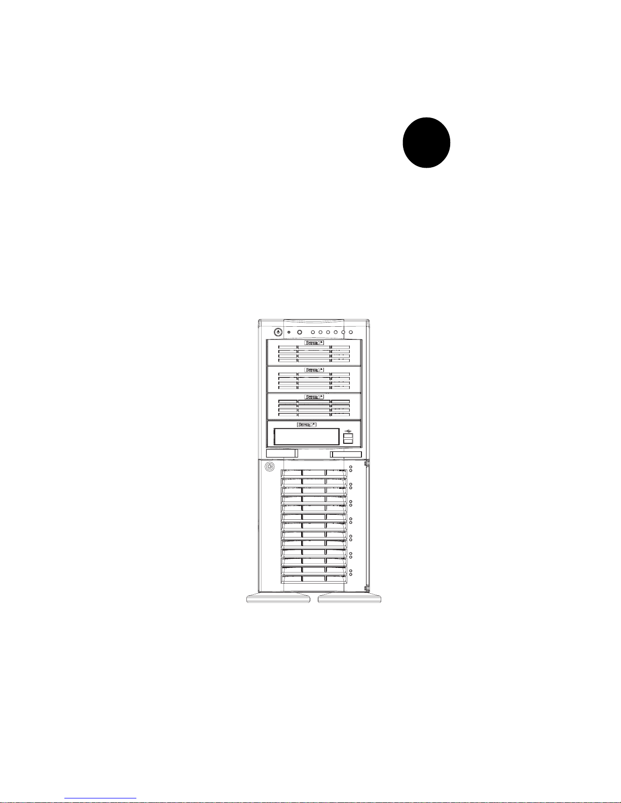
The Supermicro SuperServer 7042S-i is a high-end dual processor server
that can be utilized either in a tower or in a rackmount configuration. The
SuperServer 7042S-i is comprised of two main subsystems: the SC742i-420
high-end server chassis and the P4DSE-M dual Xeon processor mainboard.
Please refer to our web site for information on operating systems that have
been certified for use with the SuperServer 7042S-i.
In addition to the mainboard and chassis, various hardware components
have been included with the SuperServer 7042S-i, as listed below:
l Up to two (2) 603-pin Xeon 512KB L2 cache processors*
l Two (2) CPU heatsinks* (Fan-042)
l Up to 4 GB ECC registered PC1600 DDR SDRAM main memory*
l One (1) 1.44" floppy drive
l One (1) 5.25" drive bay
l One (1) ATA66 ribbon cable for IDE CD-ROM
l One (1) ATA100 ribbon cable for IDE hard drives
l One (1) USB cable for front side access
l Seven (7) 1-inch high IDE drive carriers
l One (1) I/O shield
You should also have received a User's Manual and Supermicro diskettes,
which contains several drivers and utilities.
*
Type and number depends upon the configuration ordered.
Chapter 1: Introduction
1-1

SUPERSERVER 7042S-i Manual
1-2
1-2 Server Chassis Features
The SuperServer 7042S-i is a scaleable server platform designed with some
of today's most state-of-the-art features. The following is a general outline
of the main features of the SC742i-420 server chassis.
System Power
The 7042S-i features a 420W power supply that has a redundant cooling
feature. This power unit is equipped with two fans. One runs continuously
while the other activates if the primary fan fails or if the temperature becomes too high, which also activates an alarm and illuminates the power fail
LED. An alarm reset button is located on the back of the power supply to
deactivate the power fail alarm.
Front Control Panel
The SuperServer 7042S-i's control panel provides you with system monitoring and control. LEDs indicate network activity, power supply (fan) failure,
HDD activity and SCSI drive activity. The main power button, a system
reset button and an NMI button are also included.
I/O Backplane
The SC742i-420 is an ATX form factor chassis that can be used as a tower
or mounted as a 4U rackmount server. The I/O backplane provides seven
motherboard expansion slots, one COM port, one VGA port, a parallel port,
two USB ports, PS/2 mouse and keyboard ports and an Ethernet port.
Cooling System
The SC742i-420 chassis has an innovative cooling design that includes one
9-cm hot-plug redundant system cooling fan (an additional 9-cm fan is optional) and one heavy duty 12-cm exhaust fan. The power supply includes
both a primary and a secondary fan. All fans operate continuously, except
for the secondary power supply fan, which activates only when the primary fails or the temperature becomes too high.

1-3
Chapter 1: Introduction
Mainboard Features
At the heart of the SuperServer 7042S-i lies the P4DSE-M, a dual processor
motherboard designed to provide maximum performance in cost-effective
configurations. Below are the main features of the P4DSE-M.
Processors
The P4DSE-M supports single or dual Intel Xeon 512KB L2 cache processors of up to 2.8 GHz with a 400 MHz FSB. Please refer to the support
section of our web site for a complete listing of supported processors
(http://www.supermicro.com/TechSupport.htm).
Memory
The P4DSE-M has 4 184-pin DIMM slots that can support up to 4 GB of
registered ECC PC1600 (DDR-200) SDRAM. Module sizes of 128MB, 256MB,
512MB and 1GB may be used to populate the DIMM slots. (PC2100 is also
supported, but only at 200 MHz.)
PCI Expansion Slots
The P4DSE-M has a total of seven PCI expansion slots consisting of three
64-bit 100 MHz slots and three 32-bit 33 MHz slots.
Onboard Controllers/Ports
One floppy drive controller and two onboard ATA/100 controllers, which
support up to four hard drives or ATAPI devices. The color-coded I/O ports
include a VGA port, one COM port, a parallel port, two USB ports, PS/2
mouse and keyboard ports and one 10/100 Mb Ethernet port. Two front
side USB ports are also included on the front of the chassis.
Other Features
Other onboard features that promote system health include onboard voltage
monitors, a chassis intrusion header, auto-switching voltage regulators,
chassis and CPU overheat sensors, virus protection and BIOS rescue.

SUPERSERVER 7042S-i Manual
1-4
1-4 Contacting Supermicro
Headquarters
Address: SuperMicro Computer, Inc.
980 Rock Ave.
San Jose, CA 95131 U.S.A.
Tel: +1 (408) 503-8000
Fax: +1 (408) 503-8008
Email: marketing@supermicro.com (General Information)
support@supermicro.com (Technical Support)
Web Site: www.supermicro.com
Europe
Address: SuperMicro Computer B.V.
Het Sterrenbeeld 28, 5215 ML
's-Hertogenbosch, The Netherlands
Tel: +31 (0) 73-6400390
Fax: +31 (0) 73-6416525
Email: sales@supermicro.nl (General Information)
support@supermicro.nl (Technical Support)
rma@supermicro.nl (Customer Support)
Asia-Pacific
Address: SuperMicro, Taiwan
D5, 4F, No. 16 Chien-Ba Road
Chung-Ho 235, Taipei Hsien, Taiwan, R.O.C.
Tel: +886-(2) 8226-3990
Fax: +886-(2) 8226-3991
Web Site: www.supermicro.com.tw
Technical Support:
Email: support@supermicro.com.tw
Tel: 886-2-8228-1366, ext.132 or 139

Chapter 2: Server Installation
2-1
Chapter 2
Server Installation
2-1 Overview
This chapter provides a quick setup checklist to get your SuperServer
7042S-i up and running. Following these steps in the order given should
enable you to have the system operational within a minimum amount of time.
This quick setup assumes that your SuperServer 7042S-i system has come
to you with the processors and memory preinstalled. If your system is not
already fully integrated with a motherboard, processors, system memory
etc., please turn to the chapter or section noted in each step for details on
installing specific components. The 7042S-i may be employed either as a
tower or mounted in a rack as a 4U rackmount chassis. If using it as a
server, please read Server Precautions in the next section and then skip
ahead to Section 2-5.
2-2 Unpacking the SuperServer 7042S-i
You should inspect the box the SuperServer 7042S-i was shipped in and
note if it was damaged in any way. If the server itself shows damage you
should file a damage claim with the carrier who delivered it.
Decide on a suitable location for the SuperServer 7042S-i. It should be
situated in a clean, dust-free area that is well ventilated. Avoid areas
where heat, electrical noise and electromagnetic fields are generated. You
will also need it placed near a grounded power outlet. Read the Rack and
Server Precautions in the next section.
2-3 Preparing for Setup
The box the SuperServer 7042S-i was shipped in may include two sets of
rail assemblies, two rail mounting brackets and mounting screws needed
for installing the system into a rack (optional kit). Follow the steps in the
order given to complete the installation process in a minimum amount of time.
Please read this section in its entirety before you begin the installation
procedure outlined in the sections that follow.
2-2
SUPERSERVER 7042S-i Manual
Choosing a Setup Location:
- Leave enough clearance in front of the system to enable you to open
the front door completely (~25 inches).
- Leave approximately 30 inches of clearance in the back of the system
to allow for sufficient airflow and ease in servicing.
Rack Precautions:
- Ensure that the leveling jacks on the bottom of the rack are fully
extended to the floor with the full weight of the rack resting on them.
- In single rack installation, stabilizers should be attached to the rack.
- In multiple rack installations, the racks should be coupled together.
- Always make sure the rack is stable before extending a component
from the rack.
- You should extend only one component at a time - extending two or
more simultaneously may cause the rack to become unstable.
Server Precautions:
- Review the electrical and general safety precautions in Chapter 4.
- Determine the placement of each component in the rack
before
you
install the rails.
- Install the heaviest server components on the bottom of the rack
first, and then work up.
- Use a regulating uninterruptible power supply (UPS) to protect the
server from power surges, voltage spikes and to keep your
system operating in case of a power failure.
- Allow the hot plug SCSI drives and power supply units to cool before
touching them.
- Always keep the rack's front door and all panels and components on
the servers closed when not servicing to maintain proper cooling.
! !
Warnings and Precautions!
Chapter 2: Server Installation
2-3
2-4 Installing the SuperServer 7042S-i into a Rack
This section provides information on installing the SuperServer 7042S-i
into a rack unit. (If the 7042S-i has already been mounted into a rack or
if you are using it as a tower, you can skip ahead to Sections 2-5 and 2-
6.) There are a variety of rack units on the market, which may mean the
assembly procedure will differ slightly. The following is a guideline for
installing the 7042S-i into a rack with the rack rails provided in the rack
mount kit. You should also refer to the installation instructions that came
with the rack unit you are using.
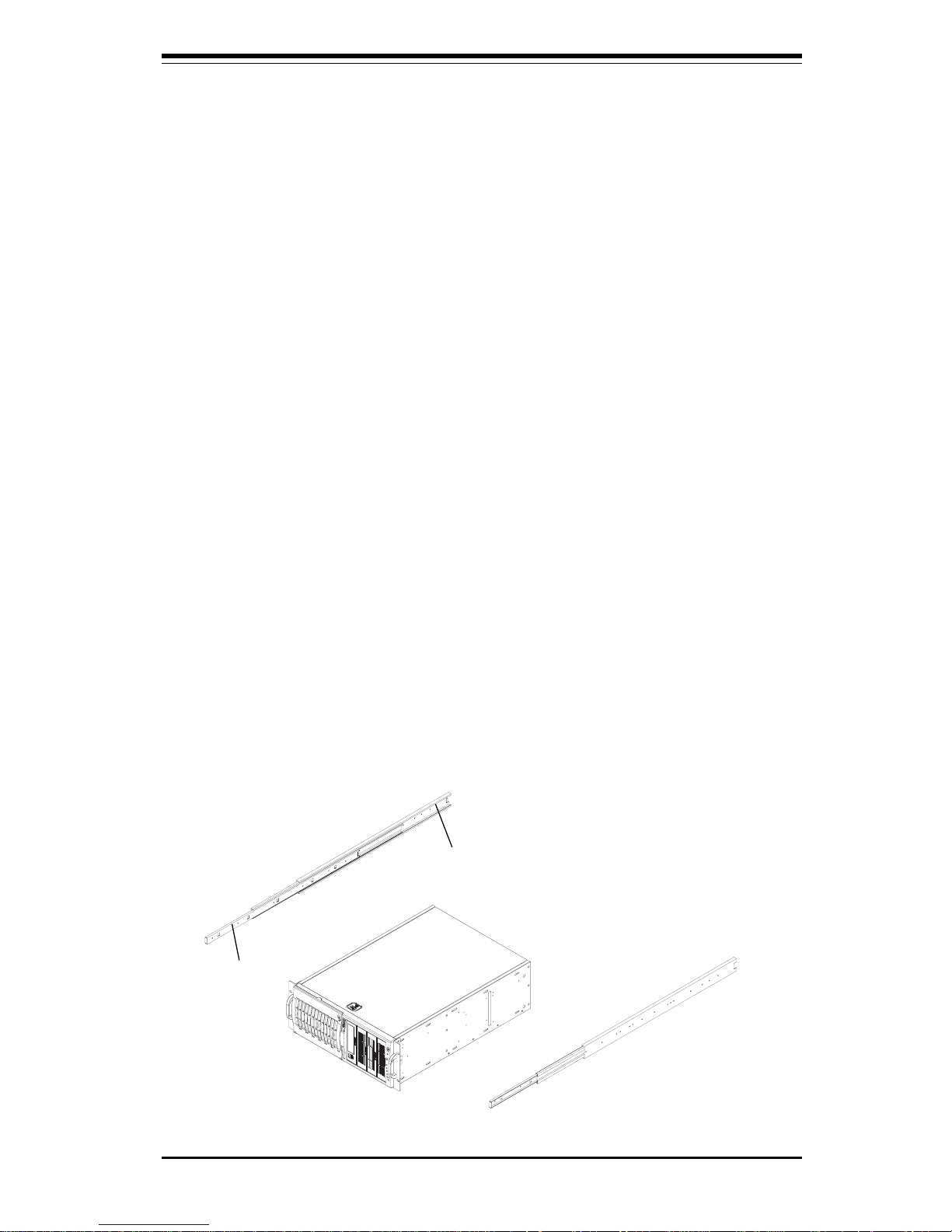
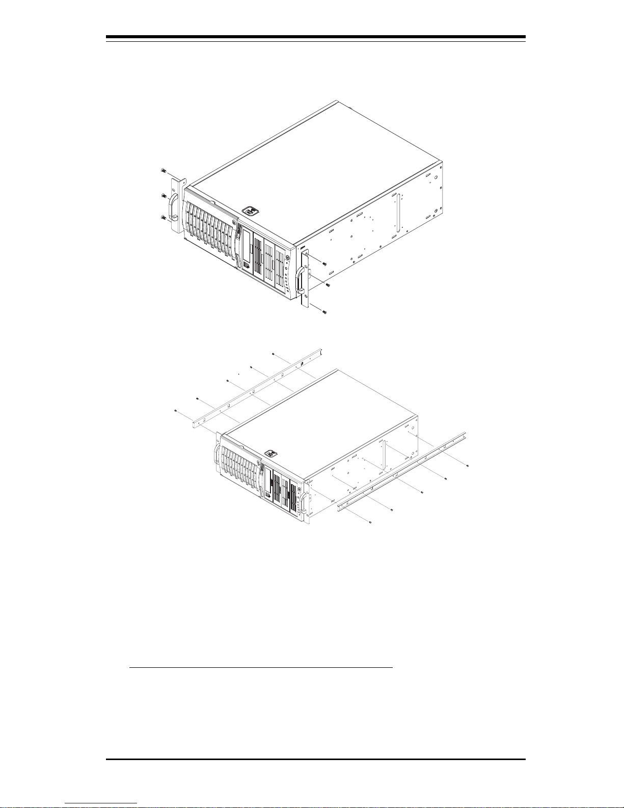
Identifying the Sections of the Rack Rails:
The 7042S-i rackmount kit (CSE-PT26 or CSE-PT26B - black) includes two
rack rail assemblies. Each of these assemblies consist of three sections:
an inner fixed chassis rail that secures to the 7042S-i (A), an outer fixed
rack rail that secures directly to the rack itself (B) and a sliding rail guide
sandwiched between the two, which should remain attached to the fixed
rack rail (see Figure 2-1.) The A and B rails must be detached from each
other to install. Two chassis handles are also included with the rail kit.
To remove the fixed chassis rail (A), pull it out as far as possible - you
should hear a "click" sound as a locking tab emerges from inside the rail
assembly and locks the inner rail. Depress the locking tab to pull the
inner rail completely out. Do this for both assemblies.
Figure 2-1. Identifying the Sections of the Rack Rails
B
A
2-4
SUPERSERVER 7042S-i Manual
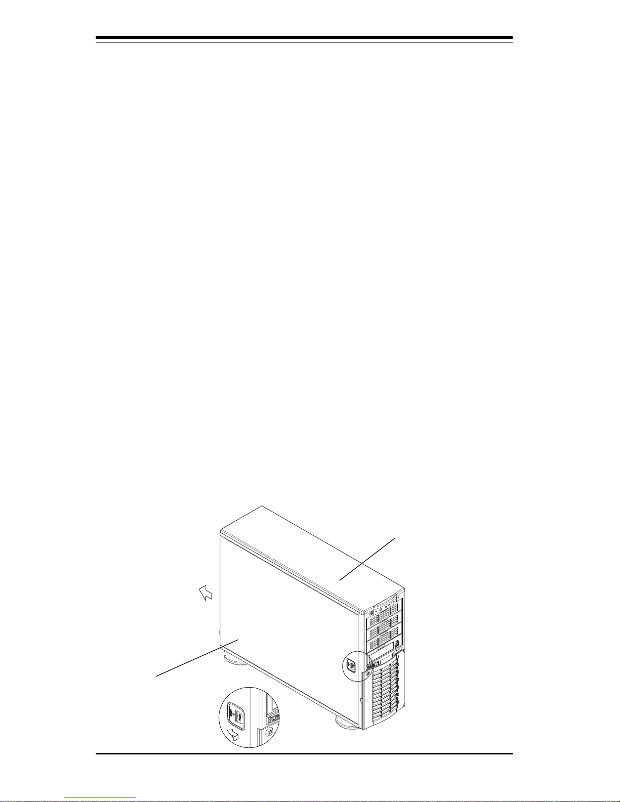
Installing the Chassis Rails:
You will need to remove the top cover, the top/left cover and the feet to add
rack rails to the chassis. First, remove the top/left cover by pushing the
release tab in the center of the cover lip while pushing the cover toward
the rear of the chassis (see Figure 2-2). After the cover stops, lift it off.
Each chassis foot has a single screw. Remove the screw then depress
the foot’s locking tab from the inside of the chassis to slide the foot off.
Next, remove the top cover. You should see a release tab at the middle of
the lip. Push this tab toward the chassis edge while pushing the cover
toward the front of the chassis. It should then lift right off. You can now
attach rack rails to the top and bottom (now the sides) of the chassis. First
add the rack handles as shown in Figure 2-3. Then position the fixed
chassis rail sections you just removed along the side of the 7042S-i making
sure the screw holes line up. Note that these two rails are left/right specific. Screw the rail securely to the side of the chassis (see Figure 2-4).
Repeat this procedure for the other rail on the other side of the chassis.
You will also need to attach the rail brackets when installing into a telco
rack.
Locking Tabs: As mentioned, both chassis rails have a locking tab,
which serves two functions. The first is to lock the server into place
when installed and pushed fully into the rack, which is its normal position.
Secondly, these tabs also lock the server in place when fully extended
from the rack. This prevents the server from coming completely out of
the rack when you pull it out for servicing.
Figure 2-2. Removing the Top/Left Cover
Top/left cover
Top cover
Chapter 2: Server Installation
2-5
Installing the Rack Rails:
Determine where you want to place the SuperServer 7042S-i in the rack.
(See Rack and Server Precautions in Section 2-3.) Position the fixed rack
rail/sliding rail guide assemblies at the desired location in the rack, keeping
the sliding rail guide facing the inside of the rack. Screw the assembly
securely to the rack using the brackets provided. Attach the other assembly to the other side of the rack, making both are at the exact same height
and with the rail guides facing inward.
Figure 2-4. Installing the Rails to the Chassis
Figure 2-3. Installing the Rack Handles
2-6
SUPERSERVER 7042S-i Manual
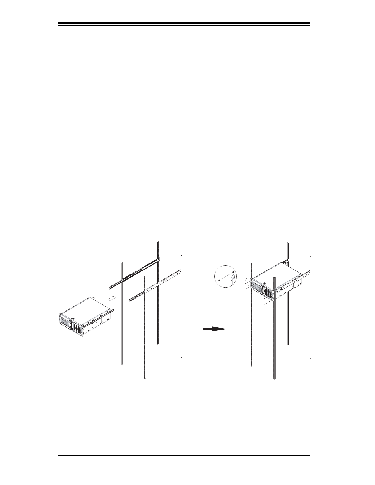
Figure 2-5. Installing the Server into a Rack
Installing the Server into the Rack:
You should now have rails attached to both the chassis and the rack unit.
The next step is to install the server into the rack. Do this by lining up the
rear of the chassis rails with the front of the rack rails. Slide the chassis
rails into the rack rails, keeping the pressure even on both sides (you may
have to depress the locking tabs when inserting).
When the server has been pushed completely into the rack, you should
hear the locking tabs "click". Finish by inserting and tightening the thumbscrews that hold the front of the server to the rack (see Figure 2-5).

Chapter 2: Server Installation
2-7
2-5 Checking the Motherboard Setup
After setting up the the 7042S-i, you will need to open the unit to make
sure the motherboard is properly installed and all the connections have
been made.
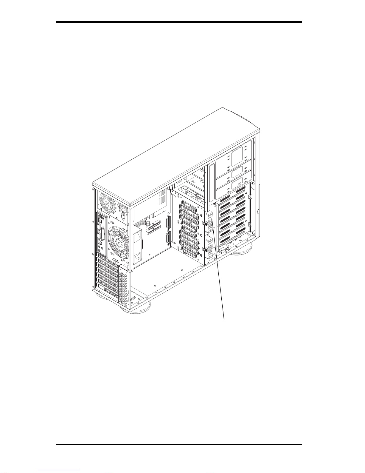
1. Accessing the inside of the 7042S-i (see Figure 2-6):
(If rack mounted, first release the retention screws that secure the unit
to the rack. Grasp the two handles on either side and pull the unit
straight out until it locks (you will hear a "click").) Depress the two
buttons on the top (side if tower) of the chassis to release the cover.
There is a large rectangular recess in the middle front of the cover to
help you push the cover away from you until it stops. You can then lift
the cover from the chassis to gain full access to the inside of the server.
2. Check the CPUs (processors):
You should have one or two processors already installed into the
system board. Each processor should have its own heatsink attached.
See Section 5-5 for instructions on processor installation.
3. Verify the proper CPU clock ratio setting:
If the CPU speed is not automatically detected you will need to set the
correct speed with the BIOS Setup utility. See the CPU Speed and Frequency Ratio settings in BIOS (Chapter 7) to set the processor speed.
4. Check the system memory:
Your 7042S-i server system may have come with system memory already installed. Make sure all DIMMs are fully seated in their slots. For
details on adding system memory, refer to Section 5-6.
5. Installing add-on cards:
If desired, you can install add-on cards to the system. See Section 5-7
for details on installing PCI add-on cards.
2-8
SUPERSERVER 7042S-i Manual
Figure 2-6. Accessing the Inside of the SuperServer 7042S-i
Optional Fan

Chapter 2: Server Installation
2-9
6. Check all cable connections and airflow:
Make sure all power and data cables are properly connected and not
blocking the chassis airflow. See Section 5-3 for details on cable connections.
2-6 Checking the Drive Bay Setup
Next, you should check to make sure the peripheral drives have been prop
erly installed and all connections have been made.
1. Accessing the drive bays:
All drives can be accessed from the front of the server. For servicing
the CD-ROM, IDE hard drives and floppy drives, you will need to remove
the top/left chassis cover.
2. Installing components into the 5.25" drive bay:
To install components into the 5.25" drive bays, you must first remove the
top/left chassis cover as described in the previous section. Refer to
Chapter 6 for details.
3. Installing CD-ROM and floppy disk drives:
Refer to Chapter 6 if you need to reinstall a CD-ROM and/or floppy disk
drive to the system.
4. Check the IDE disk drives:
Depending upon your system's configuration, your system may have one
or more drives already installed. If you need to install IDE drives, please
refer to Chapter 6.
5. Check the airflow:
Airflow is provided by one 9-cm cooling fan (a second 9-cm fan is optional) and a heavy duty 12-cm exhaust fan. The system component
layout was carefully designed to promote sufficient airflow through the
4U rackmount space. Also note that all power and data cables have

2-10
SUPERSERVER 7042S-i Manual
been routed in such a way that they do not block the airflow generated
by the fans. Keep this in mind when you reroute them after working on
the system.
6. Supplying power to the system:
The last thing you must do is to provide input power to the system. Plug
the power cord from the power supply units into a high-quality power
strip that offers protection from electrical noise and power surges. It is
recommended that you use an uninterruptible power supply (UPS). Finally, depress the power on button on the front of the chassis.

Chapter 3: System Interface
3-1
Chapter 3
System Interface
3-1 Overview
There are several LEDs on the control panel as well as two for each SCSI
drive carrier and the LAN (Ethernet) ports. These LEDs are to keep you
constantly informed of the overall status of the system and the activity and
health of specific components. There are also three buttons on the chassis
control panel.
3-2 Control Panel Buttons
There are three push-button buttons located on the front of the chassis.
These are (in order from left to right) a power on/off button, an NMI (NonMaskable Interrupt) button and a reset button.
l POWER: This is the main power button, which is used to apply or turn
off the main system power. Turning off system power with this button
removes the main power but keeps standby power supplied to the system.
l NMI: NMI stands for "non-maskable interrupt". Pressing this button
issues a non-maskable interrupt to force the server into a halt state. This is
used for diagnostic purposes, and allows you to perform a memory download to determine the cause of a problem.
SUPERSERVER 7042S-i User's Manual
3-2
l RESET: Use the reset button to reboot the system.
3-3 Control Panel LEDs
The control panel located on the front of the SC742S-420 chassis has six
LEDs that provide you with critical information related to different parts of
the system. This section explains what each LED indicates when illuminated and any corrective action you may need to take.
l Power: Indicates external power is being supplied to the system's
power supply unit. This LED should normally be illuminated when the system is operating.
l HDD: Indicates IDE channel activity. On the SuperServer 7042S-i, this
LED indicates CD-ROM drive activity when flashing.
l NIC1: Indicates network activity on LAN1 when flashing.
l NIC2: Indicates network activity on LAN2 when flashing.
NIC1
NIC2
Chapter 3: System Interface
3-3
l Overheat: Indicates an overheat condition in the chassis. This may
be caused by cables obstructing the airflow in the system or the ambient
room temperature being too warm. You should also check to make sure
that the chassis covers are installed and that all fans are present and
operating normally. Finally, verify that the heatsinks are installed properly
(see Section 5-5 and Figure 5-4).
l Power Fail: Indicates a power supply fan has failed. The power
supply will continue to operate with a secondary backup fan but will need
to be replaced. Refer to Chapter 6 for details on replacing the power
supply. This LED should be off when the system is operating normally.
3-4 LAN (Ethernet) Port LEDs
The LAN port (located beside the VGA port) has a yellow and a green LED.
See the table below for the functions associated with these LEDs.
LED
Color
Green
Yellow
Definition
Connected
Active
100 Mb LAN LED
Indicators

SUPERSERVER 7042S-i User's Manual
3-4
Chapter 4: System Safety
4-1
Chapter 4
System Safety
4-1 Electrical Safety Precautions
!
Basic electrical safety precautions should be followed to protect
yourself from harm and the SuperServer 7042S-i from damage:
l Be aware of the locations of the power on/off switch on the
chassis as well as the room's emergency power-off switch,
disconnection switch or electrical outlet. If an electrical accident
occurs, you can then quickly remove power from the system.
l Do not work alone when working with high voltage components.
l Power should always be disconnected from the system when
removing or installing main system components, such as the
motherboard, memory modules and the CD-ROM and floppy drives.
When disconnecting power, you should first power down the
system with the operating system and then unplug the power cords
of all the power supply units in the system.
l When working around exposed electrical circuits, another person
who is familiar with the power-off controls should be nearby to
switch off the power if necessary.
l Use only one hand when working with powered-on electrical
equipment. This is to avoid making a complete circuit, which will
cause electrical shock. Use extreme caution when using metal
tools, which can easily damage any electrical components or circuit
boards they come into contact with.
l Do not use mats designed to decrease electrostatic discharge as
protection from electrical shock. Instead, use rubber mats that
have been specifically designed as electrical insulators.
SUPERSERVER 7042S-i Manual
4-2
4-2 General Safety Precautions
Follow these rules to ensure general safety:
l Keep the area around the SuperServer 7042S-i clean and free of
clutter.
l The SuperServer 7042S-i weighs approximately 54 lbs (24.2 kg)
when fully loaded. When lifting the system, two people at either
end should lift slowly with their feet spread out to distribute the
weight. Always keep your back straight and lift with your legs.
l Place the chassis top/side cover and any system components that
have been removed away from the system or on a table so that
they won't accidentally be stepped on.
l While working on the system, do not wear loose clothing such as
neckties and unbuttoned shirt sleeves, which can come into contact
with electrical circuits or be pulled into a cooling fan.
l Remove any jewelry or metal objects from your body, which are
excellent metal conductors that can create short circuits and harm
you if they come into contact with printed circuit boards or areas
where power is present.
!
l The power supply power cord must include a grounding plug and
must be plugged into grounded electrical outlets.
l Motherboard Battery: CAUTION - There is a danger of explosion if
the onboard battery is installed backwards, which will reverse its
polarities. The positive side of the battery should be facing up and
the negative side should facing the motherboard. This battery must
be replaced only with the same or an equivalent type recommended
by the manufacturer. Dispose of used batteries according to the
manufacturer's instructions.
l CD-ROM Laser: CAUTION - this server may have come equipped
with a CD-ROM drive. To prevent direct exposure to the laser beam
and hazardous radiation exposure, do not open the enclosure or
use the unit in any unconventional way.
 Loading...