

Page 1
®
SUPER
USER’S MANUAL
1.0a
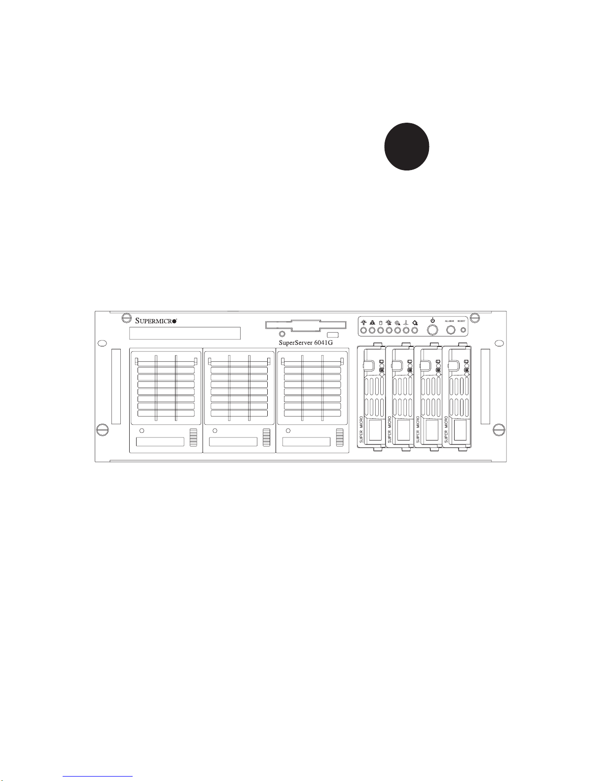
SUPERSERVER 6041G
Page 2

The information in this User’s Manual has been carefully reviewed and is believed to be
accurate. The vendor assumes no responsibility for any inaccuracies that may be
contained in this document, makes no commitment to update or to keep current the
information in this manual, or to notify any person or organization of the updates.
Please
Note: For the most up-to-date version of this manual, please see our
web site at www.supermicro.com.
SUPERMICRO COMPUTER reserves the right to make changes to the product described in
this manual at any time and without notice. This product, including software, if any, and
documentation may not, in whole or in part, be copied, photocopied, reproduced, translated
or reduced to any medium or machine without prior written consent.
IN NO EVENT WILL SUPERMICRO COMPUTER BE LIABLE FOR DIRECT, INDIRECT,
SPECIAL, INCIDENTAL, SPECULATIVE OR CONSEQUENTIAL DAMAGES ARISING FROM
THE USE OR INABILITY TO USE THIS PRODUCT OR DOCUMENTATION, EVEN IF
ADVISED OF THE POSSIBILITY OF SUCH DAMAGES. IN PARTICULAR, THE VENDOR
SHALL NOT HAVE LIABILITY FOR ANY HARDWARE, SOFTWARE, OR DATA STORED
OR USED WITH THE PRODUCT, INCLUDING THE COSTS OF REPAIRING, REPLACING,
INTEGRATING, INSTALLING OR RECOVERING SUCH HARDWARE, SOFTWARE, OR
DATA.
Any disputes arising between manufacturer and customer shall be governed by the laws of
Santa Clara County in the State of California, USA. The State of California, County of
Santa Clara shall be the exclusive venue for the resolution of any such disputes.
Supermicro's total liability for all claims will not exceed the price paid for the hardware
product.
Unless you request and receive written permission from SUPER MICRO COMPUTER, you
may not copy any part of this document.
Information in this document is subject to change without notice. Other products and
companies referred to herein are trademarks or registered trademarks of their respective
companies or mark holders.
Copyright © 2005 by SUPER MICRO COMPUTER INC.
All rights reserved.
Printed in the United States of America.
Page 3

Preface
About This Manual
This manual is written for professional system integrators and PC technicians. It provides information for the installation and use of the SuperServer 6041G. Installation and maintainance should be performed by experienced technicians only.
The SuperServer 6041G is a high-end dual processor 4U rackmount server
based on the SC840 4U rackmount server chassis and the Super P3TDE6, a
dual processor motherboard that supports one or two Pentium III FCPGA
processors and 4GB registered ECC DIMM memory.
Manual Organization
Chapter 1: Introduction
The first chapter provides a checklist of the main components included with
the server system and describes the main features of the P3TDE6
mainboard and the SC840 chassis, which make up the SuperServer 6041G.
Chapter 2: Server Installation
This chapter describes the steps necessary to install the SuperServer
6041G into a rack and check out the server configuration prior to powering
up the system. If your server was ordered without processor and memory
components, this chapter will refer you to the appropriate sections of the
manual for their installation.
Chapter 3: System Interface
Refer here for details on the system interface, which includes the functions
and information provided by the control panel on the chassis as well as
other LEDs located throughout the system.
Chapter 4: System Safety
You should thoroughly familiarize yourself with this chapter for a general
overview of safety precautions that should be followed when installing and
servicing the SuperServer 6041G.
iii
Preface
Page 4

SUPERSERVER 6041G Manual
iv
Chapter 5: Advanced Motherboard Setup
Chapter 5 provides detailed information on the motherboard, including the
locations and functions of connections, headers, jumpers and IRQs. Refer
to this chapter when adding or removing processors or main memory and
when reconfiguring the motherboard.
Chapter 6: Advanced Chassis Setup
Refer to Chapter 6 for detailed information on the 4U rackmount server
chassis. You should follow the procedures given in this chapter when
installing, removing or reconfiguring SCSI or peripheral drives and when
replacing system power supply units and cooling fans.
Chapter 7: BIOS
The BIOS chapter includes an introduction to BIOS and provides detailed
information on running the CMOS Setup Utility.
Appendix A: BIOS Error Beep Codes and Messages
Appendix B: POST Diagnostic Error Messages
Appendix C: List of Figures
Appendix D: System Specifications
Page 5
v
Manual Organization
Introduction
Chp1
Installation System
Interface
System
Safety
Motherboard
Details
Chassis
Details
BIOS and
Setup Routine
Chp3Chp2
Chp5
Chp4
Chp6
Appendices
Overview
Chassis
Mainboard
Contact Info
Overview
Precautions
Setup
Rack
Installation
Overview
Switches
Cntrl Pnl LEDs
SCSI LEDs
Pwr Sply LEDs
MB LEDs
Static Sensitive
MB Installation
Cables
CPU Installation
MEC Install.
PCI Cards
MB Layout
Connectors
DIP Switches
Jumper
Settings
I/O Ports/IDE/
SCSI Conn.
IRQs
Static Sensitive
Control Panel
System Fans
Drive Bay Inst.
Power Supply
Chp7 App. A/B/C/D
Introduction
BIOS Features
Running Setup
Electrical Safety
General Safety
ESD Safety
BIOS Beep
Codes
Post Diag. Error
Messages
List of Figures
System Specs
Preface
Page 6

SUPERSERVER 6041G Manual
vi
Table of Contents
Preface
About This Manual ...................................................................................................... iii
Manual Organization ................................................................................................... iii
Manual Organization (Flowchart)............................................................................. v
Chapter 1: Introduction to the SuperServer 6041G
1-1 Overview ......................................................................................................... 1-1
1-2 Server Chassis Features.............................................................................. 1-2
1-3 Mainboard Features ....................................................................................... 1-4
1-4 Contacting Supermicro .................................................................................. 1-6
Chapter 2: Server Installation
2-1 Overview ......................................................................................................... 2-1
2-2 Unpacking the SuperServer 6041G ............................................................ 2-1
2-3 Preparing for Setup ....................................................................................... 2-1
Choosing a Setup Location .................................................................... 2-2
Rack Precautions ..................................................................................... 2-2
Server Precautions.................................................................................. 2-2
2- 4 Installing the SuperServer 6041G into a Rack .......................................... 2-3
Identifying the Sections of the Rack Rails .......................................... 2-3
Installing the Chassis Rails ..................................................................... 2-4
Installing the Rack Rails .......................................................................... 2-4
Installing the Server into the Rack ........................................................ 2-5
2- 5 Checking the Motherboard Setup ................................................................ 2-7
2-6 Checking the Drive Bay Setup ..................................................................... 2-9
Chapter 3: System Interface
3-1 Overview ......................................................................................................... 3-1
3-2 Control Panel Switches................................................................................. 3-1
Power ........................................................................................................ 3-1
Alarm.......................................................................................................... 3-1
Reset.......................................................................................................... 3-1
3-3 Control Panel LEDs ........................................................................................ 3-2
Power ........................................................................................................ 3-2
NIC .............................................................................................................. 3-2
HDD ............................................................................................................ 3-2
PWR Fault.................................................................................................. 3-2
Page 7

Fan Fail...................................................................................................... 3-3
Overheat ................................................................................................... 3-3
SCA Channel ............................................................................................ 3-3
3- 4 SCSI Drive Carrier LEDs ............................................................................... 3-4
3-5 Power Supply LEDs ....................................................................................... 3-4
3- 6 Motherboard LED ............................................................................................ 3-4
Chapter 4: System Safety
4-1 Electrical Safety Precautions ........................................................................ 4-1
4-2 General Safety Precautions .......................................................................... 4-2
4- 3 ESD Precautions.............................................................................................. 4-3
Chapter 5: Advanced Motherboard Setup
5- 1 Handling the P3TDE6 Motherboard ............................................................... 5-1
5- 2 Motherboard Installation ................................................................................. 5-2
5-3 Connecting Cables .......................................................................................... 5-4
Connecting Data Cables .......................................................................... 5-4
Connecting Power Cables....................................................................... 5-4
Connecting the Control Panel ................................................................. 5-5
5- 4 Port/Control Panel Connector Locations ...................................................... 5-6
5-5 Processor Installation ..................................................................................... 5-7
Removing Pentium III 370-pin Processors ........................................... 5-8
5-6 Installing DIMMs................................................................................................ 5-9
5- 7 Adding PCI Cards .......................................................................................... 5-10
Super P3TDE6 Layout ........................................................................... 5-12
P3TDE6 Quick Reference ..................................................................... 5-13
5-8 Connector Definitions ................................................................................... 5-14
Power Supply Connectors ................................................................... 5-14
Secondary Power Connector............................................................... 5-14
Power Button .......................................................................................... 5-14
Reset........................................................................................................ 5-15
Power Fail LED ...................................................................................... 5-15
Overheat LED ......................................................................................... 5-15
NIC1 LED ................................................................................................. 5-15
HDD (IDE) LED ......................................................................................... 5-16
Power LED ............................................................................................... 5-16
Fan Fail LED............................................................................................ 5-16
I2C.............................................................................................................. 5-16
Chassis Intrusion ................................................................................... 5-16
Keyboard Lock ....................................................................................... 5-17
vii
Table of Contents
Page 8

SUPERSERVER 6041G Manual
viii
Speaker ................................................................................................... 5-17
USB3 ........................................................................................................ 5-17
Fan Headers ........................................................................................... 5-17
ATX PS/2 Keyboard and Mouse Ports ................................................5-18
Universal Serial Bus Connector .......................................................... 5-18
Ethernet Port........................................................................................... 5-18
Wake-On-LAN ........................................................................................ 5-18
Wake-On-Ring ........................................................................................ 5-19
SLED1 (SCSI LED) ................................................................................. 5-19
Chassis Intrusion .................................................................................... 5-19
I2C Header ................................................................................................ 5-19
Serial Ports ............................................................................................. 5-20
5- 9 DIP Switch Settings ...................................................................................... 5-20
DIP Switch 1: Core/Bus Ratio .............................................................. 5-20
5-10 Jumper Settings............................................................................................. 5-21
Explanation of Jumpers ......................................................................... 5-21
CMOS Clear.............................................................................................. 5-21
Front Side Bus Speed ........................................................................... 5-21
SCSI Termination Enable/Disable.......................................................... 5-22
LVD Channel A SCSI Termination Enable/Disable............................. 5-22
LVD Channel B SCSI Termination Enable/Disable ............................. 5-22
Speaker Enable/Disable ......................................................................... 5-22
LAN 1 Enable/Disable ............................................................................5-23
Thermal Fan Enable/Disable.................................................................. 5-23
PCI Speed Setting ................................................................................... 5-23
VGA Enable/Disable ............................................................................... 5-23
5-11 Parallel Port, Floppy/HDD and SCSI Connections .................................... 5-24
Parallel Port Connector ......................................................................... 5-24
Floppy Connector ................................................................................... 5-24
IDE Connectors ...................................................................................... 5-25
Ultra160 SCSI Connectors ..................................................................... 5-25
5-12 IRQs ................................................................................................................. 5-26
Chapter 6: Advanced Chassis Setup
6-1 Static-Sensitive Devices ................................................................................ 6-1
6-2 Control Panel .................................................................................................... 6-2
6-3 System Fans .................................................................................................... 6-4
System Fan Failure .................................................................................. 6-4
Replacing System Cooling Fans ............................................................ 6-5
Page 9

Table of Contents
ix
Replacing System Exhaust Fans .......................................................... 6-6
6- 4 Drive Bay Installation/Removal ...................................................................... 6-6
Accessing the Drive Bays ..................................................................... 6-6
SCSI Drive Installation............................................................................. 6-7
CD-ROM and Floppy Drive Installation ............................................... 6-10
6-5 Power Supply Units ...................................................................................... 6-11
Power Supply Failure ........................................................................... 6-11
Replacing Power Units ......................................................................... 6-11
Chapter 7: BIOS
7- 1 Introduction....................................................................................................... 7-1
7- 2 BIOS Features.................................................................................................. 7-2
7- 3 Running Setup.................................................................................................. 7-2
7-4 Advanced BIOS Setup .................................................................................... 7-4
7- 5 Chipset Setup................................................................................................. 7-15
7-6 PCI/Plug and Play Setup ............................................................................... 7-18
7-7 Power Setup .................................................................................................. 7-20
7- 8 Boot Setup...................................................................................................... 7-23
7-9 Security Setup ............................................................................................... 7-25
7-10 Exit Setup .......................................................................................................7-27
Appendices:
Appendix A: BIOS Error Beep Codes and Messages ....................................... A-1
Appendix B: AMIBIOS POST Diagnostic Error Messages .................................. B-1
Appendix C: List of Figures ....................................................................................C-1
Appendix D: System Specifications ...................................................................... D-1
Page 10

Notes
SUPERSERVER 6041G User's Manual
x
Page 11

Chapter 1
Introduction to the SuperServer 6041G
1-1 Overview
The Supermicro SuperServer 6041G is a high-end dual processor, 4U
rackmount server that features some of the most advanced technology
currently available. The SuperServer 6041G is comprised of two main subsystems: the SC840 4U rackmount chassis and the P3TDE6 dual 370-pin
Pentium III processor mainboard. Please refer to our web site for information on operating systems that have been certified for use with the SuperServer 6041G.
In addition to the mainboard and chassis, various hardware components
may have been included with your SuperServer 6041G, as listed below.
z One (1) 1.44" floppy drive
z One (1) slim CD-ROM drive
z One (1) Supermicro CD containing various drivers and utilities
z One (1) Control Panel PCB
z Rackmount hardware (with screws):
Two (2) rack rail assemblies
Four (4) brackets for mounting the rack rails to the rack
z One (1) SCA backpanel
z Four (4) SCA SCSI drive carriers
z SCSI Accessories:
One (1) internal and one (1) external Ultra160 SCSI cable
One (1) set of SCSI driver diskettes
One (1) SCSI manual
One (1) System manual
You should also have received this User's Manual and several Supermicro
diskettes, which contains various drivers and utilities.
Chapter 1: Introduction
1-1
Page 12

SUPERSERVER 6041G Manual
1-2
1-2 Server Chassis Features
The SuperServer 6041G is a high-end, scaleable 4U rackmount server platform designed with today's most state-of-the-art features. The following is
a general outline of the main features of the SC860 chassis.
System Power
A dual redundant power supply system consisting of two 300W units to
provide 300W of continuous power with 300W of backup. (This dual redundant power supply system can be upgraded to a triple redundant system.) If any one of the two power units fail you will be notified by alarm
and LED, and the backup unit will automatically activate. These are hot-plug
units that can be replaced without powering down the system.
SCSI Subsystem
The SCSI subsystem supports 4 68-pin SCA Ultra160 SCSI hard drives.
(Any standard 1" drives are supported. SCA = Single Connection Attachment.) The SCSI drives are connected to a SAF-TE compliant SCA
backplane that provides power, bus termination and configuration settings.
The SCSI drives are also hot-swap units. A RAID controller card can be
used with the SCA backplanes to provide data security.
Note: The operating system you use must have RAID support to enable the
hot-swap capability of the SCSI drives.
Page 13
1-3
Chapter 1: Introduction
Control Panel
The SuperServer 6041G's detailed control panel provides comprehensive
system monitoring and control. LEDs indicate network activity, power supply failure, fan failure, fan status, SCSI drive activity and failure and SCA
backplane overheat conditions. The control panel also includes a main
power button, a system reset button and an alarm reset switch.
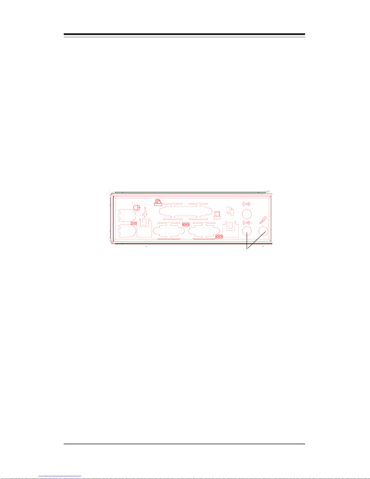
I/O Shield
The SC840 is a 4U rackmount chassis. Its I/O shield provides seven motherboard expansion slots, two COM ports, a parallel port, two USB ports, PS/
2 mouse and keyboard ports, and an Ethernet port. (See Figure 1-1.)
Cooling System
The SC840 chassis has an innovative cooling design that includes four 9cm hot-plug system cooling (intake) fans and one 9-cm hot-plug exhaust
fan. All system fans operate continuously to provide optimal cooling for add
on cards, memory and processors. If one fails, an alarm is activated and
the RPM of the remaining fans increase to compensate and maintain sufficient airflow.
Figure 1-1. I/O Shield
Sound holes not present on the 6041
Page 14

SUPERSERVER 6041G Manual
1-4
1-3 Mainboard Features
At the heart of the SuperServer 6041G lies the P3TDE6, a dual processor
motherboard designed to provide maximum performance in a two-way system. Below are the main features of the P3TDE6.
Processors
The P3TDE6 supports dual Pentium III 500 - 1.26+ GHz MHz 100/133 MHz
FSB processors. Please refer to the support section of our web site for a
complete listing of supported processors (http://www.supermicro.com/
TechSupport.htm).
Memory
Your P3TDE6 has four DIMM slots that can support up to 4 GB of ECC
registered DIMM. Module sizes of 128MB, 256MB, 512MB and 1 GB may be
populatd in the slots. The P3TDE6 supports two-way interleaved memory.
Notes on Memory:
Note 1: The memory speed must match the front side bus (FSB) speed
being used (i.e. both 133 MHz or both 100 MHz).
Note 2: Memory Modules must be installed in pairs (first in the two slots of
Bank0 and then in both slots of Bank1, if 4 DIMMs are needed).
Onboard SCSI
Onboard SCSI is provided with an Adaptec AIC-7899 SCSI controller chip,
which supports dual channel, Ultra160 SCSI at a burst throughput rate of
160 MB/sec for each channel. The P3TDE6 provides three SCSI ports: two
68-pin LVD Ultra160 connectors (on channels A and B) and one 50-pin
Legacy SCSI connector (shared with channel B.)
Page 15

1-5
Chapter 1: Introduction
Expansion Slots
The P3TDE6 has a total of six PCI expansion slots that consist of two 64-bit
3.3 V 66 MHz slots and four 64-bit 5V 33 MHz slots. These PCI slots run on
two separate data buses to provide a total I/O bandwidth of 792 MB/sec. In
addition to the PCI slot, there is also an AGPx2 Pro slot on board.
Onboard Controllers/Ports
An onboard IDE controller supports one floppy drive and up to four
UDMA/33 hard drives or ATAPI devices. Onboard I/O ports include two
COM ports, a parallel port, two USB ports, PS/2 mouse and keyboard ports,
a video (monitor) port and a 10/100 MB Ethernet port.
Onboard Graphics
The 6041G includes an 8 MB ATI Rage XL video card for superior graphics
capabilities.
Other Features
Other onboard features that promote system health include eight voltage
monitors, a chassis intrusion header, auto-switching voltage regulators,
chassis and CPU overheat sensors, virus protection and BIOS rescue.
Page 16

SUPERSERVER 6041G Manual
1-6
1-4 Contacting Supermicro
Headquarters
Address: SuperMicro Computer, Inc.
980 Rock Ave.
San Jose, CA 95131 U.S.A.
Tel: +1 (408) 503-8000
Fax: +1 (408) 503-8008
Email: marketing@supermicro.com (General Information)
support@supermicro.com (Technical Support)
Web Site: www.supermicro.com
Europe
Address: SuperMicro Computer B.V.
Het Sterrenbeeld 28, 5215 ML
's-Hertogenbosch, The Netherlands
Tel: +31 (0) 73-6400390
Fax: +31 (0) 73-6416525
Email: sales@supermicro.nl (General Information)
support@supermicro.nl (Technical Support)
rma@supermicro.nl (Customer Support)
Asia-Pacific
Address: SuperMicro, Taiwan
4F, No. 232-1, Liancheng Rd.
Chung-Ho 235, Taipei County
Taiwan, R.O.C.
Tel: +886-(2) 8226-3990
Fax: +886-(2) 8226-3991
Web Site: www.supermicro.com.tw
Technical Support:
Email: support@supermicro.com.tw
Tel: 886-2-8228-1366, ext.132 or 139
Page 17

Chapter 2: Server Installation
2-1
Chapter 2
Server Installation
2-1 Overview
This chapter provides a quick setup checklist to get your SuperServer
6041G up and running. Following these steps in the order given should
enable you to have the system operating within a minimum amount of time.
This quick setup assumes that your SuperServer 6041G system has come
to you with the processors and memory preinstalled. If your system is not
already fully integrated with a motherboard, processors, system memory
etc., please turn to the chapter or section noted in each step for details on
installing the specific component.
2-2 Unpacking the SuperServer 6041G
You should inspect the box the SuperServer 6041G was shipped in and
note if it was damaged in any way. If the server itself shows damage you
should file a damage claim with the carrier who delivered it.
Decide on a suitable location for the rack unit that will hold the SuperServer
6041G. It should be situated in a clean, dust-free area that is well ventilated. Avoid areas where heat, electrical noise and electromagnetic fields
are generated. You will also need it placed near a grounded power outlet.
Read the Rack and Server Precautions in the next section.
2-3 Preparing for Setup
The box the SuperServer 6041G was shipped in should include two sets of
rail assemblies, two rail mounting brackets and the mounting screws you
will need to install the system into the rack. Follow the steps in the order
given to complete the installation process in a minimum amount of time.
Please read this section in its entirety before you begin the installation
procedure outlined in the sections that follow.
Page 18

2-2
SUPERSERVER 6041G Manual
Choosing a Setup Location
- Leave enough clearance in front of the rack to enable you to open
the front door completely (~25 inches).
- Leave approximately 30 inches of clearance in the back of the rack
to allow for sufficient airflow and ease in servicing.
- This product is for installation only in a Restricted Access Location
(dedicated equipment rooms, service closets, etc.).
Rack Precautions
- Ensure that the leveling jacks on the bottom of the rack are fully
extended to the floor with the full weight of the rack resting on them.
- In single rack installation, stabilizers should be attached to the rack.
- In multiple rack installations, the racks should be coupled together.
- Always make sure the rack is stable before extending a component
from the rack.
- You should extend only one component at a time - extending two or
more simultaneously may cause the rack to become unstable.
Server Precautions
- Review the electrical and general safety precautions in Chapter 4.
- Determine the placement of each component in the rack before you
install the rails.
- Install the heaviest server components on the bottom of the rack
first, and then work up.
- Use a regulating uninterruptible power supply (UPS) to protect the
server from power surges and voltage spikes and to keep your
system operating in case of a power failure.
- Allow the hot plug SCSI drives and power supply units to cool before
touching them.
- Always keep the rack's front door and all panels and components on
the servers closed when not servicing to maintain proper cooling.
!
!
Warnings and Precautions!
Page 19
Chapter 2: Server Installation
2-3
2-4 Installing the SuperServer 6041G into a Rack
This section provides information on installing the SuperServer 6041G into a
rack unit. If the 6041G has already been mounted into a rack, you can skip
ahead to Sections 2-5 and 2-6. There are a variety of rack units on the
market, which may mean the assembly procedure will differ slightly. The
following is a guideline for installing the 6041G into a rack with the rack
rails provided. You should also refer to the installation instructions that
came with the rack unit you are using.
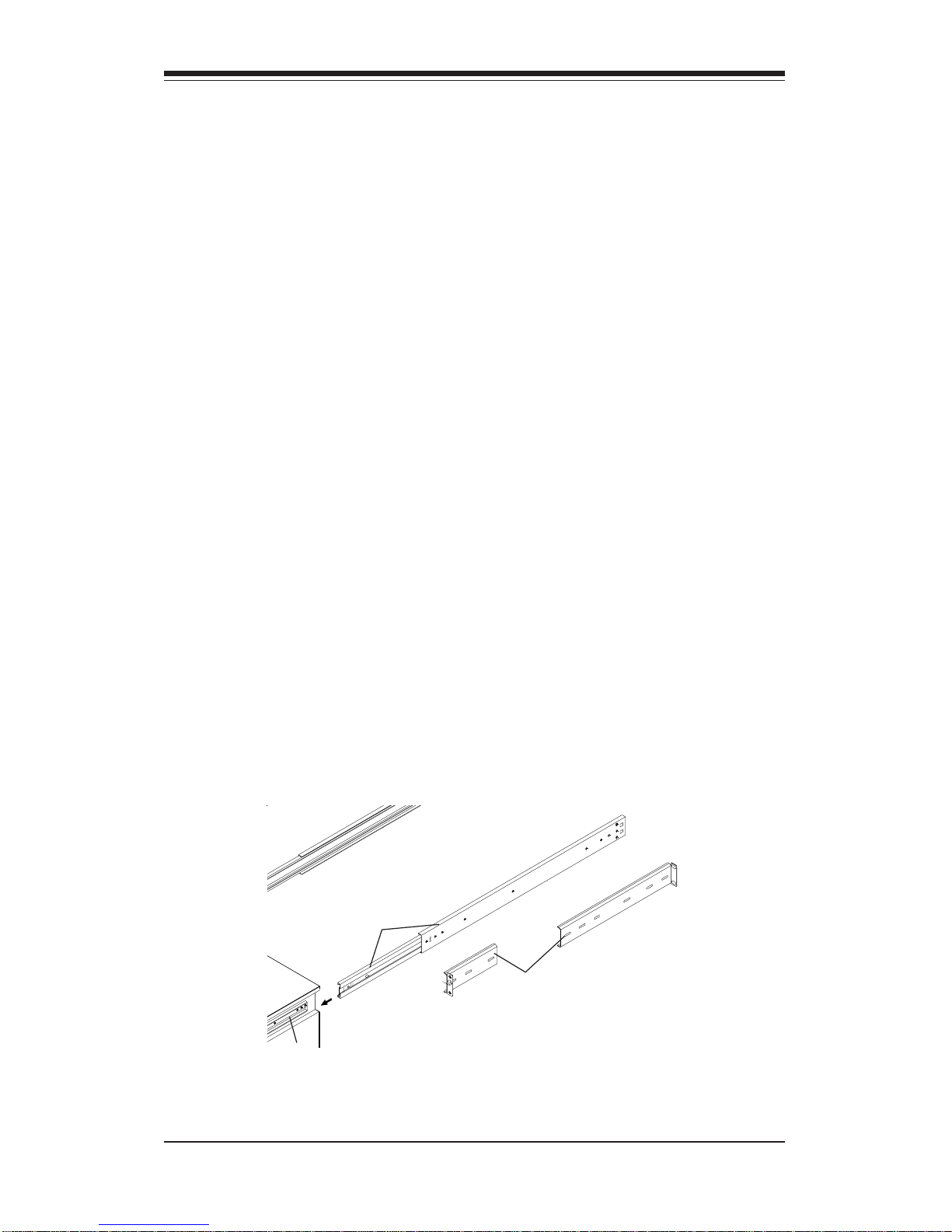
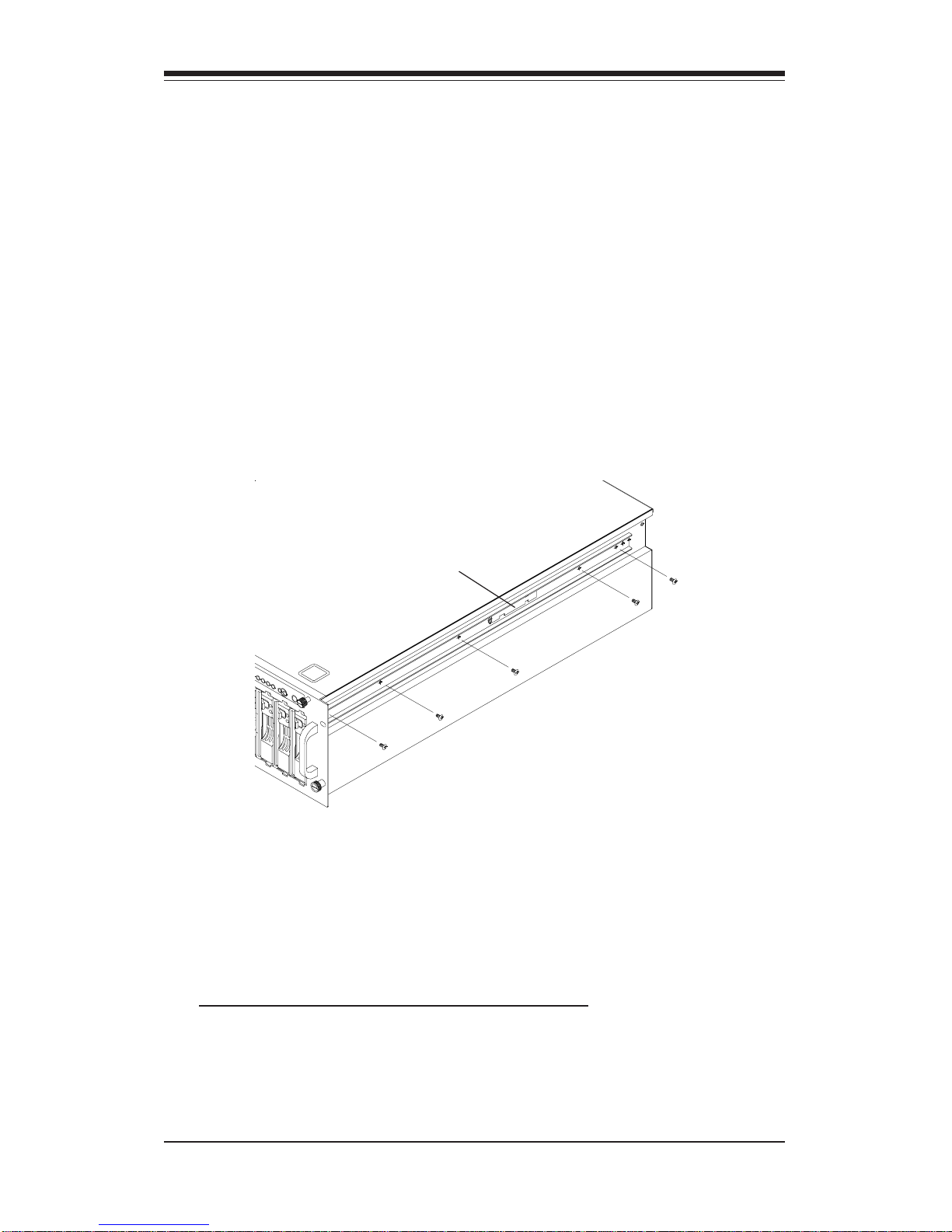
Identifying the Sections of the Rack Rails
You should have received two rack rail assemblies with the SuperServer
6041G. Each of these assemblies consist of three sections: an inner fixed
chassis rail that secures to the 6041G (A), an outer fixed rack rail that
secures directly to the rack itself (B), and a sliding rail guide (C) between
the two, which should remain attached to the fixed rack rail. (See Figure 21, which shows the chassis rail 'A' already attached to the chassis).
The first thing you must do is to remove the fixed chassis rail (A)
from each assembly. To do this, pull this inner rail out as far as possible
- you should hear a "click" sound as a locking tab emerges from inside
the rail assembly and locks the inner rail. Depress the locking tab to pull
the inner rail completely out.
Figure 2-1. Identifying the Sections of the Rack Rails
A
C
B
Page 20
2-4
SUPERSERVER 6041G Manual
Installing the Chassis Rails
Position the fixed chassis rail sections you just removed along the side of
the 6041G chassis making sure the five screw holes line up. Be aware
that these two rails are left/right specific. Screw the rail securely to the
side of the chassis (see Figure 2-2). Repeat this procedure for the other
rail on the other side of the chassis.
Locking Tabs: As you have seen, both chassis rails have a locking tab,
which serves two functions. The first is to lock the server into place
when installed and pushed fully into the rack, which is its normal position.
These tabs also lock the server in place when fully extended from the
rack. This prevents the server from coming completely out of the rack
when you pull it out for servicing.
Figure 2-2. Installing the Chassis Rails
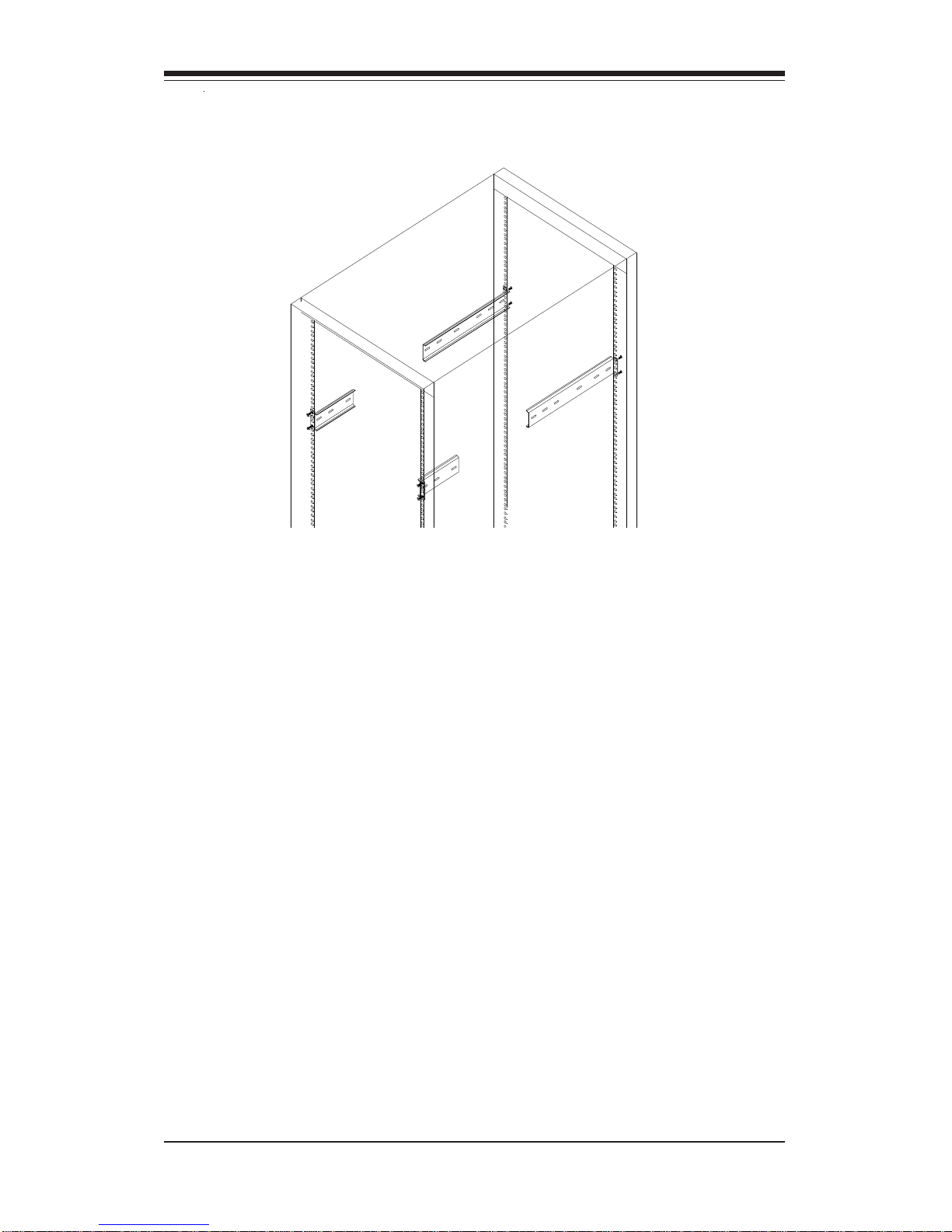
Installing the Rack Rails
Determine where you want to place the SuperServer 6041G in the rack.
(See Rack and Server Precautions in Section 2-3.) Position the fixed rack
rail/sliding rail guide assemblies at the desired location in the rack,
keeping the sliding rail guide facing the inside of the rack. Screw the
assembly securely to the rack using the brackets provided. Attach the
other assembly to the other side of the rack, making both are at the exact
same height and with the rail guides facing inward (see Figure 2-3).
Locking Tab
Page 21
Chapter 2: Server Installation
2-5
Figure 2-3. Installing the Rack Rails
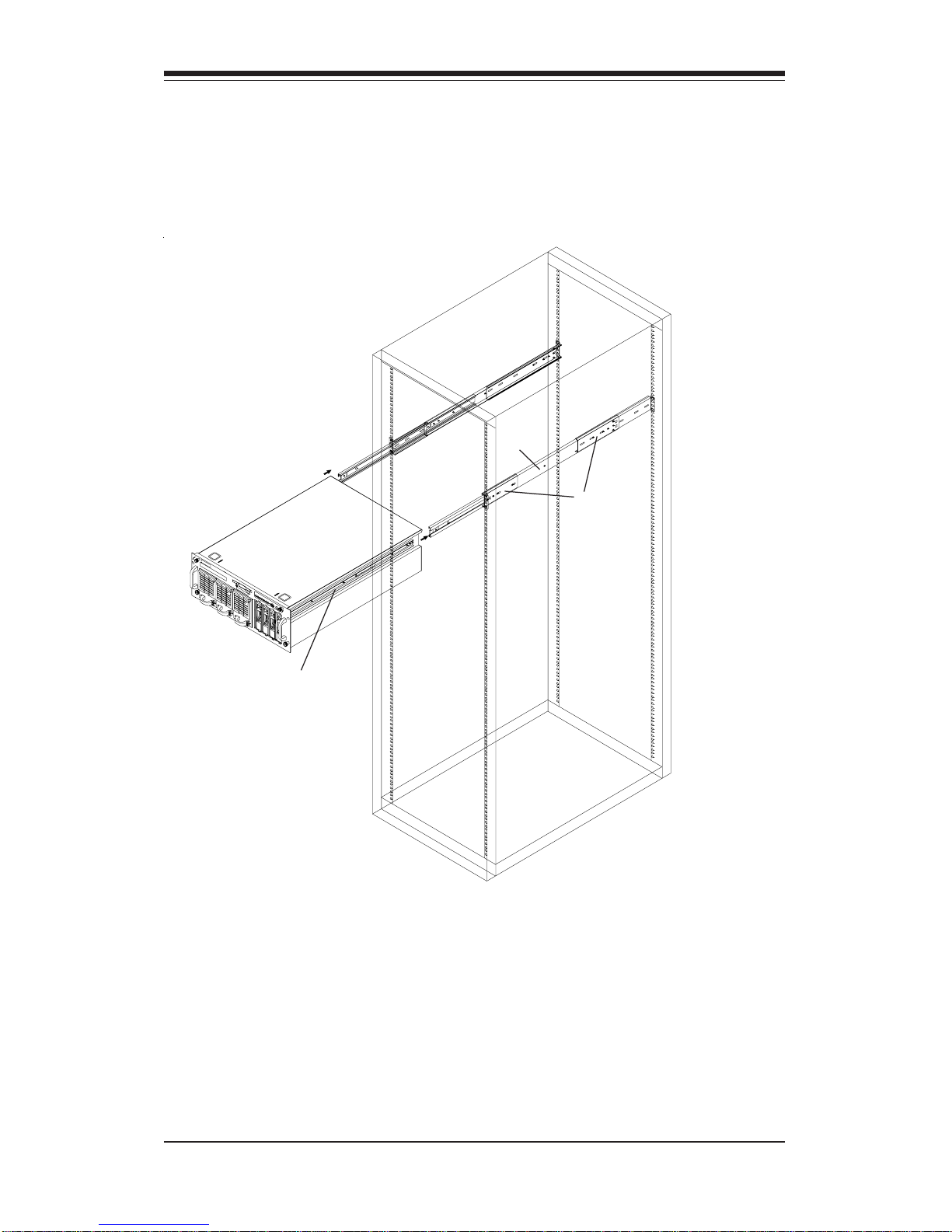
Installing the Server Into the Rack
You should now have rails attached to both the chassis and the rack
unit. The next step is to install the server into the chassis. Do this by
lining up the rear of the chassis rails with the front of the rack rails.
Slide the chassis rails into the rack rails, keeping the pressure even on
both sides (you may have to depress the locking tabs when inserting).
See Figure 2-4 on the next page.
When the server has been pushed completely into the rack, you should
hear the locking tabs "click". Finish by inserting and tightening the
thumbscrews that hold the front of the server to the rack.
*For best results, the rack cabinet depth should be 900 mm or more.
Page 22
2-6
SUPERSERVER 6041G Manual
Figure 2-4. Installing the Server Into the Rack
A
C
B
Page 23

Chapter 2: Server Installation
2-7
2-5 Checking the Motherboard Setup
After you install the 6041G in the rack, you will need to open the unit to
make sure the motherboard is properly installed and all the connections
have been made.
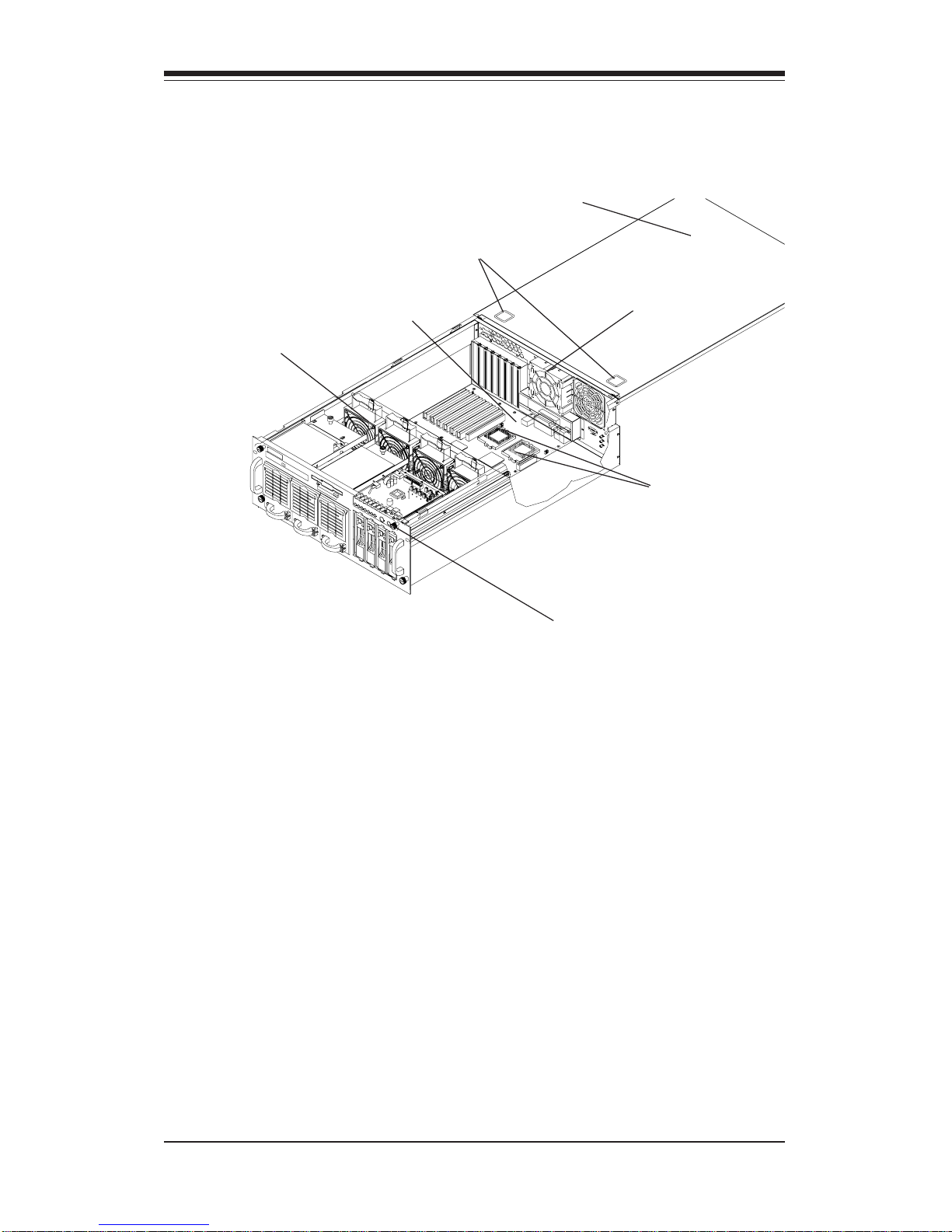
1. Access the inside of the 6041G (see Figure 2-5)
First, release the retention screws that secure the unit to the rack.
Next, release the two thumbscrews that secure the top cover to the
chassis. Grasp the two handles on either side and pull the unit
straight out until it locks (you will hear a "click"). There are two
square recesses in the top cover to help you push the cover away
from you until it stops. You can then lift the top cover from the
chassis. You now have full access to the inside of the server.
2. Check the CPUs (processors)
You should have one or two processors fully inserted into the system
board. If one CPU is used, install the CPU into CPU Socket 1 (see
Chapter 5). Inadequte ventilation or improper installation of the CPU
heat sinks may result in the instability of the system. When installing
the heat sinks, use the proper type of thermal glue and apply the
proper amount of thermal glue on the die of the CPU. improper type or
amount of thermal glue used on the die of the CPU and improper
installation of the heat sink may result in the crash of the system.
3. Verify the proper CPU core/bus ratio setting
You need to verify that the CPU core/bus ratio as set with DIP Switch
1 matches the speed of your installed processors. This DIP Switch is
defaulted to 5.5, which corresponds to 550 MHz processors running
on a 100 MHz front side bus (FSB). If the setting is different or if you
are using processors of a different speed, you may need to change
this setting.
4. Check all cable connections and airflow
Make sure all power and data cables are properly and firmly connected
and not blocking the airflow.
Page 24
2-8
SUPERSERVER 6041G Manual
Figure 2-5. Accessing the Inside of the SuperServer 6041G
Exhaust Fan
Control Panel
PCB
Processors
Cooling Fans
Top Chassis Cover (Removed)
P3TDE6
Motherboard
Cover Recesses
Page 25

Chapter 2: Server Installation
2-9
2-6 Checking the Drive Bay Setup
Next, you should check to make sure the peripheral drives and the SCA
drives and backplane have been properly installed and all connections have
been made.
1. Accessing the drive bays
All drives can be accessed from the front of the server. For servicing
the CD-ROM and floppy drives, you will need to remove the top
chassis cover. The SCSI disk drives can be installed and removed
from the front of the chassis without removing the top chassis cover.
2. Install a CD-ROM and floppy disk drives
Refer to Section 6-4 if you need to reinstall a CD-ROM and/or floppy
disk drive to the system.
3. Check the SCSI disk drives
Depending upon your system's configuration, your system may have
some SCSI drives already installed. If you need to install SCSI drives,
please refer to Section 6-4.
4. Check the airflow
Airflow is provided by four hot-swap input fans and one exhaust fan,
all of which are 9-cm in size. An air shroud has been installed to
direct sufficient cooling air to the processors, which generate the most
heat. Also note that all power and data cables have been routed in
such a way that they do not block the airflow generated by the fans.
5. Supply power to the system
The last thing you must do is supply power to the system. Plug two or
all three power cords from the two power supply units into a highquality power strip that offers protection from electrical noise and
power surges. It is recommended that you use an uninterruptible
power supply (UPS).
Page 26

2-10
SUPERSERVER 6041G Manual
Notes
Page 27

Chapter 3: System Interface
3-1
Chapter 3
System Interface
3-1 Overview
There are several LEDs on the control panel as well as others on the power
supply units, the SCSI drive carriers and the motherboard to keep you constantly informed of the overall status of the system as well as the activity
and health of specific components. There are also three switches that
allow you to take action based on the information provided by these LEDs.
This chapter explains the meanings of all LED indicators and audible alarms
and the appropriate response you may need to take.
3-2 Control Panel Switches
There are three push-button switches located on the front of the chassis.
These are (in order from left to right) a power on/off switch, an alarm
disable switch and a reset switch.
z POWER: This is the main power switch, which is used to apply or
turn off the power supplied to the power supply units on the 6041G.
z ALARM: Depressing the alarm switch will disable the audible alarm,
which is generated to notify you of chassis overheating or a fan/power
supply failure. The LED indicating the cause of the alarm will remain illuminated after the audible alarm is disabled.
z RESET: The reset switch reboots the system.
ALARM
RESET
Page 28
SUPERSERVER 6041G Manual
3-2
3-3 Control Panel LEDs
The control panel located on the front of the SC840 chassis has seven
LEDs. These LEDs provide you with critical information related to different
parts of the system. This section explains what each LED indicates when
illuminated and any corrective action you may need to take.
z Power: Indicates power is being supplied to the system's power
supply units. This LED should normally be illuminated when the system is
operating.
z NIC: Indicates network activity on the system when flashing.
z HDD: Indicates IDE channel activity. On the SuperServer 6041G, this
light indicates CD-ROM drive activity when flashing.
z PWR Fault: Indicates a power supply failure. This should be accom-
panied by an audible alarm, which you can disable with the alarm switch on
the control panel. Inspect the power supply units at the front left of the
chassis. The unit with the red LED illuminated has failed. Refer to Section
6-5 for instructions on replacing the failed unit. Because the power sup-
Page 29
Chapter 3: System Interface
3-3
plies are hot-plug units, you do not need to remove power from the system
when replacing. (The third power supply unit is a backup that activates
automatically to keep power supplied to the system.)
z Fan Fail: Indicates a system fan failure. This may be one or more of
the four hot-swap intake fans or the one exhaust fan. A fan failure is
accompanied by an audible alarm, which you can disable with the alarm
switch on the control panel. When a fan stops working, all the other system fans will increase their RPM to compensate until the failed unit is replaced. (See Section 6-2 for more details.) Refer to Section 6-3 for instructions on replacing system fans. It is unnecessary to power down the
system as these are hot-swap fans. Note: You must use the exact same
brand and rating of fan for replacement. These can be obtained directly
from Supermicro.
z Overheat: Indicates an overheat condition in the chassis. This may
be caused by cables obstructing the airflow in the system, or the ambient
room temperature being too warm. You should also check to make sure
that the chassis cover is installed and that all fans are present and operating normally.
z SCA Channel: Indicates an overheat condition in the area of the SCA
SCSI drives and backplane. This may be caused by cables obstructing the
airflow in the system, or the ambient room temperature being too warm.
You should also check to make sure that the chassis cover is installed and
that all fans are present and operating normally.
Page 30

SUPERSERVER 6041G Manual
3-4
3-4 SCSI Drive Carrier LEDs
Each SCSI drive carrier has two LEDs.
z Green: When illuminated, the green LED on the front of the SCSI drive
carrier indicates drive activity. A connection to the SCSI SCA backplane
enables this LED to blink on and off when that particular drive is being
accessed.
z Red: When illuminated, the red LED on the front of the SCSI drive
carrier indicates the drive has experienced a fault or has crashed. Please
refer to Section 6-4 for instructions on replacing failed SCSI drives.
3-5 Power Supply LEDs
Each of the two separate power units that comprise the power supply has
a single LED that can be illuminated either as green or red.
z Green: When green, the power unit has power applied to it and is
operating normally.
z Red: A red LED is normal only when system power has been turned
off. If the LED is red, it indicates that either (1) no power is being applied
to that particular power unit or (2) that particular power unit has failed.
First check to make sure the power cord for that unit is plugged into both
the power unit and a grounded wall outlet/power strip. If the power cord is
properly connected, not, refer to Section 6-5 for instructions on replacing
the power supply unit.
3-6 Motherboard LED
There is only one LED on the motherboard. When illuminated, it indicates
that system power is present on the motherboard. This LED is located at
the lower right hand corner of the P3TDE6 when installed in and viewed
from the front of the rackmount chassis. This LED provides the same
indication as the Power LED on the control panel.
Page 31

Chapter 4: System Safety
4-1
Chapter 4
System Safety
4-1 Electrical Safety Precautions
!
Basic electrical safety precautions should be followed to protect
yourself from harm and the SuperServer6041G from damage:
z Be aware of the locations of the power on/off switch on the chassis
as well as the room's emergency power-off switch, disconnection
switch or electrical outlet. If an electrical accident occurs, you can
then quickly remove power from the system.
z Do not work alone when working with high voltage components.
z Power should always be disconnected from the system when removing
or installing main system components, such as the motherboard,
memory modules and IDE and floppy drives. When disconnecting
power, you should first power down the system with the operating
system first and then unplug the power cords of all the power supply
units in the system.
z When working around exposed electrical circuits, another person who
is familiar with the power-off controls should be nearby to switch off
the power if necessary.
z Use only one hand when working with powered-on electrical
equipment. This is to avoid making a complete circuit, which will
cause electrical shock. Use extreme caution when using metal tools,
which can easily damage any electrical components or circuit boards
they come into contact with.
z Do not use mats designed to decrease static electrical discharge as
protection from electrical shock. Instead, use rubber mats that have
been specifically designed as electrical insulators.
z The power supply power cords must include a grounding plug and must
be plugged into grounded electrical outlets.
Page 32

SUPERSERVER 6041G Manual
4-2
4-2 General Safety Precautions
Follow these rules to ensure general safety:
z Keep the area around the SuperServer 6041G clean and free of clutter.
z The SuperServer 6041G weighs approx. 67 lbs. (30.5 kg.) when fully
loaded. When lifting the system, two people at either end should lift
slowly with their feet spread out to distribute the weight. Always
keep your back straight and lift with your legs.
z Place the chassis top cover any system components that have been
removed away from the system or on a table so that they won't
accidentally be stepped on.
z While working on the system, do not wear loose clothing such as
neckties and unbuttoned shirt sleeves, which can come into contact
with electrical circuits or be pulled into the one of the cooling fans.
z Remove any jewelry or metal objects from your body, which are
excellent metal conductors that can create short circuits and harm you
if they come into contact with printed circuit boards or areas where
power is present.
z After accessing the inside of the system, close the system back up
and secure it to the rack unit with the retention screws after ensuring
that all connections have been made.
!
z Motherboard Battery: CAUTION - There is a danger of explosion if the
onboard battery (located near the DIMM modules) is installed upside
down, which will reverse its polarity (see Figure 4-1). This battery
must be replaced only with the same or an equivalent type
recommended by the manufacturer. Dispose of used batteries
according to the manufacturer's instructions.
z CD-ROM Laser: CAUTION - this server may have come equipped with
a CD-ROM drive. To prevent direct exposure to the laser beam and
hazardous radiation exposure, do not open the enclosure or use the
unit in any unconventional way.
Page 33

Chapter 4: System Safety
4-3
4-3 ESD Precautions
Electrostatic discharge (ESD) is generated by two objects with different
electrical charges coming into contact with each other. An electrical
discharge is created to neutralize this difference, which can damage
electronic components and printed circuit boards. The following
measures are generally sufficient to neutralize this difference before
contact is made to protect your equipment from ESD:
z Use a grounded wrist strap designed to prevent static discharge.
z Keep all components and printed circuit boards (PCBs) in their
antistatic bags until ready for use.
z Touch a grounded metal object before removing the board from the
antistatic bag.
z Do not let components or PCBs come into contact with your clothing,
which may retain a charge even if you are wearing a wrist strap.
z Handle a board by its edges only; do not touch its components,
peripheral chips, memory modules or contacts.
z When handling chips or modules, avoid touching their pins.
z Put the motherboard and peripherals back into their antistatic bags
when not in use.
z For grounding purposes, make sure your computer chassis provides
excellent conductivity between the power supply, the case, the mounting
fasteners and the motherboard.
!
Page 34

SUPERSERVER 6041G Manual
4-4
4-4 Operating Precautions
Care must be taken to assure that the chassis cover is in place when
the 6041G is operating to assure proper cooling. Out of warranty
damage to the 6041G system can occur if this practice is not strictly
followed.
!
Figure 4-1. Installing the Onboard Battery
LITHIUM BATTERY
BATTERY HOLDER BATTERY HOLDER
LITHIUM BATTERY
OR
Page 35

Chapter 5: Advanced Motherboard Setup
5-1
Chapter 5
Advanced Motherboard Setup
This chapter covers the steps required to install the P3TDE6 motherboard
into the SC840 chassis, connect the data and power cables and install addon cards. All motherboard jumpers and connections are also described. A
layout and quick reference chart are on pages 5-10 and 5-11. Remember to
completely close the chassis when you have finished working with the
motherboard to better cool and protect the system.
Tools Required
The only tools you will need to install the P3TDE6 into the chassis are
a long and a short Philips screwdriver.
5-1 Handling the P3TDE6 Motherboard
Static electrical discharge can damage electronic components. To prevent
damage to any printed circuit boards (PCBs), it is important to handle them
very carefully (see previous chapter). Also note that the size and weight
of the P3TDE6 motherboard can cause it to bend if handled improperly,
which may result in damage. To prevent the P3TDE6 motherboard from
bending, keep one hand under the center of the board to support it when
handling. The following measures are generally sufficient to protect your
equipment from static discharge.
Precautions
• Use a grounded wrist strap designed to prevent static discharge.
• Touch a grounded metal object before removing any board from its anti-
static bag.
• Handle a board by its edges only; do not touch its components, periph-
eral chips, memory modules or gold contacts.
• When handling chips or modules, avoid touching their pins.
• Put the motherboard, add-on cards and peripherals back into their anti-
static bags when not in use.
Page 36

5-2
SUPERSERVER 6041G Manual
5-2 Motherboard Installation
This section explains the first step of physically mounting the P3TDE6 into
the SC840 chassis. Following the steps in the order given will eliminate the
most common problems encountered in such an installation. To remove the
motherboard, follow the procedure in reverse order.
1. Access the inside of the 6041G (see Figure 2-5)
First, release the two retention screws that secure the unit to the
rack. Grasp the two handles on either side and pull the unit straight
out. Next, release the two screws that secure the top cover to the
chassis. Remove the top chassis cover by pushing forward on the
cover recesses until it stops. Lift the cover from the chassis. You
should now have full access to the inside of the server.
2. Install metal standoffs
With the chassis opened up, the motherboard tray is directly in front
of you. First, check that the location of all the mounting holes on
both the motherboard and the tray match. Refer to Figure 5-1 for
mounting hole locations. Attach metal standoffs to the mounting holes
(as marked #1-13 on Figure 5-1) on the motherboard tray. Make
sure these metal standoffs either click in or are screwed in tightly.
Several square rubber "feet" may be applied to the motherboard tray
to function as shock absorbers. Attach these feet to the small
square outlines on the tray.
3. Check compatibility of motherboard ports and I/O shield
The P3TDE6 requires a chassis big enough to support a 12" x 13"
motherboard, such as Supermicro's SC840 4U rackmount. Make sure
that the I/O ports on the motherboard properly align with their
respective holes in the I/O shield at the back of the chassis.
• For grounding purposes, make sure your computer chassis provides ex-
cellent conductivity between the power supply, the case, the mounting
fasteners and the motherboard.
Unpacking
The motherboard is shipped in antistatic packaging to avoid static electrical
damage. When unpacking the board, make sure the person handling it is
static protected.
Page 37

Chapter 5: Advanced Motherboard Setup
5-3
Figure 5-1. Mounting Holes on Motherboard (top view)
Number of motherboard mounting holes: 13
4. Mount the motherboard onto the motherboard tray
Carefully mount the motherboard to the motherboard tray by aligning
the board holes with the metal standoffs you just installed. Insert
screws into all the mounting holes provided and tighten until snug.
Note: To prevent the screw heads from making direct contact with
the MB traces (which will create an electrical short) you may place
washers on top of the mounting holes before inserting screws into
the holes.
1
23
4
5
67
89
10
11
12
13
Page 38

5-4
SUPERSERVER 6041G Manual
5-3 Connecting Cables
Now that the motherboard is installed, the next step is to connect the cables
to the board. These include the data (ribbon) cables for the peripherals and
front control panel, the power fail signal (PWR P) cable and the power
cables.
Connecting Data Cables
The ribbon cables used to transfer data from the peripheral devices
have been carefully routed to prevent them from blocking the flow of
cooling air that moves through the system from front to back. If you
need to disconnect any of these cables, you should take care to keep
them routed as they were originally after reconnecting them (make
sure the red wires connect to the pin 1 locations). The following data
cables (with their locations noted) should be connected. (See the
layout on page 5-12 for connector locations.)
z IDE Device Cables (J13 and J14)
z Floppy Drive Cable (J15)
z SCSI Device Cables (JA2, JA4 and JP60)
z Control Panel Cable (JF1, see next page)
z Power Fail Signal Cable (PWR P)
Connecting Power Cables
The P3TDE6 has two primary power supply connectors: ATX Power #1
and ATX Power #2. You must connect both the primary and the secondary ATX power connectors to your power supply. See the layout
on page 5-12 for connector locations.
Page 39

Chapter 5: Advanced Motherboard Setup
5-5
Connecting the Control Panel
The JF2 header on the P3TDE6 contains header pins for various control
panel connectors. See Figure 5-2 for the locations of the power and
reaset buttons and LEDs for overheat, NIC1, NIC2, the IDE hard disk drive
and power. Note that even and odd numbered pins are on opposite
sides of the connector. All JF2 wires have been bundled into a single
ribbon cable to simplify the connection to the 840 chassis. Make sure
the red wire plugs into pin 1 as marked on the board. The other end
connects to the Control Panel PCB board, located just behind the system
status LEDs on the chassis. See Section 5-8 for details (and pin descriptions for JF1).
JF1 also contains pins for these and other functions. JF1 was designed
for use with other chassis and is not used in the SuperServer 6041G.
Figure 5-2. Control Panel Connectors
PW R _LED
Speaker
I
2
C
NIC
LED
JF1
Keyboard
Lock
IDE LE D
1
34
USB3
PWR_ON
Reset
Unused
Overheat
LED
Chassis
Int.
5V
Standby
2
33
Fan
Fail
Power
Fail
Alarm
Reset
Pow e r Bu tto n
JF2
Overheat LED
1
NIC1 LED
Res e t B u tton
2
Power Fail Button
X
HDD LED
Power LED
5V
5V
3V
3V
5V
Reset
Pwr
Control
Control
Control
Control
Control
Ground
Ground
1516
PFGround
Page 40

5-6
SUPERSERVER 6041G Manual
5-4 I/OPorts/Control Panel Connectors
The I/O ports are color coded in conformance with the PC 99 specification.
See Figure 5-3 below for the colors and locations of the various I/O ports.
Figure 5-3. I/O Port Locations and Definitions
Parallel Port
(Burgundy)
COM1 COM2
Keyboard
(Purple)
Mouse
(Green)
USB
Ports
LAN (Ethernet)
Port (Turquoise)
Page 41

Chapter 5: Advanced Motherboard Setup
5-7
5-5 Processor Installation
When handling the processor package, avoid
placing direct pressure on the label area of the fan.
This section covers the installation procedure for 370-pin socket processors. You should install the processor first and then install the motherboard in the chassis. Following the installation procedures in the order they
appear in this section should eliminate the most common problems encountered when installing a system.
IMPORTANT: Always connect the power cord last and always remove it
before adding, removing or changing any hardware components.
!
Heatsink
Follow the instructions that came with your processor or heatsink to attach
a heatsink to the processor. Your heatsink should have a 3-pin fan, which
connects to the CPU FAN header. Make sure that good contact is made
between the CPU chip (the die) and the heatsink. Insufficient contact or
improper types of heatsinks, thermal compound or fans can cause the processor to overheat, which may crash the system. (You can check the CPU
temperature readings in the "Periperal Setup" Section of BIOS.)
Processor
Your motherboard has two 370-pin sockets, which support Intel FCPGA
processors. Lift the lever on the socket and insert the processor with the
notched corner oriented toward pin one on the socket. Make sure the
processor is fully seated in the socket and and then close the lever. You
can also install a single 370-pin CPU in CPU Socket 1 without changing any
jumper settings. See Figure 5-3 for views of the 370-pin socket before and
after processor installation.
Mounting the Motherboard in the Chassis
All motherboards have standard mounting holes to fit different types of
chassis. Make sure the location of all the mounting holes for both the
motherboard and the chassis match. Although a chassis may have both
plastic and metal mounting fasteners, metal ones are highly recommended
because they ground the motherboard to the chassis. Make sure the metal
standoffs click in or are screwed in tightly. Then use a screwdriver to
secure the motherboard onto the motherboard tray.
Page 42

5-8
SUPERSERVER 6041G Manual
When removing a Pentium III 370-pin processor, avoid
pressing down on the motherboard or any of its components.
!
Removing Pentium III 370-pin Processors
To remove the Pentium III 370-pin processors from the motherboard, follow
the installation process in reverse order.
5-4 370-pin Socket: Empty and with Processor Installed
Page 43

Chapter 5: Advanced Motherboard Setup
5-9
5-6 Installing DIMMs
CAUTION
Exercise extreme care when installing or removing
DIMM modules to prevent any possible damage.
Also note that the memory is interleaved to improve
performance (see step 1).
DIMM Installation (See Figure 5-4)
1. Insert either two or four DIMMs as required for the desired system
memory. Two-way interleaved memory requires that memory modules be
installed in pairs (first in the two slots of Bank0 and then in both slots of
Bank if needed).
2. Insert each DIMM module vertically into its slot. Pay attention to the two
notches along the bottom of the module to prevent inserting the DIMM module incorrectly.
3. Gently press down on the DIMM module until it snaps into place in the
slot. Repeat for all modules (see step 1 above).
Support
The P3TDE6 only supports ECC registered SDRAM memory. PC133 and
PC100 memory are both supported at their respective speeds. However,
the memory speed is synchronized with CPU's front side bus speed.
Therefore, the FSB of the CPU will determine the memory speed.
Note: Notches
should align
with the
receptive points
on the slot
DIMM Slot
DIMM
PC100
Notches
PC100
Notches
To Install: Insert module vertically and press down
until it snaps into place. Pay attention to the notches.
Figure 5-5. DIMM Installation
!
Page 44

5-10
SUPERSERVER 6041G Manual
Top View of DIMM Slot
To Remove: Use your thumbs to gently push near the edge of
both ends of the module. This should release it from the slot.
5-7 Adding PCI Cards
1. 64-bit PCI slots:
The P3TDE6 has six 64-bit PCI slots. Two of these are 64-bit 66 MHz
slots that are keyed to only accept 66 MHz, 3.3V PCI cards. The other
four 64-bit, 5V PCI slots also support 3.3V and run at 33MHz. These four
slots are fully compatible with 32-bit PCI devices.
2. PCI card installation:
You are now ready to install your PCI add-on cards. Make sure you
choose the correct slot for the type of card you are installing (see Step
1). First, remove the I/O shield for the proper slot. Then fully seat the
card into the slot, pushing down with your thumbs evenly on both sides
of the card. Finish by using a screw to secure the top of the card shield
to the chassis. The I/O shields protect the motherboard and its components from EMI (electromagnetic interference)and aid in proper ventilation,
so make sure there is a shield covering each slot.
Figure 5-6. Adding PCI Cards
5V, 64-bit PCI Slots (4) 3.3V, 64-bit PCI Slots (2)
CPU Sockets
AGP Pro
Page 45

Chapter 5: Advanced Motherboard Setup
5-11
Notes
Page 46

5-12
SUPERSERVER 6041G Manual
Figure 5-7. SUPER P3TDE6 Layout
(not drawn to scale)
SUPER P3TDE6
USB
COM1
PS/2 KB/
MOUSE
BATTERY
J16
Parallel
Port
FLOPPY
13"
ATX POWER #1
CPU
FAN1
J18
®
CPU
1
CPU
FAN2
DIMM1 BANK0
PWR_SEC
IDE #1
IDE #2
JP1
J13
J14
ULTRA160 LVD SCSI CHA
JF1
JP3
WOR
CPU
2
JP62
3V/PCI64 #2
BIOS1
JP54
JP57
JA4
SLED
AIC-7899
SUPER
I/O
OH FAN
CHASSIS FAN
SW1
JP58
COM2
LAN
J19
J15
POWER LED
JBT1
JA6 JA2
JP60
JP61
JP56
JA1
1
JP59
ATX POWER #2
OH FAN
CHASSIS FAN
Ultra SCSI (Channel B)
ULTRA160 LVD SCSI CHB
JA3
JA5
1
AGP PRO
3V/PCI64 #1
5V/PCI64 #4
5V/PCI64 #3
5V/PCI64 #2
5V/PCI64 #1
1
JP55
Speaker
WOL
Note: Memory modules must be installed in pairs. Jumpers not indicated are
for test purposes only.
BIOS2
JP52
JP63
North
Bridge
South
Bridge
CIOB
DIMM1 BANK1
DIMM2 BANK0
DIMM2 BANK1
12"
Also see Figures 5-2 and 5-3 for the locations of the I/O ports and the Front
Control Panel (JF1) connectors. See Section 5-8 for details on jumper settings
and pin definitions.
Page 47

Chapter 5: Advanced Motherboard Setup
5-13
P3TDE6 Quick Reference
Jumper Description Default Setting
JA2 LVD SCSI Ch A Term. Open (Enabled)
JA4 LVD SCSI Ch B Term. Open (Enabled)
JA6 50pin SCSI Ch B Term Open (Enabled)
JBT1 CMOS Clear Pins 1-2 (Normal)
JP1 FSB Speed Setting Pins 1-2 (Auto)
JP3 Spread Spectrum Enable Open (Disabled)
JP55 Third P/S Fail Enable/Disable On (Enabled)
JP56 Speaker Enable/Disable On (Enabled)
JP57 BIOS Select Pins 1-2 (BIOS1)
JP58 LAN/NIC Enable/Disable Off (Enabled)
JP60 SCSI Enable/Disable Pins 1-2 (Enabled)
JP61 PCI 66/33 MHz Select On (33 MHz)
JP62 Thermal Fan Enable/Disable On (Enabled)
DIP Switch Description
SW1(1-4) CPU Core/Bus Ratio
Connector Description
ATX POWER #1 Primary ATX Power Connector
ATX POWER #2 Secondary ATX Power Connector
BANK0-BANK1 Memory (RAM) Slots
COM1/COM2 COM1/COM2 Serial Port Connector
CPU1/CPU2 CPU 1 and CPU2 Sockets
CPU/CH/OH FAN CPU/Chassis/Overheat Fan Headers
J13, J14 IDE Hard Disk Drive Connectors
J15 Floppy Disk Drive Connector
J16 Parallel Printer Port
J18 PS/2 Keyboard/Mouse Ports
JA1 Ultra160 LVD SCSI CH A Connector
JA3 Ultra160 LVD SCSI CH B Connector
JF1 Front Control Panel Connector
JP52 Chassis Intrusion Header
JP54 Third Power Supply Fail Header
JP63 NMI (Non-Maskable Interrupt) Header
LAN Ethernet Port
PWR_SEC Secondary ATX Power Connector
SLED1 SCSI Active LED header
USB Universal Serial Bus Ports
WOL Wake-on-LAN Header
WOR Wake-on-Ring Header
Page 48

5-14
SUPERSERVER 6041G Manual
5-8 Connector Definitions
Power Supply Connector
After you have mounted the motherboard and added memory and
PCI cards, you are ready to connect the cables. Attach an ATX
power supply cable to ATX #1.
See the table on the right for the
pin definitions of these ATX power
supply connectors.
Secondary Power Connector
Use of the secondary power connector at J19 is recommended
when a heavy load of peripherals
has been added to the motherboard. See the table at right for
pin definitions. Note: Be sure to use a 6-
pin connector and check the power supply layout before making the connection.
Second ary Pow e r Conne cto r
(J19)
Pin
Number Definition
1 G round
2 G round
3 G round
4 +3.3V
5 +3.3V
6 +5 V ( ke y e d )
ATX Power Supply Connector
Pin Definitions
Pin Number Definition
1 3.3V
2 3.3V 3
3 Ground
4 5V
5 Ground
6 5V
7 Ground
8 PW - O K
9 5V S B
10 12V
Pin Number Definition
11 3.3V
12 -12V
13 Ground
14 PS- O N
15 Ground
16 Ground
17 Ground
18 -5V
19 5V
20 5V
Power Button
The Power Button connection is
located on pins 1 and 2 of JF2.
Momentarily contacting both pins
will power on/off the system. The
user can also configure this button to function as a suspend button (see the Power Button Mode
setting in BIOS). To turn off the
power when set to suspend mode,
hold down the power button for at
least 4 seconds. See Figure 5-2
for pin definitions. See the table
on the right for pin definitions on
JF1 (PWR_ON).
Pin
Number
11
13
Defin i ti o n
PW _ON
Ground
PWR _O N Co nne ctor
Pin Definitions
(JF1)
Page 49

Chapter 5: Advanced Motherboard Setup
5-15
Reset
The Reset connection is located
on pins 3 and 4 of JF2. This connector attaches to the hardware
reset switch on the computer
case. See Figure 5-2 for pin definitions. See the table on the right
for pin definitions on JF1.
Pin
Number
15
17
Defin i tio n
Reset
Ground
Reset Pin
Definitions
(JF1 )
NIC 1 LED
The LED connection for the Network Interface Controller 1 is located on pins 11 and 12 of JF2.
This header is used to display network activity for LAN1. See Figure 5-2 for pin definitions. See the
table on the right for pin definitions
on JF1.
NIC LED Pin
Definition s
(JF1 )
Pin
Number
12
14
Defin i tio n
+5V
GND
Power Fail LED (PFL)
The Power Fail LED connection is
located on pins 5 and 6 of JF2.
See Figure 5-2 for pin definitions.
See the table on the right for pin
definitions on JF1.
Pin
Number
8
10
Defin i ti o n
+5V
PW R Fail
Power Fail LED
Pin Definitions
(JF1)
Overheat LED (OH)
Pins 7 and 8 on JF2 are for the
overheat LED, which provides advance warning of chassis overheating. See Figure 5-2 for pin
definitions. See the table on the
right for pin definitions on JF1.
Overheat LED (OH)
Pin Definitions
(JF1 )
Pin
Number
26
Defin i tio n
OH A cti ve
Page 50

5-16
SUPERSERVER 6041G Manual
I2C
The I2C connection is located on
pins 16 and 18 of JF1. Refer to
the table on the right for pin definitions.
I2C Pin Definitions
(JF1 )
Pin
Number
16
18
Defin i tio n
SDA
SCL
Chassis Intrusion
A Chassis Intrusion connection is
located on pin 20 of JF1. See the
table on the right for pin definitions. Note: An extra chassis intrusion header is provided at JP52.
Pin
Number
20
Defin itio n
Intrusion Input
Chassis Intrusion
Pin Definitions (JF1)
HDD (IDE) LED
The IDE hard drive LED connection
is located on pins 13 and 14 of
JF2. See Figure 5-2 for pin definitions. See the table on the right
for pin definitions on JF1.
IDE LED Pin
Definition s
(JF1 )
Pin
Number
7
9
Defin i tio n
+5V
HD Active
Power LED
The Power LED connection is located on pins 15 and 16 of JF2.
See Figure 5-2 for pin definitions.
See the table on the right for pin
definitions on JF1.
Pin
Number
1
3
5
Defin itio n
+5V
Key
GND
PWR_LED Pin Definitions
(JF1)
Fan Fail
The Fan Fail LED connnection is
located on pins 4 and 6 of JF1.
Refer to the table on the right for
pin definitions.
Pin
Number
4
6
Defin i ti o n
+5V
Fan Fail
Fan Fail LED
Pin Definitions
(JF1)
Page 51

Chapter 5: Advanced Motherboard Setup
5-17
Fan Header Pin Definitions
(CPU, CHASSIS and OH FAN)
Pin
Number
1
2
3
Defin i tion
Ground (black)
+12V (red)
Tachometer
Caution: These fan headers
are DC power.
Fan Headers*
There are several fan headers on
the P3TDE6 to provide cooling for
various components. In addition to
one fan header for each processor, there is one overheat and two
chassis fan headers. See the
motherboard layout for locations.
Refer to the table on the right for
pin definitions.
Note: The maximum current limitation for the onboard fans is 0.35
amps for each, not to exceed 1.2
amps for any group of four fans.
Speaker
The speaker connection is located
on pins 28, 30, 32 and 34 of JF1.
Refer to the table on the right for
pin definitions.
Speaker Connector Pin
Definition s (JF 1 )
Pin
Number
28
30
32
34
Function
"+"
Key
"-"
Defin i tio n
Red wire, Speaker PWR
No connection
Key
Speaker data
Keyboard Lock
The Keyboard Lock connection is
located on pins 22 and 24 of JF1.
Refer to the table on the right for
pin definitions.
Keyboard Lock
Pin Definitions
(JF1 )
Pin
Number
22
24
Defin i tio n
+5V
GND
USB3
An additional connection for USB3
is included on pins 25, 27, 29 and
31 of JF1 for front side USB access. You will need a USB cable
(not included) to use this connection. Refer to the table on the right
for pin definitions.
Pin
Number
25
27
29
31
Defin i tio n
Power
-
+
Ground
USB3 Pin
Definition s (J F 1 )
Page 52

5-18
SUPERSERVER 6041G Manual
Pin
Number
1
2
3
Defin itio n
+5V Standby
Ground
Wake-up
Wake-on-LAN
Pin Definitions (WOL)
Wake-On-LAN
The Wake-On-LAN header is designated as WOL. Refer to the
table on the right for pin definitions. You must enable the LAN
Wake-Up setting in BIOS to use
this feature. You must also have
a LAN card with a Wake-on-LAN
connector and cable.
ATX PS/2 Keyboard and
PS/2 Mouse Ports
The ATX PS/2 keyboard and the
PS/2 mouse are located on J18.
Refer to the table on the right for
pin definitions. (The mouse port is
above the keyboard port. See Figure 5-7.)
PS/2 Keyboard
and Mouse Port
Pin Definitions
(J18)
Pin
Number
1
2
3
4
5
6
Defin itio n
Data
*NC
Ground
VCC
Clock
*NC
Note: "NC" indicates "No connection".
Universal Serial Bus (USB)
Two Universal Serial Bus connectors are located beside the keyboard/mouse ports. USB0 is the
bottom connector and USB1 is the
top connector.
Ethernet Port
An Ethernet port is located beside
the VGA port on the I/O backplane.
This port accepts RJ45 type
cables. Two LEDs indicate a successful connection (yellow) and
activity (green).
RJ45 Ethernet Port
USB0/USB1 Ports
Page 53

Chapter 5: Advanced Motherboard Setup
5-19
SLED1 (SCSI LED) Indicator
The SLED connector is used to provide an LED indication of SCSI activity. Refer to the table on the right
for connecting the SCSI LED.
Pin
Number
1
2
3
4
Defin i tion
Positive
Negative
Negative
Positive
SCSI LED Pin Definitions
(SLED 1)
Wake-On-Ring
The Wake-On-Ring header is designated as WOR. Refer to the
table on the right for pin definitions. You must enable the Ring
Wake-Up setting in BIOS to use
this feature. You must also have
a modem card with a WOR connector and cable to use this feature.
Pin
Number
1
2
Definition
Ground
Wake-up
Wake-On-Ring
Pin Definitions
(WO R)
Chassis Intrusion
A 2-pin Chassis Intrusion header
is located at JP52. When a chassis intrusion microswitch is connected to JP52 a message will be
sent to the system administrator if
a chassis intrusion condition is
detected (activated when the top
cover of the chassis is removed).
See the table on the right for pin
definitions.
Pin
Number
1
2
Definition
Signal
Ground
Chassis Intrusion
Header
Pin Definitions
(JP52)
I2C Header
The I2C header is located at JP70.
See the table on the right for pin
definitions.
Pin
Number
1
2
Definition
SDA
SCL
I
2
C Header
Pin Definitions
(JP70)
Page 54

5-20
SUPERSERVER 6041G Manual
5-9 DIP Switch Settings
DIP Switch 1:
Core/Bus Ratio
The red "DIP" Switch labeled SW1
is located on the P3TDE6. SW1
has four individual switches
which are used to set the core/
bus ration. The table on the right
will show you which CPU Core/
Bus Ratio to use. The general rule
is to divide the CPU speed by the
bus speed (133 or 100 MHz for the
P3TDE6). For example, if you
have a 550 MHz CPU, dividing it by
100 will give you a CPU Core/BUS
Ratio of 5.5. After determining the
CPU Core/Bus Ratio, refer to the
table on the right for the correct
settings of DIP SW 1.
Note: Most Intel Processors
have a fixed Core/Bus ratio
that will overwrite the setting
of DIP Switch 1.
550 MHz = 100 MHz x 5.5
CPU Speed = Bus Freq. x Ratio
SW 1
#2
ON
ON
OFF
OFF
ON
ON
OFF
OFF
ON
ON
OFF
CPU
400-533
450-600
500-666
550-733
600-800
650-866
700-933
750-1000
800-1064
850-1130
900-1200
SW 1
#4
ON
ON
ON
ON
OFF
OFF
OFF
OFF
OFF
OFF
OFF
SW 1
#3
OFF
OFF
OFF
OFF
ON
ON
ON
ON
OFF
OFF
OFF
SW 1
#1
ON
OFF
ON
OFF
ON
OFF
ON
OFF
ON
OFF
ON
CPU Core/Bus Ratio Selection
(DIP Sw itch1)
Serial Ports
Serial ports COM1 and COM2 are
located under the parallel port (see
Figure 5-3). Refer to the table on
the right for pin definitions.
Serial Po rt Pin Definitions
(COM 1 , C O M 2 )
Pin Number Definition
1 DCD
2 DSR
3 Seria l In
4 RT S
5 Seria l Out
Pin Number Definition
6 CT S
7 DTR
8 RI
9 Ground
10 *NC
Page 55

Chapter 5: Advanced Motherboard Setup
5-21
Front Side Bus Speed
The JP1 jumper sets the FSB
speed. Refer to the table on the
right for a description of the
jumper settings.
5-10 Jumper Settings
Explanation of
Jumpers
To modify the operation of the
motherboard, jumpers can be used
to choose between optional settings. Jumpers create shorts between two pins to change the
function of the connector. Pin 1 is
identified with a square solder pad
on the printed circuit board. See
the motherboard layout pages for
jumper locations. Note: On a 2pin jumper, "Closed" means the
jumper is over both pins and
"Open" means the jumper is either
on one pin only or completely off.
Connector
Pins
Jumper
Cap
Setting
Pin 1-2 short
3 2 1
3 2 1
CMOS Clear
Refer to the table on the right for the
jumper settings to clear CMOS. Always
remove the AC power cord from the system before clearing CMOS.
NOTE: For an ATX power supply, you
must completely shut down the
system, remove the AC power cord
and then use JBT1 to clear CMOS.
Replace JBT1 back to the pin 1-2 position before powering up the system again. Do not use the PW_ON
connector to clear CMOS.
CMOS Clear Jumper Settings
(JBT 1)
Jumper
Positio n
1-2
2-3
Definition
Normal
CMOS Clear
Position
1-2
Position
2-3
Normal
CMOS Clear
Front Side Bus Speed Jumper
Settings (JP 1 )
Jumper
Position
1-2
2-3
OFF
Defin i tion
Auto
100 MHz
133 MHz
Note : The A u to s e ttin g a l lo w s
the CPU to set the speed .
Page 56

5-22
SUPERSERVER 6041G Manual
LVD Channel A SCSI
Termination Enable/
Disable
Jumper JA2 allows you to enable
or disable termination for the LVD
Channel A SCSI connector. The
normal (default) position is open to
enable SCSI termination. Refer to
the table on the right for jumper
settings.
Jumper
Position
Open
Closed
Defin itio n
Enabled
Disabled
LVD CH A SCSI
Te rm ina t io n
Jumper Settings (JA2)
LVD Channel B SCSI
Termination Enable/
Disable
Jumper JA4 allows you to enable
or disable termination for the LVD
Channel B SCSI connector. The
normal (default) position is open to
enable SCSI termination. Refer to
the table on the right for jumper
settings.
Jumper
Position
Open
Closed
Defin itio n
Enabled
Disabled
LVD CH B SCSI
Te rm ina t io n
Jumper Settings (JA4)
SCSI Termination Enable/
Disable
The SCSI Termination jumper
(JP64) allows you to enable or
disable termination for the SCSI
connectors. The normal (default)
position is open to enable SCSI
termination. Refer to the table on
the right for jumper settings.
SpeakerEnable/Disable
You may want to disable the
onboard speaker. Jumper JP56
gives you this option. Refer to the
table on the right for jumper settings.
Jumper
Position
Open
Closed
Defin itio n
Enabled
Disabled
SCS I T e rm in a tion
Enable/Dis a b le
Jump e r Setting s
(JP64)
Jumper
Position
Open
Closed
Defin itio n
Disabled
Enabled
Speaker Enable/Disable
Jumper Settings (JP56)
Page 57

Chapter 5: Advanced Motherboard Setup
5-23
LAN1 Enable/Disable
Use jumper JP58 to enable or disable LAN1/NIC (Network Interface
Card) on your motherboard. Refer
to the table on the right for jumper
settings.
Jumper
Position
Open
Closed
Defin itio n
Enabled
Disabled
LAN1/NIC
Enable/Dis a b le
Jumper Settings (JP58)
Thermal Fan Enable/
Disable
Use jumper JP65 to enable or disable the thermal fan. When enabled, the Thermal Fan will activate when the chassis temperature reaches a predetermined temperature. Refer to the table on the
right for jumper settings.
Jumper
Position
Open
Closed
Defin itio n
Disabled
Enabled
The rmal Fa n
Enable/Dis a b le
Jumper Settings (JP65)
PCI Speed Setting
Use jumper JP66 to set the speed
of the PCI slot. Refer to the table
on the right for jumper settings.
Jumper
Position
Open
Closed
Defin itio n
66 MHz
33 MHz
PCI Slot Speed
Jumper Settings (JP66)
VGA Enable/Disable
Use jumper JP68 to enable or disable the VGA port. Refer to the
table on the right for jumper settings.
Jumper
Position
Open
Closed
Defin itio n
VGA E n a b le/Disab le
Jumper Settings (JP68)
Page 58

5-24
SUPERSERVER 6041G Manual
Parallel Port Connector
The parallel port is located on J16
and requires a 26-pin ribbon cable
for operation. See the table on the
left for pin definitions.
Floppy Connector
The floppy connector is located
on J15 and requires a 34-pin ribbon cable for operation. See the
table on the right for pin definitions.
Pin Number Function
1 Strobe 3 Da ta B it 0
5 Da ta B it 1
7 Da ta B it 2
9 Da ta B it 3
11 Data Bit 4
13 Data Bit 5
15 Data Bit 6
17 Data Bit 7
19 AC K
21 B USY
23 PE
25 SL C T
Pin Number Function
2 Auto Feed 4 E rr o r 6 Init 8 S LCT IN 10 GN D
12 GN D
14 GN D
16 GN D
18 GN D
20 GN D
22 GN D
24 GN D
26 NC
Parallel (Printe r) P o rt Pin D e finitio ns
(J16)
Pin Number Function
1 GN D
3 GN D
5 Ke y
7 GN D
9 GN D
11 G N D
13 G N D
15 G N D
17 G N D
19 G N D
21 G N D
23 G N D
25 G N D
27 G N D
29 G N D
31 G N D
33 G N D
Pin Number Function
2 FDHDIN
4 Re s e rv e d
6 FDE DIN
8 Index 10 Motor Enable
12 Dr iv e S e le c t B 14 Dr iv e S e le c t A 16 Motor Enable
18 DIR 20 STEP 22 Write D a ta 24 W r ite Gate 26 Track 00 28 Write Protect 30 Read Data 32 Side 1 Select 34 Disk e tte
Floppy Connector Pin Definitions (J15)
5-11 Parallel Port, Floppy/Hard Disk Drive and SCSI
Connections
Use the following information to connect the floppy and hard disk drive
cables.
• The floppy disk drive cable has seven twisted wires.
• A red mark on a wire typically designates the location of pin 1.
• A single floppy disk drive ribbon cable has 34 wires and two connectors to
provide for two floppy disk drives. The connector with twisted wires always
connects to drive A, and the connector that does not have twisted wires
always connects to drive B.
Page 59

Chapter 5: Advanced Motherboard Setup
5-25
Signal Names
+DB(12)
+DB(13)
+DB(14)
+DB(15)
+DB(P1)
+DB(0)
+DB(1)
+DB(2)
+DB(3)
+DB(4)
+DB(5)
+DB(6)
+DB(7)
+DB(P)
GROUND
DIFFSENS
TERMPWR
TERMPWR
RESERVED
GROUND
+ATN
GROUND
+BSY
+ACK
+RST
+MSG
+SEL
+C/D
+REQ
+I/O
+DB(8)
+DB(9)
+DB(10)
+DB(11)
Connector
Contact
Number
1
2
3
4
5
6
7
8
9
10
11
12
13
14
15
16
17
18
19
20
21
22
23
24
25
26
27
28
29
30
31
32
33
34
Signal Names
-DB(1 2)
-DB(1 3)
-DB(1 4)
-DB(1 5)
-DB(P 1)
-DB(0 )
-DB(1 )
-DB(2 )
-DB(3 )
-DB(4 )
-DB(5 )
-DB(6 )
-DB(7 )
-DB(P )
GROUND
GROUND
TERMPWR
TERMPWR
RESERVED
GROUND
-ATN
GROUND
-BSY
-ACK
-RST
-MSG
-SEL
-C/D
-REQ
-I/O
-DB(8 )
-DB(9 )
-DB(1 0)
-DB(1 1)
Connector
Contact
Number
35
36
37
38
39
40
41
42
43
44
45
46
47
48
49
50
51
52
53
54
55
56
57
58
59
60
61
62
63
64
65
66
67
68
68-pin Ultra160 SCSI Connectors (JA1, JA3, JA5)
Ultra160 SCSI
Connectors
See the table on the
right for pin definitions
of the Ultra160 SCSI
connectors located at
JA1, JA3 and JA5.
IDE Connectors
There are no jumpers to configure the onboard IDE connectors
J13 and J14. See the table on
the right for pin definitions.
Pin Number Function
1 Reset IDE
3 Ho s t D a ta 7
5 Ho s t D a ta 6
7 Ho s t D a ta 5
9 Ho s t D a ta 4
11 H o s t D a ta 3
13 H o s t D a ta 2
15 H o s t D a ta 1
17 H o s t D a ta 0
19 GN D
21 D R Q3
23 I/O Write 25 I/O Read 27 IOCHRDY
29 D A C K 3 31 IRQ 1 4
33 Addr 1
35 Addr 0
37 Chip S e l e ct 0
39 A c tiv ity
Pin Number Function
2 GN D
4 H o s t D a ta 8
6 H o s t D a ta 9
8 Host D a ta 1 0
10 Hos t Data 1 1
12 Hos t Data 1 2
14 Hos t Data 1 3
16 Hos t Data 1 4
18 Hos t Data 1 5
20 Ke y
22 GND
24 GND
26 GND
28 BALE
30 GND
32 IOCS 1 6 34 GND
36 Addr 2
38 Ch ip S e l e ct 1 40 GND
IDE Connector Pin Definitions
(J13, J14)
Page 60

5-26
SUPERSERVER 6041G Manual
5-12 IRQs
Some PCI bus mastering devices share IRQs (Interrupt Requests) without
performance penalties. See the table below for details on shared IRQs.
IRQ Device
IRQ# 0, 1 5V. 64-bit/33MHz PCI slot 1(J7)
IRQ# 2, 3 5V. 64-bit/33MHz PCI slot 2 (J6)
IRQ# 4, 5 5V. 64-bit/33MHz PCI Slot 3 (J8)
IRQ# 6, 7 3.3V. 64-bit/66 MHz PCI Slot 1 (J11)
IRQ# 8, 9 3.3V. 64-bit/66 MHz PCI Slot 2 (J10)
IRQ# 10, 11 Onboard SCSI slot
IRQ# 12, 13 5V. 64-bit/33MHz PCI Slot 4 (J9)
IRQ# 14 AGP slot
IRQ# 15 Onboard LAN slot
Page 61

6-1
Chapter 6: Advanced Chassis Setup
Chapter 6
Advanced Chassis Setup
This chapter covers the steps required to install components and perform
maintenance on the SC840 chassis. For component installation, follow the
steps in the order given to eliminate the most common problems encountered.
If some steps are unnecessary, skip ahead to the step that follows.
Tools Required
The only tool you will need to install components and perform
maintenance is a Philips screwdriver.
6-1 Static-Sensitive Devices
Electric Static Discharge (ESD) can damage electronic components. To
prevent damage to any printed circuit boards (PCBs), it is important to
handle them very carefully. The following measures are generally sufficient to protect your equipment from ESD.
Precautions
z Use a grounded wrist strap designed to prevent static discharge.
z Touch a grounded metal object before removing any board from its anti-
static bag.
z Handle a board by its edges only; do not touch its components, periph-
eral chips, memory modules or gold contacts.
z When handling chips or modules, avoid touching their pins.
z Put the motherboard, add-on cards and peripherals back into their anti-
static bags when not in use.
z For grounding purposes, make sure your computer chassis provides ex-
cellent conductivity between the power supply, the case, the mounting
fasteners and the motherboard.
Unpacking
The motherboard is shipped in antistatic packaging to avoid static damage.
When unpacking the board, make sure the person handling it is static protected.
Page 62

6-2
SUPERSERVER 6041G Manual
System LEDs
SCSI Drives
Figure 6-1. Chassis Front View
System Reset
Main Power
Alarm Reset
6-2 Control Panel
The control panel (located on the front of the chassis) must be connected
to the JF1 connector on the motherboard to provide you with system status
and alarm indications. A ribbon cable has bundled these wires together to
simplify the connection. Connect the cable from JF1 on the motherboard
(making sure the red wire plugs into pin 1) to JP9 on the Control Panel PCB
(printed circuit board). Pull all excess cabling out of the airflow path. The
LEDs inform you of system status. See Chapter 3 (System Interface) for
details on the LEDs and the control panel buttons. Figure 6-2 shows the
connections, jumpers and indicators located on the control panel PCB. Details on JF1 can be found in the Chapter 5 (Advanced Motherboard Installation).
Slim CD-ROM Drive
Floppy Drive
Power Supplies
Control Panel
Rack Unit Retention Screw
(each side)
Top Cover Thumbscrew
(each side)
Extra Rack Unit Retention Screw
(each side)
Empty PS Module
(Upgradeable to a triple
Redundant Power Supply)
Page 63

6-3
Chapter 6: Advanced Chassis Setup
Figure 6-2. Control Panel PCB
Fan Headers: (Fan designations are provided on the PCB)
FAN1 cools the I/O section of the chassis
FAN2 cools the AGP Pro and memory areas
FAN3 directs cooling air to Processors
FAN4 directs cooling air to the system and the Drive Bays
FAN5 is the exhaust fan (FAN5 is on the right when viewed from the
rear)
Fan LEDs: The red LEDs by each fan header turn on when the fan it
corresponds to has failed.
Jumpers:
JP8 can be jumped to reset the microcontroller on the PCB.
JP11 can be jumped to lock the keyboard.
JP21 disables the power fail alarm if only two power supplies are used.
Headers:
JP10 connects to the SCA backplane to sense for overheating.
Fan
Power
Override
Switch
Control Panel LEDs
Control Panel Switches
Fan Headers (6)
Chassis
Intrusion Switch
JP9
Power
Fan Fail LEDs (6)
JP8
JP10
1
3
42
56
JP11
JP21
System Speaker
and Buzzer
Page 64

6-4
SUPERSERVER 6041G Manual
6-3 System Fans
Four 9-cm hot-swap system cooling fans provide are located side by side
between the motherboard bay and the front section of the chassis. There
are also one 9-cm exhaust fan, which are located at the back of the chassis to pull the cool intake air through the system and force the hot air out.
System Fan Failure
Under normal operation, all six system fans run at 80% of their maximum
speed, which supplies sufficient airflow while prolonging fan life. If any
fan fails, the rest will automatically increase their RPM to a full 100% to
compensate. An audible alarm and an LED on the control panel will notify
you of any fan failure. You can disable the alarm with the alarm button on
the control panel. The system cooling fans are hot-swap components,
which allows you to replace them without powering down the system.
Identifying the failed fan
To determine which fan has failed, first remove the top chassis cover. You
can then check the fan fail LEDs on the control panel's printed circuit board
(PCB), which can be viewed through a cutout on its protective metal cover.
See the designation written by the red illuminated LED on the PCB to determine which fan has failed (Figure 6-2). After determining whether it is a
cooling or an exhaust fan and the number (position), you should refer to the
following two sections for replacement.
Fan Power Override Switch: Turn this switch ON to manually supply
power to the system fans. The default setting for this switch is OFF. The
system cooling fans normally run at 80% of their maximum RPM to allow for
this backup compensation and promote fan life. Turning the fan power
override switch to ON overrides the 80% RPM feature to make all fans run
at their 100% RPM rate. The microcontroller will continue to monitor for any
fan failure when this switch is turned on. You should do this if you want
to supply maximum cooling to the system or if the microcontroller malfunctions.
Page 65

6-5
Chapter 6: Advanced Chassis Setup
Figure 6-3. System Cooling Fan Removal
Replacing System Cooling Fans
Removing a system cooling fan
With the chassis cover removed, first unplug the fan cable corresponding
to the failed fan. Then remove the fan unit from the chassis by depressing
the locking tab on the fan housing and pulling the unit straight up (see
Figure 6-3). Take apart the fan housing to remove the fan from inside.
Installing a new system cooling fan
Replace the failed fan with an identical 9-cm, 12 volt fan (available from
Supermicro). After the new fan has been installed, reassemble the fan
housing and plug it back into its slot. You should hear it click into place
when fully inserted. Then plug the fan cable back into the same header on
the circuit board you removed it from. You should then wind the excess
cable around the tabs on the fan housing to keep it out of the way. Check
that the fan is working properly and that all the LEDs on the control panel
circuit board (Figure 6-2) and the control panel have turned off. Finish by
replacing the top panel of the chassis.
Locking Tab
Page 66

6-6
SUPERSERVER 6041G Manual
6-4 Drive Bay Installation/Removal
Accessing the Drive Bays
SCSI Drives: You do not need to access the inside of the chassis to replace
or swap SCSI drives. Proceed to the next step for instructions.
Note: You must use standard 1" high, 80-pin SCA SCSI drives in the
SuperServer 6041G.
CD-ROM/Floppy Disk Drive: For installing/removing the CD-ROM or floppy
disk drive, you will need to gain access to the inside of the chassis by
removing the top cover. Proceed to the "CD-ROM and Floppy Drive Installation" section later in this chapter for instructions.
Note: Only a "slim" CD-ROM drive will fit in the 840 chassis.
Replacing System Exhaust Fans
Removing a hot-plug fan housing
With the chassis cover removed, first unplug the fan cable corresponding
to the failed fan. Next, push down on the locking tabs at the top and bottom
of the fan housing, which protrude through the back end of the chassis.
This will detach the housing from the chassis. Reach inside the chassis
and pull the housing out of its hole in the chassis. Unscrew the four
screws that hold the fan in the housing to remove the bad fan.
Installing a new system exhaust fan
Replace the failed fan with an identical 9-cm, 12 volt fan (available from
Supermicro). After the new fan has been installed, reassemble the fan
housing. To put it back in the chassis, first insert the bottom fan housing
tab into its hole, then swing the top of the fan toward the chassis, pushing
down on the top fan housing tab to to insert it into the corresponding hole
in the chassis. You should hear it click into place when fully inserted.
Finish by plugging the fan cable back into the same power connector you
removed it from. Check that the fan is working properly and that the LEDs
on the control panel circuit board (Figure 6-2) and the control panel have
turned off. Finish by replacing the top panel of the chassis.
Page 67

6-7
Chapter 6: Advanced Chassis Setup
SCSI Drive Installation
Mounting a SCSI drive in a drive carrier
The SCSI drives are mounted in drive carriers to simplify their installation
and removal from the chassis. These carriers also help promote proper
airflow for the SCSI drive bays. For this reason, even empty carriers
without SCSI drives installed must remain in the chassis. To add a new
SCSI drive, install a drive into the carrier with the printed circuit board side
toward the carrier so that the mounting holes align with those in the carrier.
Secure the drive to the carrier with four screws, as shown in Figure 6-4.
Figure 6-4. Mounting a SCSI Drive in a Carrier
!
Important: Regardless of how many SCSI hard drives
are installed, both SCSI drive carriers must remain in
the drive bays for proper airflow.
Use caution when working around the SCSI backplane.
Do not touch the backplane with any metal objects
and make sure no ribbon cables touch the backplane
or obstruct the holes, which aid in proper airflow.
!
Page 68

6-8
SUPERSERVER 6041G Manual
Pulling the carrier out
Figure 6-5. Removing SCSI Drives
Release Button
Handle
Installing/removing hot-swap SCSI drives
Four SCSI drive bays are located in the front of the chassis, making them
easily accessible to install and remove. The SCSI drives can be removed
and installed without powering down the system (hot-swap). To remove,
first push the release button located beside the drive LEDs, then swing
the burgundy colored handle fully out and use it to pull the unit straight
out (see Figure 6-5). Note: Your Operating System must have RAID
support to enable the hot-plug capability of the SCSI drives.
!
Important: Regardless of how many SCSI hard drives
are installed, all 4 SCSI drive carriers must remain in
the drive bays to maintain proper airflow.
Dummy module (upgradeable to a
redundant power supply)
Page 69

6-9
Chapter 6: Advanced Chassis Setup
SCSI Power Cables
SCSI power cables should be routed in such a way that they do not block
the airflow through the chassis. There is a 4-pin connector for the power
cables. Connect the connector to the SCA SCSI backplane as noted in Step
3 ("Configuring the hot-plug SCSI drives").
SCA Backplane
The SCSI drives plug into a SAF-TE compliant SCA backplane that provides
power and bus termination. A RAID controller can be used with the SCA
backplane to provide data security. The operating system you use must
have RAID support to enable the hot-swap capability of the SCSI drives. All
the jumpers on the SCA backplane are preset and should not be changed.
See Figure 6-6.
Figure 6-6. SCA Backplane
Use caution when working around the SCA backplane.
Do not touch the backplane with any metal objects
and make sure no ribbon cables touch the backplane
or obstruct the holes, which aid in proper airflow.
!
Overheat Warning Header
(Connects to Control Panel)
Page 70

6-10
SUPERSERVER 6041G Manual
CD-ROM and Floppy Drive Installation
The top cover of the chassis must be opened to gain full access to the CDROM and floppy drive bays. The CD-ROM drive must have a "slim" profile to
fit into the 6041G.
First, release the two retention screws that secure the unit to the rack.
Next, release the two screws that secure the top cover to the chassis.
Grasp the two handles on either side and pull the unit straight out. There
are two square recesses in the top cover to help you push the cover
away from you until it stops. You can then remove the top cover from
the chassis. You must power down the system before installing or
removing floppy or IDE drives.
Drives mount on rails and should "click" into place to be correctly and
fully installed in their bays. You should keep the metal shields in place on
any unused drives to reduce EMI and noise and to facilitate the airflow
inside the chassis.
• The floppy disk drive cable has seven twisted wires.
• A red mark on a wire typically designates the location of pin 1.
• A single floppy disk drive ribbon cable has 34 wires and two connectors to
provide for two floppy disk drives. The connector with twisted wires always
connects to drive A, and the connector that does not have twisted wires
always connects to drive B.
Page 71

6-11
Chapter 6: Advanced Chassis Setup
6-5 Power Supply Units
The standard power setup for the SC840 consists of two separate 300
watt power supply units and one empty power bay. Both units provide a
continuous 300 watts of power to the system. Addtional power will automatically engage if more power is needed (up to 600W total). Due to the
hot-plug redundency, if one powe unit fails, the other unit(s) takes over the
load without powering down the system. A third power supply may be
added to the empty bay, in which case the system will be provided with 600
watts of power and still have a 300 watt backup. The power supply units
have an auto-switching that can automatically sense and operate at any
voltage within the range of 110 to 220 volts input.
Power Supply Failure
If any one of the active power units fails or the system requires more than
300W power, the backup unit will automatically power up and enable the
system to continue operating without interruption. An audible alarm will
notify you of a power unit failure, which you can disable by pressing the
alarm button on the control panel. The PWR Fail LED will also illuminate and
remain on until the failed unit has been replaced.
Replacing Power Units
1. Identify the failed power unit
The power unit with the illuminated red LED indicates it has failed and
should be replaced as soon as possible. Or, if the LED is neither red or
green, check to make sure all power cables are all fully plugged into the
back of the chassis. If they are, the power unit is probably bad.
2. Remove the (hot-plug) power unit (See Figure 6-7)
You do not need to power down the system to replace a failed power
unit. To remove the failed power unit, push the locking tab on the failed
unit up, then grasp the handle and pull the unit completely out. You don't
need to unplug the power cable from the back of the chassis.
3. Install a new (hot-plug) power unit
Replace the failed unit with another unit of the same wattage. It is highly
recommended that both power units are exactly the same. Gently but
firmly push the new unit all the way into the open bay. Secure it by
pushing the locking tab downward. The green LED on the power supply
unit should illuminate to show that it has power and is operational.
Page 72

6-12
SUPERSERVER 6041G Manual
Figure 6-7. Power Supplies
Locking Tab
Status LED
Push locking tab
up and pull
power unit out
with handle
Locking TabHandle
Dummy module (upgradeable to a triple
redundant power supply)
Dummy Module
1
2
3
The power supply modules correspond with the AC power marked 1,2,3 below
Power Supply Units (2)
13
2
Page 73

Chapter 7: BIOS
7-1
Chapter 7
BIOS
7-1 Introduction
This chapter describes the AMIBIOS for the P3TDE6. The AMI ROM BIOS is
stored in a Flash EEPROM and can be easily upgraded using a floppy diskbased program.
Note: Due to periodic changes to BIOS, some settings may have been
added or deleted and might not yet be recorded in this manual. Refer to the
Manual Download area of our web site for any changes to BIOS that are
not reflected in this manual.
System BIOS
The BIOS is the Basic Input Output System used in all IBM® PC, XT™, AT®,
and PS/2® compatible computers. The BIOS ROM stores the system parameters, such as amount of memory, type of disk drives and video displays,
etc. BIOS ROM requires very little power. When the computer is turned off,
a back-up battery provides power to the BIOS ROM, enabling it to retain the
system parameters. Each time the computer is powered-on, the computer is
then configured with the values stored in the BIOS ROM by the system
BIOS, which gains control when the computer is powered on.
How To Change the Configuration Data
The configuration data that determines the system parameters may be
changed by entering the BIOS Setup utility. This Setup utility can be accessed by pressing <Del> at the appropriate time during system boot.
Starting the Setup Utility
Normally, the only visible POST (Power On Self Test) routine is the memory
test. As the memory is being tested, press the <Delete> key to enter the
main menu of the BIOS Setup utility. From the main menu, you can access
the other setup screens, such as the Chipset and Power menus. Section 43 gives detailed descriptions of each parameter setting in the Setup utility.
An AMIBIOS identification string is displayed at the left bottom corner of the
screen, below the copyright message.
Page 74

7-2
SUPERSERVER 6041G Manual
7-2 BIOS Features
• Supports Plug and Play V1.0A and DMI 2.3
• Supports Intel PCI (Peripheral Component Interconnect) (PME) local bus
specification 2.2
• Supports Advanced Power Management (APM) specification v 1.1
• Supports ACPI
• Supports Flash ROM
AMIBIOS supports the LS120 drive made by Matsushita-Kotobuki Electronics
Industries Ltd. The LS120:
• Can be used as a boot device
• Is accessible as the next available floppy drive
AMIBIOS supports PC Health Monitoring chips. When a failure occurs in a
monitored activity, AMIBIOS can sound an alarm and display a message.
The PC Health Monitoring chips monitor:
• CPU temperature
• Chassis intrusion detector
• Five positive voltage inputs
• Four fan speed monitor inputs
7-3 Running Setup
*Optimal default settings are in bold text unless otherwise noted.
The BIOS setup options described in this section are selected by choosing
the appropriate text from the Standard Setup screen. All displayed text is
described in this section, although the screen display is often all you need
to understand how to set the options (see on next page).
Page 75

Chapter 7: BIOS
7-3
Use the Up/Down arrow keys or the <Tab> key to move between the different
settings in the above menu.
When the items "System Time", and "System Date" are highlighted, type in the
correct time/date in the time field, and then press "Enter". The date must be entered
in MM/DD/YY format. The time is entered in HH:MM:SS format. The time is in also 24hour format. For example, 5:30 a.m. appears as 05:30:00 and 5:30 p.m. as 17:30:00.
Press the <ESC> key to exit the Main Menu and use the Left/Right arrow keys to
enter the the other categories of BIOS settings. The next section is described in
detail to illustrate how to navigate through the menus.
Note: Items displayed in gray are preset and cannot be selected. Items
with a blue arrow are commands, not options (i.e. Discard Changes).
The Main BIOS Setup Menu
Press the <Delete> key during the POST (Power On Self Test) to enter the Main Menu
of the BIOS Setup Utility. All Main Setup options are described in this section. The
Main BIOS Setup screeen is displayed below.
BIOS SETUP UTILITY
Main Advanced Chipset PCIPnP Power Boot Security Exit
AMIBIOS Version : 07.00xx
BIOS Build Date : xx/xx/xx
BIOS ID :
Processor Type : PentiumIII™
Processor Speed : 933MHz
System Memory : 256MB
System Time [10:10:00]
System Date [Thu
08/24/00]
↔ Select Screen
↑↓ Select Item
+- Change Field
Tab Select Field
F1 General Help
F10 Save and Exit
ESC Exit
V02.03 (C)Copyright 1985-2000, American Megatrends, Inc.
Page 76

7-4
SUPERSERVER 6041G Manual
Use the Up/Down arrow keys to select the "Super I/O Configuration line.
When the "Super IO Configuration" line is highlighted, hit "ENTER" to display its menu.
The following Super IO Configuration screen will appear. Here you can select your
options for the your computer's I/O (Input/Output) devices.
7-4 Advanced BIOS Setup
Choose Advanced BIOS Setup from the AMIBIOS Setup Utility main menu with the
Left/Right arrow keys. You should see the following display. Select one of the items
in the left frame of the screen, such as SuperIO Configuration, to go to the sub screen
for that item. Advanced BIOS Setup options are displayed by highlighting the option
using the arrow keys. All Advanced BIOS Setup options are described in this
section.
BIOS SET U P UT ILITY
Main
Advanced Chipset PCIPnP Power Boot Security Exit
Setup Warning
Setting items on this screen to incorrect values
may cause the system to malfunction!
> SuperIO Configuration
> IDE Configuration
> Floppy Configuration
> Boot Settings Configuration
> Event Log Configuration
> Peripheral Device Configuration
> System Health Monitor
> Remote Acccess
Configure SuperIO
Chipset Winbond627F
↔
Select Screen
↑↓
Select Item
Enter Go to Sub Screen
F1 General Help
F10 Save and Exit ESC
Exit
V7.00 (C)Copyright 1985-2001, American Megatrends, Inc.
Page 77

Chapter 7: BIOS
7-5
Super I/O Configuration
The Super IO Configuration includes the following items:
Serial Port 1 Address
This option specifies the base I/O port address of serial port 1. The settings for this item include Disabled, 3F8 and 3E8 and 2E8. Select the desired setting and then press "Enter".
Serial Port 1 IRQ
This option specifies the Interrupt Request address of serial port 1. The
settings for this item include Disabled, 4 and 3.
Serial Port 2 Address
This option specifies the base I/O port address of serial port 2. The settings
for this item include Disabled, 2F8, 3E8 and 2E8.
Serial Port 2 IRQ
This option specifies the Interrupt Request address of serial port 2. The
settings for this item include Disabled, 4 and 3.
BIOS SETUP UTILITY
Advanced
Configure Nat317Serial Port(s)and Parallel P
Serial Port1 Address
Serial Port1 IRQ
Serial Port2 Address
Serial Port2 IRQ
Parallel Port Address
Parallel Port IRQ
Parallel Port Mode
ECP Mode DMA Channel
[3F8]
[4]
[2F8]
[3]
[378]
[7]
[ECP]
[3]
↔ Select Screen
↑↓ Select Item
+- Change Optio
n
F1 General Help
F10 Save and
Exit
ESC Exit
V02.03 (C)Copyright 1985-2000, American Megatrends, Inc.
Page 78

7-6
SUPERSERVER 6041G Manual
Parallel Port Address
This option specifies the I/O address used by the parallel port. The settings
for this item include Disabled, 378, 278 and 3BC. Select your setting and
then press "Enter".
Parallel Port IRQ
This option allows the user to set the Parallel Port IRQ. The settings
for this item include 5 and 7.
Parallel Port Mode
This option specifies the parallel port mode. The settings for this item
include Normal, Bi-directional, EPP and ECP.
ECP Mode DMA Channel
This option allows the user to set the setting for the ECP
Mode of the DMA Channel. The settings for this item include
0, 1 and 3.
IDE Configuration
Onboard PCI IDE Controller
This option allows the user to enable or disable the integrated IDE Controller. The settings include Disabled, Primary, Second and Both. Select "Disabled" to disable the Integrated IDE Controller. Select "Primary" to enable
the Primary IDE ontroller only. Select "Secondary" to enable the Secondary
IDE Controller only. Select "Both" to enable both Primary and Secondary
IDE Controllers.
Page 79

Chapter 7: BIOS
7-7
Primary IDE Master
When entering "Setup", BIOS automatically detects the presence of
IDE devices. This displays the auto detection status of the IDE devices. You can also manually configure the IDE drives by providing the
following information:
This option allows the user to configure the IDE devices. When the desired
item is highlighted (selected), press "Enter" and the following screen will be
displayed:
Type
This option sets the type of device that the AMIBIOS attempts
to boot from after AMIBIOS POST is completed. The settings
include Not installed, Auto, CDROM and ARMD. The "Auto"
setting allows BIOS to automatically detect the presence of
the IDE controller.
LBA/Large Mode
LBA (Logical Block Addressing) is a method of addressing
data on a disk drive. In LBA mode, the maximum drive capac
ity is 137 GB. The settings are Disabled and Auto. Select
"Disabled" to disable LBA mode. Select "Auto" to enable LBA
mode if your device supports it and is not already formatted
with the LBA mode.
Block (Multi-Sector Transfer) Mode
This option sets the block mode multi sector transfers option
The settings include Disabled and Auto. Disabled: This op
tion prevents the BIOS from using Multi-Sector Transfer on
the specified channel. The data to and from the device will
occur one sector at a time. Auto: This option allows the
BIOS to auto detect device support for Multi-Sector Trans
fers on the specified channel. If supported, this option al
lows the BIOS to auto detect the number of sectors per block
for transfer from the hard disk drive to memory. The data
transfer to and from the device will occur multiple sectors at
a time (if the device supports it).
Page 80

7-8
SUPERSERVER 6041G Manual
PIO Mode
IDE PIO (Programmable I/O) mode programs timing cycles be
tween the IDE drive and the programmable IDE controller. As
the PIO mode increases, the cycle time decreases. The
settings are: Auto, 0, 1, 2, 3 and 4.
DMA Mode
This item allows the users to select the DMA mode. The
settings are: Auto, SWDMA0, SWDMA1, SWDMA2,
MWDMA0, MWDMA1, MWDM2, UWDMA0, UWDMA1,
UWDMA2, UWDMA3 and UWDMA4. Select Auto to auto detect the DMA Mode. Select SWDMA0 through SWDMA2 to
set single word DMA0 through DMA2. Select MWDMA0
through MWDMA2 to set Multi-word DMA0 through DMA2.
Select UDMA0 trhough UDMA4 to set Ultra DMA0 through
Ultra DMA4.
S.M.A.R.T.
S.M.A.R.T stands for Self-Monitoring Analysis and Reporting
Technology, a feature that can help predict impending drive
failures. The settings are Auto, Disabled and Enabled.
Select "Enabled" or "Disabled" to enable or disable the
S.M.A.R.T. Select "Auto" to auto detect S.M.A.R.T.
32Bit Data Transfer
The settings are Auto, Disabled and Enabled. Select "Enabled" or "Disabled" to enable or disable the 32-bit Data
Transfer function. Select "Auto" to auto detect the 32-bit
Data Transfer function.
ARMD Emulation Type
This option is used to select the emulation used when config
uring an LS120, MO (Magneto-Optical), or Iomega Zip drive.
The settings are Auto, Floppy and HardDisk.
Page 81

Chapter 7: BIOS
7-9
Primary IDE Slave
When the system enters "Setup", BIOS automatically detects the presence
of IDE devices. This option displays the auto detection status of IDE devices. The settings for "Primary IDE Slave" are the same as those for the
"Primary IDE Master".
Secondary IDE Master
This displays the status of auto detection of IDE devices. The settings for
"Secondary IDE Master" are the same as those for the "Primary IDE Master".
Secondary IDE Slave
This displays the status of auto detection of IDE devices. The settings for
"Secondary IDE Slave" are the same as those for the "Primary IDE Master".
Hard Disk Write Protect
This item allows the user to prevent the hard disk from being overwritten.
The options are Enabled or Disabled. Enabled allows the drive to be used
normally; read, write and erase functions can all be performed. Disabled
prevents the hard disk from being erased. This function is effective only
when the device is accessed through BIOS.
ATA(PI) Detect Timeout (Second)
Set this option to stop the system search for ATAPI devices within the
specified number of seconds. The options are 0, 5, 10, 15, 20, 25, 30, and
35 (seconds). Most ATA disk drives can be detected within 5 seconds.
Page 82

7-10
SUPERSERVER 6041G Manual
Floppy Configuration
Floppy A
Use this option to specify which of floppy drive you have installed in the A
drive. The settings are Disabled, 360 KB 5 1/4", 1.2 MB 5 1/4", 720 KB 3 1/
2", 1.44 MB 3 1/2" and 2.88 MB 3 1/2".
Floppy B
Use this option to specify which of floppy drive you have installed in the B
drive. The settings are Disabled, 360 KB 5 1/4", 1.2 MB 5 1/4", 720 KB 3 1/
2", 1.44 MB 3 1/2" and 2.88 MB 3 1/2".
Diskette Write Protect
This option allows you to prevent any writing to your floppy diskette. The
settings are Disabled, 360 KB 5 1/4", 1.2 MB 5 1/4", 720 KB 3 1/2", 1.44
MB 3 1/2" and 2.88 MB 3 1/2". The Enabled setting is effective only if the
device is accessed through BIOS.
Floppy Drive Seek
Use this option to Enable or Disable the floppy seek routine on bootup.
Boot Settings Configuration
Quick Boot
This option allows the BIOS to skip certain tests that are normally perfomred
on boot up. You can disable the option to speed up boot time. The settings
are Disabled and Enabled.
Quiet Boot
If Disabled, this option will cause the normal POST messages to be displayed upon setup. When Enabled, the OEM logo is displayed instead of the
POST messages. The settings are Enabled, and Disabled.
Add-On ROM Display Mode
Set this option to display add-on ROM (read-only memory) messages. The
settings for this option are Force BIOS and Keep Current. Force BIOS
Page 83

Chapter 7: BIOS
7-11
BootUp Num Lock
This option is used to select the status of the Number Lock function on your
keyboard on bootup. The settings are On and Off.
BootUp CPU Speed
This option is used set the CPU speed to either High or Low.
PS/2 Mouse Support
This option specifies whether a PS/2 Mouse will be supported. Settings are
Enabled and Disabled.
Typematic Rate
Set this option to select the rate at which the computer repeats a key that
is held down. Settings are Fast and Slow. Fast: This sets the rate the
computer repeats a key to over 20 times per second. Under normal operations, this setting should not be changed. Slow: This sets the rate the
computer repeats a key to under 8 times per second.
System Keyboard
This option is to let the system know if a keyboard is Present or Absent.
Primary Display
This option specifies the type of monitor display you have installed on the
system. The settings are Absent, VGA/EGA, Color 40 x 25, Color 80 x 25
and monochrome.
Parity Check
Use this option to either Enable or Disable the use of memory parity checking.
Boot to OS/2
This option can be used to boot the system to an OS/2 operating system.
The settings are No and Yes.
allows the computer to force a third party BIOS to display during system
boot. Keep Current has the system display AMIBIOS information on bootup.
Page 84

7-12
SUPERSERVER 6041G Manual
Wait for F1 if Error
This settings for this option are Enabled and Disabled. Disabled: This
prevents the AMIBIOS to wait on an error for user intervention. This setting
should be used if there is a known reason for a BIOS error to appear. An
example would be a system administrator must remote boot the system.
The computer system does not have a keyboard currently attached. If this
setting is set, the system will continue to bootup in to the operating system.
If ‘F1’ is enabled, the system will wait until the BIOS setup is entered.
Enabled: This option allows the system BIOS to wait for any error. If an
error is detected, pressing <F1> will enter Setup and the BIOS setting can
be adjusted to fix the problem. This normally happens when upgrading the
hardware and not setting the BIOS to recognize it.
Hit "Delete" Message Display
This option tells the system to display or not display the "Hit Delete to Enter
Setup" message. The settings are Enabled and Disabled.
Processor Serial Number
This option allows the operating system and applications to be able to read
the CPU serial number from your CPUs. The settings are Enabled and Dis-
abled. (*Note: This option is not available for Intel Celeron Processors because these processors do not contain a processor serial number.)
Internal Cache
This option is for enabling or disabling the internal CPU L1 cache. Settings
include Disabled, Write-Thru, Write-Back and Reserved. Disabled: This
option prevents the system from using the internal CPU L1 cache. This
setting should be used to slow the computer system down or to troubleshoot error messages. Write-Thru: This option allows the computer system
to use the internal CPU L1 cache as Write-Though cache. Write-Through
cache is slower than Write-Back cache. It performs write operations to the
internal L1 CPU cache and system memory simultaneously. Write-Back:
This option allows the computer system to use the internal CPU L1 cache as
Write-Back cache. Write-Back cache is faster than Write-Through cache.
Write-Back cache is a caching method in which modifications to data in the
cache aren’t copied to the cache source until absolutely necessary. Writeback caching is available on all CPUs supported by this BIOS. With these
Page 85

Chapter 7: BIOS
7-13
Event Log Configuration
Event Logging
This option Enables or Disables the logging of events. You can use this
screen to select options for the Event Log Configuration Settings. You can
access sub screens to view the event log and mark all events as read. Use
the up and down arrow keys to select an item, and the plus (+) and minus
(-) keys to change the option setting. The settings are described on the
following pages. The screen is shown below.
ECC Event Logging
This option Enables or Disables the logging of ECC events. The events
logged by AMIBIOS are post errors such as a bad BIOS, floppy errors, or
hard drive errors.
Clear All Event Logs
This option can be used to tell the system to clear the event log on the next
boot up. The settings are No and Yes.
View Event Log
Highlighting this and pressing <Enter> will allow you to view the unread
events from the event log area.
Mark All Events As Read
Highlighting [OK] and pressing <Enter> will mark all events in the log area as
having been read. The settings are OK and Cancel.
CPUs, write operations stored in the L1 cache aren’t copied to main memory
until absolutely necessary. This is the default setting.
System BIOS Cacheable
This option enables you to move the system BIOS to the memory cache to
improve performance. Settings are Enabled and Disabled.
Page 86

7-14
SUPERSERVER 6041G Manual
Peripheral Device Configuration
Onboard SCSI
This option allows you to Enable or Disable the onboard SCSI.
Power Lost Control
This option determines how the system will respond when power is reapplied after a power loss condition. Choose Always On to automatically
start up the system when power is reapplied. Always Off means you must
push the main power button to restart the system after power is restored.
System Health Monitor
The BIOS continuously monitors the health of your system by measuring
certain voltage levels and temperatures.
CPU1 Current Temperature/CPU2 Current Temperature
This reading displays the real-time temperatures of CPU1 and CPU2.
System Overheat Warning
This option allows you to Enable or Disable a system overheat warning
signal, used to notify you in the event of a dangerous rise in heat levels.
Overheat Warning Temperature
This option allows you to specify the temperature threshold that, when
exceeded, will trigger the overheat warning alarm.
The rest of the System Health Monitor menu lists various voltages and temperatures as they are currently being measured. These include CPU temperature, CPU voltage, the rpms of the CPU, chassis and thermal control
fans as well as various other voltages.
Remote Access Configuration
This option allows the user to redirect the console (display) through the
COM port when enabled. This is useful when two computers are hooked
up to a single monitor. When enabled, the user can toggle the display from
one system to the other using the <Tab> key. The function keys are diabled
when this setting is enabled. The settings are "Serial Ansi" and "Disabled."
Page 87

Chapter 7: BIOS
7-15
7-5 Chipset Setup
Choose Chipset Setup from the AMIBIOS Setup Utility main menu. The screen
is shown below. All Chipset Setup options are described following the
screen.
C000, 16k Shadow
C400, 16k Shadow
C800, 16k Shadow
CC00, 16k Shadow
D000, 16k Shadow
D400, 16k Shadow
D800, 16k Shadow
DC00, 16k Shadow
These options specify how the 16 KB of video ROM at each of the above
addresses is treated. When Disabled, the contents of the video ROM are
not copied to RAM. When Enabled, the contents of 16 KB of video ROM
beginning at the above address are copied (shadowed) from ROM to RAM
BIOS SETUP UTILITY
Main Advanced Chipset PCIPnP Power Boot Security Exit
C000,16k Shadow [Cached]
C400,16k Shadow [Cached]
C800,16k Shadow [Disabled]
CC00,16k Shadow [Disabled]
D000,16k Shadow [Disabled]
D400,16k Shadow [Disabled]
D800,16k Shadow [Disabled]
DC00,16k Shadow [Disabled]
Write Combining for P6 to PCI [Enabled]
Act to DeAct [6CLKS]
Act to Read/Write [3CLKS,2CLKS]
RA Cycle Time [9CLK]
SDRAM CAS Latency [CAS Latency3]
Memory Auto Precharge [Disabled]
SDRAM Fast Timing [11-1-1,10-1-1]
↔ Select Screen
↑↓ Select Item
+- Change Option
F1 General Help
F10 Save and Exit
ESC Exit
V02.03 (C)Copyright 1985-2000, American Megatrends, Inc.
Page 88

7-16
SUPERSERVER 6041G Manual
Write Combining for P6-to-PCI
This settings for this option are Disabled and Enabled. Select "Enabled" to
enable the function of Write Combining for P6-to-PCI.
Act to Deact
This settings for this option are 6 CLKS and 5 CLKS.
Act to Read/Write
This settings for this option are 3 CLKS and 2 CLKS.
RAS Precharge Time
This option defines the RAS precharge time. Settings are 3 CLKS and 2
CLKS.
RAS Cycle Time
This option defines the RAS cycle time. Settings include 10 CLKS, 9 CLKS,
8 CLKS and 7 CLKS.
SDRAM CAS Latency
This option defines the SDRAM CAS Latency settings. CAS stands for
Column Address Strobe. Settings include CAS Latency 3 and CAS Latency 2.
Memory Auto Precharge
The settings are Enabled and Disabled.
SDRAM Fast Timing
This option defines the Fast timing settings for SDRAM . Settings include
11-1-1 and 10-1-1-1.
for faster application. The settings for this option are Disabled and Enabled.
(The optimal settings are Cached for C000, C400, C800 anc CC00 and
Disabled for all the other addresses.
Page 89

Chapter 7: BIOS
7-17
Memory Writing Posting
The settings are Enabled and Disabled.
Fast ECC Enable
The settings are Enabled and Disabled.
ISA IO Cycle Delay
This settings for this option are FULL Delay, 1.5 BLCK, 2.5 BLCK and 3.5
BLCK.
Scrubbing Enable
The settings are Enabled and Disabled.
AGP Device Address Space Size
This settings for this option are 32MB, 64MB, 128MB, 256MB and 512MB.
AGP Operations
This settings for this option are Enabled and Disabled.
MPS 1.4 Support
The settings for this option are Enabled and Disabled.
Page 90

7-18
SUPERSERVER 6041G Manual
PCI Latency Timer
This option specifies the latency timing of the PCI clocks for all PCI devices.
Settings include 32, 64, 96, 128, 160, 192, 224 and 248 PCI clocks.
Allocate IRQ to PCI VGA
This option lets you allocate an interrupt request (IRQ) to the PCI VGA
adapter card (if used). The settings are Yes and No.
7-6 PCI PnP Setup
Choose PCI/PnP Setup from the AMIBIOS Setup main menu. All PCI/PnP
options are described in this section. The PCI/PnP Setup screen is shown
below.
Reset Configuration Data
Choosing the Yes setting will cause the PnP configuration data in the BIOS
to be cleared on the next boot up. Choosing the No setting does not force
PnP data to be cleared on the next boot.
BIOS SETUP UTILITY
Main Advanced Chipset PCIPnP Power Boot Security Exit
Reset Config Data
PCI Latency Timer
Allocate IRQ to VGA
Palette Snooping
PCI IDE BusMaster
USB Controller
IRQ 3
IRQ 4
IRQ 5
IRQ 7
IRQ 9
IRQ 10
IRQ 11
IRQ 14
IRQ 15
[No]
[64]
[Yes]
[Disabled]
[Disabled]
[Enabled]
[Available]
[Available]
[Available]
[Available]
[Available]
[Available]
[Available]
[Available]
[Available]
↔ Select Screen
↑↓ Select Item
+- Change Option
F1 General Help
F10 Save and Exit
ESC Exit
V07.00 (C)Copyright 1985-2001, American Megatrends, Inc.
Page 91

Chapter 7: BIOS
7-19
Palette Snooping
When enabled, this option informs PCI devices that an ISA graphics device
is installed. The settings are Disabled and Enabled. This does not necessarily indicate a physical ISA adapter card. The graphics chipset can be
mounted on a PCI card. Always check with your adapter card manuals
first, before modifying the default settings in the BIOS.
PCI IDE BusMaster
The settings for this option are Disabled and Enabled. Enable to specify
that the IDE controller on the PCI bus has bus mastering capabilities.
USB Function
The settings for this option are Disabled and Enabled. Disabled prevents
the use of the USB ports and Enabled allows the use of the USB ports.
IRQ 3
IRQ 4
IRQ 5
IRQ 7
IRQ 9
IRQ 10
IRQ 11
IRQ 14
IRQ 15
The settings for the above options are Available and Reserved. Available
allows the specified IRQ to be available for use by PCI/PnP devices. Reserved means the specified IRQ is reserved for use by Legacy ISA devices.
Page 92

7-20
SUPERSERVER 6041G Manual
7-7 Power Setup
Choose Power Setup from the AMIBIOS Setup main menu. All Power Setup
options are described in this section. The Power Setup screen is shown
below.
Reserved Memory Size
This option specifies the size of a memory area to be reserved for Legacy
ISA adapter cards. The settings are Disabled, 16k, 32k and 64k.
BIOS SETUP UTILITY
Main Advanced Chipset PCIPnP Power Boot Security Exit
ACPI Aware O/S
Power Management
Green PC Monitor Power State
Video Power Down Mode
Hard Disk Power Down Mode
Inactivity Timer
Suspend Timeout (Minutes)
IRQ1
IRQ3
IRQ4
IRQ5
IRQ6
IRQ7
IRQ9
IRQ10
IRQ11
IRQ12
IRQ14
IRQ15
[Yes]
[Enabled]
[StandBy]
[Suspend]
[Disabled]
[Off]
[Off]
[Monitor]
[Ignore]
[Ignore]
[Ignore]
[Ignore]
[Ignore]
[Ignore]
[Ignore]
[Ignore]
[Monitor]
[Monitor
[Ignore]
↔ Select Screen
↑↓ Select Item
+- Change Option
F1 General Help
F10 Save and Exit
ESC Exit
V07.00 (C)Copyright 1985-2001, American Megatrends, Inc.
Page 93

Chapter 7: BIOS
7-21
Green PC Monitor Power State
This option specifies the power state that a green PC-compliant monitor
enters when BIOS places it in a power saving state after the specified
period of display inactivity has expired. The settings include Standby,
Suspend and Off.
Video Power Down Mode
This option specifies the power state that the VGA video subsystem enters
after the specified period of display inactivity has expired. The settings
include Disabled, Standby and Suspend.
Inactivity Timer
This option specifies the length of hard disk inactivity time that should expire
before entering the power conserving state. The settings include Off, 1, 5,
10, 20, 30, 60 and 120 (minutes).
Suspend Timeout
This option specifies if BIOS is to monitor for display activity when in a
power saving state. The settings include Off, 1, 2, 3, 4, 5, 6, 7, 8, 9 and 10
(minutes).
ACPI Aware O/S
This option allows the system to utilize Intel's ACPI (Advanced Configuration
and Power Interface) specification. Settings are No and Yes. DOS®,
Windows 3.x®, and Windows NT® are examples of non-ACPI aware operating systems. Windows 95®, Windows 98®, Windows ME® and Windows
2000® are examples of ACPI aware operating systems.
Power Management
This option allows you to select using APM (Advanced Power Management). The settings are Disabled and Enabled.
Page 94

7-22
SUPERSERVER 6041G Manual
IRQ1
IRQ3
IRQ4
IRQ5
IRQ6
IRQ7
IRQ9
IRQ10
IRQ11
IRQ12
IRQ14
IRQ15
With the above options, you can monitor each interrupt request and resume
the system's normal power up state when activated. Settings are Ignore
and Monitor. All IRQs are defaulted to Ignore except for IRQ 1, 12 and 14,
whcih default to Monitor.
USB Controller Resume
This allows you to wake up the system from a USB device. The settings for
this option Disabled and Enabled.
PME Resume
This allows you to wake up the system from a PME device. The settings for
this option Disabled and Enabled.
RI Resume
This option allows the system to resume the function of Ring Indicator. The
settings for this option Disabled and Enabled.
Page 95

Chapter 7: BIOS
7-23
7-8 Boot Setup
Choose Boot Setup from the AMIBIOS Setup main menu. All Boot Setup
options are described in this section. The Boot Setup screen is shown
below.
Boot Device Priority
1st Boot Device
This option is used to specify the order of the boot sequence that will be
followed from the available system devices. The settings for the 1st Boot
Device are Removable Device, ATAPI CDROM, Hard Drive, Intel UNDI PX-2
and Disabled.
2nd Boot Device
The settings for the 2nd Boot Device are Removable Device, ATAPI
CDROM, Hard Drive, Intel UNDI PX-2 and Disabled.
BIOS SETUP UTILITY
Main Advanced Chipset PCI PnP Power Boot Securit y Exit
> Boot Device Priority
> Hard Disk Drives
> Removable Devices
> ATAPI CDROM Drives
↔ Select Screen
↑↓ Select Item
Enter Go to Sub Scree
n
F1 General Help
F10 Save and Exit
ESC Exit
V02.03 (C)Copyright 1985-2000, American Megatrends, Inc.
Page 96

7-24
SUPERSERVER 6041G Manual
3rd Boot Device
The settings for the 3rd Boot Device are Removable Device, ATAPI CDROM,
Hard Drive, Intel UNDI PX-2 and Disabled.
4th Boot Device
The settings for the 3rd Boot Device are Removable Device, ATAPI CDROM,
Hard Drive, Intel UNDI PX-2 and Disabled.
Hard Disk Drives
Use this screen to view the boot sequency of hard drives that have been
auto-detected or entered manually on your system.
Removable Devices
Use this screen to view the boot sequency of the removeable devices that
have been auto-detected or entered manually on your system.
ATAPI CDROM Drives
Use this screen to view the boot sequency ofthe ATAPI CDROM drives that
have been auto-detected or entered manually on your system.
BBS Support
This option allows you to set the BIOS Boot Specification (BBS). The settings are Enabled and Disabled.
Page 97

Chapter 7: BIOS
7-25
7-9 Security Setup
Choose Security Setup from the AMIBIOS Setup main menu. All Security
Setup options are described in this section. The Security Setup screen is
shown below.
Supervisor Password
User Password
AMIBIOS provides both Supervisor and User password functions. If you
use both passwords, the Supervisor password must be set first. The system can be configured so that all users must enter a password every time
the system boots or when AMIBIOS Setup is executed, using either or both
the Supervisor password or User password. The Supervisor and User
passwords activate two different levels of password security. If you select
password support, you are prompted for a 1 – 6 character password. Type
the password on the keyboard. The password does not appear on the
screen when typed. Make sure you write it down. If you forget it, you must
clear CMOS and reconfigure. Remember your Password! Keep a record
of the new password when the password is changed. If you forget the
password, you must erase the system configuration information in CMOS.
BIOS SETUP UTILITY
Main Advanced Chipse t PCIP nP Pow er Boot Security Exit
Supervisor Password : Not Installed
User Password : Not Installed
> Change Supervisor Password
> Change User Password
> Clear User Password
Boot Sector Virus Protection [Disabled]
Install or Change the
password.
↔ Select Screen
↑↓ Select Item
Enter Go to Sub Scree
n
F1 General Help
F10 Save and Exit
ESC Exit
V02.03 (C)Copyright 1985-2000, American Megatrends, Inc.
Page 98

7-26
SUPERSERVER 6041G Manual
Change Supervisor Password
This option allows you to change a supervisor password that was entered
previously.
Change User Password
This option allows you to change a user password that was entered previously.
Clear User Password
Use this option to clear the user password so that it is not required to be
entered when the system boots up.
Boot Sector Virus Protection
This option allows you to enable or disable a virus detection program to
protect the boot sector of your hard disk drive. The settings for this option
Disabled and Enabled. If Enabled, AMIBIOS will display a warning when
any program (or virus) issues a Disk Format command or attempts to write
to the boot sector of the hard disk drive.
Page 99

Chapter 7: BIOS
7-27
7-10 Exit Setup
Choose Exit Setup from the AMIBIOS Setup main menu. All Exit Setup options are described in this section. The Exit Setup screen is shown below.
BIOS SETUP UTILITY
Main Advanced Chipset PCIPnP Power Boot Security Exit
> Exit Saving Changes
> Exit Discarding Changes
> Load Optimal Defaults
> Load Fail-Safe Defaults
> Discard Changes
Exit system setup with
saving the changes.
↔ Select Screen
↑↓ Select Item
Enter Go to Sub Scree
n
F1 General Help
F10 Save and Exit
ESC Exit
V02.03 (C)Copyright 1985-2000, American Megatrends, Inc.
Exit Saving Changes
Highlighting this setting and then pressing <Enter> will save any changes
you made in the BIOS Setup program and then exit. Your system should
then continue with the boot up procedure.
Exit Discarding Changes
Highlighting this setting and then pressing <Enter> will ignore any changes
you made in the BIOS Setup program and then exit. Your system should
then continue with the boot up procedure.
Page 100

7-28
SUPERSERVER 6041G Manual
Load Optimal Defaults
Highlighting this setting and then pressing <Enter> provides the optimum
performance settings for all devices and system features.
Load Failsafe Defaults
Highlighting this setting and then pressing <Enter> provides the safest set
of parameters for the system. Use them if the system is behaving erratically.
Discard Changes
Highlighting this setting and then pressing <Enter> will ignore any changes
you made in the BIOS Setup program but will not exit the BIOS Setup program.
 Loading...