

Supero SUPERSERVER 6035B-8R+ User Manual
SUPER
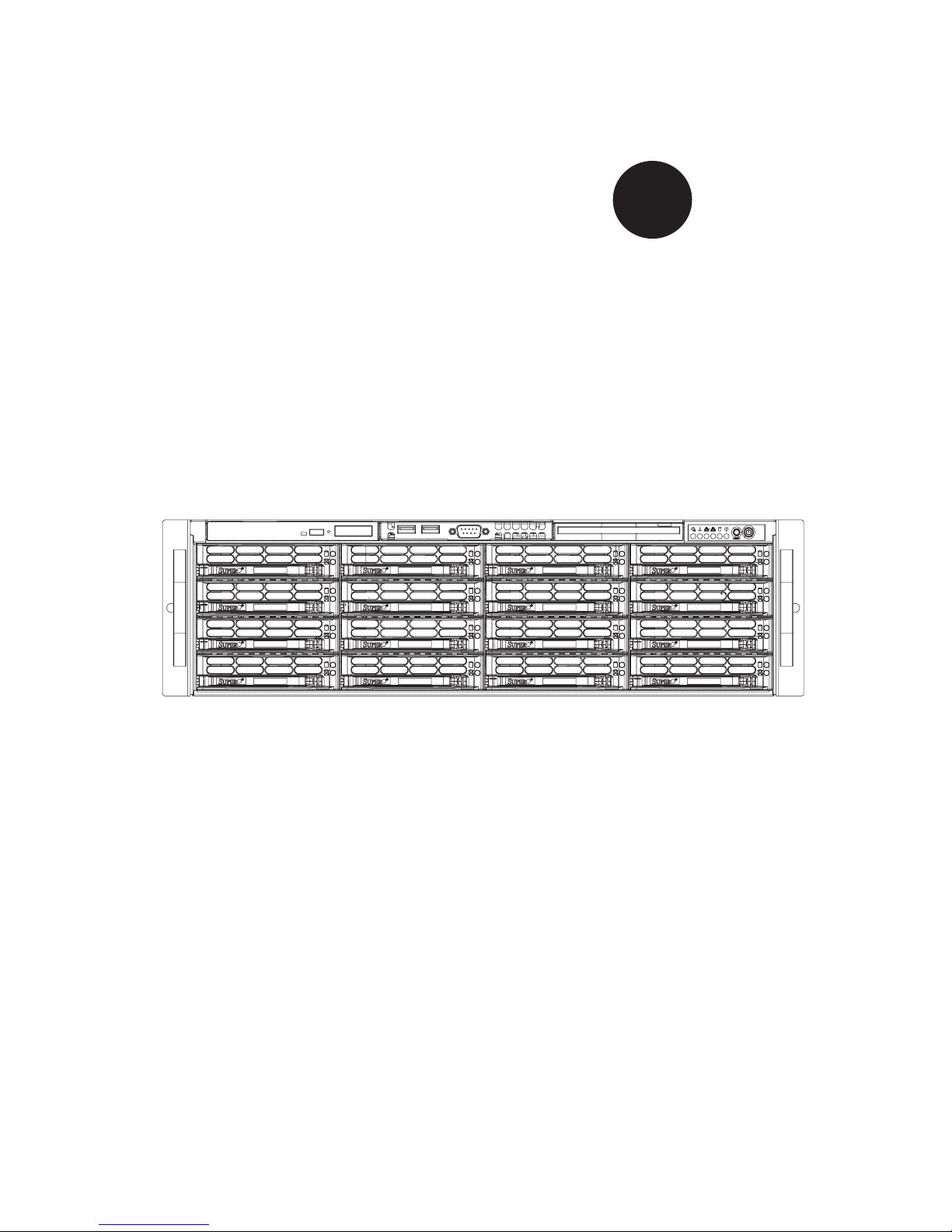
SUPERSERVER 6035B-8R+
®
USER’S MANUAL
1.0

The information in this User’s Manual has been carefully reviewed and is believed to be accurate.
The vendor assumes no responsibility for any inaccuracies that may be contained in this document,
makes no commitment to update or to keep current the information in this manual, or to notify any
person or organization of the updates. Please Note: For the most up-to-date version of this
manual, please see our web site at www.supermicro.com.
SUPERMICRO COMPUTER reserves the right to make changes to the product described in this
manual at any time and without notice. This product, including software, if any, and documentation may not, in whole or in part, be copied, photocopied, reproduced, translated or reduced to any
medium or machine without prior written consent.
IN NO EVENT WILL SUPERMICRO COMPUTER BE LIABLE FOR DIRECT, INDIRECT, SPECIAL,
INCIDENTAL, SPECULATIVE OR CONSEQUENTIAL DAMAGES ARISING FROM THE USE
OR INABILITY TO USE THIS PRODUCT OR DOCUMENTATION, EVEN IF ADVISED OF THE
POSSIBILITY OF SUCH DAMAGES. IN PARTICULAR, THE VENDOR SHALL NOT HAVE
LIABILITY FOR ANY HARDWARE, SOFTWARE, OR DATA STORED OR USED WITH THE
PRODUCT, INCLUDING THE COSTS OF REPAIRING, REPLACING, INTEGRATING, INSTALLING
OR RECOVERING SUCH HARDWARE, SOFTWARE, OR DATA.
Any disputes arising between manufacturer and customer shall be governed by the laws of Santa
Clara County in the State of California, USA. The State of California, County of Santa Clara shall
be the exclusive venue for the resolution of any such disputes. Supermicro's total liability for all
claims will not exceed the price paid for the hardware product.
Manual Revision 1.0
Release Date: October 26, 2006
Unless you request and receive written permission from SUPER MICRO COMPUTER, you may not
copy any part of this document.
Information in this document is subject to change without notice. Other products and companies
referred to herein are trademarks or registered trademarks of their respective companies or mark
holders.
Copyright © 2006 by SUPER MICRO COMPUTER INC.
All rights reserved.
Printed in the United States of America

Preface
About This Manual
This manual is written for professional system integrators and PC technicians. It
provides information for the installation and use of the SuperServer 6035B-8R+.
Installation and maintainance should be performed by experienced technicians
only.
The SuperServer 6035B-8R+ is a high-end server based on the SC836S2-R800 3U
rackmount chassis and the X7DB8+, a dual processor serverboard that supports
dual Intel
MHz and up to 64 GB of registered FBD ECC DDR2-667/533 SDRAM.
®
XeonTM LGA 771 processors at a Front Side (System) Bus speed of 1333
Preface
Manual Organization
Chapter 1: Introduction
The fi rst chapter provides a checklist of the main components included with the
server system and describes the main features of the X7DB8+ serverboard and the
SC836S2-R800 chassis, which comprise the SuperServer 6035B-8R+.
Chapter 2: Server Installation
This chapter describes the steps necessary to install the SuperServer 6035B-8R+
into a rack and check out the server confi guration prior to powering up the system.
If your server was ordered without processor and memory components, this chapter
will refer you to the appropriate sections of the manual for their installation.
Chapter 3: System Interface
Refer here for details on the system interface, which includes the functions and
information provided by the control panel on the chassis as well as other LEDs
located throughout the system.
iii

SUPERSERVER 6035B-8R+ User's Manual
Chapter 4: System Safety
You should thoroughly familiarize yourself with this chapter for a general overview
of safety precautions that should be followed when installing and servicing the
SuperServer 6035B-8R+.
Chapter 5: Advanced Serverboard Setup
Chapter 5 provides detailed information on the X7DB8+ serverboard, including the
locations and functions of connections, headers and jumpers. Refer to this chapter
when adding or removing processors or main memory and when reconfi guring the
serverboard.
Chapter 6: Advanced Chassis Setup
Refer to Chapter 6 for detailed information on the SC836S2-R800 server chassis.
You should follow the procedures given in this chapter when installing, removing or
reconfi guring SCSI or peripheral drives and when replacing system power supply
units and cooling fans.
Chapter 7: BIOS
The BIOS chapter includes an introduction to BIOS and provides detailed informa-
tion on running the CMOS Setup Utility.
Appendix A: BIOS POST Codes
Appendix B: BIOS POST Messages
Appendix C: System Specifi cations
iv

Notes
Preface
v
SUPERSERVER 6035B-8R+ User's Manual
Table of Contents
Preface
About This Manual ...................................................................................................... iii
Manual Organization ................................................................................................... iii
Chapter 1: Introduction
1-1 Overview ......................................................................................................... 1-1
1-2 Serverboard Features ..................................................................................... 1-2
1-3 Server Chassis Features ................................................................................ 1-4
1-4 Contacting Supermicro ................................................................................... 1-6
Chapter 2: Server Installation
2-1 Overview ......................................................................................................... 2-1
2-2 Unpacking the System ................................................................................... 2-1
2-3 Preparing for Setup ........................................................................................ 2-1
2-4 Installing the System into a Rack ................................................................... 2-4
2-5 Checking the Serverboard Setup ................................................................... 2-8
2-6 Checking the Drive Bay Setup ..................................................................... 2-10
Chapter 3: System Interface
3-1 Overview ......................................................................................................... 3-1
3-2 Control Panel Buttons .................................................................................... 3-1
Reset ........................................................................................................ 3-1
Power ....................................................................................................... 3-1
3-3 Control Panel LEDs ........................................................................................ 3-2
Power Fail ................................................................................................ 3-2
Overheat/Fan Fail .................................................................................... 3-2
NIC1 ......................................................................................................... 3-2
NIC2 ......................................................................................................... 3-2
HDD .......................................................................................................... 3-3
Power ....................................................................................................... 3-3
3-4 SCSI Drive Carrier LEDs ................................................................................ 3-3
Chapter 4: System Safety
4-1 Electrical Safety Precautions .......................................................................... 4-1
4-2 General Safety Precautions ........................................................................... 4-2
4-3 ESD Precautions ............................................................................................ 4-3
4-4 Operating Precautions .................................................................................... 4-4
vi

Table of Contents
Chapter 5: Advanced Serverboard Setup
5-1 Handling the Serverboard .............................................................................. 5-1
5-2 Processor and Heatsink Installation ............................................................... 5-2
5-3 Connecting Cables ......................................................................................... 5-5
Connecting Data Cables .......................................................................... 5-5
Connecting Power Cables ....................................................................... 5-5
Connecting the Control Panel .................................................................. 5-6
5-4 I/O Ports ......................................................................................................... 5-7
5-5 Installing Memory ........................................................................................... 5-7
5-6 Adding PCI Cards ........................................................................................... 5-9
5-7 Serverboard Details ...................................................................................... 5-10
X7DB8+ Layout ...................................................................................... 5-10
X7DB8+ Quick Reference ...................................................................... 5-11
5-8 Connector Defi nitions ................................................................................... 5-12
ATX Power Connector ........................................................................... 5-12
Secondary Power Connector ................................................................. 5-12
Processor Power Connector .................................................................. 5-12
NMI Button ............................................................................................. 5-12
Power LED ............................................................................................. 5-12
HDD LED ............................................................................................... 5-13
NIC1 LED ............................................................................................... 5-13
NIC2 LED ............................................................................................... 5-13
Overheat/Fan Fail LED .......................................................................... 5-13
Power Fail LED ...................................................................................... 5-13
Reset Button .......................................................................................... 5-14
Power Button .......................................................................................... 5-14
Universal Serial Bus Ports (USB0/1) ..................................................... 5-14
Chassis Intrusion .................................................................................... 5-14
Serial Ports ............................................................................................. 5-15
Power Fail Header ................................................................................. 5-15
Fan Headers .......................................................................................... 5-15
Universal Serial Bus Headers ................................................................ 5-16
Power LED/Speaker ............................................................................... 5-16
ATX PS/2 Keyboard and Mouse Ports .................................................. 5-16
Overheat LED ........................................................................................ 5-16
Wake-On-LAN ........................................................................................ 5-17
Wake-On-Ring ........................................................................................ 5-17
SMB ........................................................................................................ 5-17
SMBUS_PS ............................................................................................ 5-17
vii

SUPERSERVER 6035B-8R+ User's Manual
SGPIO .................................................................................................... 5-18
5-9 Jumper Settings ............................................................................................ 5-18
Explanation of Jumpers ......................................................................... 5-18
CMOS Clear ........................................................................................... 5-18
JLAN Enable/Disable ............................................................................. 5-19
Watch Dog Enable/Disable .................................................................... 5-19
3rd Power Supply Fail Detect Enable/Disable ....................................... 5-19
Alarm Reset ........................................................................................... 5-20
SCSI Controller Enable/Disable ............................................................. 5-20
SCSI Termination Enable/Disable .......................................................... 5-20
Compact Flash Master/Slave Select ...................................................... 5-21
SMBUS to PCI Enable/Disable .............................................................. 5-21
VGA Enable/Disable ............................................................................... 5-21
5-10 Onboard Indicators ....................................................................................... 5-22
JLAN1/JLAN2 LEDs ............................................................................... 5-22
SCSI Activity LED Indicators .................................................................. 5-22
Onboard Power LED .............................................................................. 5-22
5-11 Parallel Port, Floppy and Hard Drive Connections ...................................... 5-23
Parallel Port Connector .......................................................................... 5-23
Floppy Connector ................................................................................... 5-24
SATA Ports ............................................................................................. 5-24
IDE Connectors ...................................................................................... 5-25
Ultra320 SCSI Connectors ..................................................................... 5-26
5-12 Installing Software ........................................................................................ 5-27
Chapter 6: Advanced Chassis Setup
6-1 Static-Sensitive Devices ................................................................................. 6-1
6-2 Control Panel .................................................................................................. 6-2
6-3 System Fans ................................................................................................... 6-3
System Fan Failure .................................................................................. 6-3
Replacing System Fans ........................................................................... 6-3
6-4 Drive Bay Installation/Removal ...................................................................... 6-4
SCSI Drive Installation ............................................................................. 6-5
DVD-ROM and Floppy Drive Installation ................................................. 6-8
6-5 Power Supply ................................................................................................. 6-9
Power Supply Failure ............................................................................... 6-9
Removing/Replacing the Power Supply ................................................... 6-9
viii

Table of Contents
Chapter 7: BIOS
7-1 Introduction ..................................................................................................... 7-1
7-2 Running Setup ................................................................................................ 7-2
7-3 Main BIOS Setup ............................................................................................ 7-2
7-4 Advanced Setup ............................................................................................. 7-7
7-5 Security ......................................................................................................... 7-19
7-6 Boot .............................................................................................................. 7-20
7-7 Exit ................................................................................................................ 7-21
Appendices:
Appendix A: BIOS POST Messages ........................................................................ A-1
Appendix B: BIOS POST Codes .............................................................................. B-1
Appendix C: System Specifi cations ........................................................................ C-1
ix

S
UPERSERVER 6035B-8R+ User's Manual
Notes
x

Chapter 1: Introduction
Chapter 1
Introduction
1-1 Overview
The SuperServer 6035B-8R+ is a high-end server that is comprised of two main
subsystems: the SC836S2-R800 3U server chassis and the X7DB8+ dual Intel Xeon
processor serverboard. Please refer to our web site for information on operating
systems that have been certifi ed for use with the SuperServer 6035B-8R+ (www.
supermicro.com).
In addition to the serverboard and chassis, various hardware components have
been included with the SuperServer 6035B-8R+, as listed below:
Three (3) 8-cm hot-swap chassis fans (FAN-0070L)
One (1) air shroud (MCP-310-00004-00)
Two (2) CPU passive heatsinks (SNK-P0018)
One (1) DVD-ROM drive (DVM-PNSC-824)
One (1) ATA66 cable for DVD drive (CBL-0139L)
One (1) fl oppy cable (CBL-0078)
One (1) rail set (MCP-290-00001-00)
SCSI Accessories
One (1) dual-channel SCSI backplane (BPN-SCA-836S2)
One (1) Ultra320 SCSI ribbon cable (CBL-0043L)
One (1) Ultra320 SCSI round cable (CBL-0063L)
Sixteen (16) hot-swap SCSI drive carriers [MCP-220-00001-01(03)]
Note: The 6035B-8R+ is available in silver and black; for the server, a "V" (6035B-
8R+V) indicates silver and a "B" (6035B-8R+B) indicates black. A "03" following a
part number indicates silver and "01" indicates black.
1-1

S
UPERSERVER 6035B-8R+ User's Manual
1-2 Serverboard Features
At the heart of the SuperServer 6035B-8R+ lies the X7DB8+, a dual processor
serverboard based on the Intel 5000P chipset and designed to provide maximum
performance. Below are the main features of the X7DB8+. (See Figure 1-1 for a
block diagram of the 5000P chipset).
Processors
The X7DB8+ supports single or dual LGA 771 type Intel Xeon processors at a FSB
speed of 1333 MHz. Please refer to the serverboard description pages on our web
site for a complete listing of supported processors (www.supermicro.com).
Memory
The X7DB8+ has sixteen 240-pin DIMM slots that can support up to 64 GB of FBD
(Fully Buffered DIMM) ECC DDR2-667/533 SDRAM. The memory operates in a
4-way interleaved confi gurations and requires requires modules of the same size
and speed to be installed four at a time. See Chapter 5 Section 5 for details.
Onboard SCSI
An onboard Adaptec AIC-7902 dual-channel SCSI controller in integrated into the
X7DB8+, which supports eight 80-pin SCA Ultra320 SCSI hard drives. The SCSI
drives are connected to an SCA backplane that provides power, bus termination
and confi guration settings. The SCSI drives are hot-swappable units.
Note: The operating system you use must have RAID support to enable the hot-
swap capability and RAID function of the SCSI drives.
Serial ATA
A SATA controller is integrated into the South Bridge of the 5000P chipset to
provide a six-port Serial ATA subsystem, which is RAID 0, 1, 10 and 5 supported.
The Serial ATA drives are hot-swappable units.
Note: The operating system you use must have RAID support to enable the hot-
swap capability and RAID function of the Serial ATA drives.
1-2

Chapter 1: Introduction
PCI Expansion Slots
The X7DB8+ has six PCI expansion slots, which includes two PCI-Express x8
slots, one PCI-Express x4 slot, two 64-bit 133 MHz PCI-X slots and one 64-bit 100
MHz PCI-X slot. (On the X7DB8+, one 100 MHz PCI slot supports Zero Channel
RAID.)
Onboard Controllers/Ports
One fl oppy drive controller and two onboard ATA/100 controllers are provided to
support up to four IDE hard drives or ATAPI devices. The color-coded I/O ports
include one COM port (an additional COM header is located on the serverboard), a
VGA (monitor) port, a parallel port, two USB 2.0 ports, PS/2 mouse and keyboard
ports and two gigabit Ethernet ports.
ATI Graphics Controller
The X7DB8+ features an integrated ATI video controller based on the ES1000
graphics chip. The ES1000 was designed specifi cally for servers, featuring low
power consumption, high reliability and superior longevity.
Other Features
Other onboard features that promote system health include onboard voltage moni-
tors, a chassis intrusion header, auto-switching voltage regulators, chassis and CPU
overheat sensors, virus protection and BIOS rescue.
1-3

S
UPERSERVER 6035B-8R+ User's Manual
1-3 Server Chassis Features
The following is a general outline of the main features of the SC836S2-R800 server
chassis.
System Power
The SC836S2-R800 features a redundant (two separate power modules) 800W
high-effi ciency power supply with I
to replace a failed power supply without shutting down the system.
SCSI Subsystem
The SC836S2-R800 chassis was designed to support sixteen dual-channel SCSI
hard drives, which are hot-swappable units.
Note: The operating system you use must have RAID support to enable the hot-
swap capability of the SCSI drives.
2
C. This power redundancy feature allows you
Front Control Panel
The control panel on the SuperServer 6035B-8R+ provides you with system monitor-
ing and control. LEDs indicate system power, HDD activity, network activity, system
overheat and power supply failure. A main power button and a system reset button
are also included. In addition, two USB ports and a COM port have been incorpo-
rated into the front of the chassis for convenient access.
I/O Backplane
The SC836S2-R800 is an ATX form factor chassis designed to be used in a 3U
rackmount confi guration. The I/O backplane provides seven PCI expansion slots,
one COM port, a parallel port, a VGA port, two USB 2.0 ports, PS/2 mouse and
keyboard ports and two gigabit Ethernet ports.
Cooling System
The SC836S2-R800 chassis includes three 8-cm hot-plug system cooling fans
located in the middle section of the chassis. An air shroud channels the airfl ow
from the system fans to effi ciently cool the processors and memory. Two additional
8-cm fans are located at the back of the chassis to expel hot air from the system.
Each power supply modules also include a cooling fan.
1-4
Chapter 1: Introduction
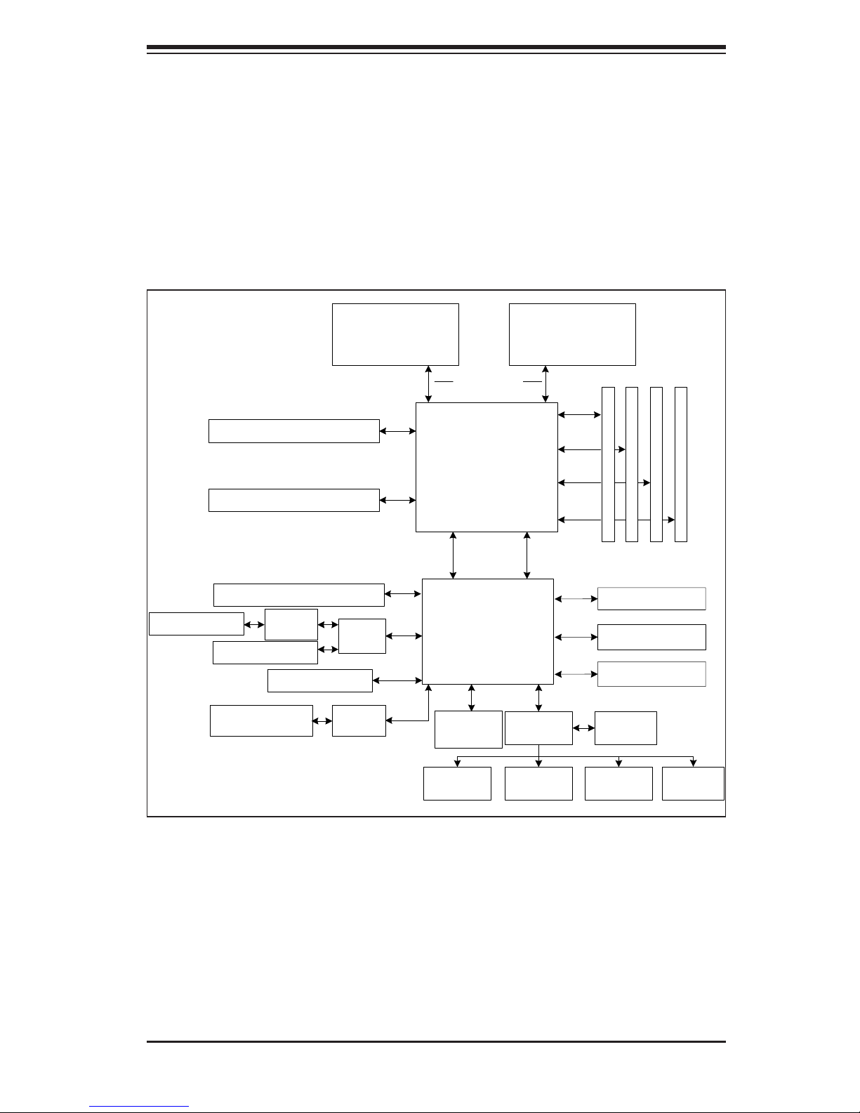
Figure 1-1. Intel 5000P/ESB2 Chipset:
System Block Diagram
Note: This is a general block diagram. Please see Chapter 5 for details.
Slot 6: PCI-Exp x8/SEPC
Slot 2: PCI-X
LAN Ports (2)
Slot 5: PCI-Express x8
Slot 4: PCI-Express x8
AIC
7902
PXH
Slot 1: PCI-X
Slot 3: PCI-X
82563
CPU1
PCI-Exp
x8
PCI-Exp
x8
PCI-Exp
x4
PCI-Exp
x8
PCI-X 133
Kumeran
1067/1333 MT/s
5000P
MCH
PCI -E x 8
ESB2
PCI 32
ATI
ES1000
CPU2
FBD CH0
FBD CH1
FBD CH2
FBD CH3
PCI -E x 4
3.0 Gb/s
ATA 100
USB 2.0
LPC
FBD DI MM Bank1
DDR2
SATA Ports (6)
IDE Ports (2)
USB Ports (5)
S I/O BIOS
FBD DI MM Bank2
FBD DI MM Bank3
FBD DI MM Bank4
Kybd/
Mouse
1-5
Floppy
COM
Ports (2)
Parallel
Port

S
UPERSERVER 6035B-8R+ User's Manual
1-4 Contacting Supermicro
Headquarters
Address: SuperMicro Computer, Inc.
980 Rock Ave.
San Jose, CA 95131 U.S.A.
Tel: +1 (408) 503-8000
Fax: +1 (408) 503-8008
Email: marketing@supermicro.com (General Information)
support@supermicro.com (Technical Support)
Web Site: www.supermicro.com
Europe
Address: SuperMicro Computer B.V.
Het Sterrenbeeld 28, 5215 ML
's-Hertogenbosch, The Netherlands
Tel: +31 (0) 73-6400390
Fax: +31 (0) 73-6416525
Email: sales@supermicro.nl (General Information)
support@supermicro.nl (Technical Support)
rma@supermicro.nl (Customer Support)
Asia-Pacifi c
Address: SuperMicro, Taiwan
4F, No. 232-1, Liancheng Rd.
Chung-Ho 235, Taipei, Taiwan, R.O.C.
Tel: +886-(2) 8226-3990
Fax: +886-(2) 8226-3991
Web Site: www.supermicro.com.tw
Technical Support:
Email: support@supermicro.com.tw
Tel: 886-2-8228-1366, ext.132 or 139
1-6

Chapter 2: Server Installation
Chapter 2
Server Installation
2-1 Overview
This chapter provides a quick setup checklist to get your SuperServer 6035B-8R+
up and running. Following these steps in the order given should enable you to have
the system operational within a minimum amount of time. This quick setup assumes
that your system has come to you with the processors and memory preinstalled. If
your system is not already fully integrated with a serverboard, processors, system
memory etc., please turn to the chapter or section noted in each step for details on
installing specifi c components.
2-2 Unpacking the System
You should inspect the box the SuperServer 6035B-8R+ was shipped in and note
if it was damaged in any way. If the server itself shows damage you should fi le a
damage claim with the carrier who delivered it.
Decide on a suitable location for the rack unit that will hold the SuperServer 6035B-
8R+. It should be situated in a clean, dust-free area that is well ventilated. Avoid
areas where heat, electrical noise and electromagnetic fi elds are generated. You
will also need it placed near a grounded power outlet. Read the Rack and Server
Precautions in the next section.
2-3 Preparing for Setup
The box the SuperServer 6035B-8R+ was shipped in should include two sets of
rail assemblies, two rail mounting brackets and the mounting screws you will need
to install the system into the rack. Follow the steps in the order given to complete
the installation process in a minimum amount of time. Please read this section
in its entirety before you begin the installation procedure outlined in the sections
that follow.
2-1
S
UPERSERVER 6035B-8R+ User's Manual
Choosing a Setup Location
- Leave enough clearance in front of the rack to enable you to open the front
door completely (~25 inches).
- Leave approximately 30 inches of clearance in the back of the rack to allow
for suffi cient airfl ow and ease in servicing.
- This product is for installation only in a Restricted Access Location (dedicated
equipment rooms, service closets, etc.).
!
Warnings and Precautions!
!
Rack Precautions
- Ensure that the leveling jacks on the bottom of the rack are fully extended to
the fl oor with the full weight of the rack resting on them.
- In single rack installation, stabilizers should be attached to the rack.
- In multiple rack installations, the racks should be coupled together.
- Always make sure the rack is stable before extending a component from the
rack.
- You should extend only one component at a time - extending two or more
simultaneously may cause the rack to become unstable.
Server Precautions
- Review the electrical and general safety precautions in Chapter 4.
- Determine the placement of each component in the rack before you install the
rails.
- Install the heaviest server components on the bottom of the rack fi rst, and then
work up.
- Use a regulating uninterruptible power supply (UPS) to protect the server from
power surges, voltage spikes and to keep your system operating in case of a power
failure.
- Allow the hot plug SCSI drives and power supply units to cool before touching
them.
-
Always keep the rack's front door and all panels and components on the servers
closed when not servicing to maintain proper cooling.
2-2

Chapter 2: Server Installation
Rack Mounting Considerations
Ambient Operating Temperature
If installed in a closed or multi-unit rack assembly, the ambient operating tempera-
ture of the rack environment may be greater than the ambient temperature of the
room. Therefore, consideration should be given to installing the equipment in an
environment compatible with the manufacturer’s maximum rated ambient tempera-
ture (Tmra).
Reduced Airfl ow
Equipment should be mounted into a rack so that the amount of airfl ow required
for safe operation is not compromised.
Mechanical Loading
Equipment should be mounted into a rack so that a hazardous condition does not
arise due to uneven mechanical loading.
Circuit Overloading
Consideration should be given to the connection of the equipment to the power
supply circuitry and the effect that any possible overloading of circuits might have
on overcurrent protection and power supply wiring. Appropriate consideration of
equipment nameplate ratings should be used when addressing this concern.
Reliable Ground
A reliable ground must be maintained at all times. To ensure this, the rack itself
should be grounded. Particular attention should be given to power supply connec-
tions other than the direct connections to the branch circuit (i.e. the use of power
strips, etc.).
2-3
S
UPERSERVER 6035B-8R+ User's Manual
2-4 Installing the System into a Rack
This section provides information on installing the SuperServer 6035B-8R+ into a
rack unit. If the 6035B-8R+ has already been mounted into a rack, you can skip
ahead to Sections 2-5 and 2-6. There are a variety of rack units on the market, which
may mean the assembly procedure will differ slightly. The following is a guideline for
installing the 6035B-8R+ into a rack with the rack rails provided. You should also
refer to the installation instructions that came with the rack unit you are using.
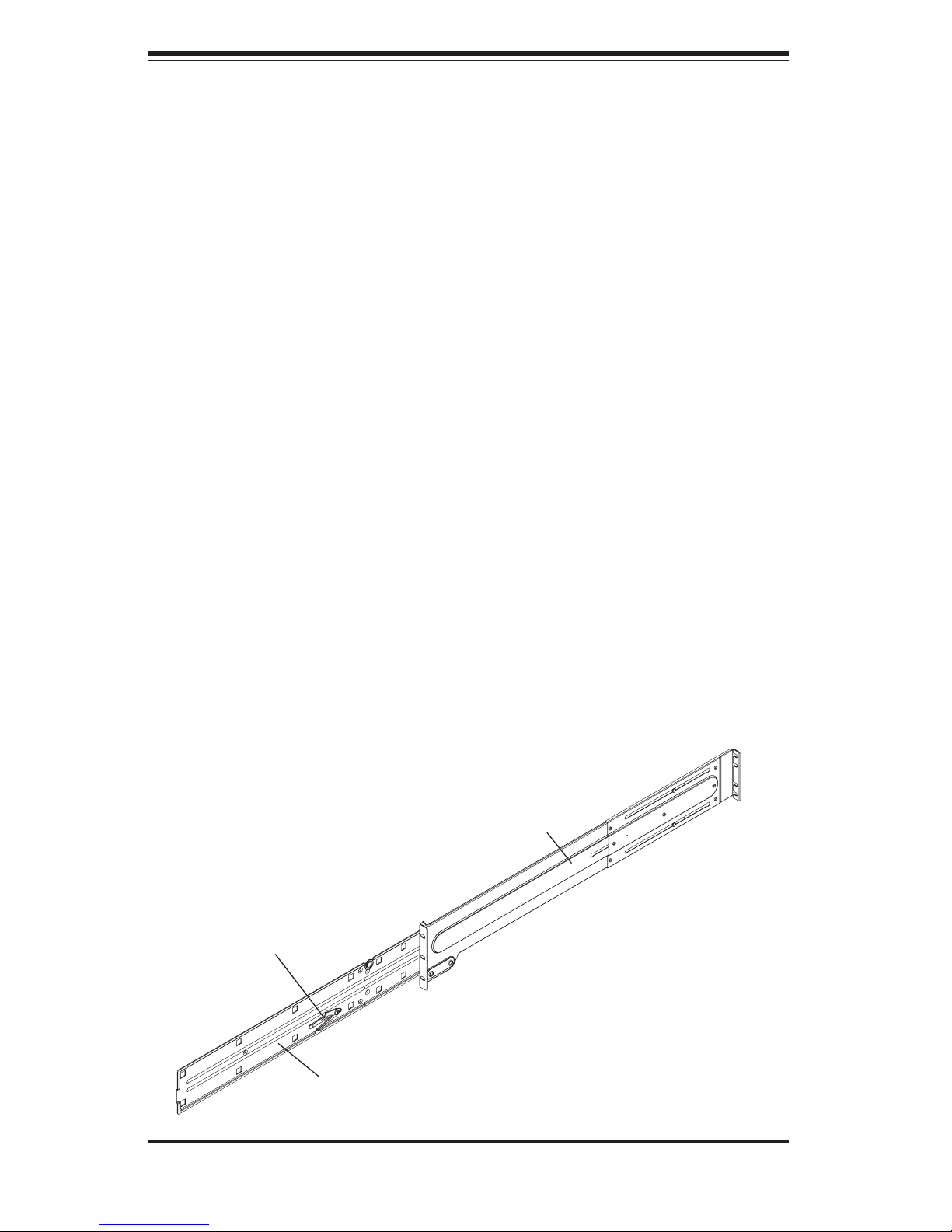
Identifying the Sections of the Rack Rails
You should have received two rack rail assemblies with the SuperServer 6035B-
8R+. Each of these assemblies consist of two sections: an inner chassis rail that
secures to the chassis (A) and an outer rack rail that secures directly to the rack
itself (B). All screws and hardware mentioned in the installation steps should be
included in the hardware kit.
To remove the chassis rail (A), pull it out as far as possible - you should hear a
"click" sound as a locking tab emerges from inside the rail assembly and locks the
inner rail. Then depress the locking tab to pull the inner rail completely out. Do
this for both the left and right side rack rail assemblies.
Figure 2-1. Identifying the Sections of the Rack Rails
B
Locking Tab
A
2-4
Chapter 2: Server Installation
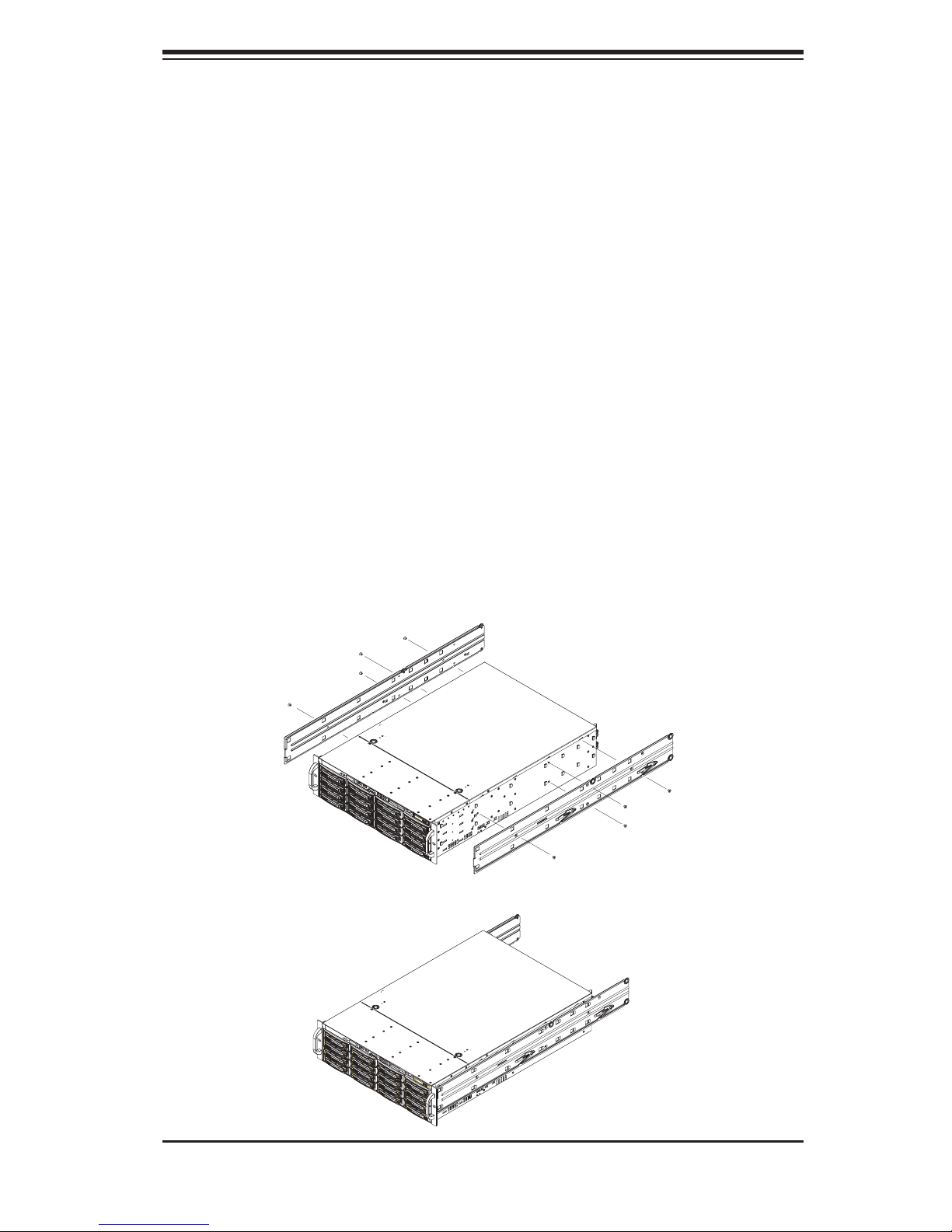
Installing the Chassis Rails
Position one of the chassis rail sections you just removed along the side of the
6035B-8R+. Note that the two chassis rails are left/right specifi c. Locate the numer-
ous rail tabs on each side of the chassis and the corresponding holes on each of
the chassis rails. Note that the holes are elongated with one end of the hole larger
than the other. Align the larger end of each hole with its corresponding tab. With
all holes and tabs aligned, position the rail onto the side of the chassis (see Figure
2-2). Once a rail is positioned on the chassis, pull it forward until the rail tabs lock
in the small ends of the corresponding holes. Then secure the rail to the chassis
with the screws included in the harware kit. Repeat the above steps to install the
other rail on the chassis.
Locking Tabs: As mentioned, both chassis rails have locking tabs, which serve to
lock the server into place when installed and pushed fully into the rack (its normal
position).
Figure 2-2. Installing Chassis Rails
2-5
S
UPERSERVER 6035B-8R+ User's Manual
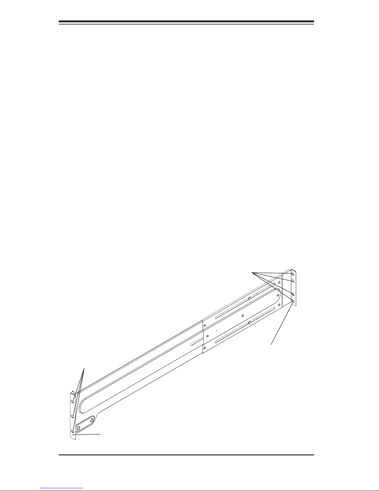
Installing the Server into the Rack
Locate the front and rear brackets that on both ends of the outer chassis rail. These
brackets sit perpendicular to the rail and are used to attached the rail to the rack.
Secure the front bracket to the rack with two screws and the rear bracket to the
rack with four screws using the appropriate screws and washers included in the
hardware kit (see Figure 2-3). You may need to adjust the rail to match the depth
of the rack. Repeat the same steps to install the other outer rail to the rack.
You are now ready to install the server into the rack. Slide the chassis into the
rack as shown in Figure 2-4. The chassis may not slide into the rack smoothly or
easily when installed the fi rst time. Some adjustment to the slide assemblies might
be needed for easier installation.
When the server has been pushed completely into the rack, you should hear the
locking tabs "click". You'll need to release the safety taps on both sides of the
chassis in order to completely remove the chassis out of the rack.
Screws
Figure 2-3. Assembling the Rack Rails
Screws
Rear Bracket
Front Bracket
2-6
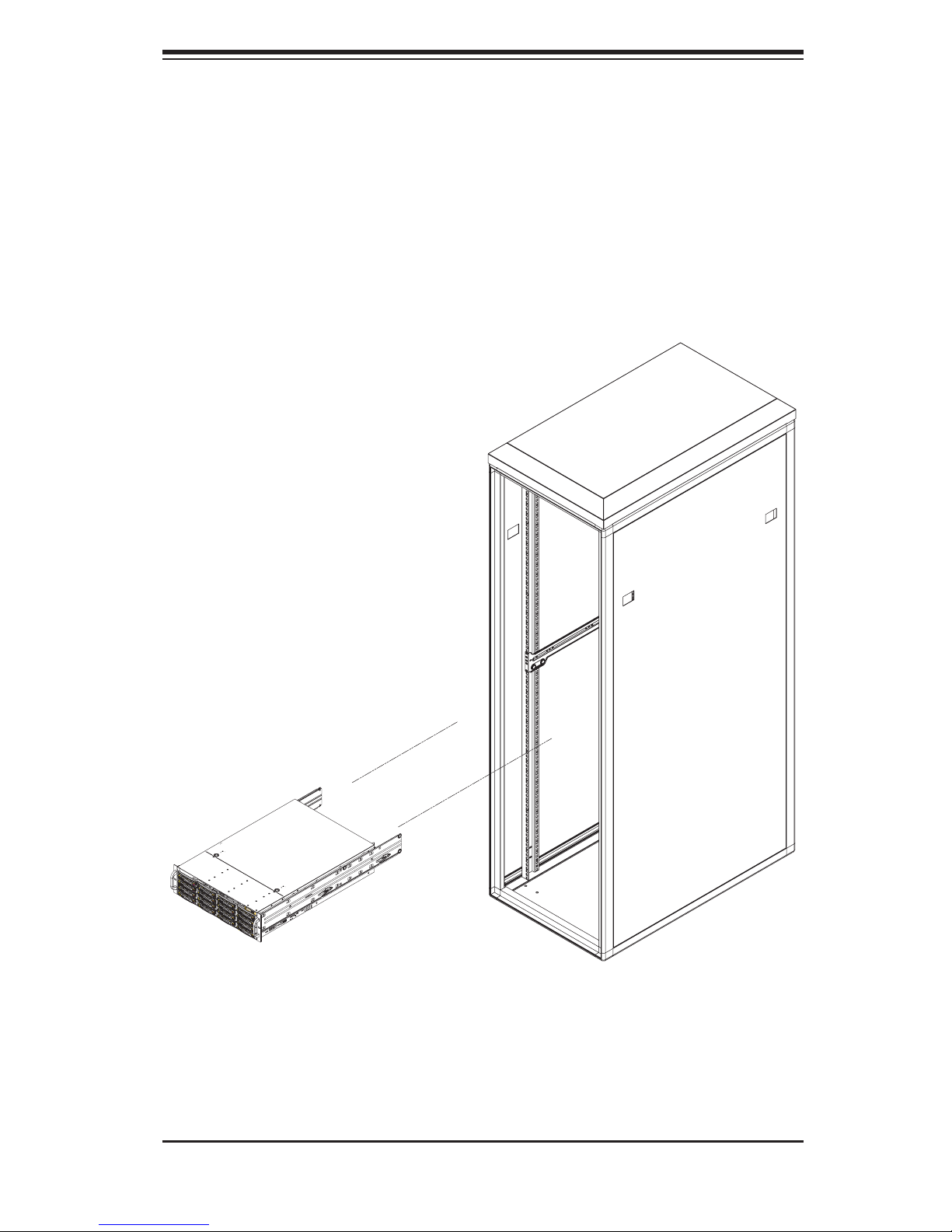
Chapter 2: Server Installation
Figure 2-4. Installing the Server into a Rack
2-7

S
UPERSERVER 6035B-8R+ User's Manual
2-5 Checking the Serverboard Setup
After you install the 6035B-8R+ in the rack, you will need to open the unit to
make sure the serverboard is properly installed and all the connections have been
made.
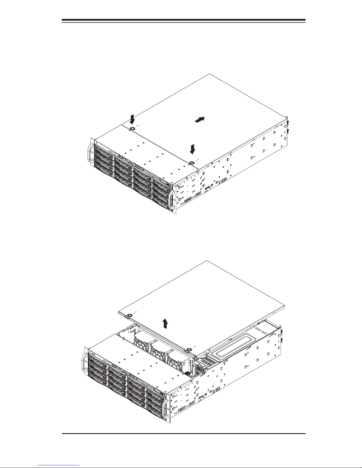
1. Accessing the inside of the System (see Figure 2-5)
First, release the retention screws that secure the unit to the rack. Grasp the two
handles on either side and pull the unit straight out until it locks (you will hear a
"click"). Next, depress the two buttons on the top of the chassis and push the cover
toward the rear of the chassis to release it. You can then lift the cover from the
chassis to gain full access to the inside of the server.
2. Check the CPUs (processors)
You may have one or two processors already installed into the serverboard. Each
processor needs its own heatsink. See Chapter 5 for instructions on processor and
heatsink installation.
3. Check the system memory
Your server system may have come with system memory already installed. Make
sure all DIMMs are fully seated in their slots. For details on adding system memory,
refer to Chapter 5.
4. Installing add-on cards
If desired, you can install add-on cards to the system. See Chapter 5 for details
on installing PCI add-on cards.
5. Check all cable connections and airfl ow
Make sure all power and data cables are properly connected and not blocking the
chassis airfl ow. Also make sure that no cables are positioned in front of the fans.
See Chapter 5 for details on cable connections.
2-8
Chapter 2: Server Installation
Figure 2-5. Accessing the Inside of the System
2-9

S
UPERSERVER 6035B-8R+ User's Manual
2-6 Checking the Drive Bay Setup
Next, you should check to make sure the peripheral drives and the SCSI drives
and SCSI backplane have been properly installed and all connections have been
made.
1. Accessing the drive bays
All drives are accessable from the front of the server. For servicing the DVD-ROM
and fl oppy drives, you will need to remove the top chassis cover. The SCSI disk
drives can be installed and removed from the front of the chassis without removing
the top chassis cover.
2. DVD-ROM and fl oppy disk drives
A slim DVD-ROM and a fl oppy drive should be preinstalled in your server. Refer
to Chapter 6 if you need to reinstall a DVD-ROM and/or fl oppy disk drive to the
system.
3. Check the SCSI disk drives
Depending upon your system's confi guration, your system may have one or more
drives already installed. If you need to install SCSI drives, please refer to Chapter
6.
4. Check the airfl ow
Airfl ow is provided by three 8-cm chassis cooling fans and two 8-cm rear chassis
exhaust fans. An air shroud is also included in the system to maximize airfl ow. The
system component layout was carefully designed to direct suffi cient cooling airfl ow
to the components that generate the most heat. Note that all power and data cables
have been routed in such a way that they do not block the airfl ow generated by the
fans.
5. Supplying power to the system
The last thing you must do is to provide input power to the system. Plug the power
cord(s) from the power supply unit(s) into a high-quality power strip that offers pro-
tection from electrical noise and power surges. It is recommended that you use an
uninterruptible power supply (UPS).
2-10
Chapter 3: System Interface
Chapter 3
System Interface
3-1 Overview
There are several LEDs on the control panel as well as others on the SCSI drive
carriers to keep you constantly informed of the overall status of the system as well
as the activity and health of specifi c components. There are also two buttons on
the chassis control panel.
3-2 Control Panel Buttons
The two push-buttons located on the front of the chassis are (in order from left to
right) a reset button and a power on/off button.
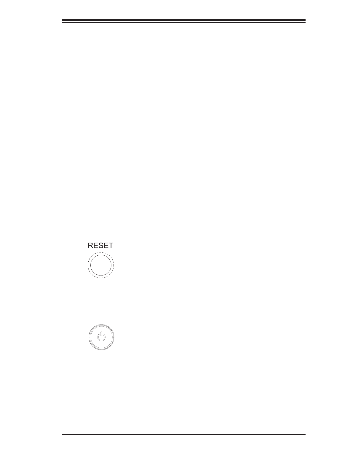
RESET:
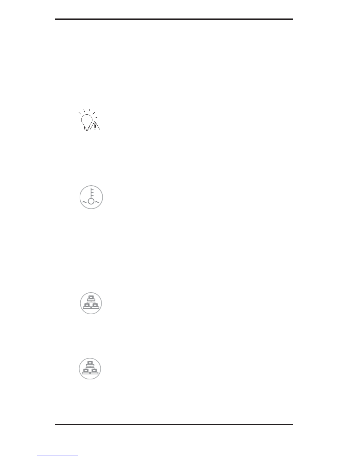
POWER: This is the main power button, which is used to apply or turn off
the main system power. Turning off system power with this button removes the
main power but keeps standby power supplied to the system.
Use the reset button to reboot the system.
3-1
SUPERSERVER 6035B-8R+ User's Manual
3-3 Control Panel LEDs
The control panel located on the front of the chassis has several LEDs. These
LEDs provide you with critical information related to different parts of the system.
This section explains what each LED indicates when illuminated and any corrective
action you may need to take.
Power Fail: Indicates a power supply module has failed. The second power
supply module will take the load and keep the system running but the failed module
will need to be replaced. Refer to Chapter 6 for details on replacing the power
supply. This LED should be off when the system is operating normally.
Overheat/Fan Fail: When this LED fl ashes, it indicates a fan failure. When
on continuously it indicates an overheat condition, which may be caused by cables
obstructing the airfl ow in the system or the ambient room temperature being too
warm. Check the routing of the cables and make sure all fans are present and
operating normally. You should also check to make sure that the chassis covers
are installed. Finally, verify that the heatsinks are installed properly (see Chapter
5). This LED will remain fl ashing or on as long as the indicated condition exists.
1
NIC1: Indicates network activity on the JLAN1 port when fl ashing.
2
NIC2: Indicates network activity on the JLAN2 port when fl ashing.
3-2
Chapter 3: System Interface
HDD: Indicates IDE channel activity. On the SuperServer 6035B-8R+, this
LED indicates SCSI and/or DVD-ROM drive activity when fl ashing.
Power:
This LED should normally be illuminated when the system is operating.
Indicates power is being supplied to the system's power supply units.
3-4 SCSI Drive Carrier LEDs
Each SCSI drive carrier has two LEDs.
Green: When illuminated, the green LED on the front of the SCSI drive car-
rier indicates drive activity. A connection to the SCSI SCA backplane enables this
LED to blink on and off when that particular drive is being accessed.
Red: The SAF-TE compliant backplane activates the red LED to indicate a
drive failure. If one of the SCSI drives fail, you should be notifi ed by your system
management software. Please refer to Chapter 6 for instructions on replacing failed
SCSI drives.
3-3

SUPERSERVER 6035B-8R+ User's Manual
Notes
3-4
 Loading...