

Supero SUPERSERVER 6027R-TRF User Manual
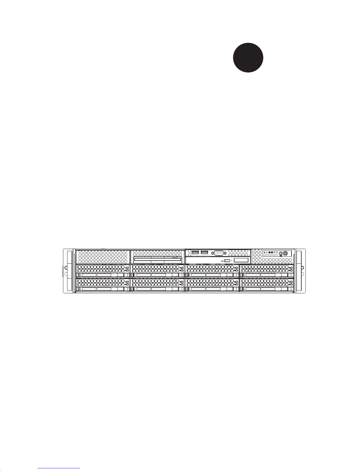
SUPERSERVER
6027R-TRF
®
SUPER
USER'S MANUAL
Revision 1.0a

The information in this User’s Manual has been carefully reviewed and is believed to be accurate.
The vendor assumes no responsibility for any inaccuracies that may be contained in this document,
makes no commitment to update or to keep current the information in this manual, or to notify any
person or organization of the updates. Please Note: For the most up-to-date version of this
manual, please see our web site at www.supermicro.com.
Super Micro Computer, Inc. ("Supermicro") reserves the right to make changes to the product
described in this manual at any time and without notice. This product, including software and
documentation, is the property of Supermicro and/or its licensors, and is supplied only under a
license. Any use or reproduction of this product is not allowed, except as expressly permitted by
the terms of said license.
IN NO EVENT WILL SUPERMICRO BE LIABLE FOR DIRECT, INDIRECT, SPECIAL, INCIDENTAL,
SPECULATIVE OR CONSEQUENTIAL DAMAGES ARISING FROM THE USE OR INABILITY TO
USE THIS PRODUCT OR DOCUMENTATION, EVEN IF ADVISED OF THE POSSIBILITY OF
SUCH DAMAGES. IN PARTICULAR, SUPERMICRO SHALL NOT HAVE LIABILITY FOR ANY
HARDWARE, SOFTW ARE, OR DA TA STORED OR USED WITH THE PRODUCT, INCLUDING THE
COSTS OF REPAIRING, REPLACING, INTEGRATING, INSTALLING OR RECOVERING SUCH
HARDWARE, SOFTWARE, OR DATA.
Any disputes arising between manufacturer and customer shall be governed by the laws of Santa
Clara County in the State of California, USA. The State of California, County of Santa Clara shall
be the exclusive venue for the resolution of any such disputes. Super Micro's total liability for all
claims will not exceed the price paid for the hardware product.
FCC Statement: This equipment has been tested and found to comply with the limits for a Class
A digital device pursuant to Part 15 of the FCC Rules. These limits are designed to provide
reasonable protection against harmful interference when the equipment is operated in a commercial
environment. This equipment generates, uses, and can radiate radio frequency energy and, if not
installed and used in accordance with the manufacturer’s instruction manual, may cause harmful
interference with radio communications. Operation of this equipment in a residential area is likely
to cause harmful interference, in which case you will be required to correct the interference at your
own expense.
California Best Management Practices Regulations for Perchlorate Materials: This Perchlorate
warning applies only to products containing CR (Manganese Dioxide) Lithium coin cells. “Perchlorate
Material-special handling may apply. See www.dtsc.ca.gov/hazardouswaste/perchlorate”
WARNING: Handling of lead solder materials used in this
product may expose you to lead, a chemical known to
the State of California to cause birth defects and other
reproductive harm.
Manual Revision 1.0a
Release Date: February 21, 2012
Unless you request and receive written permission from Super Micro Computer, Inc., you may not
copy any part of this document.
Information in this document is subject to change without notice. Other products and companies
referred to herein are trademarks or registered trademarks of their respective companies or mark
holders.
Copyright © 2012 by Super Micro Computer, Inc.
All rights reserved.
Printed in the United States of America
iii
Preface
Preface
About This Manual
This manual is written for professional system integrators and PC technicians. It
provides information for the installation and use of the SUPERSERVER 6027R-TRF
Installation and maintainance should be performed by experienced technicians only .
The SUPERSERVER 6027R-TRF is a high-end server based on the
SC825TS-R740LPBP 2U rackmount chassis and the X9DRi-F dual processor
serverboard.
Manual Organization
Chapter 1: Introduction
The fi rst chapter provides a checklist of the main components included with the
server system and describes the main features of the X9DRi-F serverboard and
the SC825TS-R740LPBP chassis.
Chapter 2: Server Installation
This chapter describes the steps necessary to install the SuperServer 6027R-TRF
into a rack and check out the server confi guration prior to powering up the system.
If your server was ordered without processor and memory components, this chapter
will refer you to the appropriate sections of the manual for their installation.
Chapter 3: System Interface
Refer here for details on the system interface, which includes the functions and
information provided by the control panel on the chassis as well as other LEDs
located throughout the system.
Chapter 4: System Safety
You should thoroughly familiarize yourself with this chapter for a general overview
of safety precautions that should be followed when installing and servicing the
SuperServer 6027R-TRF.
Chapter 5: Advanced Serverboard Setup
Chapter 5 provides detailed information on the X9DRi-F serverboard, including the
locations and functions of connections, headers and jumpers. Refer to this chapter
when adding or removing processors or main memory and when reconfi guring the
serverboard.
SUPERSERVER 6027R-TRF USER'S MANUAL
iv
Chapter 6: Advanced Chassis Setup
Refer to Chapter 6 for detailed information on the SC825TS-R740LPBP server
chassis. You should follow the procedures given in this chapter when installing,
removing or reconfi guring SAS/SATA or peripheral drives and when replacing
system power supply units and cooling fans.
Chapter 7: BIOS
The BIOS chapter includes an introduction to BIOS and provides detailed information
on running the CMOS Setup Utility for the X9DRi-F serverboard.
Appendix A: BIOS Error Beep Codes
Appendix B: Installing Windows
Appendix C: System Specifi cations

Notes
Preface
v
vi
Table of Contents
Chapter 1 Introduction
1-1 Overview .........................................................................................................1-1
1-2 Serverboard Features .....................................................................................1-2
Processors ......................................................................................................1-2
Memory ...........................................................................................................1-2
Serial ATA ....................................................................................................... 1-2
Onboard Controllers/Ports ..............................................................................1-2
Graphics Controller .........................................................................................1-2
Other Features ................................................................................................ 1-3
1-3 Server Chassis Features ................................................................................1-3
System Power ................................................................................................. 1-3
Hard Drive Subsystem .................................................................................... 1-3
PCI Expansion Slots ....................................................................................... 1-3
Front Control Panel ......................................................................................... 1-3
I/O Backplane ..................................................................................................1-4
Cooling System ............................................................................................... 1-4
1-4 Advanced Power Management (for -F Models Only) ..................................... 1-4
Intel® Intelligent Power Node Manager (NM) .................................................1-4
Manageability Engine (ME) ............................................................................. 1-4
1-5 Contacting Supermicro ....................................................................................1-6
Chapter 2 Server Installation
2-1 Overview .........................................................................................................2-1
2-2 Unpacking the System .................................................................................... 2-1
2-3 Preparing for Setup ......................................................................................... 2-1
Choosing a Setup Location .............................................................................2-1
Warnings and Precautions! ........................................................................................ 2-2
Rack Precautions ............................................................................................ 2-2
Server Precautions ..........................................................................................2-2
Rack Mounting Considerations ....................................................................... 2-3
Ambient Operating Temperature ................................................................ 2-3
Reduced Airfl ow ......................................................................................... 2-3
Mechanical Loading ................................................................................... 2-3
Circuit Overloading ..................................................................................... 2-3
Reliable Ground ......................................................................................... 2-3
2-4 Installing the System into a Rack ................................................................... 2-4
Separating the Sections of the Rack Rails ..................................................... 2-4
SUPERSERVER 6027R-TRF USER'S MANUAL

vii
Installing the Inner Rail Extension .................................................................. 2-4
Outer Rack Rails ............................................................................................. 2-6
2-5 Checking the Serverboard Setup ....................................................................2-8
2-6 Checking the Drive Bay Setup ......................................................................2-10
Chapter 3 System Interface
3-1 Overview .........................................................................................................3-1
3-2 Control Panel Buttons ..................................................................................... 3-1
Reset ...............................................................................................................3-1
Power ..............................................................................................................3-1
3-3 Control Panel LEDs ........................................................................................3-2
Power Fail ....................................................................................................... 3-2
Overheat/Fan Fail: .......................................................................................... 3-2
NIC1 ................................................................................................................3-2
NIC2 ................................................................................................................3-2
HDD ................................................................................................................. 3-3
Power ..............................................................................................................3-3
3-4 Drive Carrier LEDs .......................................................................................... 3-3
Chapter 4 System Safety
4-1 Electrical Safety Precautions .......................................................................... 4-1
4-2 General Safety Precautions ............................................................................ 4-2
4-3 ESD Precautions ............................................................................................. 4-3
4-4 Operating Precautions .................................................................................... 4-4
Chapter 5 Advanced Serverboard Setup
5-1 Handling the Serverboard ............................................................................... 5-1
Precautions .....................................................................................................5-1
Unpacking .......................................................................................................5-1
5-2 Processor and Heatsink Installation................................................................5-2
Installing a Passive CPU Heatsink ................................................................. 5-6
Removing the Heatsink ................................................................................... 5-7
5-3 Connecting Cables .......................................................................................... 5-8
Connecting Data Cables ................................................................................. 5-8
Connecting Power Cables ..............................................................................5-8
Connecting the Control Panel ......................................................................... 5-8
5-4 I/O Ports ..........................................................................................................5-9
5-5 Installing Memory .......................................................................................... 5-10
Memory Support ............................................................................................5-10
DIMM Module Population Confi guration .................................................. 5-12
5-6 Adding PCI Expansion Cards ....................................................................... 5-13
Table of Contents
viii
5-7 Serverboard Details ...................................................................................... 5-14
H8DGU(-F) Quick Reference ........................................................................ 5-15
5-8 Connector Defi nitions ................................................................................... 5-16
5-9 Jumper Settings ............................................................................................5-24
Explanation of Jumpers ................................................................................5-24
5-10 Onboard Indicators ........................................................................................5-26
5-11 SATA Drive Connections ............................................................................... 5-27
5-13 Installing Drivers ............................................................................................5-28
Supero Doctor III ........................................................................................... 5-29
Chapter 6 Advanced Chassis Setup
6-1 Static-Sensitive Devices ..................................................................................6-1
Precautions .....................................................................................................6-1
Unpacking .......................................................................................................6-1
6-2 Control Panel ..................................................................................................6-2
6-3 System Fans ...................................................................................................6-3
System Fan Failure ......................................................................................... 6-3
Replacing System Fans .................................................................................. 6-4
6-4 Drive Bay Installation/Removal ....................................................................... 6-4
Accessing the Drive Bays ............................................................................... 6-4
SATA Drive Installation .................................................................................... 6-5
Hard Drive Backplane ..................................................................................... 6-6
DVD-ROM Installation ..................................................................................... 6-7
6-5 Power Supply .................................................................................................. 6-8
Power Supply Failure ...................................................................................... 6-8
Removing/Replacing the Power Supply ..........................................................6-8
Chapter 7 BIOS
7-1 Introduction ......................................................................................................7-1
Starting the Setup Utility ................................................................................. 7-1
7-2 Main Menu ...................................................................................................... 7-1
System Time/System Date .............................................................................7-2
7-3 Advanced Settings Menu ................................................................................ 7-2
7-4 Event Logs .................................................................................................... 7-21
7-5 IPMI ............................................................................................................... 7-22
7-6 Boot ............................................................................................................... 7-24
7-7 Security ......................................................................................................... 7-24
7-8 Save & Exit ................................................................................................... 7-25
Appendix A BIOS Error Beep Codes
Appendix B System Specifi cations
SUPERSERVER 6027R-TRF USER'S MANUAL
Chapter 1
Introduction
1-1 Overview
The SUPERSERVER 6027R-TRF is a high-end server comprised of two main
subsystems: the SC825TS-R740LPBP 2U server chassis and the X9DRi-F dual
processor serverboard. Please refer to our web site for information on operating
systems that have been certifi ed for use with the system (www.supermicro.com).
In addition to the serverboard and chassis, various hardware components have
been included with the 6027R-TRF, as listed below:
• Two (2) 2U Passive CPU Heatsinks (SNK-P0048PS)
• One (1) Air shroud (MCP-310-29001-0N)
• Two (2) 2U passive CPU heat sinks (SNK-P0048PS)
• Three (3) 80x80x38-mm Chassis Middle Fans (FAN-0126L4)
• One (1) 76-cm round 16-to-16-pin Ribbon FP Cable (CBL-0017L)
• SAS/SATA Accessories
One (1) SAS/SATA backplane (BPN-SAS-825TQ)
Two (2) 40-cm 8-to-8-pin ribbon cable w/tube for SGPIO (CBL-157L)
Six (6) 61-cm fl at SATA cables (CBL-0044L)
Eight (8) hot-swap 3.5" hard-disk drive trays (MCP-220-00075-0B)
• One (1) Rackmount kit (MCP-290-00053-0N)
• One CD containing drivers and utilities
Chapter 1: Introduction
1-1
1-2
SUPERSERVER 6027R-TRF USER'S MANUAL
1-2 Serverboard Features
At the heart of the SUPERSERVER 6027R-TRF lies the X9DRi-F, a dual processor
serverboard based on the Intel PCH C602/C606 chipset. Below are the main
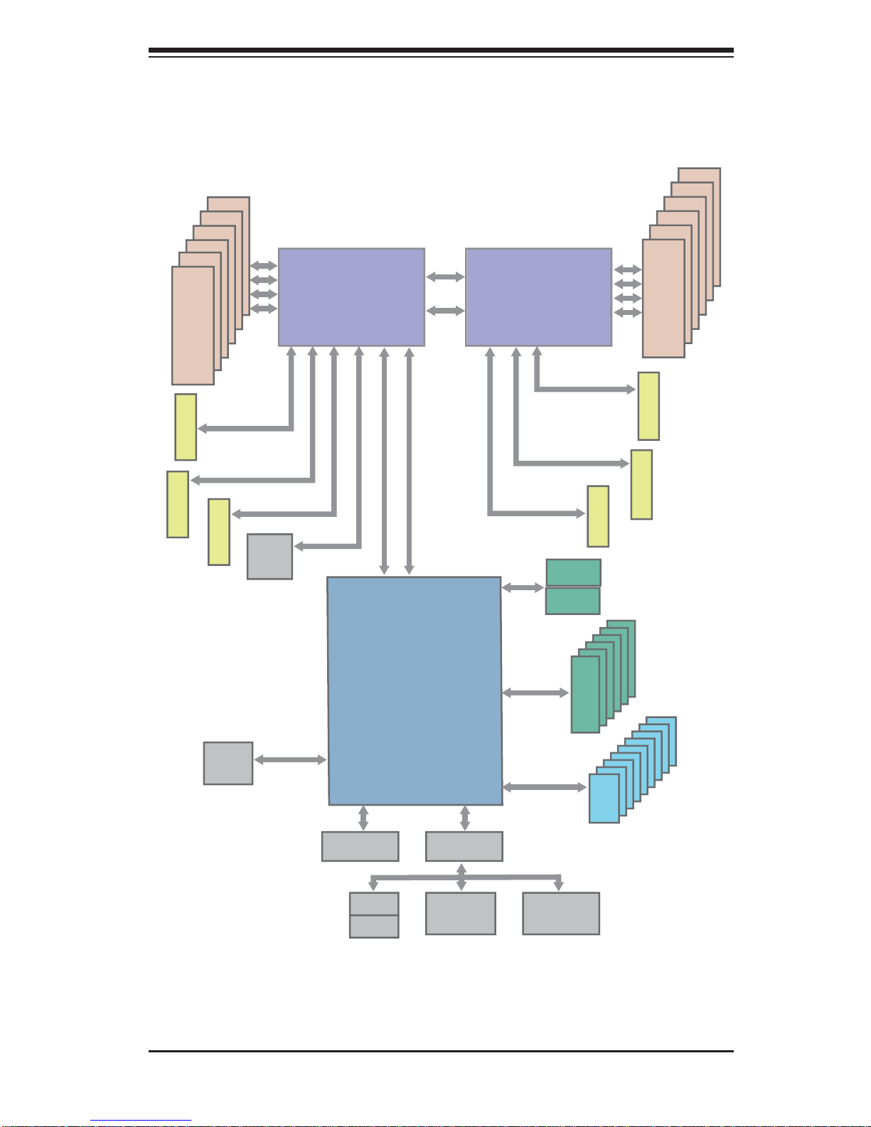
features of the X9DRi-F. (See Figure 1-1 for a block diagram of the chipset).
Processors
The X9DRi-F supports single or dual E5-2600 Series processors in Socket R LGA201 1
type sockets. Please refer to our web site for a complete listing of supported
processors (www.supermicro.com).
Memory
The X9DRi-F has sixteen (16) single/dual/tri/quad channel 240-pin DIMM sockets
that can support up to 512 GB of DDR3 1600/1333/1066/800 MHz speed
registered ECC SDRAM in two-channel memory bus. Memory sizes of
1GB, 2GB, 4GB, 8GB, 16GB and 32GB @ 1.35V/1.5V voltages are supported.
Please refer to Chapter 5 for installing memory.
Serial ATA
An on -c hip (PCH C606) SATA contro ller is i ntegrate d into theX9 DRi - F to provi de
a six-po rt, 3 Gb/se c SATA subsystem, wh ich is RA ID 0, 1, 5 and 10 supported.
The SATA drives ar e hot-s wappab le units .
Note: You must have RAID set up to enable the hot-swap capability of the SATA
drives. D ocum entati on on R AI D setup gui deline s can be fo und on our we b site.
Onboard Controllers/Ports
The color-coded I/O ports on the X9DRi-F include two COM ports (one header and
one port), a VGA (monitor) port, eleven USB 2.0 ports (4x rear, 6x header, 1x type
A), PS/2 mouse and keyboard ports, two gigabit Ethernet ports and one dedicated
IPMI LAN port.
Note 1: For more information on IPMI confi guration, please refer to the IPMI User's
Guide posted on our website at http://www.supermicro.com/support/manuals/
Graphics Controller
The X9DRi-F features an integrated Nuvoton WP450R BMC Base-board Controller
(BMC) chip, which also acts as a video controller..

Chapter 1: Introduction
1-3
Other Features
Other onboard features that promote system health include onboard voltage
monitors, auto-switching voltage regulators, chassis and CPU overheat sensors,
power management, AC power loss recovery, virus protection and BIOS rescue.
1-3 Server Chassis Features
The 6027R-TRF is built upon the SC825TS-R740LPBP chassis. Details on the
chassis and on servicing procedures can be found in Chapter 6. The following is a
general outline of the main features of the chassis.
System Power
The SC825TS-R740LPBP features a redundant 740 Watt power supply consisting
of two power modules. The system does not need to be shut down when replacing
or removing a single power supply module.
Hard Drive Subsystem
The SC825TS-R740LPBP chass is was de sign ed to sup por t e ight ho t-sw ap SATA
or SAS hard drives.
Note: A SAS UIO card must be installed to suppor t SAS drives - not included
with system.
PCI Expansion Slots
A riser card (RSC-R2UU-UA3E8+) on the left side of the chassis can support a
AOC-PG-i2+ add-on card to provide two additional Gb LAN ports. Alternately, this
slot can instead support either a UIO card, one PCI-E x16 card, or four SAS/SATA
drives with an optional UIO SAS card. See our web site for details (http://www.
supermicro.com/products/nfo/UIO.cfm). See section 5-6 for further details.)
Front Control Panel
The control panel on the SUPERSERVER 6027R-TRF provides you with system
monitoring and control. LEDs indicate system power, HDD activity, network activity,
system overheat and power supply failure. A main power button and a system reset
button are also included. In addition, two USB ports have been incorporated into
the control panel to provide front side USB access.
1-4
SUPERSERVER 6027R-TRF USER'S MANUAL
I/O Backplane
The SC825TS-R740LPBP is an ATX form factor chassis designed to be used in a
2U rackmount confi guration. The I/O backplane provides four standard-size add-on
card slots, one COM port, a VGA port, two USB 2.0 ports, PS/2 mouse and keyboard
ports, a dedicated IPMI LAN port and two gigabit Ethernet ports.
Cooling System
The SC825TS-R740LPBP chassis has an innovative cooling design that includes
three 8-cm hot-plug system cooling fans located in the middle section of the chassis.
An air shroud channels the airfl ow from the system fans to effi ciently cool the
processor area of the system. The power supply module also includes a cooling fan.
1-4 Advanced Power Management (for -F Models Only)
Intel® Intelligent Power Node Manager (NM)
The Intel® Intelligent Power Node Manager (IPNM) provides your system with
real-time thermal control and power management for maximum energy effi ciency.
Although IPNM Specifi cation Version 1.5 is supported by the BMC (Baseboard
Management Controller), your system must also have IPNM-compatible
Manageability Engine (ME) fi rmware installed to use this feature.
Manageability Engine (ME)
The Manageability Engine, which is an ARC controller embedded in the IOH (I/O
Hub), provides Server Platform Services (SPS) to your system. The services
provided by SPS are different from those proveded by the ME on client platforms.
Chapter 1: Introduction
1-5
Figure 1-1. Intel PCH C602/C606 Chipset:
System Block Diagram
Note: This is a general block diagram. Please see Chapter 5 for details.
SLOT 2
KB
MS
COM1
External
#0-5
#0-6
Ports 4~7
Ports 0~3
800/1066/1333
#0-4
#0-3
#0-2
#0-1
DDR3
#1-4
#1-3
800/1066/1333
#1-2
#1-1
DDR3
QPI
QPI
8G
LANE6
SLOT 1
COM2
Header
SLOT 3
PCI-E X8
USB 2.0
3.0 Gb/S
PCH C602/C606
PCI-E X16 G3
DMI2
LANE5
LANE1/2/3/4
SPI
P0
SIO
W83527
USB
SATA
2 Rear
4 Front
1 Type-A
BMC
PCI-E X8 G3
PCI-32
#1-5
#1-6
PCI-E X8 G3
SAS
8 SNB CORE
DDR3
QPI
8G
SAS
SAS
P1
P1
P0
PCI-E X4 G3
8 SNB CORE
DDR3
E5-2600 Series
Processor
E5-2600 Series
Processor
SLOT 4
SLOT 5
PCI-E X16
PCI-E X16
PCI-E X16
SLOT 6
PCI-E X8
PCI-E X8 G3
PCI-E X16 G3
PCI-E X16 G3
6.0 Gb/S
FOR PORT 0/1
PCI-E X8
82580
LAN
VGA
PCI-E X4
#2
#3A
#3B
#1B
#1A
DMI2
DMI2
#2
#1
#3
DMI2 4GB/s
8GB/s
#0~#6
#0~#8

1-6
SUPERSERVER 6027R-TRF USER'S MANUAL
1-5 Contacting Supermicro
Headquarters
Address: Super Micro Computer, Inc.
980 Rock Ave.
San Jose, CA 95131 U.S.A.
Tel: +1 (408) 503-8000
Fax: +1 (408) 503-8008
Email: marketing@supermicro.com (General Information)
support@supermicro.com (Technical Support)
Web Site: www.supermicro.com
Europe
Address: Super Micro Computer B.V.
Het Sterrenbeeld 28, 5215 ML
's-Hertogenbosch, The Netherlands
Tel: +31 (0) 73-6400390
Fax: +31 (0) 73-6416525
Email: sales@supermicro.nl (General Information)
support@supermicro.nl (Technical Support)
rma@supermicro.nl (Customer Support)
Asia-Pacifi c
Address: Super Micro Computer, Inc.
4F, No. 232-1, Liancheng Rd.
Chung-Ho 235, Taipei County
Taiwan, R.O.C.
Tel: +886-(2) 8226-3990
Fax: +886-(2) 8226-3991
Web Site: www.supermicro.com.tw
Technical Support:
Email: support@supermicro.com.tw
Tel: +886-(2) 8226-5990
Chapter 2: Server Installation
2-1
Chapter 2
Server Installation
2-1 Overview
This chapter provides a quick setup checklist to get your SUPERSERVER
6027R-TRF up and running. Following these steps in the order given should enable
you to have the system operational within a minimum amount of time. This quick
setup assumes that your system has come to you with the processors and memory
preinstalled. If your system is not already fully integrated with a serverboard,
processors, system memory etc., please turn to the chapter or section noted in
each step for details on installing specifi c components.
2-2 Unpacking the System
You should inspect the box the SUPERSERVER 6027R-TRF was shipped in and
note if it was damaged in any way. If the server itself shows damage you should
fi le a damage claim with the carrier who delivered it.
Decide on a suitable location for the rack unit that will hold the SUPERSERVER
6027R-TRF. It should be situated in a clean, dust-free area that is well ventilated.
Avoid areas where heat, electrical noise and electromagnetic fi elds are generated.
You will also need it placed near a grounded power outlet. Read the Rack and
Server Precautions in the next section.
2-3 Preparing for Setup
The box the SUPERSERVER 6027R-TRF was shipped in should include two
sets of rail assemblies, two rail mounting brackets and the mounting screws you
will need to install the system into the rack. Follow the steps in the order given to
complete the installation process in a minimum amount of time. Please read this
section in its entirety before you begin the installation procedure outlined in the
sections that follow.
Choosing a Setup Location
• Leave enough clearance in front of the rack to enable you to open the front door
completely (~25 inches) and approximately 30 inches of clearance in the back
of the rack to allow for suffi cient airfl ow and ease in servicing.
2-2
SUPERSERVER 6027R-TRF USER'S MANUAL
• This product is for installation only in a Restricted Access Location (dedicated
equipment rooms, service closets and the like).
• This product is not suitable for use with visual display work place devices
acccording to §2 of the the German Ordinance for Work with Visual Display
Units.
!
!
Warnings and Precautions!
Rack Precautions
• Ensure that the leveling jacks on the bottom of the rack are fully extended to
the fl oor with the full weight of the rack resting on them.
• In single rack installation, stabilizers should be attached to the rack. In multiple
rack installations, the racks should be coupled together.
• Always make sure the rack is stable before extending a component from the
rack.
• You should extend only one component at a time - extending two or more si-
multaneously may cause the rack to become unstable.
Server Precautions
• Review the electrical and general safety precautions in Chapter 4.
• Determine the placement of each component in the rack before you install the
rails.
• Install the heaviest server components on the bottom of the rack fi rst, and then
work up.
• Use a regulating uninterruptible power supply (UPS) to protect the server from
power surges, voltage spikes and to keep your system operating in case of a
power failure.
• Allow any hot plug drives and power supply modules to cool before touching
them.
• Always keep the rack's front door and all panels and components on the servers
closed when not servicing to maintain proper cooling.
Chapter 2: Server Installation
2-3
Rack Mounting Considerations
Ambient Operating Temperature
If installed in a closed or multi-unit rack assembly, the ambient operating
temperature of the rack environment may be greater than the ambient temperature
of the room. Therefore, consideration should be given to installing the equipment
in an environment compatible with the manufacturer’s maximum rated ambient
temperature (Tmra).
Reduced Airfl ow
Equipment should be mounted into a rack so that the amount of airfl ow required
for safe operation is not compromised.
Mechanical Loading
Equipment should be mounted into a rack so that a hazardous condition does not
arise due to uneven mechanical loading.
Circuit Overloading
Consideration should be given to the connection of the equipment to the power
supply circuitry and the effect that any possible overloading of circuits might have
on overcurrent protection and power supply wiring. Appropriate consideration of
equipment nameplate ratings should be used when addressing this concern.
Reliable Ground
A reliable ground must be maintained at all times. To ensure this, the rack
itself should be grounded. Particular attention should be given to power supply
connections other than the direct connections to the branch circuit (i.e. the use of
power strips, etc.).
2-4
SUPERSERVER 6027R-TRF USER'S MANUAL
2-4 Installing the System into a Rack
This section provides information on installing the SC825 chassis into a rack unit
with the quick-release rails provided. There are a variety of rack units on the market,
which may mean the assembly procedure will differ slightly. You should also refer to
the installation instructions that came with the rack unit you are using.
Note: This rail will fi t a rack between 26" and 33.5" deep.
Separating the Sections of the Rack Rails
The chassis package includes two rail assemblies in the rack mounting kit. Each
assembly consists of two sections: an inner fi xed chassis rail that secures directly
to the server chassis and an outer fi xed rack rail that secures directly to the rack
itself.
Installing the Inner Rail Extension
The SC825 chassis includes a set of inner rails in two sections: inner rails and inner
rail extensions. The inner rails are pre-attached to the chassis, and do not interfere
with normal use of the chassis if you decide not to use a server rack. The inner rail
extension is attached to the inner rail to mount the chassis in the rack.
Installing the Inner Rails
1. Place the inner rail extensions on the side of the chassis aligning the hooks
of the chassis with the rail extension holes. Make sure the extension faces
"outward" just like the pre-attached inner rail.
2. Slide the extension toward the front of the chassis.
3. Secure the chassis with 2 screws as illustrated. Repeat steps for the other
inner rail extension.
Chapter 2: Server Installation
2-5
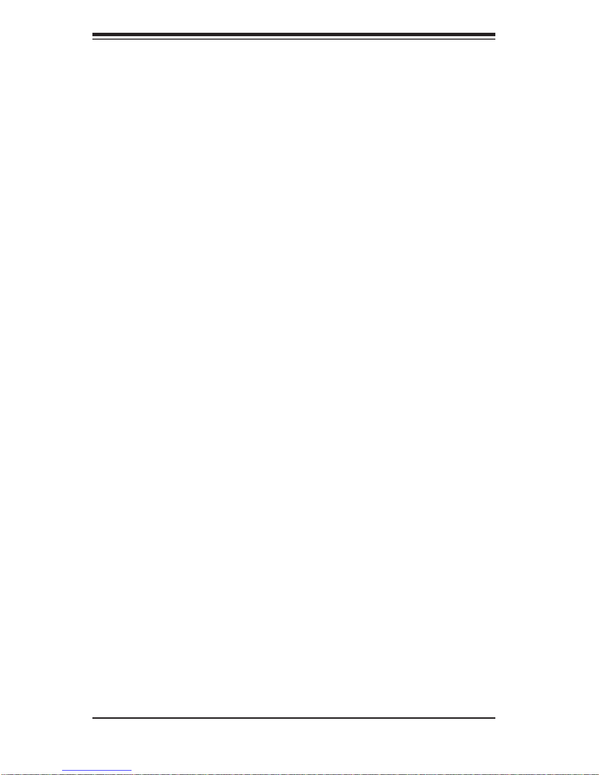
Figure 2-1: Separating the Rack Rails
Separating the Inner and Outer
Rails
1. Locate the rail assembly in the
chassis packaging.
2. Extend the rail assembly by
pulling it outward.
3. Press the quick-release tab.
4. Separate the inner rail
extension from the outer rail
assembly.
1
1
1
2
1
4
1
3
Rail Assembly
Extending the Rails
Quick-Release Tab
Separating
the Inner Rail
Extension
2-6
SUPERSERVER 6027R-TRF USER'S MANUAL
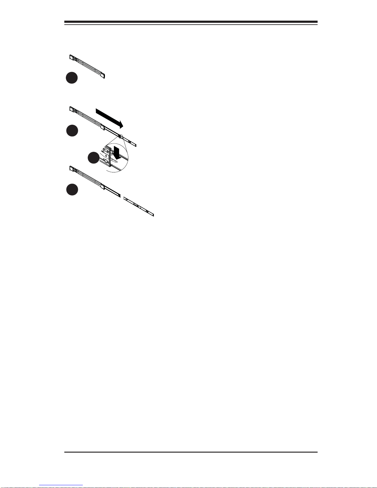
Outer Rack Rails
Outer rails attach to the rack and hold the chassis in place. The outer rails for the
SC825 chassis extend between 30 inches and 33 inches.
Installing the Outer Rails to the Rack
1. Secure the back end of the outer rail to the rack, using the screws provided.
2. Press the button where the two outer rails are joined to retract the smaller
outer rail.
3. Hang the hooks of the rails onto the rack holes and if desired, use screws to
secure the front of the outer rail onto the rack.
4. Repeat steps 1-3 for the remaining outer rail.
Figure 2-2. Assembling the Outer Rails
1
1
1
2
1
3
Chapter 2: Server Installation
2-7
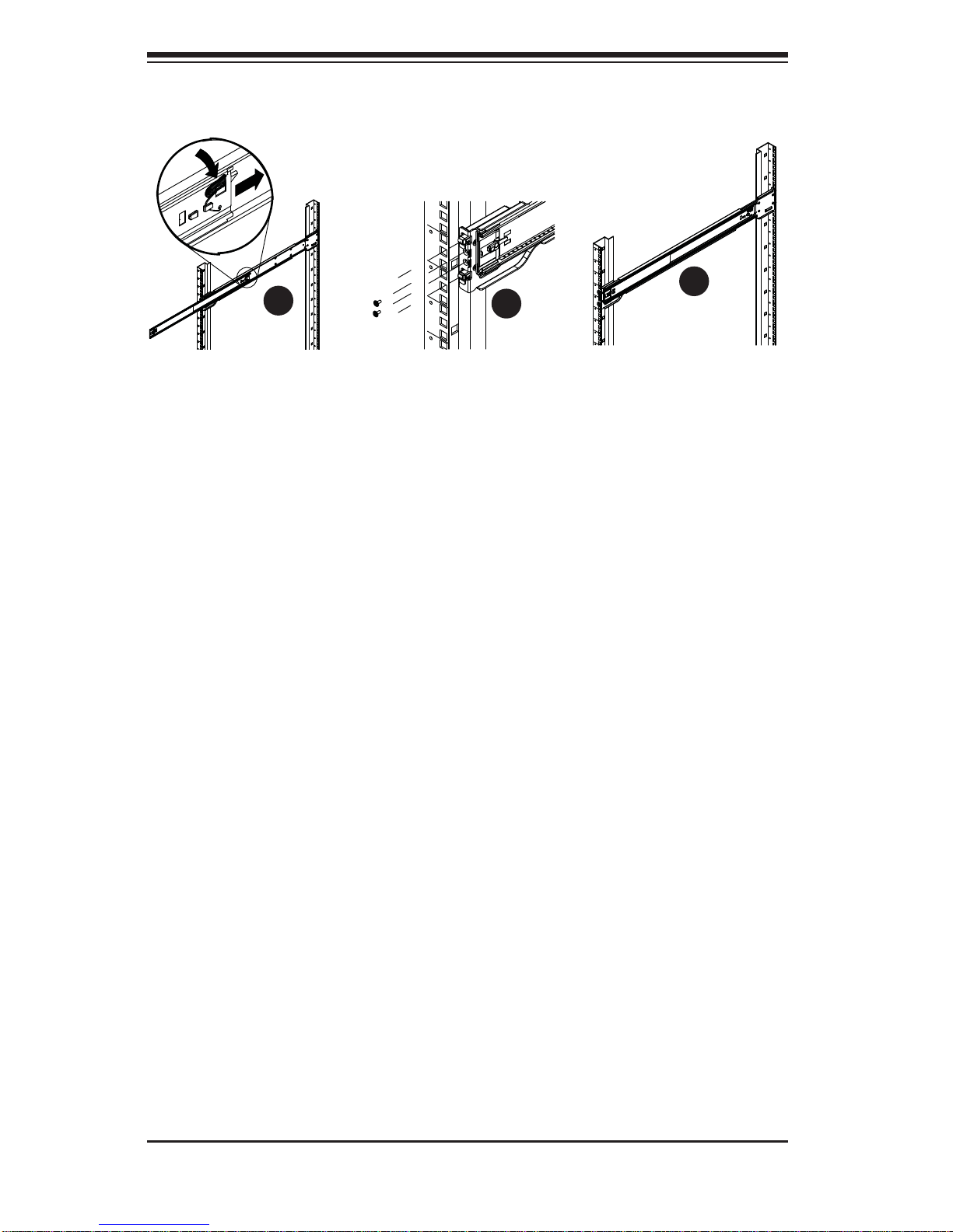
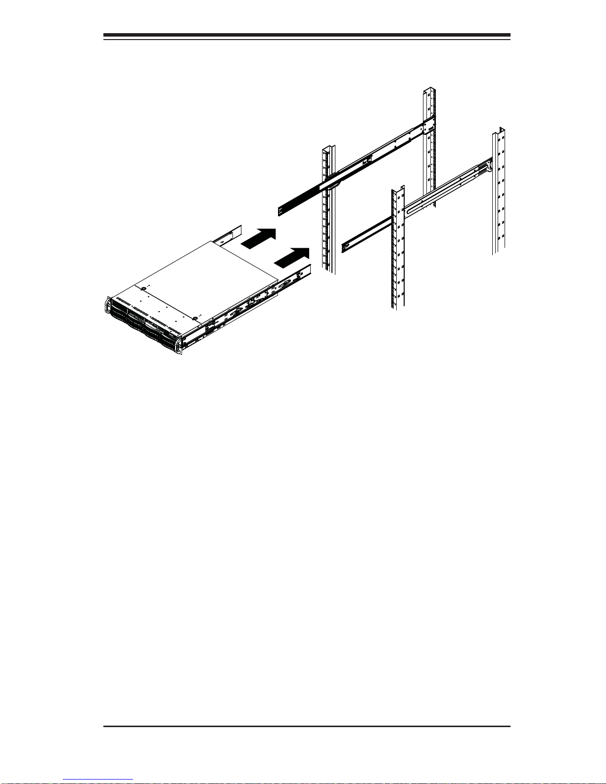
Figure 2-3. Installing the Rack Rails
Installing the Chassis into a Rack
1. Extend the outer rails as illustrated above.
2. Align the inner rails of the chassis with the outer rails on the rack.
3. Slide the inner rails into the outer rails, keeping the pressure even on both
sides. When the chassis has been pushed completely into the rack, it should
click into the locked position.
4. Optional screws may be used to secure the to hold the front of the chassis to
the rack.
2-8
SUPERSERVER 6027R-TRF USER'S MANUAL
2-5 Checking the Serverboard Setup
After you install the 6027R-TRF in the rack, you will need to open the unit to make
sure the serverboard is properly installed and all the connections have been made.
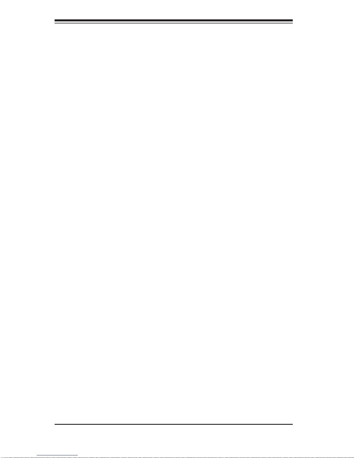
Accessing the inside of the System
1. First, grasp the two handles on either side and pull the unit straight out until it
locks (you will hear a "click").
2. Next, depress the two buttons on the top of the chassis to release the top
cover.
3. You can then lift the top cover from the chassis to gain full access to the
inside of the server.
Checking the Components and Setup
1. You may have one or two processors already installed into the serverboard.
Each processor needs its own heat sink. See Chapter 5 for instructions on
processor and heat sink installation.
2. Your 6027R-TRF server system may have come with system memory already
installed. Make sure all DIMMs are fully seated in their slots. For details on
adding system memory, refer to Chapter 5.
3. If desired, you can install add-on cards to the system. See Chapter 5 for
details on installing PCI add-on cards.
4. Make sure all power and data cables are properly connected and not blocking
the chassis airfl ow. Also make sure that no cables are positioned in front of
the fans. See Chapter 5 for details on cable connections.
Chapter 2: Server Installation
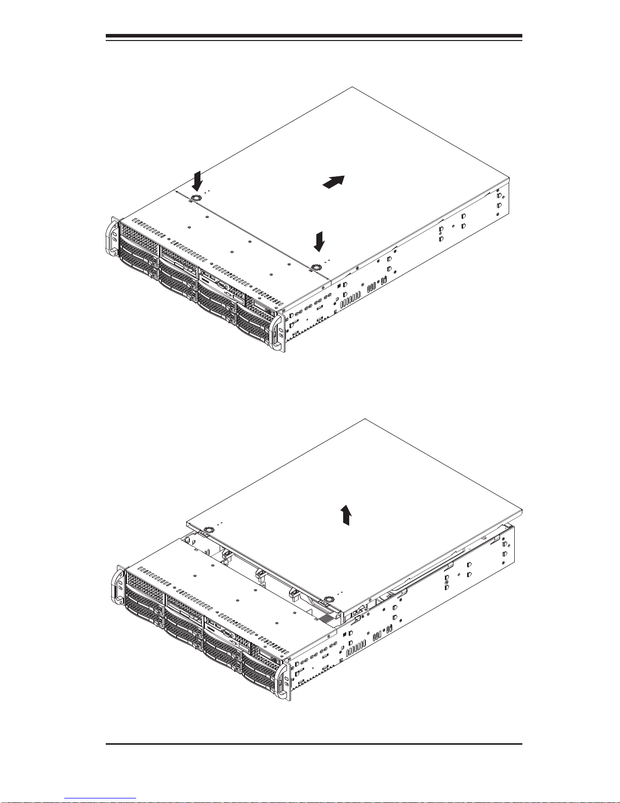
2-9
Figure 2-3. Accessing the Inside of the System
2-10
SUPERSERVER 6027R-TRF USER'S MANUAL
2-6 Checking the Drive Bay Setup
Next, you should check to make sure the peripheral drives and the SAS/SA TA drives
have been properly installed and all connections have been made.
Checking the Drives
1. All drives are accessable from the front of the server. For servicing the DVDROM, you will need to remove the top chassis cover. The hard drives can be
installed and removed from the front of the chassis without removing the top
chassis cover.
2. A slim DVD-ROM may be preinstalled in your server. Refer to Chapter 6 if
you need to install a DVD-ROM drive to the system.
3. Depending upon your system's confi guration, your system may have one or
more drives already installed. If you need to install hard drives, please refer to
Chapter 6.
Checking the Airfl ow
1. Airfl ow is provided by three hot-swappable 8-cm chassis cooling fans. The
system component layout was carefully designed to direct suffi cient cooling
airfl ow to the components that generate the most heat.
2. Note that all power and data cables have been routed in such a way that they
do not block the airfl ow generated by the fans.
Providing Power
1. Plug the power cord(s) from the power supply unit(s) into a high-quality
power strip that offers protection from electrical noise and power surges. It is
recommended that you use an uninterruptible power supply (UPS).
2. Depress the power on button on the front of the chassis.
Chapter 3: System Interface
3-1
Chapter 3
System Interface
3-1 Overview
There are several LEDs on the control panel of the 6027R-TRF server as well as
others on the drive carriers to keep you constantly informed of the overall status
of the system as well as the activity and health of specifi c components. There are
also two buttons on the chassis control panel.
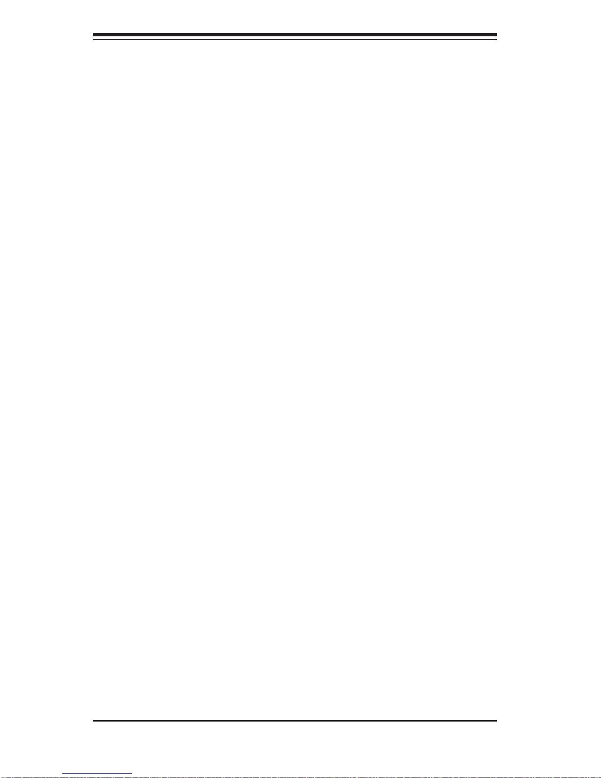
3-2 Control Panel Buttons
There are two buttons located on the front of the chassis: a reset button and a
power on/off button.
Reset
Use the reset button to reboot the system.
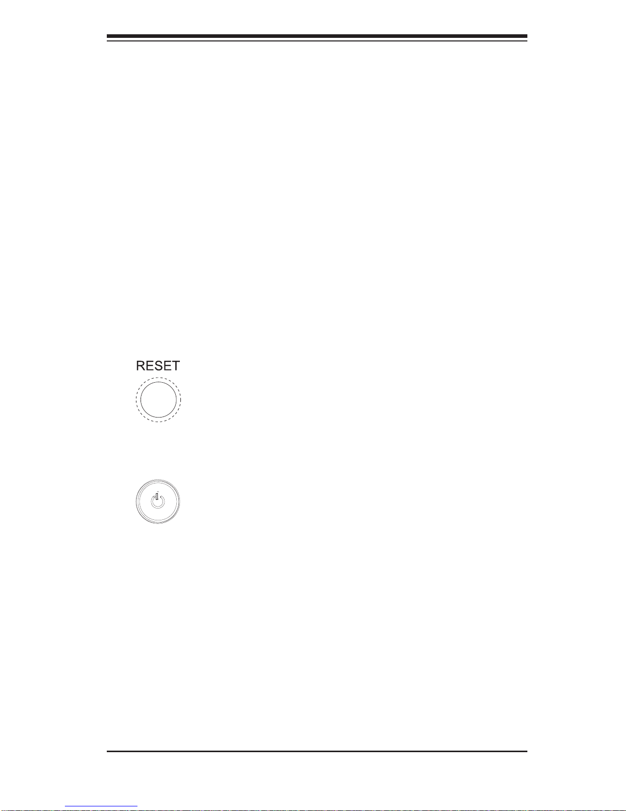
Power
This is the main power button, which is used to apply or turn off the main system
power. T urning off system power with this button removes the main power but keeps
standby power supplied to the system.
SUPERSERVER 6027R-TRF USER'S MANUAL
3-2
1
2
3-3 Control Panel LEDs
The control panel located on the front of the chassis has several LEDs. These
LEDs provide you with critical information related to different parts of the system.
This section explains what each LED indicates when illuminated and any corrective
action you may need to take.
Power Fail
Indicates a power supply module has failed. The second power supply module will
take the load and keep the system running but the failed module will need to be
replaced. Refer to Chapter 6 for details on replacing the power supply. This LED
should be off when the system is operating normally.
Overheat/Fan Fail:
When this LED fl ashes, it indicates a fan failure. When on continuously it indicates
an overheat condition, which may be caused by cables obstructing the airfl ow in
the system or the ambient room temperature being too warm. Check the routing of
the cables and make sure all fans are present and operating normally. You should
also check to make sure that the chassis covers are installed. Finally, verify that
the heatsinks are installed properly (see Chapter 5). This LED will remain fl ashing
or on as long as the indicated condition exists.
NIC1
Indicates network activity on the LAN1 port when fl ashing.
NIC2
Indicates network activity on the LAN2 port when fl ashing.
Chapter 3: System Interface
3-3
HDD
On the SUPERSERVER 6027R-TRF, this LED indicates hard drive and/or DVDROM drive activity when fl ashing.
Power
Indicates power is being supplied to the system's power supply units. This LED
should normally be illuminated when the system is operating.
3-4 Drive Carrier LEDs
Each drive carrier has two LEDs:
SATA Drives
• Green: When ill uminated, the green LED on the SATA drive carr ier indic ates
drive ac tivity. A con nectio n to the SATA b ackplane e nables th is LED to blink
on and off when that particular drive is being accessed. Please refer to Chapter
6 for instructions on replacing failed SATA drives.
• Red: When this LED fl ashes it indicates the drive is rebuilding. When solid on
it indicates a SATA drive failure. If a drive fails, you should be notifi ed by your
system management software. Please refer to Chapter 6 for instructions on
replacing failed drives.
SAS Drives
• Green: When illuminated, the green LED on the drive carrier indicates the SAS
drive is powered on. If this LED is not lit, it means no power is being provided for
the dri ve. Please refer to Chapter 6 for instructions on replacing failed drives.
• Red: When this LED fl ashes it indicates the drive is rebuilding. When solid on
it indicates a SAS drive failure. If a drive fails, you should be notifi ed by your
system management software. Please refer to Chapter 6 for instructions on
replacing failed drives.
SUPERSERVER 6027R-TRF USER'S MANUAL
3-4
Notes
Chapter 4: System Safety
4-1
Chapter 4
System Safety
4-1 Electrical Safety Precautions
!
Basic electrical safety precautions should be followed to protect yourself from harm
and the SUPERSERVER 6027R-TRF from damage:
• Be aware of the locations of the power on/off switch on the chassis as well
as the room's emergency power-off switch, disconnection switch or electrical
outlet. If an electrical accident occurs, you can then quickly remove power from
the system.
• Do not work alone when working with high voltage components.
• Power should always be disconnected from the system when removing or in-
stalling main system components, such as the serverboard, memory modules
and fl oppy drive. When disconnecting power, you should fi rst power down the
operating system fi rst and then unplug the power cords. The unit has more than
one power supply cord. Disconnect two power supply cords before servicing to
avoid electrical shock.
• When working around exposed electrical circuits, another person who is familiar
with the power-off controls should be nearby to switch off the power if necessary.
• Use only one hand when working with powered-on electrical equipment. This
is to avoid making a complete circuit, which will cause electrical shock. Use
extreme caution when using metal tools, which can easily damage any electrical
components or circuit boards they come into contact with.
• Do not use mats designed to decrease static electrical discharge as protection
from electrical shock. Instead, use rubber mats that have been specifi cally
designed as electrical insulators.
• The power supply power cords must include a grounding plug and must be
plugged into grounded electrical outlets.
SUPERSERVER 6027R-TRF USER'S MANUAL
4-2
• This product may be connected to an IT power system. In all cases, make sure
that the unit is also reliably connected to Earth (ground).
• Serverboard Battery: CAUTION - There is a danger of explosion if the onboard
battery is installed upside down, which will reverse its polarites (see Figure
4-1). This battery must be replaced only with the same or an equivalent type
recommended by the manufacturer. Dispose of used batteries according to the
manufacturer's instructions.
• DVD-ROM Laser: CAUTION - this server may have come equipped with a
DVD-ROM drive. To prevent direct exposure to the laser beam and hazardous
radiation exposure, do not open the enclosure or use the unit in any unconventional way.
• Mainboard replaceable soldered-in fuses: Self-resetting PTC (Positive Tempera-
ture Coeffi cient) fuses on the mainboard must be replaced by trained service
technicians only. The new fuse must be the same or equivalent as the one
replaced. Contact technical support for details and support.
4-2 General Safety Precautions
!
Follow these rules to ensure general safety:
• Keep the area around the 2022G-URF clean and free of clutter.
• The 6027R-TRF weighs approximately 57 lbs. (25.85 kg.) when fully loaded.
When lifting the system, two people at either end should lift slowly with their
feet spread out to distribute the weight. Always keep your back straight and lift
with your legs.
• Place the chassis top cover and any system components that have been re-
moved away from the system or on a table so that they won't accidentally be
stepped on.
• While working on the system, do not wear loose clothing such as neckties and
unbuttoned shirt sleeves, which can come into contact with electrical circuits or
be pulled into a cooling fan.
 Loading...