

Supero SUPERSERVER 6017R-TDLF User Manual
SUPERSERVER
6017R-TDLF
SUPER
®
USER’S MANUAL
1.0

The information in this User’s Manual has been carefully reviewed and is believed to be accurate.
The vendor assumes no responsibility for any inaccuracies that may be contained in this document,
makes no commitment to update or to keep current the information in this manual, or to notify any
person or organization of the updates. Please Note: For the most up-to-date version of this
manual, please see our web site at
www.supermicro.com.
Super Micro Computer, Inc. ("Supermicro") reserves the right to make changes to the product
described in this manual at any time and without notice. This product, including software and documentation, is the property of Supermicro and/or its licensors, and is supplied only under a license.
Any use or reproduction of this product is not allowed, except as expressly permitted by the terms
of said license.
IN NO EVENT WILL SUPERMICRO BE LIABLE FOR DIRECT, INDIRECT, SPECIAL, INCIDENTAL,
SPECULATIVE OR CONSEQUENTIAL DAMAGES ARISING FROM THE USE OR INABILITY TO
USE THIS PRODUCT OR DOCUMENTATION, EVEN IF ADVISED OF THE POSSIBILITY OF
SUCH DAMAGES. IN PARTICULAR, SUPERMICRO SHALL NOT HAVE LIABILITY FOR ANY
HARDWARE, SOFTW ARE, OR DA TA STORED OR USED WITH THE PRODUCT, INCLUDING THE
COSTS OF REPAIRING, REPLACING, INTEGRATING, INSTALLING OR RECOVERING SUCH
HARDWARE, SOFTWARE, OR DATA.
Any disputes arising between manufacturer and customer shall be governed by the laws of Santa
Clara County in the State of California, USA. The State of California, County of Santa Clara shall
be the exclusive venue for the resolution of any such disputes. Super Micro's total liability for all
claims will not exceed the price paid for the hardware product.
FCC Statement: This equipment has been tested and found to comply with the limits for a Class A
digital device pursuant to Part 15 of the FCC Rules. These limits are designed to provide reasonable
protection against harmful interference when the equipment is operated in a commercial environment. This equipment generates, uses, and can radiate radio frequency energy and, if not installed
and used in accordance with the manufacturer’s instruction manual, may cause harmful interference
with radio communications. Operation of this equipment in a residential area is likely to cause harmful
interference, in which case you will be required to correct the interference at your own expense.
California Best Management Practices Regulations for Perchlorate Materials: This Perchlorate warning applies only to products containing CR (Manganese Dioxide) Lithium coin cells. “Perchlorate
Material-special handling may apply. See
www.dtsc.ca.gov/hazardouswaste/perchlorate”
WARNING: Handling of lead solder materials used in this
product may expose you to lead, a chemical known to the
State of California to cause birth defects and other reproductive harm.
Manual Revision 1.0
Release Date: April 29, 2013
Unless you request and receive written permission from Super Micro Computer, Inc., you may not
copy any part of this document.
Information in this document is subject to change without notice. Other products and companies
referred to herein are trademarks or registered trademarks of their respective companies or mark
holders.
Copyright © 2013 by Super Micro Computer, Inc.
All rights reserved.
Printed in the United States of America
iii
Preface
Preface
About This Manual
This manual is written for professional system integrators and PC technicians. It
provides information for the installation and use of the SuperServer 6017R-TDLF.
Installation and maintenance should be performed by experienced technicians only .
The SuperServer 6017R-TDLF is a high-end server based on the SC813LT-350CB
1U rackmount chassis and the Super X9DRD-LF serverboard.
Manual Organization
Chapter 1: Introduction
The fi rst chapter provides a checklist of the main components included with the
server system and describes the main features of the X9DRD-LF serverboard and
the SC813LT-350CB chassis.
Chapter 2: Server Installation
This chapter describes the steps necessary to install the SuperServer 6017R-TDLF
into a rack and check out the server confi guration prior to powering up the system.
If your server was ordered without processor and memory components, this chapter
will refer you to the appropriate sections of the manual for their installation.
Chapter 3: System Interface
Refer here for details on the system interface, which includes the functions and
information provided by the control panel on the chassis as well as other LEDs
located throughout the system.
Chapter 4: Standardized Warning Statements
You should thoroughly familiarize yourself with this chapter for a general overview
of safety precautions that should be followed when installing and servicing the
SuperServer 6017R-TDLF.

SUPERSERVER 6017R-TDLF User's Manual
iv
Chapter 5: Advanced Serverboard Setup
Chapter 5 provides detailed information on the X9DRD-LF serverboard, including the
locations and functions of connections, headers and jumpers. Refer to this chapter
when adding or removing processors or main memory and when reconfi guring the
serverboard.
Chapter 6: Advanced Chassis Setup
Refer to Chapter 6 for detailed information on the SC813LT-350CB server chassis.
You should follow the procedures given in this chapter when installing, removing or
reconfi guring SATA or peripheral drives and when replacing system power supply
modules and cooling fans.
Chapter 7: BIOS
The BIOS chapter includes an introduction to BIOS and provides detailed information on running the CMOS Setup Utility.
Appendix A: BIOS Error Beep Codes
Appendix B: System Specifi cations

v
Preface
Notes

vi
Table of Contents
Chapter 1 Introduction
1-1 Overview .........................................................................................................1-1
1-2 Serverboard Features .....................................................................................1-2
Processors ......................................................................................................1-2
Memory ...........................................................................................................1-2
SATA ................................................................................................................ 1-2
I/O Ports .......................................................................................................... 1-2
PCI Expansion Slots ....................................................................................... 1-2
Onboard Graphics ...........................................................................................1-2
1-3 Server Chassis Features ................................................................................1-3
System Power ................................................................................................. 1-3
SATA Subsystem .............................................................................................1-3
Control Panel .................................................................................................. 1-3
Cooling System ............................................................................................... 1-3
1-4 Contacting Supermicro ....................................................................................1-5
Chapter 2 Server Installation
2-1 Overview .........................................................................................................2-1
2-2 Unpacking the System .................................................................................... 2-1
2-3 Preparing for Setup .........................................................................................2-1
Choosing a Setup Location ............................................................................. 2-2
2-4 Warnings and Precautions .............................................................................. 2-2
Rack Precautions ............................................................................................ 2-2
Server Precautions .......................................................................................... 2-2
Rack Mounting Considerations .......................................................................2-3
Ambient Operating Temperature ................................................................ 2-3
Reduced Airfl ow .........................................................................................2-3
Mechanical Loading ................................................................................... 2-3
Circuit Overloading .....................................................................................2-3
Reliable Ground ......................................................................................... 2-3
2-5 Rack Mounting Instructions ............................................................................. 2-4
Identifying the Sections of the Rack Rails ...................................................... 2-4
Installing the Chassis into a Telco rack .......................................................... 2-8
Chapter 3 System Interface
3-1 Overview .........................................................................................................3-1
3-2 Control Panel Buttons ..................................................................................... 3-1
Reset ...............................................................................................................3-1
Power ..............................................................................................................3-1
SUPERSERVER 6017R-TDLF User's Manual
vii
Table of Contents
3-3 Control Panel LEDs ........................................................................................3-2
Information LED ..............................................................................................3-2
NIC1 ................................................................................................................3-2
NIC2 ................................................................................................................3-2
HDD .................................................................................................................3-2
Power ..............................................................................................................3-3
3-4 Hard Drive Carrier LEDs ................................................................................. 3-3
Chapter 4 Standardized Warning Statements for AC Systems
4-1 About Standardized Warning Statements .......................................................4-1
Warning Defi nition ...........................................................................................4-1
Installation Instructions .................................................................................... 4-4
Circuit Breaker ................................................................................................ 4-5
Power Disconnection Warning ........................................................................ 4-6
Equipment Installation .....................................................................................4-8
Restricted Area ................................................................................................4-9
Battery Handling ............................................................................................ 4-10
Redundant Power Supplies ..........................................................................4-12
Backplane Voltage ........................................................................................ 4-13
Comply with Local and National Electrical Codes ........................................ 4-14
Product Disposal ........................................................................................... 4-15
Hot Swap Fan Warning ................................................................................. 4-16
Power Cable and AC Adapter ......................................................................4-18
Chapter 5 Advanced Serverboard Setup
5-1 Handling the Serverboard ............................................................................... 5-1
Precautions .....................................................................................................5-1
Unpacking .......................................................................................................5-1
5-2 Processor and Heatsink Installation................................................................5-2
Installing an LGA 2011 Processor ................................................................... 5-2
Installing a Passive CPU Heatsink ................................................................. 5-5
Removing the Heatsink ................................................................................... 5-5
5-3 Connecting Cables .......................................................................................... 5-6
Connecting Data Cables ................................................................................. 5-6
Connecting Power Cables ..............................................................................5-6
Connecting the Control Panel ......................................................................... 5-6
5-4 I/O Ports ..........................................................................................................5-7
5-5 Installing Memory ............................................................................................ 5-8
5-6 Adding PCI Cards ........................................................................................... 5-9
5-7 Serverboard Details ...................................................................................... 5-10
5-8 Connector Defi nitions ................................................................................... 5-12
viii
5-9 Jumper Settings ............................................................................................5-18
Explanation of Jumpers ................................................................................5-18
5-10 Onboard Indicators ........................................................................................5-20
5-11 SATA Drive Ports ........................................................................................... 5-21
5-12 Installing Software ......................................................................................... 5-22
SuperDoctor III .............................................................................................. 5-23
5-13 Onboard Battery ............................................................................................ 5-25
Chapter 6 Advanced Chassis Setup
6-1 Static-Sensitive Devices ..................................................................................6-1
Precautions .....................................................................................................6-1
6-2 Control Panel ..................................................................................................6-2
6-3 System Fans ...................................................................................................6-3
System Fan Failure .........................................................................................6-3
6-4 Drive Bay Installation/Removal .......................................................................6-5
Removing the Front Bezel .............................................................................. 6-5
Accessing the Drive Bays ...............................................................................6-5
SATA Drive Installation ....................................................................................6-6
SATA Power Cables ...................................................................................6-7
SATA Backplane ......................................................................................... 6-7
CD-ROM Drive Installation .............................................................................. 6-8
6-5 Power Supply .................................................................................................. 6-9
Power Supply Fail ........................................................................................... 6-9
Chapter 7 BIOS
7-1 Introduction ...................................................................................................... 7-1
Starting BIOS Setup Utility .............................................................................. 7-1
How To Change the Confi guration Data .........................................................7-1
Starting the Setup Utility ................................................................................. 7-2
7-2 Main Setup ...................................................................................................... 7-2
7-3 Advanced Setup Confi gurations......................................................................7-4
7-4 Event Logs .................................................................................................... 7-23
7-5 IPMI ............................................................................................................... 7-25
7-6 Boot ............................................................................................................... 7-27
7-7 Secur ity ......................................................................................................... 7-28
7-8 Save & Exit ................................................................................................... 7-29
Appendix A BIOS Error Beep Codes
Appendix B System Specifi cations
SUPERSERVER 6017R-TDLF User's Manual
Chapter 1
Introduction
1-1 Overview
The SuperServer 6017R-TDLF is a high-end server comprised of two main subsystems: the SC813LT-350CB 1U chassis and the X9DRD-LF serverboard. Please
refer to our web site for information on operating systems that have been certifi ed
for use with the system (www.supermicro.com).
In addition to the serverboard and chassis, various hardware components have
been included with the 6017R-TDLF, as listed below:
• Two 10-cm blower fans (FAN-0135L4)
• Two passive CPU heatsinks (SNK-P0047PS)
• SATA Accessories
One SATA backplane (BPN-SAS-813LT-O-P)
Four 3.5" hard drive carriers (MCP-220-00075-0B)
Two SATA Cables (CBL-0226L)
• One rackmount kit (MCP-290-00106-0N, MCP-290-00102-0N)
• SuperServer 6017R-TDLF Quick Reference Guide
Optional Parts:
• One RSC-RR1U-E16 riser card
• One Riser Card Bracket (MCP-120-00031-0N)
Note: a complete list of safety warnings is provided on the Supermicro web site at
http://www.supermicro.com/about/policies/safety_information.cfm
Chapter 1: Introduction
1-1

1-2
SUPERSERVER 6017R-TDLF User's Manual
1-2 Serverboard Features
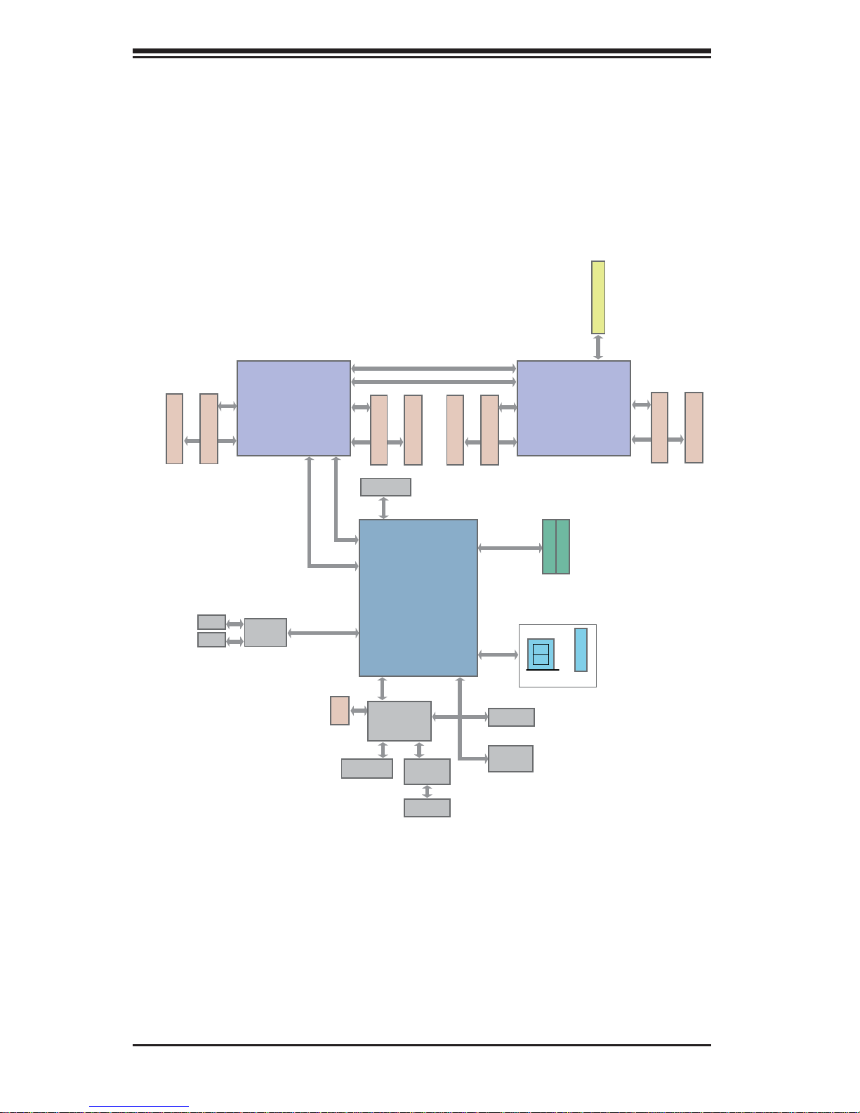
At the heart of the SuperServer 6017R-TDLF lies the X9DRD-LF, a dual processor
serverboard based on Intel's C602A chipset. Below are the main features of the
X9DRD-LF (see Figure 1-1 for a block diagram of the chipset).
Processors
The X9DRD-LF supports single or dual Intel® Xeon® E5-2600 Series processors in
LGA 2011 sockets. Please refer to the serverboard description pages on our web
site for a complete listing of supported processors.
Memory
The X9DRD-LF has 8 DIMM sockets that can support up to 256GB of DDR31600 /1333/1066 /80 0 reg istere d (RDI MM), Loa d Reduc ed (LRD IMM) EC C or Un buf fere d (U DI MM) EC C/no n - ECC me mo r y. Please refer to Chapter 5 for installing
memory.
SATA
An on-chip SATA controller is integrated into the X9DRD-LF to provide a two-port,
Serial ATA subsystem, which is RAID 0 and 1 supported. The SATA drives are
hot-swappable units.
I/O Ports
The color-coded I/O ports include one COM port, a VGA (monitor) port, two USB
2.0 ports and two gigabit Ethernet ports. A dedicated IPMI LAN port is also included.
PCI Expansion Slots
The X9DRD-LF features one PCI-E 3.0 x16 expansion slots.
Onboard Graphics
The X9DRD-LF provides onboard grpahics with a Matrox G200eW graphics controller.

1-3
Chapter 1: Introduction
1-3 Server Chassis Features
The following is a general outline of the main features of the SC813LT-350CB
chassis.
System Power
The 6017R-TDLF (SC813LT-350CB) includes a single 350W power supply. See
Chapter 6 for details.
SATA Subsystem
For the 6017R-TDLF, the SC813LT- 350C B chassi s was design ed to suppor t t wo
SATA har d drive s, whic h are hot -swap pable un its.
Control Panel
The SC813LT-350CB's control panel provides important system monitoring and
control information. LEDs indicate power on, network activity, hard disk drive activity and system overheat conditions. The control panel also includes a main power
button and a system reset button.
Cooling System
The SC813LT-350CB chassis has an innovative cooling design that features two
10-cm high-performance blower fans (see web site for details). Each of these fans
plug into a fan header on the serverboard.
Fan speed is determined by system temperature via IPMI.
1-4
SUPERSERVER 6017R-TDLF User's Manual
Figure 1-1. Intel C602A Chipset:
System Block Diagram
Note: This is a general block diagram. Please see Chapter 5 for details.
E5-2600
DDR3 DIMM
DDR3 DIMM
#1
D
C
#1
DDR3 DIMM
DDR3 DIMM
#1
A
#1
PE3
PE2
A,B A,B C,D A,B C,D
PE2 PE2 PE3 PE3
CPU0 LEFT
PE2 DMI
DMI
PET [1~4]
PEG0 [0..3]
x4 (Lane 1~4)
SATA GEN 3
LPC
USB
USB
PET8
P0
P1
B
E5-2600
DDR3 DIMM
DDR3 DIMM
#1
F
E
#1
DDR3 DIMM
DDR3 DIMM
#1
G
#1
PE2
CPU1 RIGHT
P1
P0
QPI
H
i350
GLAN
PCI-E 3.0 x16
JPCIE4
PCH C602
PCH C606
W25Q128
SPI
VGA CONN
x1
RTL8201F
PHY1
IPMI LAN
TPM HDR
SIO
VGA BMC
W03527
HERMON
DDR3
SATA3.0 #1
SATA3.0 #2
PE1 PE2 PE2 PE3 PE3 DMI
A,B A,B C,D A,B C,D
REAR
0,1
4,5
HDR 2X5
RJ45
RJ45
1-5
Chapter 1: Introduction
1-4 Contacting Supermicro
Headquarters
Address: Super Micro Computer, Inc.
980 Rock Ave.
San Jose, CA 95131 U.S.A.
Tel: +1 (408) 503-8000
Fax: +1 (408) 503-8008
Email:
marketing@supermicro.com (General Information)
support@supermicro.com (Technical Support)
Web Site: www.supermicro.com
Europe
Address: Super Micro Computer B.V.
Het Sterrenbeeld 28, 5215 ML
's-Hertogenbosch, The Netherlands
Tel: +31 (0) 73-6400390
Fax: +31 (0) 73-6416525
Email:
sales@supermicro.nl (General Information)
support@supermicro.nl (Technical Support)
rma@supermicro.nl (Customer Support)
Asia-Pacifi c
Address: Super Micro Computer, Inc.
4F, No. 232-1, Liancheng Rd
Chung-Ho Dist., New Taipei City 235
Taiwan
Tel: +886-(2) 8226-3990
Fax: +886-(2) 8226-3991
Web Site:
www.supermicro.com.tw
Technical Support:
Email: support@supermicro.com.tw
Tel: +886-(2)-8226-3990

1-6
SUPERSERVER 6017R-TDLF User's Manual
Notes
Chapter 2: Server Installation
2-1
Chapter 2
Server Installation
2-1 Overview
This chapter provides a quick setup checklist to get your SuperServer 6017R-TDLF
up and running. Following the steps in the order given should enable you to have
the system operational within a minimal amount of time. This quick setup assumes
that your 6017R-TDLF system has come to you with the processor and memory
preinstalled. If your system is not already fully integrated with a serverboard, processor, system memory etc., please turn to the chapter or section noted in each step
for details on installing specifi c components.
2-2 Unpacking the System
You should inspect the box the SuperServer 6017R-TDLF was shipped in and note
if it was damaged in any way. If the server itself shows damage, you should fi le a
damage claim with the carrier who delivered it.
Decide on a suitable location for the rack unit that will hold the SuperServer 6017RTDLF. It should be situated in a clean, dust-free area that is well ventilated. Avoid
areas where heat, electrical noise and electromagnetic fi elds are generated. You
will also need it placed near a grounded power outlet. Read the Rack and Server
Precautions in the next section.
2-3 Preparing for Setup
The box the SuperServer 6017R-TDLF was shipped in should include two sets of
rail assemblies, rail mounting brackets and the mounting screws you will need to
install the system into the rack. Follow the steps in the order given to complete the
installation process in a minimal amount of time. Please read this section in its entirety before you begin the installation procedure outlined in the sections that follow.
The 6017R-TDLF can also be ordered with the BULK option (6017R-TDLF-BULK).
The box these servers will be shipped in contains 20 servers, 40 heatsinks and
20 sets of rails.

2-2
SUPERSERVER 6017R-TDLF User's Manual
Choosing a Setup Location
• Leave enough clearance in front of the rack to enable you to open the front door
completely (~25 inches) and approximately 30 inches of clearance in the back
of the rack to allow for suffi cient airfl ow and ease in servicing.This product is for
installation only in a Restricted Access Location (dedicated equipment rooms,
service closets and the like).
• This product is not suitable for use with visual display work place devices
acccording to §2 of the the German Ordinance for Work with Visual Display Units.
2-4 Warnings and Precautions
Rack Precautions
• Ensure that the leveling jacks on the bottom of the rack are fully extended to
the fl oor with the full weight of the rack resting on them.
• In single rack installation, stabilizers should be attached to the rack. In multiple
rack installations, the racks should be coupled together.
• Always make sure the rack is stable before extending a component from the
rack.
• You should extend only one component at a time - extending two or more si-
multaneously may cause the rack to become unstable.
Server Precautions
• Review the electrical and general safety precautions in Chapter 4.
• Determine the placement of each component in the rack before you install the
rails.
• Install the heaviest server components on the bottom of the rack fi rst, and then
work up.
• Use a regulating uninterruptible power supply (UPS) to protect the server from
power surges, voltage spikes and to keep your system operating in case of a
power failure.
• Allow the hot plug SATA drives and power supply modules to cool before touch-
ing them.
• Always keep the rack's front door and all panels and components on the servers
closed when not servicing to maintain proper cooling.
Chapter 2: Server Installation
2-3
Rack Mounting Considerations
Ambient Operating Temperature
If installed in a closed or multi-unit rack assembly, the ambient operating temperature of the rack environment may be greater than the ambient temperature of the
room. Therefore, consideration should be given to installing the equipment in an
environment compatible with the manufacturer’s maximum rated ambient temperature (Tmra).
Reduced Airfl ow
Equipment should be mounted into a rack so that the amount of airfl ow required
for safe operation is not compromised.
Mechanical Loading
Equipment should be mounted into a rack so that a hazardous condition does not
arise due to uneven mechanical loading.
Circuit Overloading
Consideration should be given to the connection of the equipment to the power
supply circuitry and the effect that any possible overloading of circuits might have
on overcurrent protection and power supply wiring. Appropriate consideration of
equipment nameplate ratings should be used when addressing this concern.
Reliable Ground
A reliable ground must be maintained at all times. To ensure this, the rack itself
should be grounded. Particular attention should be given to power supply connections other than the direct connections to the branch circuit (i.e. the use of power
strips, etc.).
Warning! To prevent bodily injury when mounting or servicing this unit in a
rack, you must take special precautions to ensure that the system remains
stable. The following guidelines are provided to ensure your safety:
• This unit should be mounted at the bottom of the rack if it is the only unit in
the rack.
• When mounting this unit in a partially fi lled rack, load the rack from the bottom
to the top with the heaviest component at the bottom of the rack.
• If the rack is provided with stabilizing devices, install the stabilizers before
mounting or servicing the unit in the rack.
2-4
SUPERSERVER 6017R-TDLF User's Manual
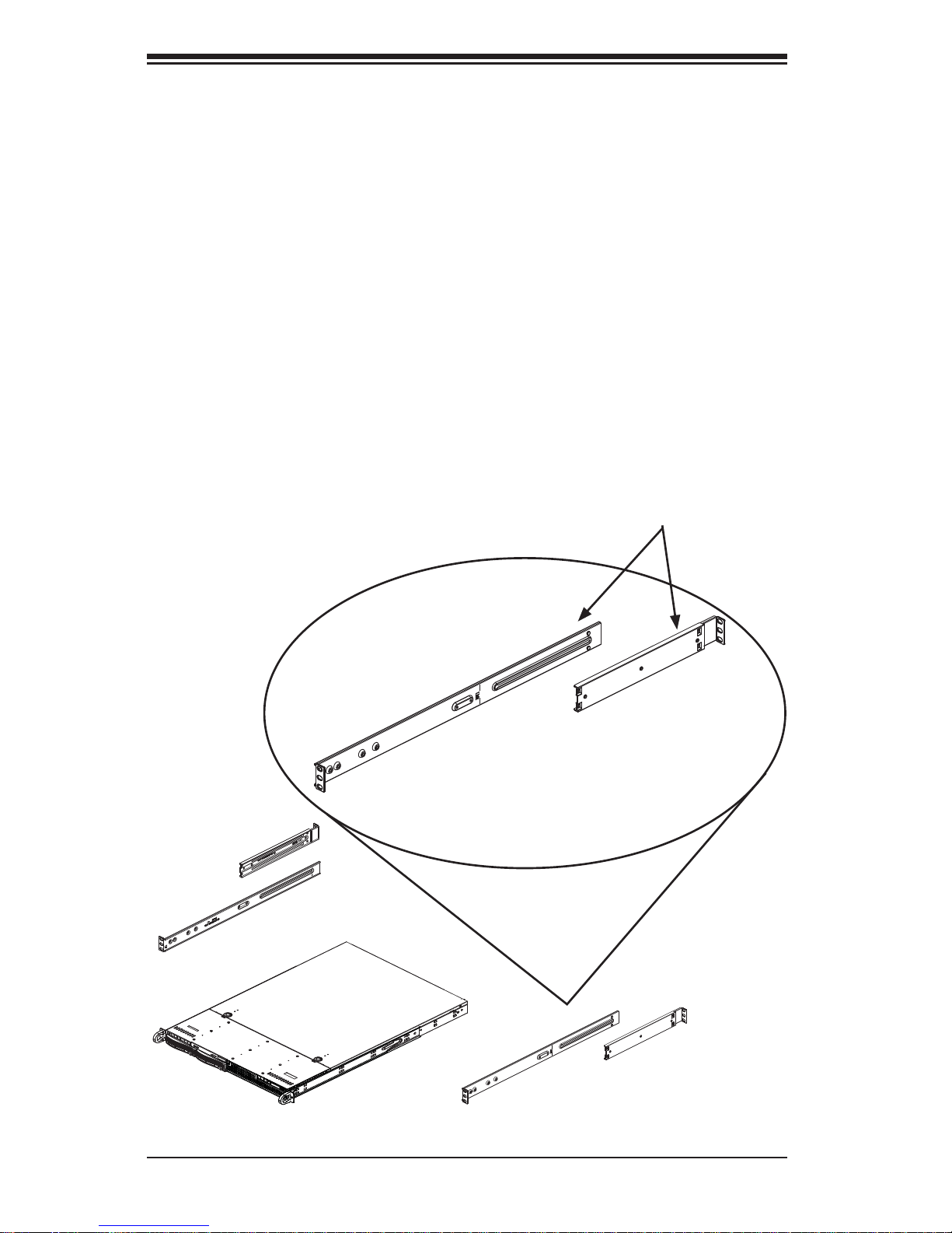
Figure 2-1. Identifying the Sections of the Rack Rails
(right side rail shown)
Outer Rails
2-5 Rack Mounting Instructions
This section provides information on installing the SC813LT-350CB chassis into
a rack unit. There are a variety of rack units on the market, which may mean the
assembly procedure will differ slightly. You should also refer to the installation
instructions that came with the rack unit you are using.
Note: This rail will fi t a rack between 26" and 33.5" deep.
Identifying the Sections of the Rack Rails
The chassis package includes two rack rail assemblies in the rack mounting kit.
Each assembly consists of two sections: an inner rail that secures directly to the
chassis, and an outer rail that secures directly to the rack itself.
Chapter 2: Server Installation
2-5
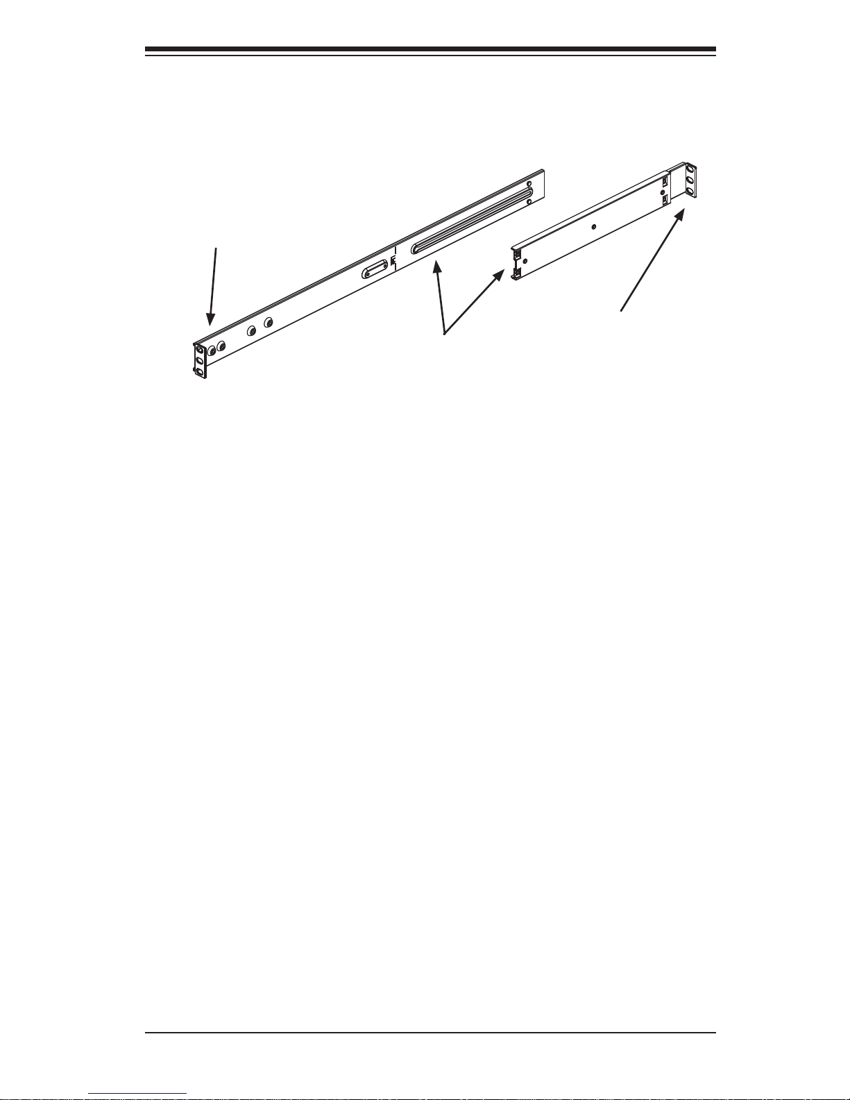
Installing the Outer Rails to the Rack
1. Attach the longer section of the outer rail to the outside of the shorter section
of the outer rail. You must align the pins with the slides. Both ends of the
outer rail must face the same direction in order to be secured to the rack.
2. Adjust both sections of the outer rail to the proper length so that the rail fi ts
snugly within the rack.
3. Secure the longer section of the outer rail to the of the rack with two M5
screws and the shorter section to the rear side of the rack with two M5
screws.
4. Repeat steps 1-4 for the remaining outer rail.
Secure to the
Front of the Rack
Secure to the
Rear of the Rack
Figure 2-2. Assembling the Outer Rails
Attach the Two Sections of the
Outer Rail Together
2-6
SUPERSERVER 6017R-TDLF User's Manual
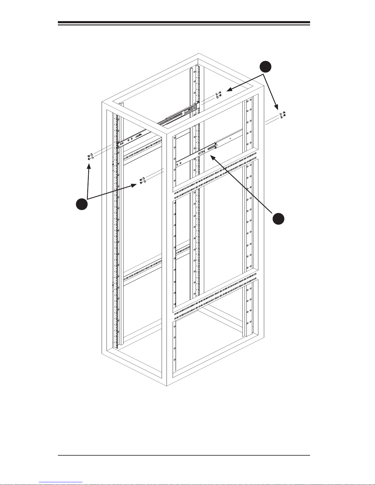
Figure 2-3. Installing the Outer Rails to the Server Rack
1
2
1
3
1
3
Chapter 2: Server Installation
2-7
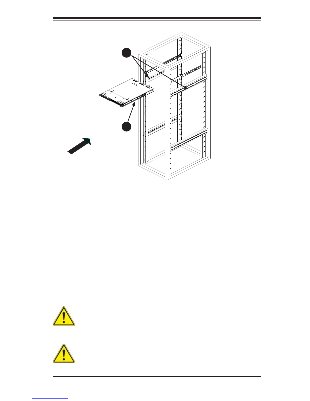
Figure 2-4. Installing the Rack Rails
Installing the Chassis into a Rack
1. Line chassis rails (A) with the front of the rack rails (B).
2. Slide the chassis rails into the rack rails, keeping the pressure even on both
sides (you may have to depress the locking tabs when inserting). When the
server has been pushed completely into the rack, you should hear the locking
tabs "click" into the locked position.
3. (Optional) Insert and tighten the thumbscrews that hold the front of the server
to the rack.
1
A
1
B
Warning: do not pick up the server with the front handles. They are de-
signed to pull the system from a rack only.
Stability hazard. The rack stabilizing mechanism must be in place, or the
rack must be bolted to the fl oor before you slide the unit out for servicing.
Failure to stabilize the rack can cause the rack to tip over.
2-8
SUPERSERVER 6017R-TDLF User's Manual
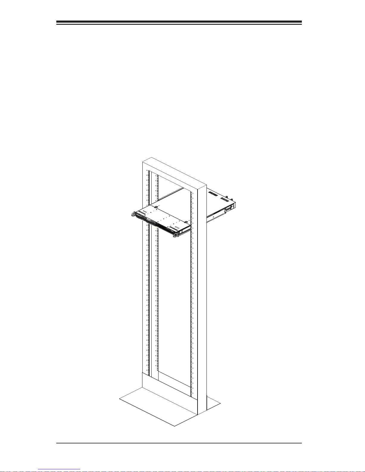
Figure 2-5. Installing the Server into a Telco Rack
Installing the Chassis into a Telco rack
To install the chassis into a Telco type rack, use two L-shaped brackets on either
side of the chassis (four total). First, determine how far follow the server will extend
out the front of the rack. Larger chassis should be positioned to balance the weight
between front and back. If a bezel is included on your server, remove it. Then attach the two front brackets to each side of the chassis, then the two rear brackets
positioned with just enough space to accommodate the width of the telco rack.
Finish by sliding the chassis into the rack and tightening the brackets to the rack.
Chapter 3: System Interface
3-1
Chapter 3
System Interface
3-1 Overview
There are several LEDs on the control panel as well as others on the hard drive
carriers to keep you constantly informed of the overall status of the system as well
as the activity and health of specifi c components. There are also two buttons on
the chassis control panel and an on/off switch on the power supply. This chapter
explains the meanings of all LED indicators and the appropriate response you may
need to take.
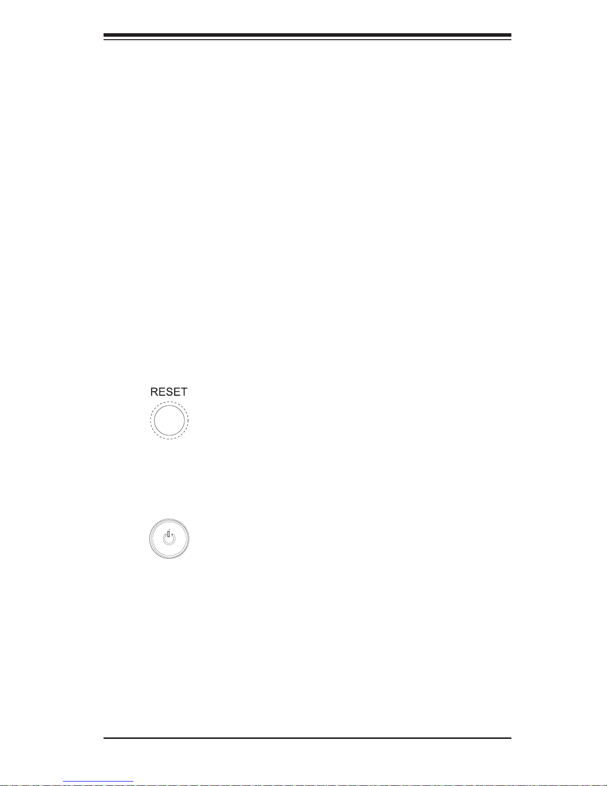
3-2 Control Panel Buttons
There are two push-buttons located on the front of the chassis: a reset button and
a power on/off button.
Reset
The reset button reboots the system.
Power
This is the main power button, which is used to apply or turn off the main system
power. T urning off system power with this button removes the main power but keeps
standby power supplied to the system.
3-2
SUPERSERVER 6017R-TDLF User's Manual
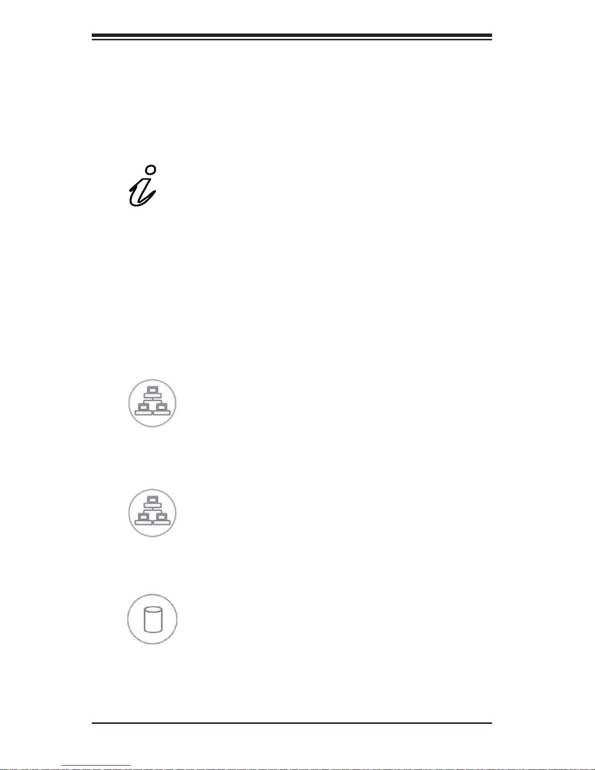
3-3 Control Panel LEDs
The control panel located on the front of the SC813LT-350CB chassis has fi ve
LEDs. These LEDs provide you with critical information related to different parts of
the system. This section explains what each LED indicates when illuminated and
any corrective action you may need to take.
1
2
Information LED
This LED will be solid blue when the UID function has been activated. When this
LED fl ashes red, it indicates a fan failure. When red continuously it indicates an
overheat condition, which may be caused by cables obstructing the airfl ow in the
system or the ambient room temperature being too warm. Check the routing of
the cables and make sure all fans are present and operating normally. You should
also check to make sure that the chassis covers are installed. Finally, verify that
the heatsinks are installed properly (see Chapter 5). This LED will remain fl ashing
or on as long as the indicated condition exists.
NIC1
Indicates network activity on LAN1 when fl ashing.
NIC2
Indicates network activity on LAN2 when fl ashing.
HDD
Channel activity for all HDDs. This light indicates hard drive activity on the 6017RTDLF when fl ashing.
Chapter 3: System Interface
3-3
Power
Indicates power is being supplied to the system's power supply units. This LED
should normally be illuminated when the system is operating.
3-4 Hard Drive Carrier LEDs
Each drive carrier has two LEDs.
• Green: When ill uminated, the green LED on the dri ve carrier i ndicates dri ve
activ ity. A connecti on to the backp lane enables t his LED to blink on an d off
when that particular drive is being accessed.
• Red: The red LED to indicate a drive failure. If one of the drives fails, you should
be notifi ed by your system management software. Please refer to Chapter 6 for
instructions on replacing failed drives.

3-4
SUPERSERVER 6017R-TDLF User's Manual
Notes
4-1
Chapter 4: Warning Statements for AC Systems
Chapter 4
Standardized Warning Statements for AC Systems
4-1 About Standardized Warning Statements
The following statements are industry standard warnings, provided to warn the user
of situations which have the potential for bodily injury. Should you have questions
or experience difficulty, contact Supermicro's Technical Support department
for assistance. Only certifi ed technicians should attempt to install or confi gure
components.
Read this appendix in its entirety before installing or confi guring components in the
Supermicro chassis.
These warnings may also be found on our web site at http://www.supermicro.com/
about/policies/safety_information.cfm.
Warning!
This warning symbol means danger. You are in a situation that could cause bodily
injury. Before you work on any equipment, be aware of the hazards involved with
electrical circuitry and be familiar with standard practices for preventing accidents.
Warning Defi nition
警告の定義
この警告サインは危険を意味します。
人身事故につながる可能性がありますので、いずれの機器でも動作させる前に、
電気回路に含まれる危険性に注意して、標準的な事故防止策に精通して下さい。
此警告符号代表危险。
您正处于可能受到严重伤害的工作环境中。在您使用设备开始工作之前,必须充分
意识到触电的危险,并熟练掌握防止事故发生的标准工作程序。请根据每项警告结
尾的声明号码找到此设备的安全性警告说明的翻译文本。
此警告符號代表危險。
您正處於可能身體可能會受損傷的工作環境中。在您使用任何設備之前,請注意觸
電的危險,並且要熟悉預防事故發生的標準工作程序。請依照每一注意事項後的號
碼找到相關的翻譯說明內容。
4-2
SUPERSERVER 6017R-TDLF User's Manual
Warnung
WICHTIGE SICHERHEITSHINWEISE
Dieses Warnsymbol bedeutet Gefahr. Sie befi nden sich in einer Situation, die zu
Verletzungen führen kann. Machen Sie sich vor der Arbeit mit Geräten mit den
Gefahren elektrischer Schaltungen und den üblichen Verfahren zur Vorbeugung
vor Unfällen vertraut. Suchen Sie mit der am Ende jeder Warnung angegebenen
Anweisungsnummer nach der jeweiligen Übersetzung in den übersetzten
Sicherheitshinweisen, die zusammen mit diesem Gerät ausgeliefert wurden.
BEWAHREN SIE DIESE HINWEISE GUT AUF.
INSTRUCCIONES IMPORTANTES DE SEGURIDAD
Este símbolo de aviso indica peligro. Existe riesgo para su integridad física. Antes
de manipular cualquier equipo, considere los riesgos de la corriente eléctrica y
familiarícese con los procedimientos estándar de prevención de accidentes. Al
fi nal de cada advertencia encontrará el número que le ayudará a encontrar el texto
traducido en el apartado de traducciones que acompaña a este dispositivo.
GUARDE ESTAS INSTRUCCIONES.
IMPORTANTES INFORMATIONS DE SÉCURITÉ
Ce symbole d'avertissement indique un danger. Vous vous trouvez dans une
situation pouvant entraîner des blessures ou des dommages corporels. Avant
de travailler sur un équipement, soyez conscient des dangers liés aux circuits
électriques et familiarisez-vous avec les procédures couramment utilisées pour
éviter les accidents. Pour prendre connaissance des traductions des avertissements
fi gurant dans les consignes de sécurité traduites qui accompagnent cet appareil,
référez-vous au numéro de l'instruction situé à la fi n de chaque avertissement.
CONSERVEZ CES INFORMATIONS.
ןונקת תורהצהאהרהז
ןה תואבה תורהצהא ינפמ שמתשמה תא ריהזהל תנמ לע ,היישעתה ינקת יפ לע תורהז הלבח
ה וא תולאש שיו הדימב .תירשפא תיזיפי ,יהשלכ היעבב תולקתרוציל שי הכימת תקלחמ םע רשק
רידגהל וא ןיקתהל םיאשר דבלב םיכמסומ םיאנכט .ורקימרפוס לש תינכט תאה .םיביכר
אורקל שי .ורקימרפוס יזראמב םיביכרה
תרדגה וא תנקתה ינפל ואולמב חפסנה תא

4-3
Warning Statements for AC Systems
안전을 위한 주의사항
경고!
이 경고 기호는 위험이 있음을 알려 줍니다. 작업자의 신체에 부상을 야기 할 수
있는 상태에 있게 됩니다. 모든 장비에 대한 작업을 수행하기 전에 전기회로와
관련된 위험요소들을 확인하시고 사전에 사고를 방지할 수 있도록 표준
작업절차를 준수해 주시기 바랍니다.
해당 번역문을 찾기 위해 각 경고의 마지막 부분에 제공된 경고문 번호를
참조하십시오
BELANGRIJKE VEILIGHEIDSINSTRUCTIES
Dit waarschuwings symbool betekent gevaar. U verkeert in een situatie die
lichamelijk letsel kan veroorzaken. Voordat u aan enige apparatuur gaat werken,
dient u zich bewust te zijn van de bij een elektrische installatie betrokken risico's
en dient u op de hoogte te zijn van de standaard procedures om ongelukken te
voorkomen. Gebruik de nummers aan het eind van elke waarschuwing om deze te
herleiden naar de desbetreffende locatie.
BEWAAR DEZE INSTRUCTIES
. ﻲﻓ ﻚﻧﺍ ﻥﺃ ﻦﻜﻤﻳ ﺔﻟﺎﺣ ﻲﻓ ﺐﺒﺴﺘﺗ ﺔﺑﺎﺻﺍ ﺔﻳﺪﺴﺟ ﺰﻣﺮﻟﺍ ﺍﺬﻫ ﻲﻨﻌﻳ ﺮﻄﺧ !ﺮﻳﺬﺤﺗ
ﻥﺃ ﻞﺒﻗ ﻱﺃ ﻰﻠﻋ ﻞﻤﻌﺗ ﺕﺍﺪﻌﻣ،ﻛﻢﻠﻋ ﻰﻠﻋ ﻦ ﻦﻋ ﺔﻤﺟﺎﻨﻟﺍ ﺮﻁﺎﺨﻤﻟﺎﺑ ﺮﺋﺍﻭﺪﻟﺍ
ﺔﻴﺋﺎﺑﺮﻬﻜﻟﺍ
ﻛﻭﺔﻳﺍﺭﺩ ﻰﻠﻋ ﻦ ﺭﺎﻤﻤﻟﺎﺑﺕﺎﺳ ﺔﻴﺋﺎﻗﻮﻟﺍ ﻟ ﻊﻨﻤﻉﻮﻗﻭ ﻱﺃﺙﺩﺍﻮﺣ
ﻢﻗﺭ ﻡﺪﺨﺘﺳﺍ ﻥﺎﻴﺒﻟﺍ ﺹﻮﺼﻨﻤﻟﺍ ﺔﻳﺎﻬﻧ ﻲﻓ ﺮﻳﺬﺤﺗ ﻞﻛ ﺭﻮﺜﻌﻠﻟ ﺎﻬﺘﻤﺟﺮﺗ
4-4
SUPERSERVER 6017R-TDLF User's Manual
Installation Instructions
Warning!
Read the installation instructions before connecting the system to the power source.
Warnung
Vor dem Anschließen des Systems an die Stromquelle die Installationsanweisungen
lesen.
¡Advertencia!
Lea las instrucciones de instalación antes de conectar el sistema a la red de
alimentación.
Attention
Avant de brancher le système sur la source d'alimentation, consulter les directives
d'installation.
設置手順書
システムを電源に接続する前に、設置手順書をお読み下さい。
ﻟﺍ ﺕﺍﺩﺎﺷﺭﺇ ﺮﻗﺍﺐﻴﻛﺮﺘ ﻞﻴﺻﻮﺗ ﻞﺒﻗ ﻰﻟﺇ ﻡﺎﻈﻨﻟﺍ ﺔﻗﺎﻄﻠﻟ ﺭﺪﺼﻣ
אורקל שי רוקמל תכרעמה רוביח ינפל הנקתה תוארוה תאחתמ.
시스템을 전원에 연결하기 전에 설치 안내를 읽어주십시오.
Waarschuwing
Raadpleeg de installatie-instructies voordat u het systeem op de voedingsbron
aansluit.
警告
将此系统连接电源前,请先阅读安装说明。
警告
將系統與電源連接前,請先閱讀安裝說明。
 Loading...