

Supero SUPERSERVER 6016T-GTF, SUPERSERVER 6016T-GIBXF, SUPERSERVER 6016T-GIBQF User Manual
SUPER
SUPERSERVER 6016T-GTF
S
UPERSERVER 6016T-GIBXF
SUPERSERVER 6016T-GIBQF
®
USER’S MANUAL
Revision 1.0

The information in this User’s Manual has been carefully reviewed and is believed to be accurate.
The vendor assumes no responsibility for any inaccuracies that may be contained in this document,
makes no commitment to update or to keep current the information in this manual, or to notify any
person or organization of the updates. Please Note: For the most up-to-date version of this
manual, please see our web site at www.supermicro.com.
Super Micro Computer, Inc. ("Supermicro") reserves the right to make changes to the product
described in this manual at any time and without notice. This product, including software, if any,
and documentation may not, in whole or in part, be copied, photocopied, reproduced, translated or
reduced to any medium or machine without prior written consent.
IN NO EVENT WILL SUPERMICRO BE LIABLE FOR DIRECT, INDIRECT , SPECIAL, INCIDENTAL,
SPECULATIVE OR CONSEQUENTIAL DAMAGES ARISING FROM THE USE OR INABILITY TO
USE THIS PRODUCT OR DOCUMENTATION, EVEN IF ADVISED OF THE POSSIBILITY OF
SUCH DAMAGES. IN PARTICULAR, SUPERMICRO SHALL NOT HAVE LIABILITY FOR ANY
HARDWARE, SOFTW ARE, OR DA TA STORED OR USED WITH THE PRODUCT, INCLUDING THE
COSTS OF REPAIRING, REPLACING, INTEGRATING, INSTALLING OR RECOVERING SUCH
HARDWARE, SOFTWARE, OR DATA.
Any disputes arising between manufacturer and customer shall be governed by the laws of Santa
Clara County in the State of California, USA. The State of California, County of Santa Clara shall
be the exclusive venue for the resolution of any such disputes. Super Micro's total liability for
all claims will not exceed the price paid for the hardware product.
FCC Statement: This equipment has been tested and found to comply with the limits for a Class
A digital device pursuant to Part 15 of the FCC Rules. These limits are designed to provide
reasonable protection against harmful interference when the equipment is operated in a commercial
environment. This equipment generates, uses, and can radiate radio frequency energy and, if not
installed and used in accordance with the manufacturer’s instruction manual, may cause harmful
interference with radio communications. Operation of this equipment in a residential area is likely
to cause harmful interference, in which case you will be required to correct the interference at your
own expense.
California Best Management Practices Regulations for Perchlorate Materials: This Perchlorate
warning applies only to products containing CR (Manganese Dioxide) Lithium coin cells. “Perchlorate
Material-special handling may apply. See www.dtsc.ca.gov/hazardouswaste/perchlorate”
WARNING: Handling of lead solder materials used in this
product may expose you to lead, a chemical known to
the State of California to cause birth defects and other
reproductive harm.
Manual Revision 1.0
Release Date: October 7, 2009
Unless you request and receive written permission from Super Micro Computer, Inc., you may not
copy any part of this document.
Information in this document is subject to change without notice. Other products and companies
referred to herein are trademarks or registered trademarks of their respective companies or mark
holders.
Copyright © 2009 by Super Micro Computer, Inc.
All rights reserved.
Printed in the United States of America

Preface
About This Manual
This manual is written for professional system integrators and PC technicians. It
provides information for the installation and use of the SuperServer 6016T-GTF/
GIBXF/GIBQF. Installation and maintenance should be performed by experienced
technicians only.
The SuperServer SuperServer 6016T-GTF/GIBXF/GIBQF is a 1U rackmount server
based on the SC818GTQ-1400B server chassis and the Super X8DTT-F/X8DTTIBXF/X8DTT-IBQF serverboards.
Manual Organization
Preface
Chapter 1: Introduction
The fi rst chapter provides a checklist of the main components included with the
server system and describes the main features of the Super X8DTT-F/X8DTT-IBXF/
X8DTT-IBQF serverboard and the SC818GTQ-1400B chassis.
Chapter 2: Server Installation
This chapter describes the steps necessary to install the SuperServer 6016T-GTF/
GIBXF/GIBQF into a rack and check out the server confi guration prior to power-
ing up the system. If your server was ordered without the processor and memory
components, this chapter will refer you to the appropriate sections of the manual
for their installation.
Chapter 3: System Interface
Refer to this chapter for details on the system interface, which includes the functions
and information provided by the control panel on the chassis as well as other LEDs
located throughout the system.
iii

SUPERSERVER 6016T-GTF/GIBXF/GIBQF User's Manual
Chapter 4: System Safety
You should thoroughly familiarize yourself with this chapter for a general overview
of safety precautions that should be followed when installing and servicing the
SuperServer 6016T-GTF/GIBXF/GIBQF.
Chapter 5: Advanced Serverboard Setup
Chapter 5 provides detailed information on the X8DTT-F/X8DTT-IBXF/X8DTT-IBQF
serverboard, including the locations and functions of connectors, headers and jumpers. Refer to this chapter when adding or removing processors or main memory
and when reconfi guring the serverboard.
Chapter 6: Advanced Chassis Setup
Refer to Chapter 6 for detailed information on the SC818GTQ-1400B 1U rackmount
server chassis. You should follow the procedures given in this chapter when installing, removing or reconfi guring SAT A or peripheral drives and when replacing system
power supply units and cooling fans.
Chapter 7: BIOS
The BIOS chapter includes an introduction to BIOS and provides detailed information on running the CMOS Setup Utility.
Appendix A: BIOS Error Beep Codes
Appendix B: Installing Windows
Appendix C: System Specifi cations
iv

Notes
Preface
v

SUPERSERVER 6016T-GTF/GIBXF/GIBQF User's Manual
Table of Contents
Chapter 1 Introduction
1-1 Overview .........................................................................................................1-1
1-2 Serverboard Features .....................................................................................1-2
Processors ......................................................................................................1-2
Memory ...........................................................................................................1-2
Serial ATA ........................................................................................................ 1-2
PCI Expansion Slots ....................................................................................... 1-2
Ethernet Ports ................................................................................................. 1-2
Onboard Controllers/Ports .............................................................................. 1-3
Graphics Controller ......................................................................................... 1-3
Other Features ................................................................................................1-3
Infi niBand ........................................................................................................ 1-3
1-3 Server Chassis Features ................................................................................ 1-5
System Power .................................................................................................1-5
SATA Subsystem .............................................................................................1-5
Front Control Panel ......................................................................................... 1-5
Cooling System ...............................................................................................1-5
1-4 Contacting Supermicro .................................................................................... 1-6
Chapter 2 Server Installation
2-1 Overview .........................................................................................................2-1
2-2 Unpacking the System ....................................................................................2-1
2-3 Preparing for Setup ......................................................................................... 2-1
Choosing a Setup Location .............................................................................2-1
Rack Precautions ............................................................................................2-2
Server Precautions ..........................................................................................2-2
Rack Mounting Considerations .......................................................................2-3
Ambient Operating Temperature ................................................................2-3
Reduced Airfl ow ......................................................................................... 2-3
Mechanical Loading ...................................................................................2-3
Circuit Overloading ..................................................................................... 2-3
Reliable Ground .........................................................................................2-3
2-4 Installing the System into a Rack ................................................................... 2-4
Identifying the Sections of the Rack Rails ...................................................... 2-4
Installing the Inner Rail Extensions ................................................................ 2-5
Assembling the Outer Rails ............................................................................ 2-6
Installing the Outer Rails onto the Rack ......................................................... 2-7
vi

Table of Contents
Installing the Server into a Telco Rack ...........................................................2-9
2-5 Checking the Serverboard Setup ..................................................................2-10
2-6 Checking the Drive Bay Setup .......................................................................2-11
Chapter 3 System Interface
3-1 Overview .........................................................................................................3-1
3-2 Control Panel Buttons .....................................................................................3-1
Reset ...............................................................................................................3-1
Power ..............................................................................................................3-1
3-3 Control Panel LEDs ........................................................................................3-2
Universal Information LED ..............................................................................3-2
NIC2 ................................................................................................................3-2
NIC1 ................................................................................................................3-3
HDD ................................................................................................................. 3-3
Power ..............................................................................................................3-3
3-4 SATA Drive Carrier LEDs ................................................................................ 3-3
Chapter 4 System Safety
4-1 Electrical Safety Precautions .......................................................................... 4-1
4-2 General Safety Precautions ............................................................................4-2
4-3 ESD Precautions .............................................................................................4-3
4-4 Operating Precautions .................................................................................... 4-4
Chapter 5 Advanced Serverboard Setup
5-1 Handling the Serverboard ...............................................................................5-1
Precautions .....................................................................................................5-1
5-2 I/O Ports .......................................................................................................... 5-2
Unpacking .......................................................................................................5-2
5-3 Processor and Heatsink Installation................................................................5-3
Installing LGA1366 Processors .......................................................................5-3
Installing a CPU Heatsink ...............................................................................5-5
Removing the Heatsink ................................................................................... 5-6
5-4 Installing Memory ............................................................................................ 5-7
5-5 Adding PCI Cards ........................................................................................... 5-9
5-6 Serverboard Details ...................................................................................... 5-10
X8DTT-F/ X8DT T-IBXF/X8DTT-IBQF Quick Reference .................................5-11
5-7 Connector Defi nitions .................................................................................... 5-12
5-8 Jumper Settings ............................................................................................5-16
5-9 Onboard Indicators ........................................................................................ 5-18
5-10 Installing Additional Drivers ...........................................................................5-19
5-11 Confi guring Supero Doctor III ....................................................................... 5-20
vii

SUPERSERVER 6016T-GTF/GIBXF/GIBQF User's Manual
Chapter 6 Advanced Chassis Setup
6-1 Static-Sensitive Devices .................................................................................. 6-1
Precautions .....................................................................................................6-1
6-2 Control Panel ..................................................................................................6-2
6-3 System Cooling ............................................................................................... 6-2
System Fan Failure ......................................................................................... 6-3
6-4 Drive Bay Installation/Removal .......................................................................6-4
Accessing the Drive Bays ...............................................................................6-4
Peripheral Drive Installation ............................................................................6-7
6-5 Installing the Air Shroud ..................................................................................6-8
Checking the Air Flow ..................................................................................... 6-8
6-6 Power Supply .................................................................................................. 6-9
Power Supply Failure ...................................................................................... 6-9
Chapter 7 BIOS
7-1 Introduction ...................................................................................................... 7-1
Starting BIOS Setup Utility ..............................................................................7-1
How To Change the Confi guration Data .........................................................7-1
Starting the Setup Utility ................................................................................. 7-2
7-2 Main Setup ...................................................................................................... 7-2
7-3 Advanced Setup Confi gurations...................................................................... 7-4
7-4 Security Settings ...........................................................................................7-24
7-5 Boot Confi guration ........................................................................................ 7-25
7-6 Exit Options ...................................................................................................7-26
Appendix A BIOS Error Beep Codes
Appendix B Installing Windows
Appendix C System Specifi cations
viii

Chapter 1: Introduction
Chapter 1
Introduction
1-1 Overview
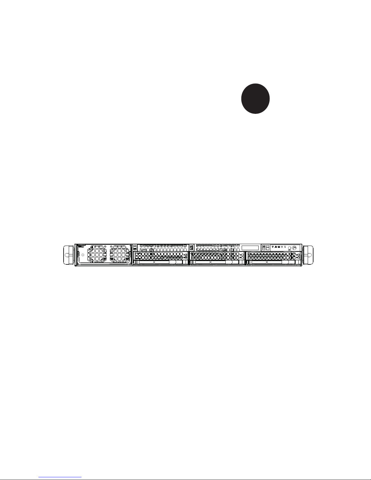
The SuperServer 6016T-GTF/GIBXF/GIBQF is a 1U server comprised of the
SC818GTQ-1400B chassis and one X8DTT-F/X8DTT-IBXF/X8DTT-IBQF serverboards. Please refer to our web site for information on operating systems that have
been certifi ed for use with the server (www.supermicro.com).
In addition to the serverboard and chassis, various hardware components may have
been included with the system, as listed below.
Two passive CPU heatsinks (SNK-P0037P)
•
Four 8-cm cooling fans (FAN-0111L4)•
One air shrouds (MCP-310-81803-0B)•
SATA Accessories: •
Three hard drive carriers (MCP-220-00001-01)
One internal HDD backplane (BPN-SAS-818TQ)
One SGPIO cable (CBL-0157L)
Three SATA cable sets (CBL-0178L)
One PCI Express x16 riser card (RSC-R1UT-E16)
•
Rackmount kit (MCP-290-00062-0N)•
One CD containing drivers and utilities•
SuperServer 6016T-GTF/GIBXF/GIBQF User's Manual•
1-1

SUPERSERVER 6016T-GTF/GIBXF/GIBQF User's Manual
1-2 Serverboard Features
At the heart of the SuperServer 6016T-GTF/GIBXF/GIBQF is one X8DTT-F/X8DTTIBXF/X8DTT-IBQF dual processor serverboards, which is based on Intel's 5520
(North Bridge) + ICH10R (South Bridge) chipset.
Below are the main features of the serverboards.
Processors
The X8DTT-F/X8DTT-IBXF/X8DTT-IBQF supports two Intel® 5500 Series processors in LGA1366 sockets. Please refer to our web site for a complete listing of
supported processors (www.supermicro.com).
Memory
The X8DTT-F/X8DTT-IBXF/X8DTT-IBQF has twelve DIMM sockets that can support up to 48 GB of registered ECC DDR3-1333/1066/800 SDRAM (192 GB for
the system). See Chapter 5 Section 6 for more details on installing memory into
the system.
Serial ATA
The Sout h Br idg e (ICH10R) of the c hips et inc lude s a Ser ial ATA cont rol ler fo r six
Gb/s SATA drives . The hot-swappable SATA drives are connected to a backplane
that provides power, bus termination and confi guration settings. RA I D 0, 1, 10 and
5 are suppo r ted. Refe r to the su ppo r t area o f our web si te for p roc edur es on s etting up RAID on your system.
PCI Expansion Slots
The X8DTT-F/X8DTT -IBXF/X8DTT -IBQF board has one PCI Express 2.0 x16 slot. In
the 6016T-GTF/IBXF/IBQF server confi guration, riser cards have been pre-installed
to support low-profi le add-on cards.
Ethernet Ports
An Intel® network controller is integrated into each of the serverboards to support
two Gigabit LAN ports (100/1000Base-T/1000BaseTX, RJ45 output).
1-2

Chapter 1: Introduction
Onboard Controllers/Ports
Onboard I/O backpanel ports on each serverboard include one COM port, a VGA
port, two USB ports, a dedicated IPMI LAN port and two Gigabit LAN (NIC) ports.
An Infi niBand port is also included on the X8DTT-IBXF/X8DTT-IBQF serverboards
(the 6016T-GIBXF and 6016T-GIBQF only).
Graphics Controller
The X8DTT-F/X8DTT-IBXF/X8DTT-IBQF features an integrated Matrox G200eW
graphics chip, which includes 8 MB of DDR2 memory.
Other Features
Other onboard features that promote system health include voltage monitors, autoswitching voltage regulators, chassis and CPU overheat sensors, virus protection
and BIOS rescue.
Infi niBand
Both the 6016T-GIBXF and 6016T-GIBQF include an Infi niBand port at DDR (dual
data rate) and QD R (quad dat a r ate) speed s, re s pe c t ive ly. Infi niBand is a scalable
serial communications link intended for connecting processors with high-speed
peripherals. (Infi niBand requires a QSFP connector.)
1-3

SUPERSERVER 6016T-GTF/GIBXF/GIBQF User's Manual
QSFP
#1
#1
#1
DDR3 DIMM
#2
#2
#2
AA
BB
CC
DDR3 DIMM
MT25408
Connect-X IB
PCI-E Gen2/DDR or QDR
PCI-E x16
DDR II
CPU#1
PE
PE
WBD
BMC/VGA
Port1 Port0
Ports
3,4
Ports
Intel
Ports
5,6
Ports
7,8,9,10
5
4-1
5520
ESI
DMI
ICH10R
PCI
CPU#2
CLINK
CLINK
LPC
2,1
#2
F
Kawela
RJ45 RJ45
SST25
VF016
SPI
SATA
SATA #1
SATA #2
SATA #3
SATA #4
SATA #5
SATA #6
LPCIO W83527
ACPI
KBC
#2
#2
DDR3 DIMM
DD
EE
F
#1
#1
#1
DDR3 DIMM
VGA
RTL8201N PHY
Dedicate LAN
Figure 1-1. Intel 5520 Chipset:
System Block Diagram
Note: This is a general block diagram. Please see Chapter 5 for details.
1-4

Chapter 1: Introduction
1-3 Server Chassis Features
System Power
The SC818GTQ-1400B features a Gold Level 1400W high-effi ciency power supply.
The AC power cord should be removed from the system before servicing or replacing the power supply. See Chapter 6 for details.
SATA Subsystem
The SC818GTQ-1400B chassis includes three 3.5" drive bays, which may be used
to house ho t-swappa ble SATA drives. R AID 0, 1, 5 and 10 are su ppor ted (R AID
5 is not supp or ted with L inux OS).
Front Control Panel
The control panel provides a system monitoring and control interface. LEDs indicate
system power, HDD activity, network activity, system overheat and power supply
failure. A main power button and a system reset button are also included.
Cooling System
The SC818GTQ-1400B has an innovative cooling design that includes four 4-cm
counter-rotating PWM (Pulse Width Modulated) fans located in the middle section
of the chassis. The power supply module also includes a cooling fan. All chassis
and power supply fans operate continuously. An air shroud channels the airfl ow
from the system fans to effi ciently cool the processors and memory. See note on
the following page regarding fan control.
1-5

SUPERSERVER 6016T-GTF/GIBXF/GIBQF User's Manual
1-4 Contacting Supermicro
Headquarters
Address: Super Micro Computer, Inc.
980 Rock Ave.
San Jose, CA 95131 U.S.A.
Tel: +1 (408) 503-8000
Fax: +1 (408) 503-8008
Email: marketing@supermicro.com (General Information)
support@supermicro.com (Technical Support)
Web Site: www.supermicro.com
Europe
Address: Super Micro Computer B.V.
Het Sterrenbeeld 28, 5215 ML
's-Hertogenbosch, The Netherlands
Tel: +31 (0) 73-6400390
Fax: +31 (0) 73-6416525
Email: sales@supermicro.nl (General Information)
support@supermicro.nl (Technical Support)
rma@supermicro.nl (Customer Support)
Asia-Pacifi c
Address: Super Micro Computer, Inc.
4F, No. 232-1, Liancheng Rd.
Chung-Ho 235, Taipei County
Taiwan, R.O.C.
Tel: +886-(2) 8226-3990
Fax: +886-(2) 8226-3991
Web Site: www.supermicro.com.tw
Technical Support:
Email: support@supermicro.com.tw
Tel: 886-2-8228-1366, ext.132 or 139
1-6
Chapter 2: Server Installation
Chapter 2
Server Installation
2-1 Overview
This chapter provides a quick setup checklist to get your SuperServer up and
running. Following these steps in the order given should enable you to have the
system operational within a minimum amount of time. This quick setup assumes
that your system has come to you with the processors and memory preinstalled. If
your system is not already fully integrated with a serverboard, processors, system
memory etc., please turn to the chapter or section noted in each step for details on
installing specifi c components.
2-2 Unpacking the System
You should inspect the box the system was shipped in and note if it was damaged
in any way. If the server itself shows damage you should fi le a damage claim with
the carrier who delivered it.
Decide on a suitable location for the rack unit that will hold the server. It should
be situated in a clean, dust-free area that is well ventilated. Avoid areas where
heat, electrical noise and electromagnetic fi elds are generated. You will also need
it placed near a grounded power outlet. Read the Rack and Server Precautions in
the next section.
2-3 Preparing for Setup
The box the server was shipped in should include two sets of rail assemblies, two
rail mounting brackets and the mounting screws you will need to install the system
into the rack. Follow the steps in the order given to complete the installation process
in a minimum amount of time. Please read this section in its entirety before you
begin the installation procedure outlined in the sections that follow.
Choosing a Setup Location
Leave enough clearance in front of the rack to enable you to open the front door •
completely (~25 inches) and approximately 30 inches of clearance in the back
of the rack to allow for suffi cient airfl ow and ease in servicing.This product is for
installation only in a Restricted Access Location (dedicated equipment rooms,
service closets and the like).
2-1
SUPERSERVER 6016T-GTF/GIBXF/GIBQF User's Manual
!
!
This product is not suitable for use with visual display work place devices •
acccording to §2 of the the German Ordinance for Work with Visual Display
Units.
Warnings and Precautions!
Rack Precautions
Ensure that the leveling jacks on the bottom of the rack are fully extended to •
the fl oor with the full weight of the rack resting on them.
In single rack installation, stabilizers should be attached to the rack. In multiple
•
rack installations, the racks should be coupled together.
Always make sure the rack is stable before extending a component from the
•
rack.
You should extend only one component at a time - extending two or more si-
•
multaneously may cause the rack to become unstable.
Rack-mounted equipment should not be used as a shelf or work space.
•
Server Precautions
Review the electrical and general safety precautions in Chapter 4.•
Determine the placement of each component in the rack • before you install the
rails.
Install the heaviest server components on the bottom of the rack fi rst, and then
•
work up.
Use a regulating uninterruptible power supply (UPS) to protect the server from
•
power surges, voltage spikes and to keep your system operating in case of a
power failure.
Allow the hot plug SATA drives and power supply modules to cool before touch-
•
ing them.
2-2

Chapter 2: Server Installation
Always keep the rack's front door and all panels and components on the servers •
closed when not servicing to maintain proper cooling.
Rack Mounting Considerations
Ambient Operating Temperature
If installed in a closed or multi-unit rack assembly, the ambient operating temperature of the rack environment may be greater than the ambient temperature of the
room. Therefore, consideration should be given to installing the equipment in an
environment compatible with the manufacturer’s maximum rated ambient temperature (Tmra).
Reduced Airfl ow
Equipment should be mounted into a rack so that the amount of airfl ow required
for safe operation is not compromised.
Mechanical Loading
Equipment should be mounted into a rack so that a hazardous condition does not
arise due to uneven mechanical loading.
Circuit Overloading
Consideration should be given to the connection of the equipment to the power
supply circuitry and the effect that any possible overloading of circuits might have
on overcurrent protection and power supply wiring. Appropriate consideration of
equipment nameplate ratings should be used when addressing this concern.
Reliable Ground
A reliable ground must be maintained at all times. To ensure this, the rack itself
should be grounded. Particular attention should be given to power supply connections other than the direct connections to the branch circuit (i.e. the use of power
strips, etc.).
2-3
SUPERSERVER 6016T-GTF/GIBXF/GIBQF User's Manual
2-4 Installing the System into a Rack
This section provides information on installing the SC818G chassis into a rack unit
with the rails provided. There are a variety of rack units on the market, which may
mean that the assembly procedure will differ slightly. You should also refer to the
installation instructions that came with the rack unit you are using.
Note: This rail will fi t a rack between 26" and 33.5" deep.
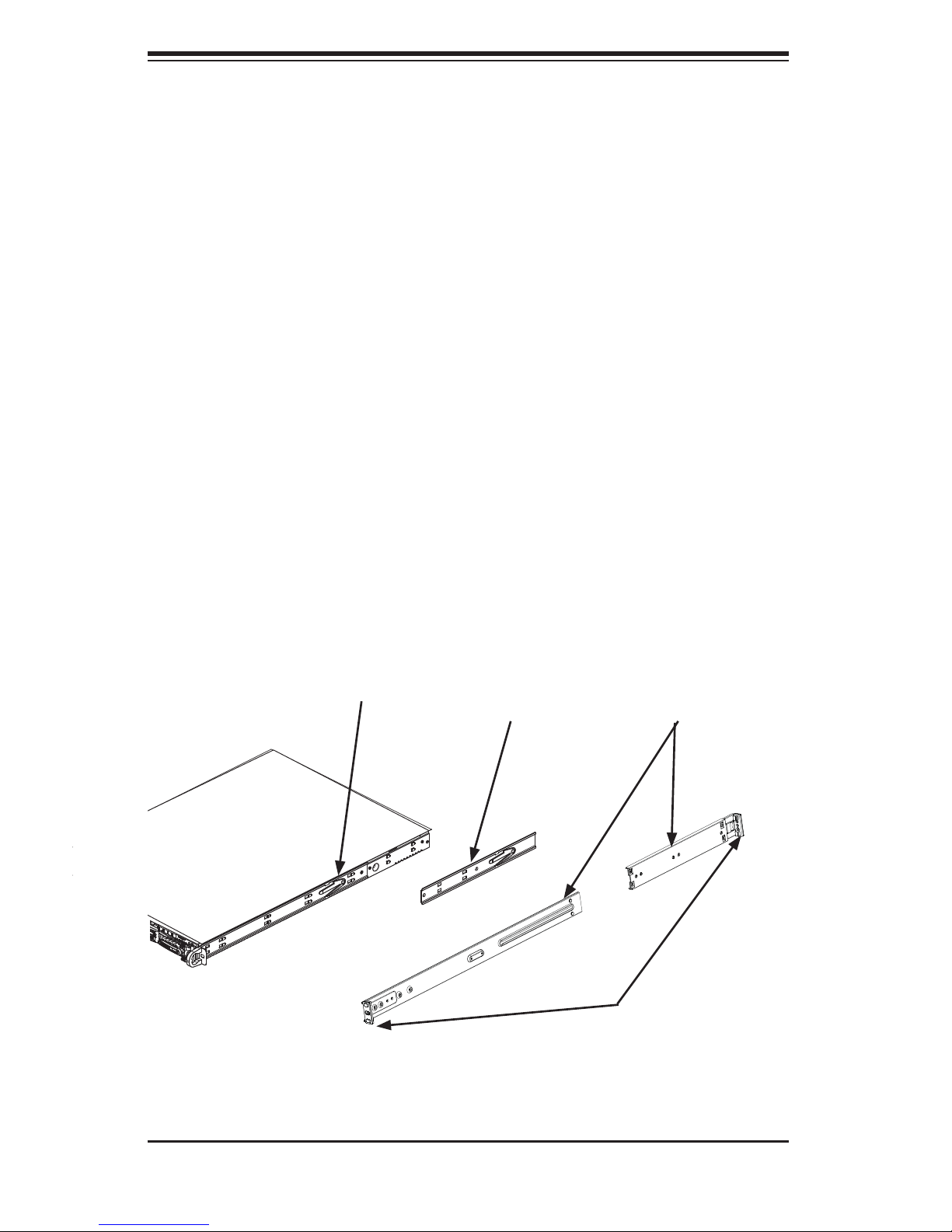
Identifying the Sections of the Rack Rails
The chassis package includes two rack rail assemblies in the rack mounting kit.
Each assembly consists of two sections: an inner fi xed chassis rail that secures
directly to the server chassis and an outer fi xed rack rail that secures directly to
the rack itself.
Figure 2-1. Identifying the Sections of the Rack Rails
Inner Rail (preattached
to the chassis)
Inner Rail
Extension:
attach to the
chassis
Outer Rails:
slide together, then
attach to the front
and rear brackets
Front and Rear
Brackets: attach to
the rack
2-4
Chapter 2: Server Installation
Installing the Inner Rail Extensions
The SC818G chassis includes a set of inner rack rails in two sections: inner rails (A)
and inner rail extensions (B). The inner rails are preattached and do not interfere
with normal use of the chassis if you decide not to install to a server rack. Attaching
the inner rail extensions to to the inner rails stabilizes the chassis within the rack.
Installing the Inner Rail Extensions
Place the inner rail extensions (B) over the preattached inner rails (A) which 1.
are attached to the side of the chassis. Align the hooks of the inner rail with
the rail extension holes. Make sure the extension faces "outward" just like the
inner rail.
Slide the extension toward the front of the chassis.2.
Secure the chassis with screws as illustrated.3.
Repeat steps 1-3 for the other inner rail extension.4.
Figure 2-2. Installing the Inner Rails
2-5
2
1
1
1
3
1
SUPERSERVER 6016T-GTF/GIBXF/GIBQF User's Manual
Assembling the Outer Rails
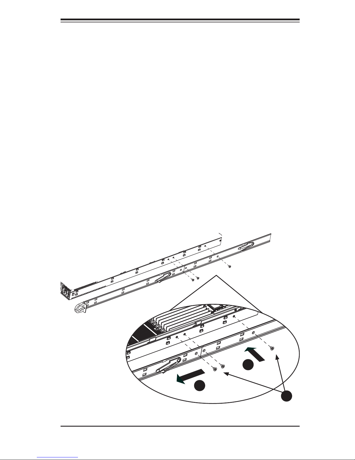
Each outer rail is in two sections that must be assembled before mounting on to
the rack.
Assembling the Outer Rails
Identify the left and right outer rails by examining the ends, which bend 1.
outward.
Slide the front section of the outer rail (A), into the rear section of the outer 2.
rail (B).
Figure 2-3. Assembling the Outer Rails
Secure to the
front of the rack
Slide outer rails
together
Assembling the sections of
A
1
the outer rail
B
1
Secure to the
rear of the rack
Outer rail assembled
2-6
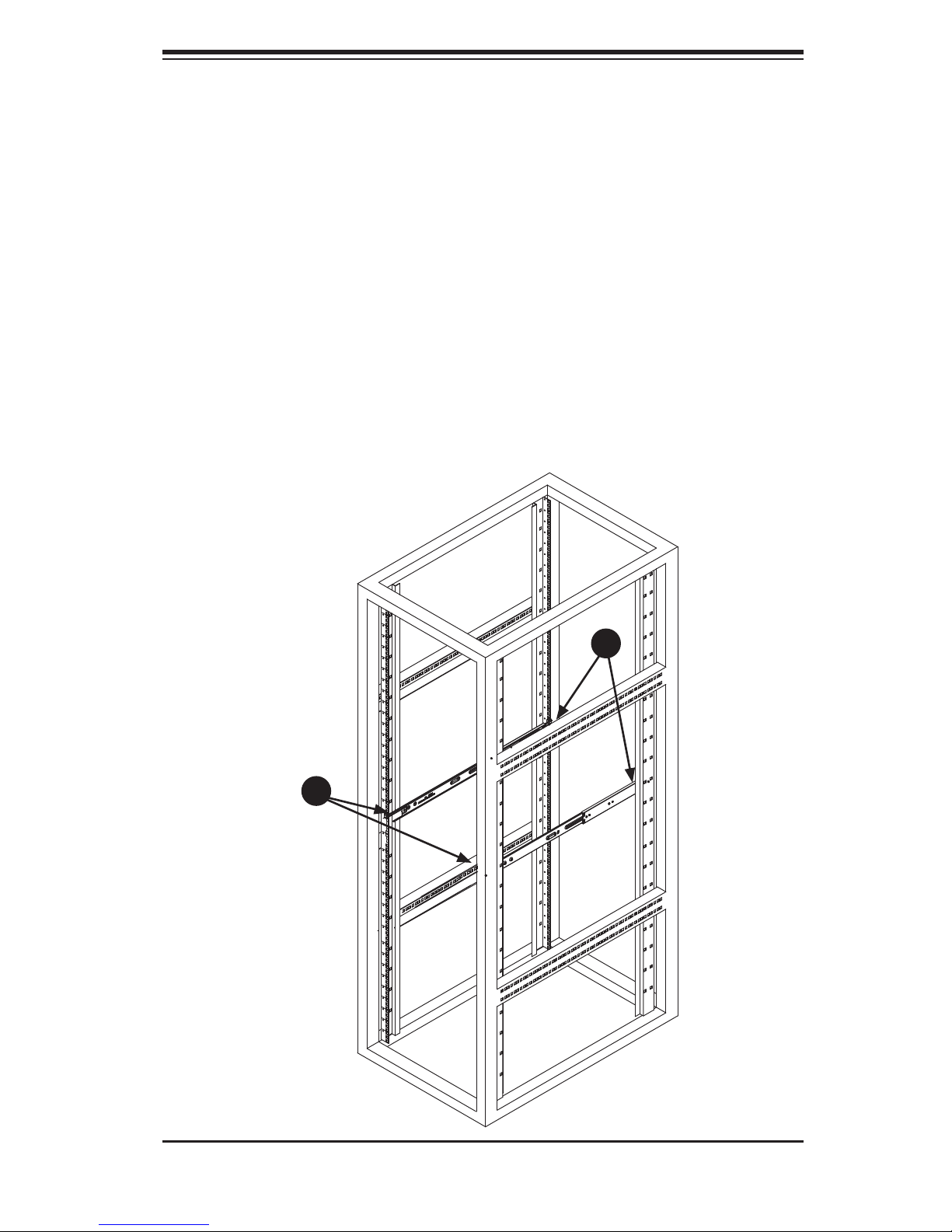
Installing the Outer Rails onto the Rack
Outer Rail Installation
Adjust the outer rails to the proper length so that the outer rail fi ts snugly 1.
within the rack.
Align the holes on the front of the outer rail, with the holes on the front of the 2.
rack (C) and secure with the screws provided.
Align the holes on the rear of the outer rail to the holes on the rack (D) and 3.
secure with the screws provided.
Repeat the procedure with the second outer rail assembly.4.
Figure 2-4. Installing the Outer Rails to the Rack
Chapter 2: Server Installation
C
1
D
1
2-7
SUPERSERVER 6016T-GTF/GIBXF/GIBQF User's Manual
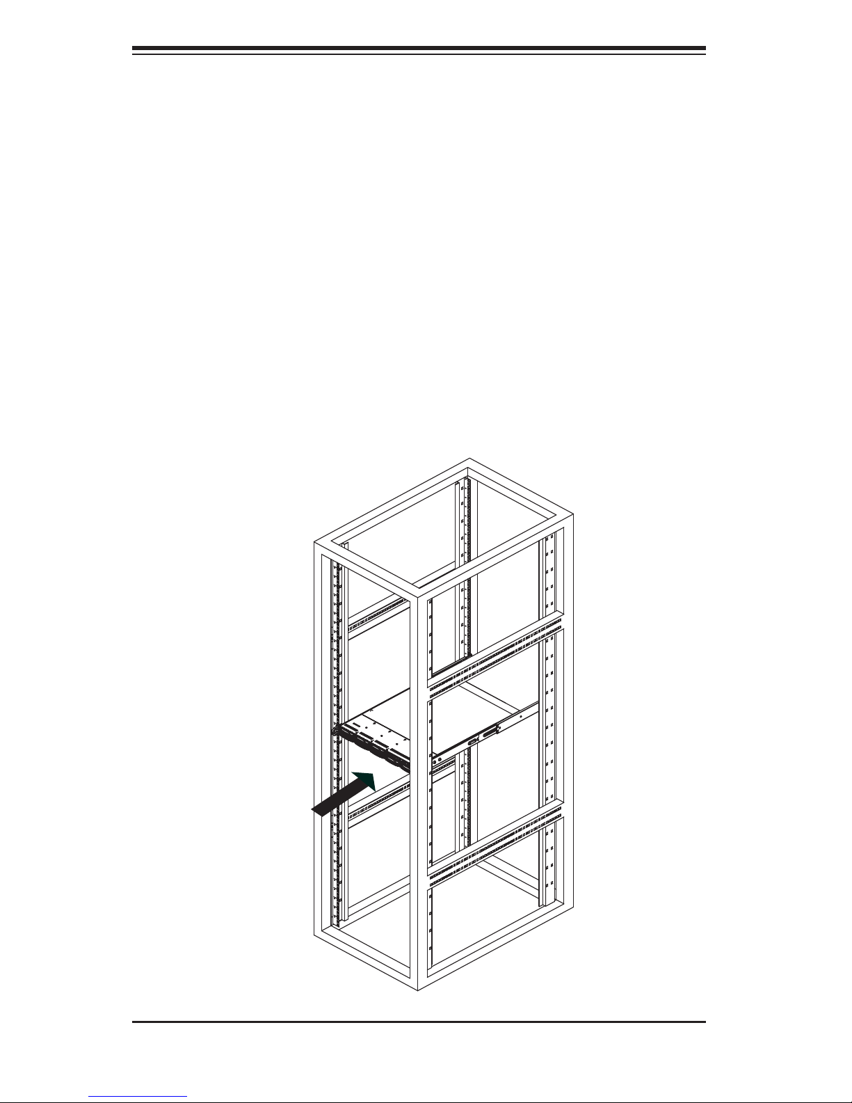
Installing the Chassis into a Rack (Figure 2-5)
Confi rm that chassis includes the inner rails and rail extensions . Also, confi rm 1.
that the outer rails are installed on the rack.
Line chassis rails with the front of the rack rails.2.
Slide the chassis rails into the rack rails, keeping the pressure even on both 3.
sides (you may have to depress the locking tabs when inserting). When the
server has been pushed completely into the rack, you should hear the locking
tabs "click".
(Optional) Insert and tightening the thumbscrews that hold the front of the 4.
server to the rack.
Figure 2-5. Installing the Server into a Rack
2-8
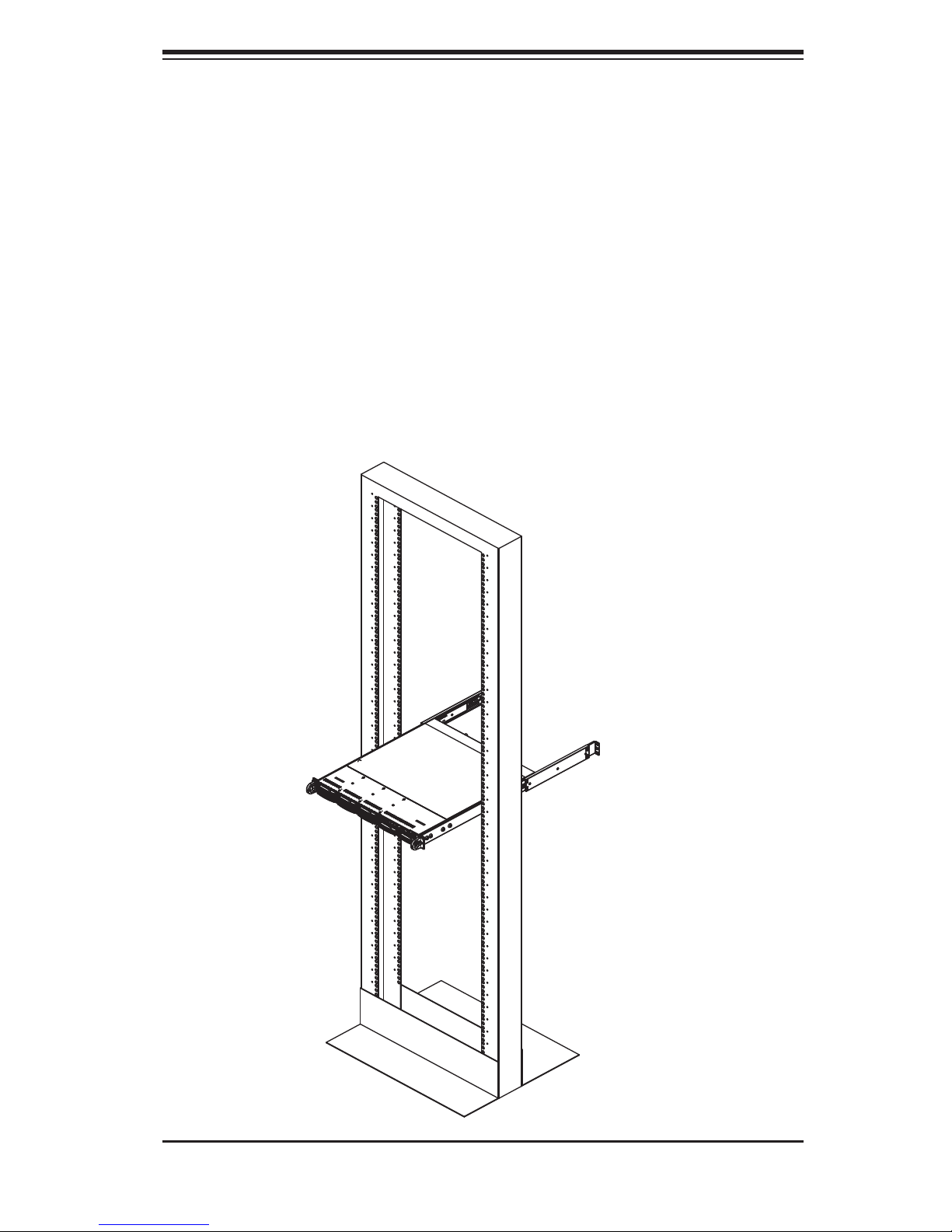
Chapter 2: Server Installation
Installing the Server into a Telco Rack
Optional brackets (p/n MCP-290-00016-0N) are needed to install the server to a
telco (open type) rack.
To install the server into a Telco type rack, use the two L-shaped brackets on either
side of the chassis (four total). First, determine how far follow the server will extend
out the front of the rack. Larger chassis should be positioned to balance the weight
between front and back. If a bezel is included on your server, remove it. Then attach the two front brackets to each side of the chassis, then the two rear brackets
positioned with just enough space to accommodate the width of the telco rack. Finish
by sliding the chassis into the rack and tightening the brackets to the rack.
Figure 2-6. Installing the Server into a Telco Rack
2-9
SUPERSERVER 6016T-GTF/GIBXF/GIBQF User's Manual
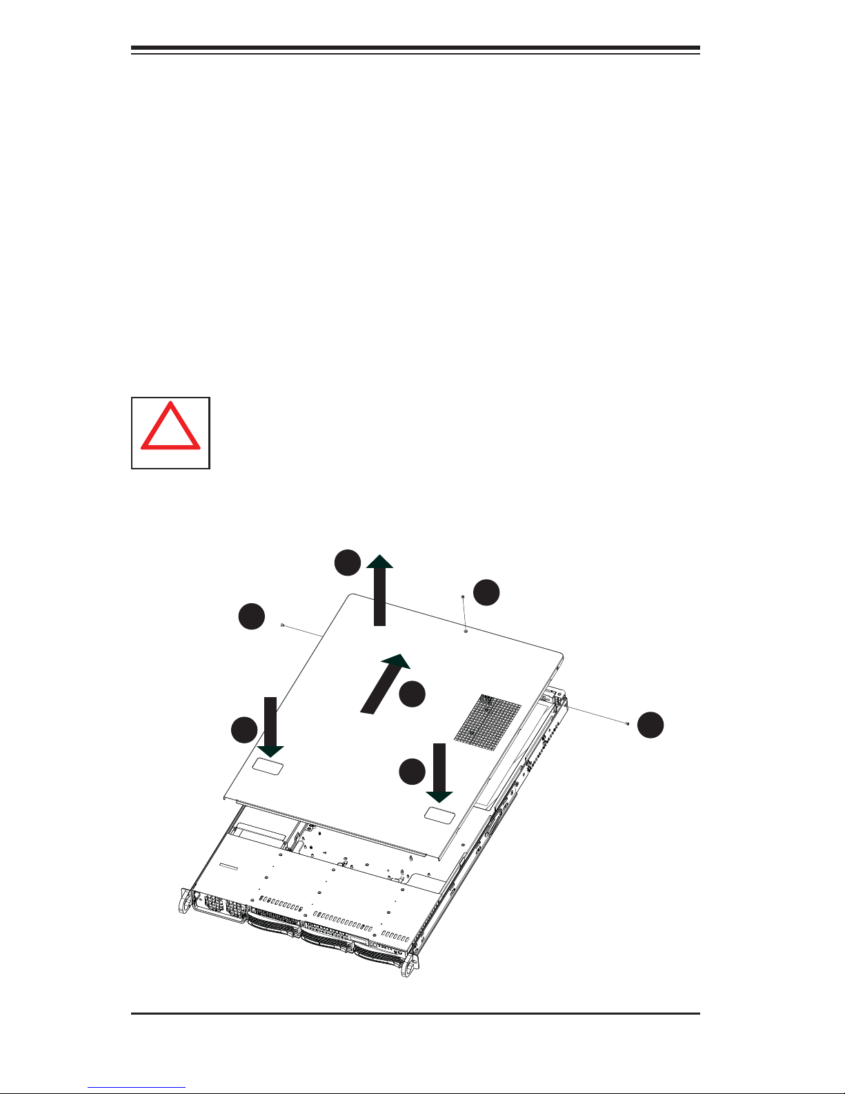
!
2-5 Checking the Serverboard Setup
After you install the server in the rack, you will need to open the unit to make sure
the serverboard is properly installed and all the connections have been made.
Removing the Chassis Cover (Figure 2-7)
Remove the three screws securing the top cover to the chassis.1.
Press both of the release tabs at the same time to release the cover 2.
Slide the cover toward the rear of the chassis.3.
Lift the cover up and off of the chassis.4.
Warning: Except for short periods of time, do NOT operate the server
without the cover in place. The chassis cover must be in place to allow
proper airfl ow and prevent overheating.
Figure 2-7: Removing the Chassis Cover
4
1
1
1
1
1
3
1
2
1
2
1
1
1
2-10

Chapter 2: Server Installation
Checking the Components
You may have processors already installed to the serverboard. Each proces-1.
sor needs its own heatsink. See Chapter 5 for instructions on processor and
heatsink installation.
Your server system may have come with system memory already installed. 2.
Make sure all DIMMs are fully seated in their slots. For details on adding
system memory, refer to Chapter 5.
If desired, you can install add-on cards to the system. See Chapter 5 for 3.
details on installing PCI add-on cards.
Make sure all power and data cables are properly connected and not block-4.
ing the chassis airfl ow. See Chapter 5 for details on cable connections. Also,
check the air seals for damage. The air seals are located under the blower
fan and beneath the frame cross section that separates the drive bay area
from the serverboard area of the chassis.
2-6 Checking the Drive Bay Setup
Next, you should check to make sure the hard drives have been properly installed
and all connections have been made.
Checking the Drives
You can add or remove hard drives from the drive carriers without having to 1.
remove the top chassis cover.
If you need to remove or install hard drives, please refer to Chapter 6.2.
Checking the Airfl ow
Airfl ow is provided by 4-cm counter-rotating fans. The system component 1.
layout was carefully designed to direct suffi cient cooling airfl ow to the compo-
nents that generate the most heat.
2-11

SUPERSERVER 6016T-GTF/GIBXF/GIBQF User's Manual
Note that all power and data cables have been routed in such a way that they 2.
do not block the airfl ow generated by the fans.
Providing Power
The last thing you must do is to provide input power to the system. Plug the 1.
power cord from the power supply unit into a high-quality power strip that offers protection from electrical noise and power surges. It is recommended that
you use an uninterruptible power supply (UPS).
Finish by depressing the power button on the chassis control panel.2.
2-12
Chapter 3: System Interface
Chapter 3
System Interface
3-1 Overview
There are several LEDs on the control panel as well as others on the drive carriers to keep you constantly informed of the overall status of the system as well
as the activity and health of specifi c components. There are also two buttons on
the chassis control panel and an on/off switch on the power supply. This chapter
explains the meanings of all LED indicators and the appropriate response you may
need to take.
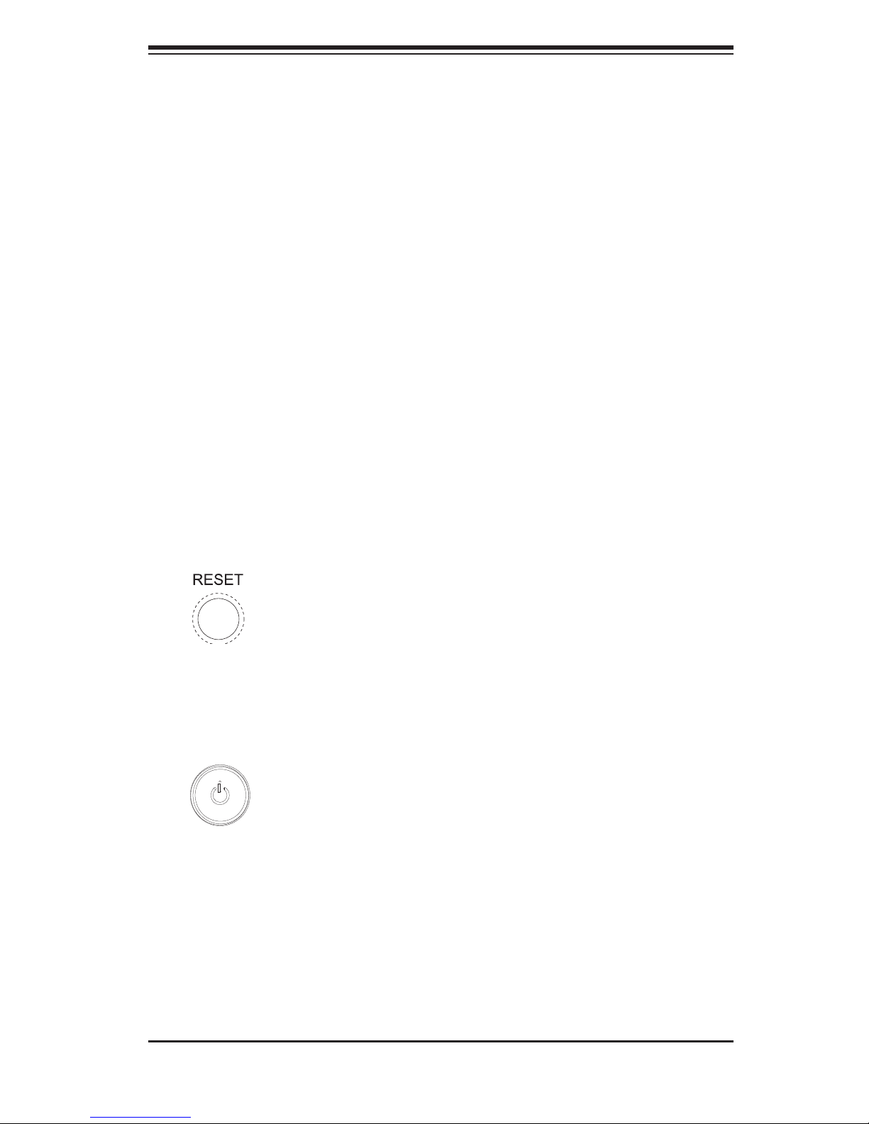
3-2 Control Panel Buttons
There are two push-buttons located on the front of the chassis: a reset button and
a power on/off button.
Reset
Use the reset button to reboot the system.
Power
The main power button is used to apply or remove power from the power supply
to the server system. Turning off system power with this button removes the main
power but keeps standby power supplied to the system.
3-1
SUPERSERVER 6016T-GTF/GIBXF/GIQXF User's Manual
3-3 Control Panel LEDs
The control panel located on the front of the SC818GTQ chassis has fi ve LEDs.
These LEDs provide you with critical information related to different parts of the
system. This section explains what each LED indicates when illuminated and any
corrective action you may need to take.
Universal Information LED
When this LED blinks red quickly, it indicates a fan failure. This LED will be blue
when used for UID (Unit Identifi er). When on continuously it indicates an overheat
condition, which may be caused by cables obstructing the airfl ow in the system or
the ambient room temperature being too warm. Check the routing of the cables and
make sure all fans are present and operating normally. You should also check to
make sure that the chassis covers are installed. Finally , verify that the heatsinks are
installed properly (see Chapter 5). This LED will remain fl ashing or on as long as the
indicated condition exists. See the table below for descriptions of the LED states.
Figure 3-1. Universal Information LED States
Universal Information LED States
State Indication
Fast Blinking Red (1x/sec) Fan Fail
Solid Red CPU Overheat
Solid Blue Local UID Button Depressed
Blinking Blue IPMI-Activated UID
Note: deactivating the UID LED must be performed in the same way it was activated.
(If the UID LED was activated via IPMI, you can only turn the LED off via IPMI and
not with the UID button.)
2
NIC2
Indicates network activity on LAN2 when fl ashing .
3-2
Chapter 3: System Interface
1
NIC1
Indicates network activity on LAN1 when fl ashing .
HDD
This light i ndic ates SATA and/or DVD - ROM dr ive activ ity w hen fl ashing.
Power
Indic ates power is bein g supplied to the sy stem's power supply u nits. This LED
should normally be illuminated when the system is operating.
3-4 SATA Drive Carrier LEDs
Green:• Each Ser i al ATA drive carr ie r ha s a gr ee n LED. Wh en i ll umi nate d, t hi s
green LED (on th e front of the SATA drive c arrier) indi cates drive ac tivity. A
conne cti on to th e SATA backpla ne enab les th is LED to bl ink on an d off w hen
that particular drive is being accessed. Please refer to Chapter 6 for instructions
on replacing failed SATA drives.
Red:
• The red LED to indicate an SATA drive failure. If one of the SATA drives
fail, you should be notifi ed by your system management software. Please refer
to Chapter 6 for instructions on replacing failed SATA drives.
3-3

SUPERSERVER 6016T-GTF/GIBXF/GIQXF User's Manual
Notes
3-4
 Loading...