

Page 1
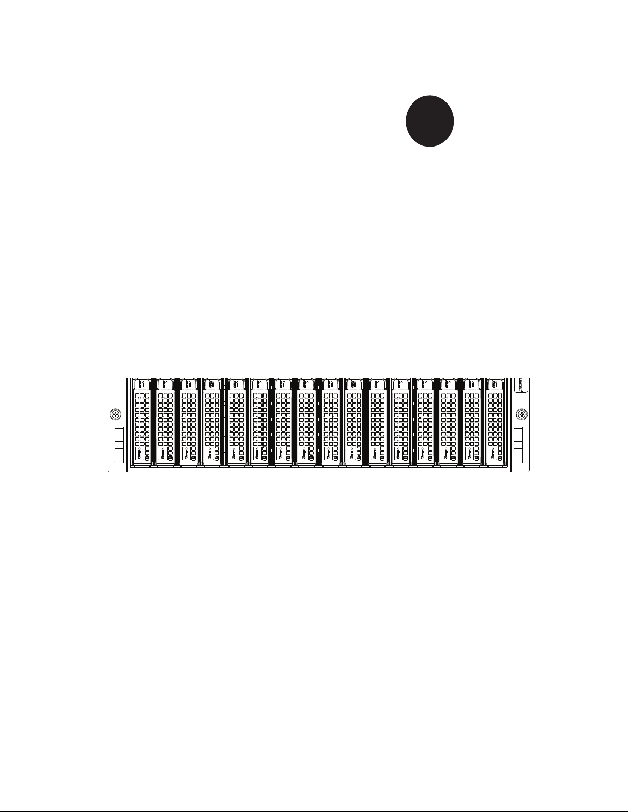
SUPER
SUPERSERVER
®
Super Microcloud
5037MC-H8TRF
TM
USER’S MANUAL
Revision 1.0
Page 2

The information in this User’s Manual has been carefully reviewed and is believed to be accurate.
The vendor assumes no responsibility for any inaccuracies that may be contained in this document,
makes no commitment to update or to keep current the information in this manual, or to notify any
person or organization of the updates. Please Note: For the most up-to-date version of this
manual, please see our web site at www.supermicro.com.
Super Micro Computer, Inc. ("Supermicro") reserves the right to make changes to the product
described in this manual at any time and without notice. This product, including software and documentation, is the property of Supermicro and/or its licensors, and is supplied only under a license.
Any use or reproduction of this product is not allowed, except as expressly permitted by the terms
of said license.
IN NO EVENT WILL SUPERMICRO BE LIABLE FOR DIRECT, INDIRECT, SPECIAL, INCIDENTAL,
SPECULATIVE OR CONSEQUENTIAL DAMAGES ARISING FROM THE USE OR INABILITY TO
USE THIS PRODUCT OR DOCUMENTATION, EVEN IF ADVISED OF THE POSSIBILITY OF
SUCH DAMAGES. IN PARTICULAR, SUPERMICRO SHALL NOT HAVE LIABILITY FOR ANY
HARDWARE, SOFTWARE, OR DATA STORED OR USED WITH THE PRODUCT, INCLUDING THE
COSTS OF REPAIRING, REPLACING, INTEGRATING, INSTALLING OR RECOVERING SUCH
HARDWARE, SOFTWARE, OR DATA.
Any disputes arising between manufacturer and customer shall be governed by the laws of Santa
Clara County in the State of California, USA. The State of California, County of Santa Clara shall
be the exclusive venue for the resolution of any such disputes. Super Micro's total liability for all
claims will not exceed the price paid for the hardware product.
FCC Statement: This equipment has been tested and found to comply with the limits for a Class A
digital device pursuant to Part 15 of the FCC Rules. These limits are designed to provide reasonable
protection against harmful interference when the equipment is operated in a commercial environment. This equipment generates, uses, and can radiate radio frequency energy and, if not installed
and used in accordance with the manufacturer’s instruction manual, may cause harmful interference
with radio communications. Operation of this equipment in a residential area is likely to cause harmful
interference, in which case you will be required to correct the interference at your own expense.
California Best Management Practices Regulations for Perchlorate Materials: This Perchlorate warning applies only to products containing CR (Manganese Dioxide) Lithium coin cells. “Perchlorate
Material-special handling may apply. See www.dtsc.ca.gov/hazardouswaste/perchlorate”
WARNING: Handling of lead solder materials used in this
product may expose you to lead, a chemical known to the
State of California to cause birth defects and other reproductive harm.
Manual Revision 1.0
Release Date: September 14, 2011
Unless you request and receive written permission from Super Micro Computer, Inc., you may not
copy any part of this document.
Information in this document is subject to change without notice. Other products and companies
referred to herein are trademarks or registered trademarks of their respective companies or mark
holders.
Copyright © 2011 by Super Micro Computer, Inc.
All rights reserved.
Printed in the United States of America
Page 3

Preface
About This Manual
This manual is written for professional system integrators and PC technicians. It
provides information for the installation and use of the SuperServer 5037MC-H8TRF.
Installation and maintenance should be performed by experienced technicians
only.
Preface
The SuperServer 5037MC-H8TRF is an 8-node, Microcloud
based on the SC938H-R1620B 3U chassis and eight X9SCD-F motherboards. The
X9SCD-F supports single Intel® Xeon® E3-1200 Series processors. Please refer
to our web site for an up-to-date list of supported processors.
TM
server system
Manual Organization
Chapter 1: Introduction
The fi rst chapter provides a checklist of the main components included with the
system and describes the main features of the Super X9SCD-F motherboard and
the SC938H-R1620B chassis.
Chapter 2: Server Installation
This chapter describes the steps necessary to install the server into a rack and
check out the server confi guration prior to powering up the system. If your server
was ordered without the processor and memory components, this chapter will refer
you to the appropriate sections of the manual for their installation.
Chapter 3: System Interface
Refer to this chapter for details on the system interface, which includes the functions
and information provided by the control panel on the chassis as well as other LEDs
located throughout the system.
iii
Page 4

SUPERSERVER 5037MC-H8TRF User's Manual
Chapter 4: System Safety
You should thoroughly familiarize yourself with this chapter for a general overview
of safety precautions that should be followed when installing and servicing the
SuperServer 5037MC-H8TRF.
Chapter 5: Advanced Motherboard Setup
Chapter 5 provides detailed information on the X9SCD-F motherboard, including the
locations and functions of connectors, headers and jumpers. Refer to this chapter
when adding or removing processors or main memory and when reconfi guring the
motherboard.
Chapter 6: Advanced Chassis Setup
Refer to Chapter 6 for detailed information on the SC938H-R1620B 3U server
chassis. You should follow the procedures given in this chapter when installing,
removing or reconfi guring drives and when replacing system power supply units
and cooling fans.
Chapter 7: BIOS
The BIOS chapter includes an introduction to BIOS and provides detailed informa-
tion on running the CMOS Setup Utility.
Appendix A: BIOS POST Codes
Appendix B: System Specifi cations
iv
Page 5

Notes
Preface
v
Page 6

SUPERSERVER 5037MC-H8TRF User's Manual
Table of Contents
Chapter 1 Introduction
1-1 Overview ......................................................................................................... 1-1
1-2 Motherboard Features ..................................................................................... 1-2
Processors ...................................................................................................... 1-2
Memory ........................................................................................................... 1-2
SATA .............................................................................................................. 1-2
Rear I/O Ports ................................................................................................. 1-2
Graphics .......................................................................................................... 1-2
IPMI ................................................................................................................. 1-3
Other Features ................................................................................................ 1-3
1-3 Server Chassis Features ................................................................................ 1-4
System Power ................................................................................................. 1-4
Front Control Panel ......................................................................................... 1-4
Cooling System ............................................................................................... 1-4
1-4 Contacting Supermicro .................................................................................... 1-5
Chapter 2 Server Installation
2-1 Overview ......................................................................................................... 2-1
2-2 Unpacking the System .................................................................................... 2-1
2-3 Preparing for Setup ......................................................................................... 2-1
Choosing a Setup Location ............................................................................. 2-2
Rack Precautions ............................................................................................ 2-2
Server Precautions .......................................................................................... 2-2
Rack Mounting Considerations ....................................................................... 2-3
Ambient Operating Temperature ................................................................ 2-3
Reduced Airfl ow ......................................................................................... 2-3
Mechanical Loading ................................................................................... 2-3
Circuit Overloading ..................................................................................... 2-3
Reliable Ground ......................................................................................... 2-3
2-4 Installing the System into a Rack ................................................................... 2-4
Identifying the Sections of the Rack Rails ...................................................... 2-4
Locking Tabs ................................................................................................... 2-5
Releasing the Inner Rail ................................................................................. 2-5
Installing The Inner Rails on the Chassis ....................................................... 2-6
Installing the Outer Rails on the Rack ............................................................ 2-7
Standard Chassis Installation ......................................................................... 2-8
Optional Quick Installation Method ................................................................. 2-9
vi
Page 7

Table of Contents
2-5 Checking the Motherboard Setup ................................................................. 2-10
2-6 Preparing to Power On ................................................................................. 2-12
Chapter 3 System Interface
3-1 Overview ......................................................................................................... 3-1
3-2 Control Panel Buttons ..................................................................................... 3-1
Power Button/LED ........................................................................................... 3-1
3-3 LEDs ................................................................................................................ 3-2
Power Failure LED .......................................................................................... 3-2
3-4 Hard Drive Carrier LEDs ................................................................................. 3-3
3-5 Node LEDs ...................................................................................................... 3-3
Power Button and LED ................................................................................... 3-4
UIO Button and LED ....................................................................................... 3-4
Failure LED ..................................................................................................... 3-4
Chapter 4 System Safety
4-1 Electrical Safety Precautions .......................................................................... 4-1
4-2 General Safety Precautions ............................................................................ 4-2
4-3 ESD Precautions ............................................................................................. 4-3
4-4 Operating Precautions .................................................................................... 4-4
Chapter 5 Advanced Motherboard Setup
5-1 Handling the Motherboard .............................................................................. 5-1
Precautions ..................................................................................................... 5-1
Unpacking ....................................................................................................... 5-2
5-2 Motherboard Installation .................................................................................. 5-2
5-3 Connecting Cables .......................................................................................... 5-2
5-4 I/O Ports .......................................................................................................... 5-2
5-5 Processor and Heatsink Installation................................................................ 5-3
Installing an LGA1155 Processor .................................................................. 5-3
Installing a Heatsink ........................................................................................ 5-5
5-6 Installing Memory ............................................................................................ 5-6
How to Install DDR3 DIMMs ........................................................................... 5-6
Memory Support .............................................................................................. 5-6
Installing and Removing DIMMs ..................................................................... 5-7
Guidelines for Populating Memory .................................................................. 5-8
5-7 Adding PCI Add-On Cards .............................................................................. 5-8
5-8 Motherboard Details ...................................................................................... 5-10
X9SCD-F Quick Reference ............................................................................5-11
5-9 Connector Defi nitions ................................................................................... 5-12
5-10 I/O Port Defi nitions ....................................................................................... 5-13
vii
Page 8

SUPERSERVER 5037MC-H8TRF User's Manual
5-11 Jumper Settings ............................................................................................ 5-14
5-12 Onboard Indicators ........................................................................................ 5-16
5-13 SATA Drive Connections ............................................................................... 5-17
5-14 Installing Software ......................................................................................... 5-17
Supero Doctor III ........................................................................................... 5-18
Chapter 6 Advanced Chassis Setup
6-1 Static-Sensitive Devices .................................................................................. 6-1
Precautions ..................................................................................................... 6-1
6-2 Removing the Chassis Cover ......................................................................... 6-2
6-3 Corresponding Nodes, Fans and Hard Drives ................................................ 6-3
6-4 Removing and Installing Hard Drives ............................................................. 6-4
6-5 Removing and Installing the Backplane .......................................................... 6-7
6-6 Removing and Installing Motherboard Nodes ................................................6-11
6-7 Installing the Air Shroud ................................................................................ 6-12
6-8 System Fans ................................................................................................. 6-13
6-9 Power Supply ................................................................................................ 6-14
Power Supply Replacement .......................................................................... 6-14
Chapter 7 BIOS
7-1 Introduction ...................................................................................................... 7-1
7-2 Main Setup ...................................................................................................... 7-2
7-3 Advanced Setup Confi gurations...................................................................... 7-4
7-4 Event Logs .................................................................................................... 7-15
7-5 IPMI Confi guration ........................................................................................ 7-16
7-6 Boot Settings .................................................................................................7-18
7-7 Security Settings ........................................................................................... 7-19
7-8 Exit Options ................................................................................................... 7-20
Appendix A POST Error Beep Codes
Appendix B System Specifi cations
viii
Page 9

Chapter 1: Introduction
Chapter 1
Introduction
1-1 Overview
The SuperServer 5037MC-H8TRF is an eight node, MicrocloudTM server system
comprised of two main subsystems: the SC938H-R1620B 3U chassis and eight
X9SCD-F motherboards. Please refer to our web site for information on operating
systems that have been certifi ed for use with the 5037MC-H8TRF (www.supermicro.
com).
In addition to the motherboard and chassis, various hardware components have
been included with the 5037MC-H8TRF, as listed below:
• Four chassis fans (FAN-0115L4)
• One passive heatsink, each node (SNK-P0047PS)
• One air shroud, each node (MCP-310-93801-0B)
• One riser card, each node (RSC-RR1U-E8)
• SATA Accessories
One SATA backplane (BPN-SAS-938H)
Sixteen hot-swap hard drive carriers (MCP-220-00094-0B)
• One rail kit (MCP-280-93801-0B)
• One SuperServer 5037MC-H8TRF User's Manual
1-1
Page 10

SUPERSERVER 5037MC-H8TRF User's Manual
1-2 Motherboard Features
The 5037MC-H8TRF includes a total of eight X9SCD-F single processor mother-
boards, which are based on the Intel C204 PCH chipset. Below are the main features
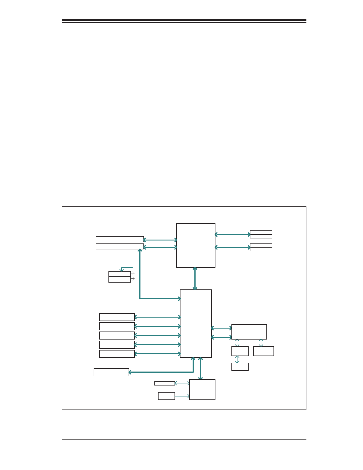
of the X9SCD-F. (See Figure 1-1 for a block diagram of the chipset).
Processors
Each X9SCD-F supports a single Intel E3-1200 Series processor in an LGA 1155
socket. Please refer to the motherboard description pages on our web site for a
complete listing of supported processors (www.supermicro.com).
Memory
The X9SCD-F has four DIMM slots that can support up to 32 GB of ECC DDR3-
1333/1066 UDIMM. This equates to a maximum of 256 GB for the system. Memory
modules of the same size and speed should be used. See Chapter 5 for details.
SATA
A SATA controller is integrated into the chipset to provide a four-port SATA subsys-
tem. The SATA drives are hot-swappable units.
Note: The operating system you use must have RAID support to enable the hot-
swap capability and RAID function of the SATA drives.
Rear I/O Ports
The rear I/O panel includes one KVM connector, an IPMI port, a power LED and
buttons for UID (Unit Identifi cation) and power.
Graphics
There is no onboard graphics controller on the X9SCD-F. A VGA port is included
on the KVM connector.
1-2
Page 11
Chapter 1: Introduction
Cougar Point
DDR3 (CHA)
Sandy Bridge
PCIe2.0_x8
VRM 12
SVID
PCIe x8 SLOT
DDR3 (CHB)
DIMM1
DIMM2(Far)
DIMM1
DIMM2(Far)
4 UDIMM
MISC VRs
1333/1066MHz
1333/1066MHz
5GT/s
x4 DMI II
5GT/s
P11-12
P29-30
LPC
RMII
VGA (KVM)
RTL8201
PHY
HERMON WPCM450
WINBOND
PCI32
RJ45
PCIe2.0_x8
PCIe x8 SLOT (Micro LP)
5GT/s
600MB/s
SATA-III
PCH
C204
2 SATA PORTS (BP)
300MB/s
SATA-II
1 SATA PORT (DOM)
3 USB PORTS
USB2.0
480Mbps
2 USB PORTS (KVM)
USB2.0
480Mbps
LPC
TPM1.2 Header
COM1(KVM)
LPC
HEALTH
INFO
LPC I/O
NCT6776F
FLASH
SPI 64Mb
SPI
PCIe2.0 x1
5GT/s
IPMI
IPMI (Intelligent Platform Management Interface) is a hardware-level interface speci-
fi cation that provides remote access, monitoring and administration for Supermicro
server platforms. IPMI allows server administrators to view a server’s hardware
status remotely, receive an alarm automatically if a failure occurs, and power cycle
a system that is non-responsive.
Other Features
Other onboard features that promote system health include onboard voltage moni-
tors, a chassis intrusion header, auto-switching voltage regulators, chassis and CPU
overheat sensors, virus protection and BIOS rescue.
Figure 1-1. Intel 7500 Chipset:
System Block Diagram
Note: This is a general block diagram. See Chapter 5 for details.
1-3
Page 12

SUPERSERVER 5037MC-H8TRF User's Manual
1-3 Server Chassis Features
The following is a general outline of the main features of the SC938H-R1620B
server chassis.
System Power
The SC938H-R1620B features a redundant (two separate power modules) 1620W
high-effi ciency power supply. This power redundancy feature allows you to replace
a failed power supply without shutting down the system.
Front Control Panel
The control panel on the 5037MC-H8TRF features a power button/LED, a power fail
LED and eight LEDs to indicate the status of each node in the system.
Cooling System
The SC938H-R1620B chassis includes four 8-cm fans located behind the back-
plane. Each fan is associated with and controlled by two nodes. Each node also
has an air shroud to channel the airfl ow from the system fans to effi ciently cool the
components that generate the most heat. See Chapter 6 for details.
1-4
Page 13

Chapter 1: Introduction
1-4 Contacting Supermicro
Headquarters
Address: Super Micro Computer, Inc.
980 Rock Ave.
San Jose, CA 95131 U.S.A.
Tel: +1 (408) 503-8000
Fax: +1 (408) 503-8008
Email: [email protected] (General Information)
[email protected] (Technical Support)
Web Site: www.supermicro.com
Europe
Address: Super Micro Computer B.V.
Het Sterrenbeeld 28, 5215 ML
's-Hertogenbosch, The Netherlands
Tel: +31 (0) 73-6400390
Fax: +31 (0) 73-6416525
Email: [email protected] (General Information)
[email protected] (Technical Support)
[email protected] (Customer Support)
Asia-Pacifi c
Address: Super Micro Computer, Inc.
4F, No. 232-1, Liancheng Rd.
Chung-Ho 235, Taipei County
Taiwan, R.O.C.
Tel: +886-(2) 8226-3990
Fax: +886-(2) 8226-3991
Web Site: www.supermicro.com.tw
Technical Support:
Email: [email protected]
Tel: 886-2-8226-5990
1-5
Page 14

SUPERSERVER 5037MC-H8TRF User's Manual
Notes
1-6
Page 15

Chapter 2: Server Installation
Chapter 2
Server Installation
2-1 Overview
This chapter provides a quick setup checklist to get your 5037MC-H8TRF up and
running. Following these steps in the order given should enable you to have the
system operational within a minimum amount of time. This quick setup assumes
that your system has come to you with the processors and memory preinstalled. If
your system is not already fully integrated with a motherboard, processors, system
memory etc., please turn to the chapter or section noted in each step for details on
installing specifi c components.
2-2 Unpacking the System
You should inspect the box the 5037MC-H8TRF was shipped in and note if it was
damaged in any way. If the server itself shows damage you should fi le a damage
claim with the carrier who delivered it.
Decide on a suitable location for the rack unit that will hold the 5037MC-H8TRF.
It should be situated in a clean, dust-free area that is well ventilated. Avoid areas
where heat, electrical noise and electromagnetic fi elds are generated. You will also
need it placed near a grounded power outlet. Be sure to read the Rack and Server
Precautions in the next section.
2-3 Preparing for Setup
The 5037MC-H8TRF may have come with hardware to mount the system into
a server rack. If mounting to a rack with the rail kit, follow the steps in the order
given to complete the installation process in a minimum amount of time. Please
read this section in its entirety before you begin the installation procedure outlined
in the sections that follow.
2-1
Page 16
SUPERSERVER 5037MC-H8TRF User's Manual
!
!
Choosing a Setup Location
• Leave enough clearance in front of the rack to enable you to open the front door
completely (~25 inches) and approximately 30 inches of clearance in the back
of the rack to allow for suffi cient airfl ow and ease in servicing.
• This product is for installation only in a Restricted Access Location (dedicated
equipment rooms, service closets and the like).
• This product is not suitable for use with visual display work place devices
acccording to §2 of the the German Ordinance for Work with Visual Display
Units.
Warnings and Precautions!
Rack Precautions
• Ensure that the leveling jacks on the bottom of the rack are fully extended to
the fl oor with the full weight of the rack resting on them.
• In single rack installation, stabilizers should be attached to the rack. In multiple
rack installations, the racks should be coupled together.
• Always make sure the rack is stable before extending a component from it.
• You should extend only one component at a time - extending two or more si-
multaneously may cause the rack to become unstable.
Server Precautions
• Review the electrical and general safety precautions in Chapter 4.
• Determine the placement of each component in the rack before you install the
rails.
• Install the heaviest server components on the bottom of the rack fi rst, and then
work up.
• Use a regulating uninterruptible power supply (UPS) to protect the server from
power surges, voltage spikes and to keep your system operating in case of a
power failure.
2-2
Page 17

Chapter 2: Server Installation
• Allow the hot plug SATA drives and power supply modules to cool before touch-
ing them.
• Always keep the rack's front door and all panels and components on the servers
closed when not servicing to maintain proper cooling.
Rack Mounting Considerations
Ambient Operating Temperature
If installed in a closed or multi-unit rack assembly, the ambient operating tempera-
ture of the rack environment may be greater than the ambient temperature of the
room. Therefore, consideration should be given to installing the equipment in an
environment compatible with the manufacturer’s maximum rated ambient tempera-
ture (Tmra).
Reduced Airfl ow
Equipment should be mounted into a rack so that the amount of airfl ow required
for safe operation is not compromised.
Mechanical Loading
Equipment should be mounted into a rack so that a hazardous condition does not
arise due to uneven mechanical loading.
Circuit Overloading
Consideration should be given to the connection of the equipment to the power
supply circuitry and the effect that any possible overloading of circuits might have
on overcurrent protection and power supply wiring. Appropriate consideration of
equipment nameplate ratings should be used when addressing this concern.
Reliable Ground
A reliable ground must be maintained at all times. To ensure this, the rack itself
should be grounded. Particular attention should be given to power supply connec-
tions other than the direct connections to the branch circuit (i.e. the use of power
strips, etc.).
2-3
Page 18
SUPERSERVER 5037MC-H8TRF User's Manual
2-4 Installing the System into a Rack
This section provides information on installing the chassis into a rack unit with the
rails provided. There are a variety of rack units on the market, which may mean
that the assembly procedure will differ slightly from the instructions provided. You
should also refer to the installation instructions that came with the rack unit you are
using. Note: This rail will fi t a rack between 26.5" and 36.4" deep.
Identifying the Sections of the Rack Rails
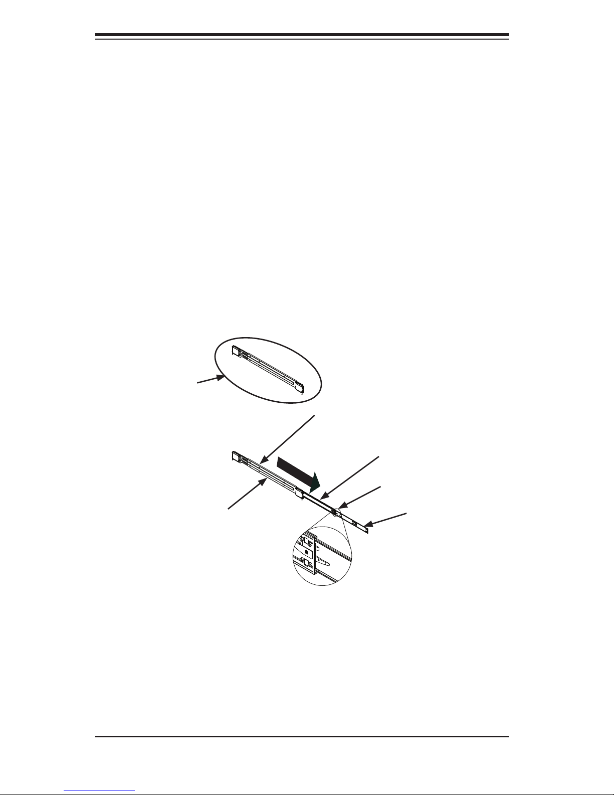
The chassis package includes two rail assemblies in the rack mounting kit. Each
assembly consists of three sections: An inner chassis rail that secures directly to
the chassis, an outer rail that secures to the rack, and a middle rail, which extends
from the outer rail. These assemblies are specifi cally designed for the left and right
side of the chassis.
Rail Assembly
(Shown with Rails
Retracted)
This Side Faces
Outward
Figure 2-1. Identifying the Outer, Middle and Inner Rails
Outer Rail
Middle Rail
Locking Tab
Inner Rail
(Left Rail Assembly Shown)
2-4
Page 19
Chapter 2: Server Installation
Locking Tabs
Each inner rail has a locking tab. This tab locks the chassis into place when installed
and pushed fully into the rack. These tabs also lock the chassis in place when fully
extended from the rack. This prevents the server from coming completely out of
the rack when when the chassis is pulled out for servicing.
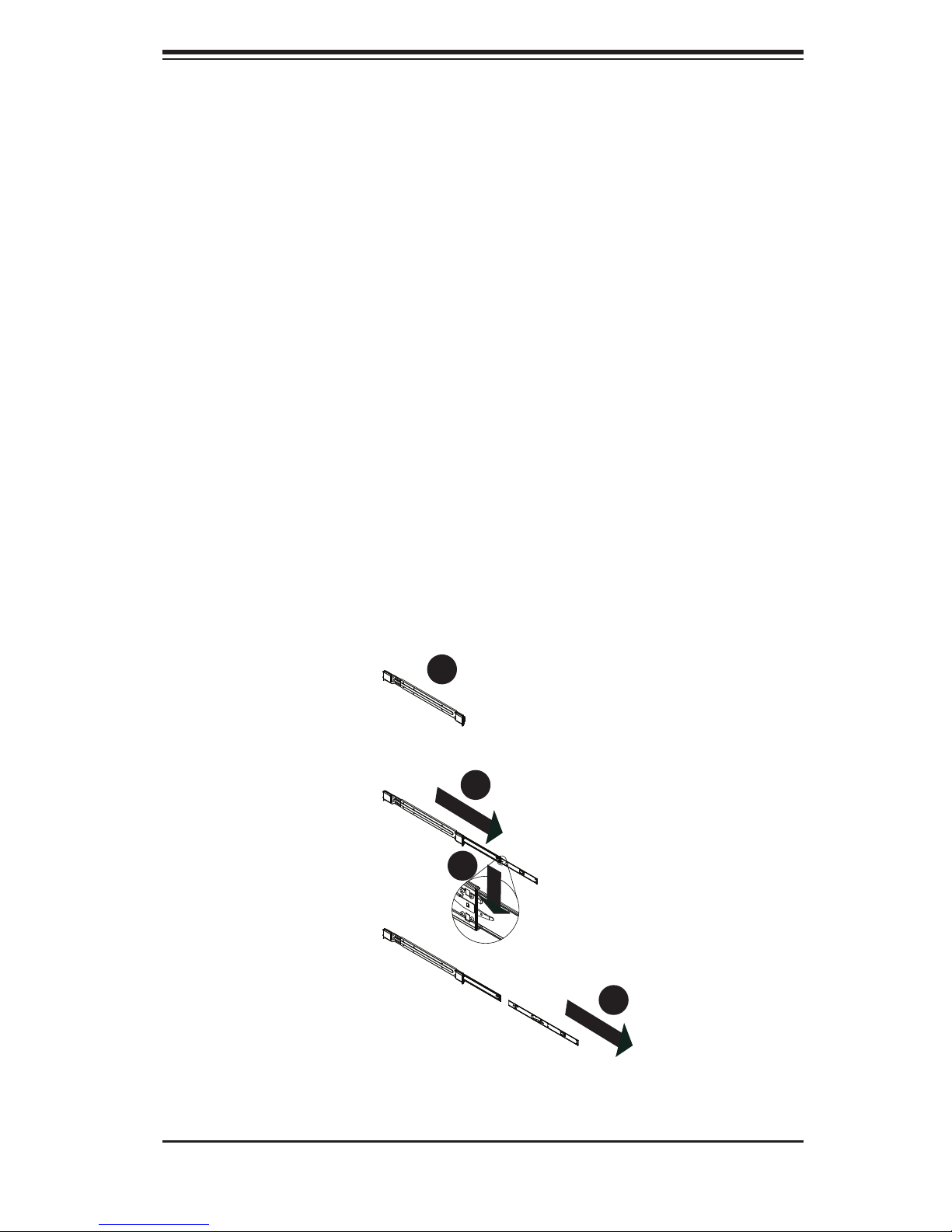
Releasing the Inner Rail
Releasing Inner Rail from the Outer Rails
1. Identify the left and right outer rail assemblies as described on the previous
page.
2. Pull the inner rail out of the outer rail until it is fully extended as illustrated
below.
3. Press the locking tab down to release the inner rail.
4. Repeat steps 1-3 for the remaining outer rail.
1
1
2
1
3
1
Figure 2-2. Extending and Releasing the Inner Rail
2-5
4
1
Page 20
SUPERSERVER 5037MC-H8TRF User's Manual
4
1
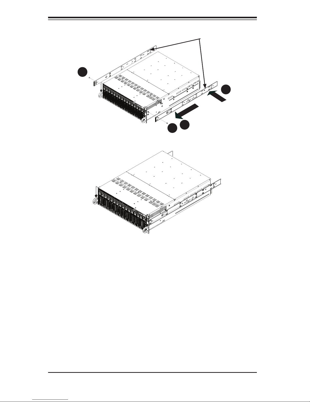
Figure 2-3. Installing the Inner Rails
Inner Rails
2
1
3
1
1
4
Figure 2-4. Inner Rails Installed on the Chassis
Installing The Inner Rails on the Chassis
Installing the Inner Rails
1. Confi rm that the left and right inner rails have been correctly identifi ed.
2. Place the inner rail fi rmly against the side of the chassis, aligning the hooks
on the side of the chassis with the holes in the inner rail.
3. Slide the inner rail forward toward the front of the chassis until the rail clicks
into the locked position, which secures the inner rail to the chassis.
4. Secure the inner rail to the chassis with the screws provided.
5. Repeat steps 1 through 4 above for the other inner rail.
2-6
Page 21
Chapter 2: Server Installation
1
1
4
1
2
1
3
1
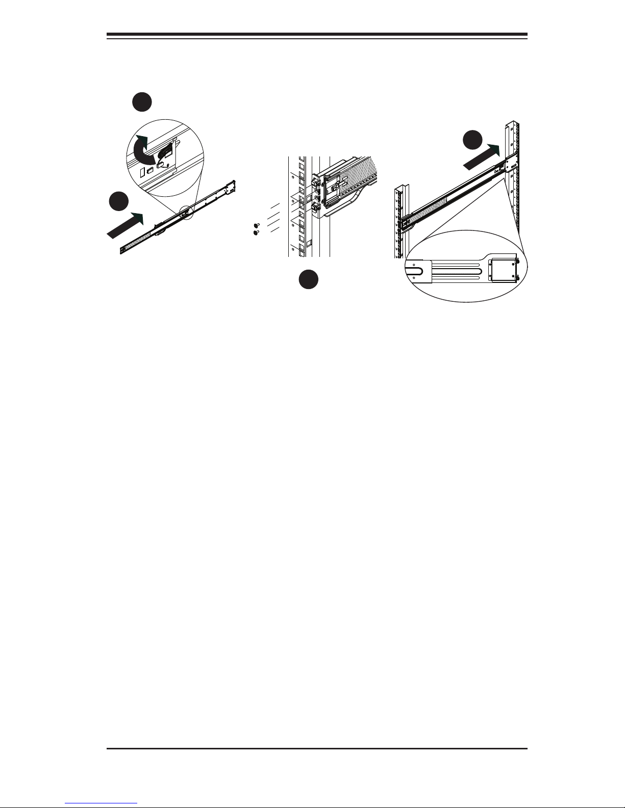
Figure 2-5. Extending and Releasing the Outer Rails
Installing the Outer Rails on the Rack
Installing the Outer Rails
1. Press upward on the locking tab at the rear end of the middle rail.
2. Push the middle rail back into the outer rail.
3. Hang the hooks of the front of the outer rail onto the slots on the front of
the rack. If necessary, use screws to secure the outer rails to the rack, as
illustrated above.
4. Pull out the rear of the outer rail, adjusting the length until it fi ts within the
posts of the rack.
5. Hang the hooks of the rear portion of the outer rail onto the slots on the rear
of the rack. If necessary, use screws to secure the rear of the outer rail to the
rear of the rack.
6. Repeat steps 1-5 for the remaining outer rail.
2-7
Page 22
SUPERSERVER 5037MC-H8TRF User's Manual
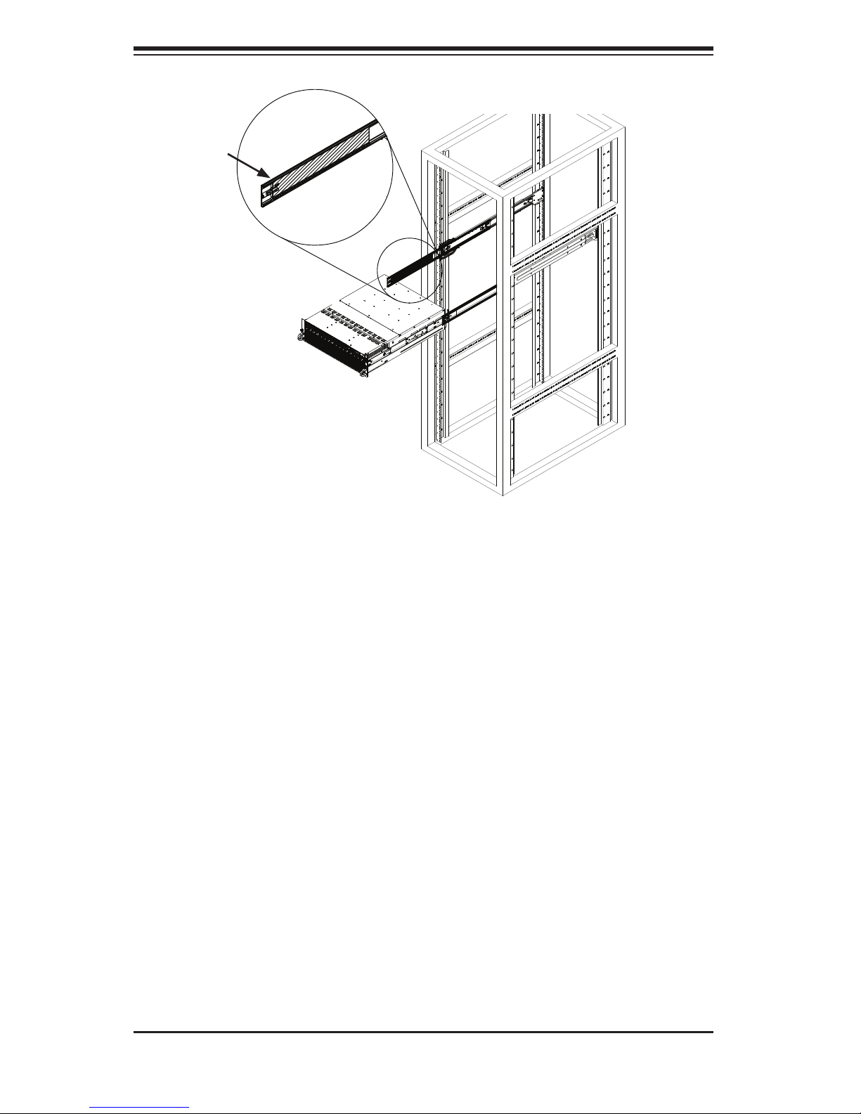
Ball-Bearing
Shuttle
Figure 2-6. Installing the Chassis into a Rack
Standard Chassis Installation
1. Confi rm that the inner rails are properly installed on the chassis.
2. Confi rm that the outer rails are correctly installed on the rack.
3. Pull the middle rail out from the front of the outer rail and make sure that the
ball-bearing shuttle is at the front locking position of the middle rail.
4. Align the chassis inner rails with the front of the middle rails.
5. Slide the inner rails on the chassis into the middle rails, keeping the pressure
even on both sides, until the locking tab of the inner rail clicks into the front of
the middle rail, locking the chassis into the fully extended position.
6. Depress the locking tabs of both sides at the same time and push the chassis
all the way into the rear of the rack.
7. If necessary for security purposes, use screws to secure the chassis handles
to the front of the rack.
2-8
Page 23
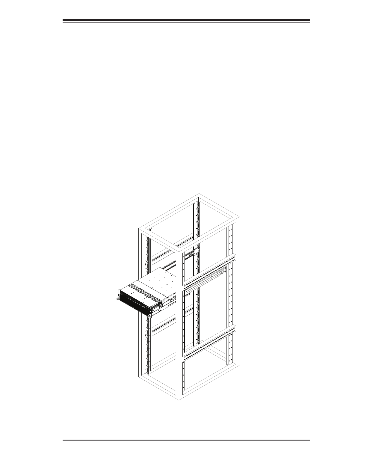
Chapter 2: Server Installation
Optional Quick Installation Method
The following quick installation method may be used to install the chassis onto a
rack.
1. Install the inner rails on the chassis as previously described on page 2-6.
2. Install the whole rail assembly onto the rack as described on page 2-7.
3. Release the inner rail without retracting the middle rail.
4. Install the chassis onto the middle rail as described in the previous section.
Figure 2-7. Installing the Chassis into a Rack
2-9
Page 24

SUPERSERVER 5037MC-H8TRF User's Manual
2-5 Checking the Motherboard Setup
After setting up the the system, you may need to open the unit to make sure all the
connections have been made.
Note: Before operating the system for the fi rst time, it is important to remove the
protective fi lm covering the ventilation openings on the top of the chassis. These
vents provide proper ventilation and cooling for the system.
Removing the Chassis Cover and Protective Film
1. Disconnect the chassis from any power source.
2. Remove the three screws that secure the top cover onto the chassis as il-
lustrated in Figure 2-8.
3. Lift the top cover up and off the chassis.
4. Peel off the protective fi lm covering the top cover and the top of the chassis
5. Check that all ventilation openings on the top cover and the top of the chassis
are clear and unobstructed.
Checking the Components and Setup
1. You may have a processor already installed into each of the motherboards.
Each processor should have its own heatsink attached. See Chapter 5 for
instructions on processor and heatsink installation.
2. Your server may have come with system memory already installed. Make
sure all DIMMs are fully seated in their slots. For details on adding system
memory, refer to Chapter 5.
3. If desired, you can install add-on cards to the system. See Chapter 5 for
details on installing PCI add-on cards.
4. Make sure all power and data cables are properly connected and not blocking
the chassis airfl ow. See Chapter 5 for details on cable connections.
2-10
Page 25
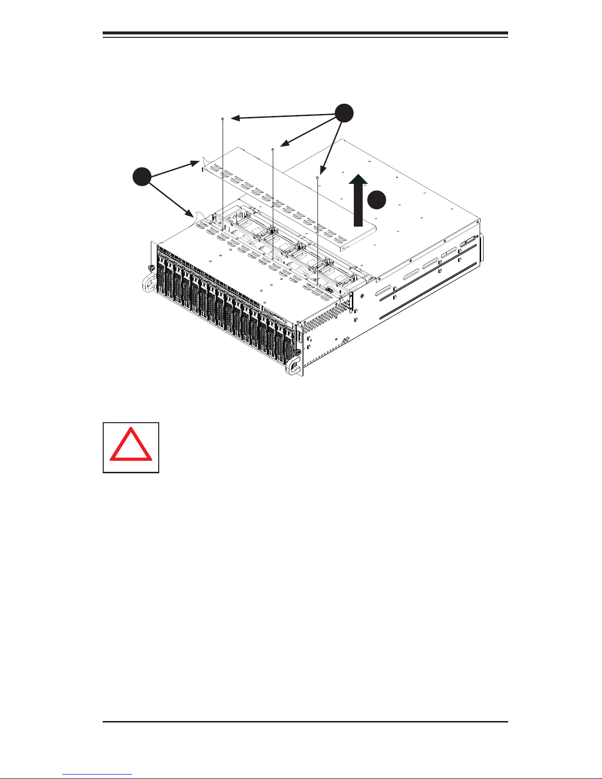
Remove Film
!
From Vents
4
1
Chapter 2: Server Installation
Figure 2-8. Accessing the Inside of the System
Remove Three
2
1
Screws
3
1
Warning: Except for short periods of time, do NOT operate the server
without the cover in place. The chassis cover must be in place to allow
proper airfl ow and prevent overheating.
2-11
Page 26
SUPERSERVER 5037MC-H8TRF User's Manual
!
2-6 Preparing to Power On
Checking the Drives
1. Depending upon your system's confi guration, your system may have hard
drives already installed. If you need to install hard drives, please refer to
Chapter 6.
Checking the Airfl ow
1. Airfl ow is provided by four 8-cm hot-swap system fans working in conjunction
with air shrouds on each node. The system component layout was carefully
designed to promote suffi cient airfl ow through the chassis.
2. Note that all power and data cables have been routed in such a way that they
do not block the airfl ow generated by the fans. Keep this in mind when you
reroute them after working on the system.
Providing Power
1. Plug the AC power cords into a high-quality power strip that offers protection
from electrical noise and power surges.
2. It is recommended that you use an uninterruptible power supply (UPS).
3. Finally, depress the power on button on the front of the chassis.
Warning: Except for short periods of time while swapping nodes, do not
operate the server with the node bays empty. In the unlikely event of a
node failure, remove the failed node and replace it with the dummy node
that was included with the system..
2-12
Page 27

Chapter 3: System Interface
Chapter 3
System Interface
3-1 Overview
LEDs are included on the control panel, the serverboard nodes and on the drive
carriers to keep you constantly informed of the overall status of the system. The
SC938 features four separate control panels on the handles of the chassis to
control the nodes.
This chapter explains the meanings of all LED indicators and the appropriate re-
sponse you may need to take.
3-2 Control Panel Buttons
Power Button/LED
The main power button on the control panel functions as both an on/off switch and
as an LED. The LED illuminates green when powered-on and is not illuminated
when powered-off.
• A quick press of less than fi ve seconds will sequentially power-on all of the
nodes in order from one to eight.
• Pressing the button for longer than fi ve seconds will sequentially power-
down the nodes in order from one to eight.
Turning off system power with this button removes the main power, but keeps
standby power supplied to the system. Therefore, you must completely unplug
system from any power source before servicing the chassis. This does not apply
to hot-swappable hard drives, serverboard nodes and system fans.
3-1
Page 28
SUPERSERVER 5037MC-H8TRF User's Manual
3-3 LEDs
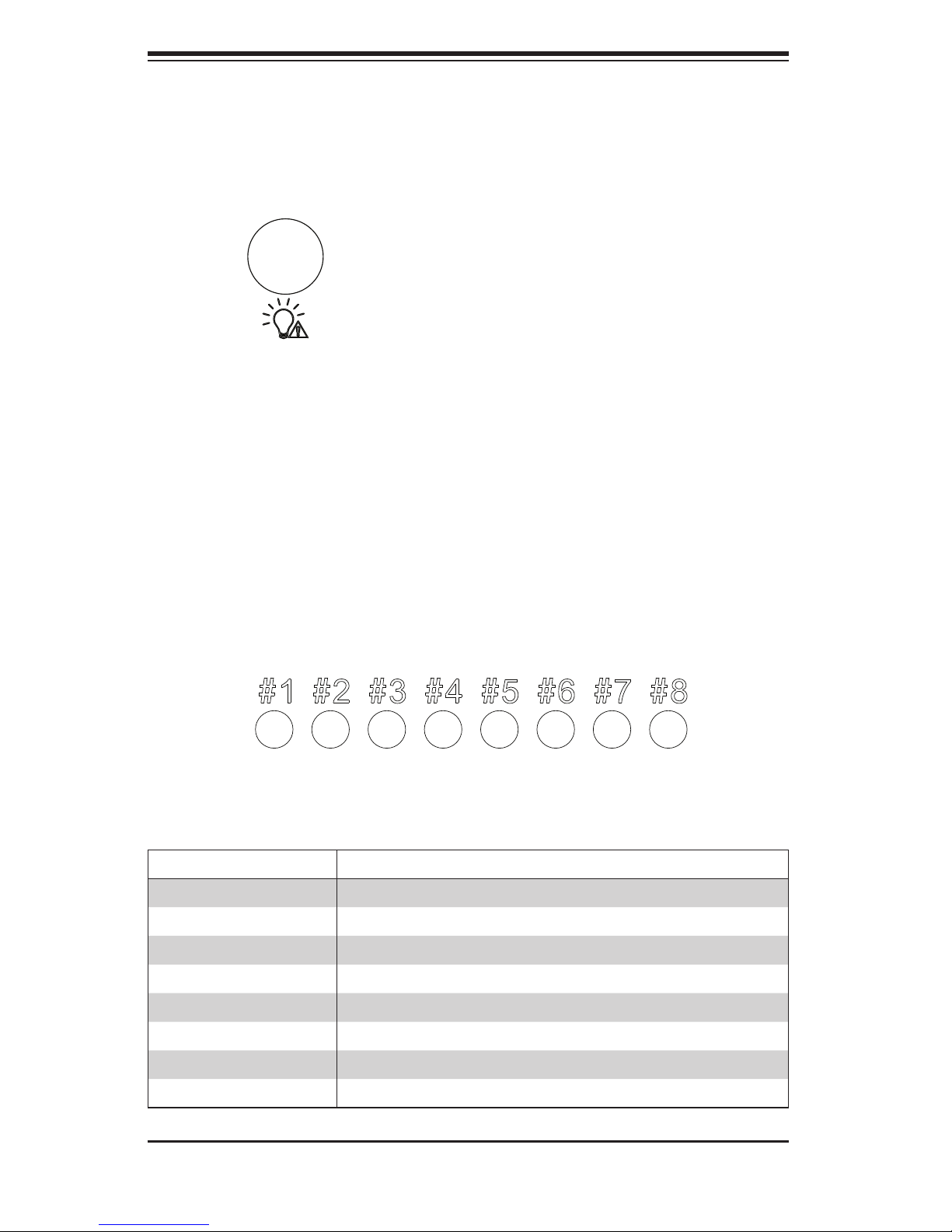
Power Failure LED
This red LED is illuminated only when a power failure occurs. The LED will illuminate
when any node is powered-on and one of the power supplies fails. This LED is off
during normal operation.
Node Status LEDs
The SC938 control panel features eight numbered node status LEDs, which indicate
the status of each serverboard node.
Figure 3-1. Node Status LEDs
LED Appearance Description
Solid Green The node is powered on and operating normally
Blinking Green The node is in the process of shutting down
Solid Red The node is detecting an overheated condition
1Hz Blinking Red The node is detecting a fan failure
.25Hz Blinking Red The node is detecting a power failure
Solid Blue The node local UID is on
1Hz Blinking Blue The node remote UID is on
No Illumination The node is powered-down
3-2
Page 29
Chapter 3: System Interface
3-4 Hard Drive Carrier LEDs
The hard drives ued in the SC938 chassis are installed in drive carriers. Each drive
carrier has two LEDs located on the front of the carrier.
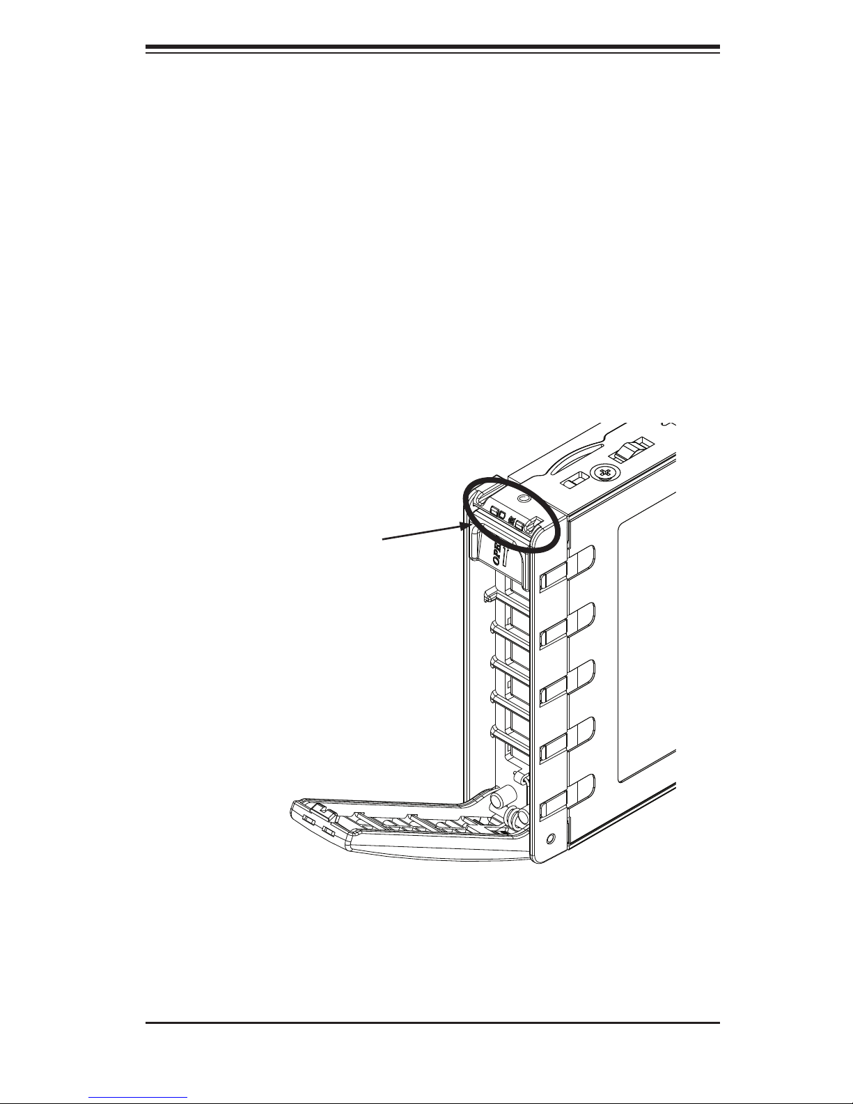
• Green: Each drive carrier has a green LED. When illuminated, this LED indicates
drive activity. A connection to the SATA backplane enables this LED to blink on
and off when that particular drive is being accessed.
• Red: Indicates a drive failure. If one of the drives fail, you should also be notifi ed
by your system management software.
Figure 3-2. Hard Drive Carrier LEDs
Hard Drive Carrier LEDs
3-5 Node LEDs
Individual LEDS are located on the back of each serverboard node on the rear of
the chassis.
3-3
Page 30
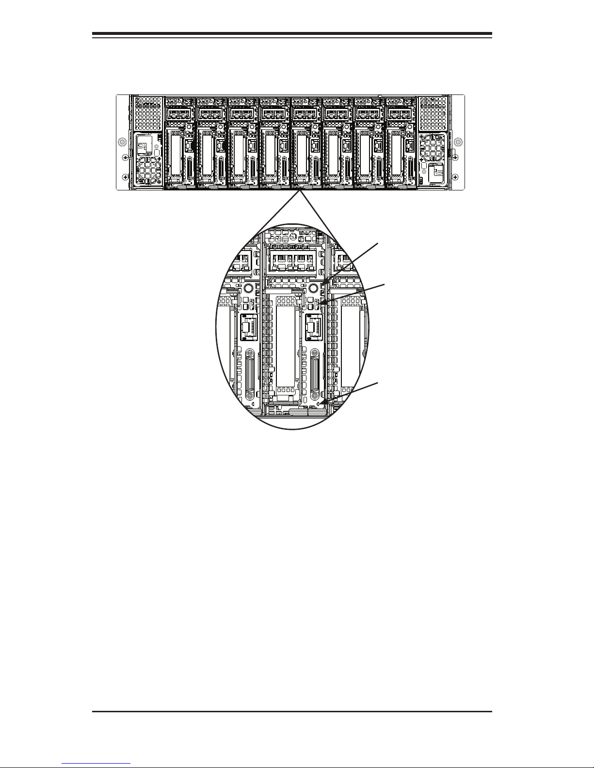
SUPERSERVER 5037MC-H8TRF User's Manual
Figure 3-3. Rear Node LED Indicators
Power Button
and LED
(Green)
UIO Button
and LED
(Blue)
Failure LED
(Red)
Power Button and LED
This button will power on the node individually. It is illuminated green when the node
is powered on, it is off (unilluminated ) when the node is powered off.
UIO Button and LED
This button is used to identify the node within the system. It is illuminated blue when
activated, it is off when inactive.
Failure LED
This LED is illuminated red when a failure has occurred and off during normal opera-
tion. If illuminated, check that the two corresponding hard drives are fully inserted
into their bays with their handles completely pushed in. Check also that the fan is
operating properly and that the node is fully inserted into its bay.
3-4
Page 31
Chapter 4: System Safety
!
Chapter 4
System Safety
4-1 Electrical Safety Precautions
Basic electrical safety precautions should be followed to protect yourself from harm
and the SuperServer 5037MC-H8TRF from damage:
• Be aware of the locations of the power on/off switch on the chassis as well
as the room's emergency power-off switch, disconnection switch or electrical
outlet. If an electrical accident occurs, you can then quickly remove power from
the system.
• Do not work alone when working with high voltage components.
• Power should always be disconnected from the system when removing or in-
stalling main system components, such as the motherboard, memory modules
and fl oppy drive. When disconnecting power, you should fi rst power down the
system with the operating system fi rst and then unplug the power cords of all
the power supply units in the system.
• When working around exposed electrical circuits, another person who is familiar
with the power-off controls should be nearby to switch off the power if neces-
sary.
• Use only one hand when working with powered-on electrical equipment. This
is to avoid making a complete circuit, which will cause electrical shock. Use
extreme caution when using metal tools, which can easily damage any electrical
components or circuit boards they come into contact with.
• Do not use mats designed to decrease static electrical discharge as protection
from electrical shock. Instead, use rubber mats that have been specifi cally
designed as electrical insulators.
• The power supply power cords must include a grounding plug and must be
plugged into grounded electrical outlets.
4-1
Page 32
SUPERSERVER 5037MC-H8TRF User's Manual
!
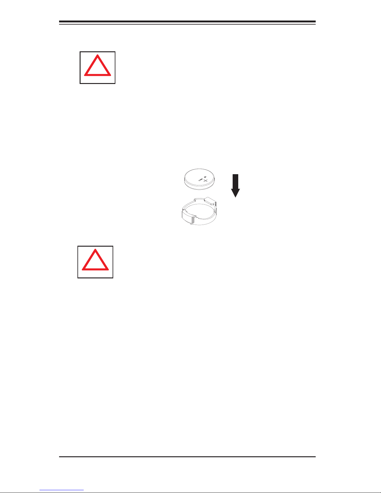
• Motherboard Battery: CAUTION - There is a danger of explosion if the onboard
battery is installed upside down, which will reverse its polarites (see Figure 4-1).
This battery must be replaced only with the same or an equivalent type recom-
mended by the manufacturer (CR2032). Dispose of used batteries according to
the manufacturer's instructions.
• DVD-ROM Laser: CAUTION - this server may have come equipped with a
DVD-ROM drive. To prevent direct exposure to the laser beam and hazardous
radiation exposure, do not open the enclosure or use the unit in any uncon-
ventional way.
• Mainboard replaceable soldered-in fuses: Self-resetting PTC (Positive Tempera-
ture Coeffi cient) fuses on the mainboard must be replaced by trained service
technicians only. The new fuse must be the same or equivalent as the one
replaced. Contact technical support for details and support.
4-2 General Safety Precautions
Follow these rules to ensure general safety:
• Keep the area around the SuperServer 5037MC-H8TRF clean and free of
clutter.
• The SuperServer 5037MC-H8TRF weighs approximately 62.2 lbs. (28.3 kg)
when fully loaded. When lifting the system, two people at either end should lift
slowly with their feet spread out to distribute the weight. Always keep your back
straight and lift with your legs.
• Place the chassis top cover and any system components that have been re-
moved away from the system or on a table so that they won't accidentally be
stepped on.
• While working on the system, do not wear loose clothing such as neckties and
unbuttoned shirt sleeves, which can come into contact with electrical circuits or
be pulled into a cooling fan.
• Remove any jewelry or metal objects from your body, which are excellent metal
conductors that can create short circuits and harm you if they come into contact
with printed circuit boards or areas where power is present.
4-2
Page 33
Chapter 4: System Safety
!
• After accessing the inside of the system, close the system back up and secure
it to the rack unit with the retention screws after ensuring that all connections
have been made.
4-3 ESD Precautions
Electrostatic Discharge (ESD) is generated by two objects with different electrical
charges coming into contact with each other. An electrical discharge is created to
neutralize this difference, which can damage electronic com ponents and printed
circuit boards. The following measures are generally suffi cient to neutralize this
difference before contact is made to protect your equipment from ESD:
• Use a grounded wrist strap designed to prevent static discharge.
• Keep all components and printed circuit boards (PCBs) in their antistatic bags
until ready for use.
• Touch a grounded metal object before removing the board from the antistatic
bag.
• Do not let components or PCBs come into contact with your clothing, which may
retain a charge even if you are wearing a wrist strap.
• Handle a board by its edges only; do not touch its components, peripheral chips,
memory modules or contacts.
• When handling chips or modules, avoid touching their pins.
• Put the motherboard and peripherals back into their antistatic bags when not
in use.
• For grounding purposes, make sure your computer chassis provides excellent
conductivity between the power supply, the case, the mounting fasteners and
the motherboard.
4-3
Page 34
SUPERSERVER 5037MC-H8TRF User's Manual
!
!
4-4 Operating Precautions
Care must be taken to assure that the chassis cover is in place when the 5037MC-
H8TRF is operating to assure proper cooling. Out of warranty damage to the system
can occur if this practice is not strictly followed.
Figure 4-1. Installing the Onboard Battery
LITHIUM BATTERY
BATTERY HOLDER
Please handle used batteries carefully. Do not damage the battery in any way; a
damaged battery may release hazardous materials into the environment. Do not
discard a used battery in the garbage or a public landfi ll. Please comply with the
regulations set up by your local hazardous waste management agency to dispose
of your used battery properly.
4-4
Page 35

Chapter 5: Advanced Motherboard Setup
Chapter 5
Advanced Motherboard Setup
This chapter covers the steps required to install the motherboard modules into the
chassis, connect the data and power cables and install add-on cards. All mother-
board jumpers and connections are also described. A layout and quick reference
chart are included in this chapter for your reference. Remember to completely
close the chassis when you have fi nished working with the server to better cool
and protect the system.
5-1 Handling the Motherboard
Electrostatic Discharge (ESD) can damage electronic com ponents. To prevent dam-
age to any printed circuit boards (PCBs), it is important to handle them very carefully
(see previous chapter). To prevent the motherboard from bending, keep one hand
under the center of the board to support it when handling. The following measures
are generally suffi cient to protect your equipment from electric static discharge.
Precautions
• Use a grounded wrist strap designed to prevent Electrostatic Discharge
(ESD).
• Touch a grounded metal object before removing any board from its antistatic
bag.
• Handle a board by its edges only; do not touch its components, peripheral chips,
memory modules or gold contacts.
• When handling chips or modules, avoid touching their pins.
• Put the motherboard, add-on cards and peripherals back into their antistatic
bags when not in use.
• For grounding purposes, make sure your computer chassis provides excellent
conductivity between the power supply, the case, the mounting fasteners and
the motherboard.
5-1
Page 36
SUPERSERVER 5037MC-H8TRF User's Manual
Unpacking
The motherboard is shipped in antistatic packaging to avoid electrical static
discharge. When unpacking the board, make sure the person handling it is static
protected.
5-2 Motherboard Installation
The X9SCD-F motherboards have been preinstalled into carriers to simplify install-
ing and removing the nodes from the SC938H-R1620B chassis. The motherboards
should remain in these carriers at all times. If a failed node needs to be returned
for repair or replacement, the motherboard is to be shipped assebled in its carrier
and not by itself. See Chapter 6 for instructions on installing and removing the
motherboard nodes from the chassis.
5-3 Connecting Cables
The 5037MC-H8TRF server was designed as a cableless system. As a result,
all power and data connections to the motherboard nodes are made whenever a
node is installed into its bay in the chassis. This covers the main power connec-
tion, the control panel connections and the data and power connections for the
SATA drives.
5-4 I/O Ports
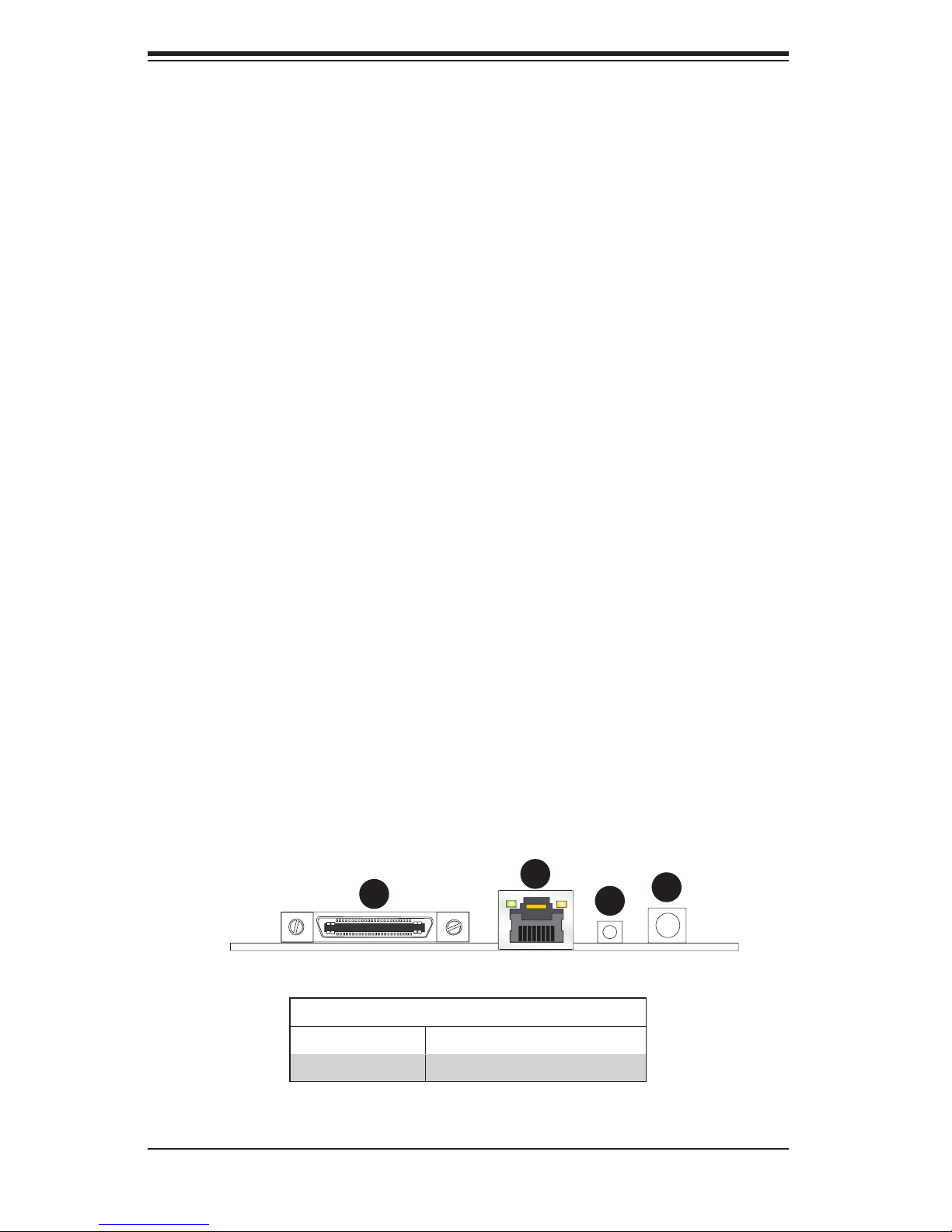
The I/O ports are located at the back of the motherbord node. See Figure 5-1 below
for the colors and locations of the various I/O ports.
Figure 5-1. I/O Ports
2
1
3
4
1 KVM Port 3 UID Button
2 IPMI Port 4 Power Button and LED
I/O Ports
5-2
Page 37
Chapter 5: Advanced Motherboard Setup
5-5 Processor and Heatsink Installation
Notes:
• When changing the CPU in a node, always power down the node fi rst and
remove it from the chassis. Make sure that you install the CPU into its socket
before you install the CPU heatsink.
• If you buy a CPU separately, make sure that you use an Intel-certifi ed multi-
directional heatsink only.
• When receiving a motherboard without a processor pre-installed, make sure that
the plastic CPU socket cap is in place and none of the socket pins are bent;
otherwise, contact your retailer immediately.
• Refer to the Supermicro web site for updates on CPU support.
Installing an LGA1155 Processor
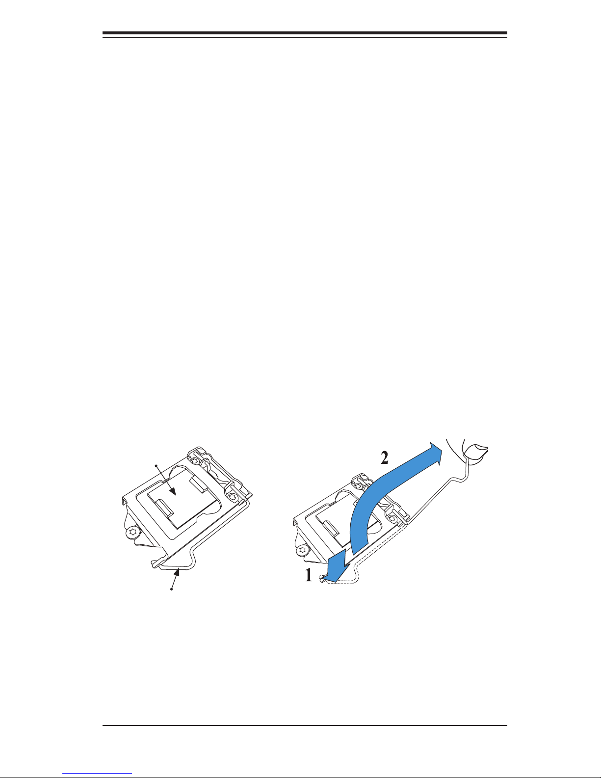
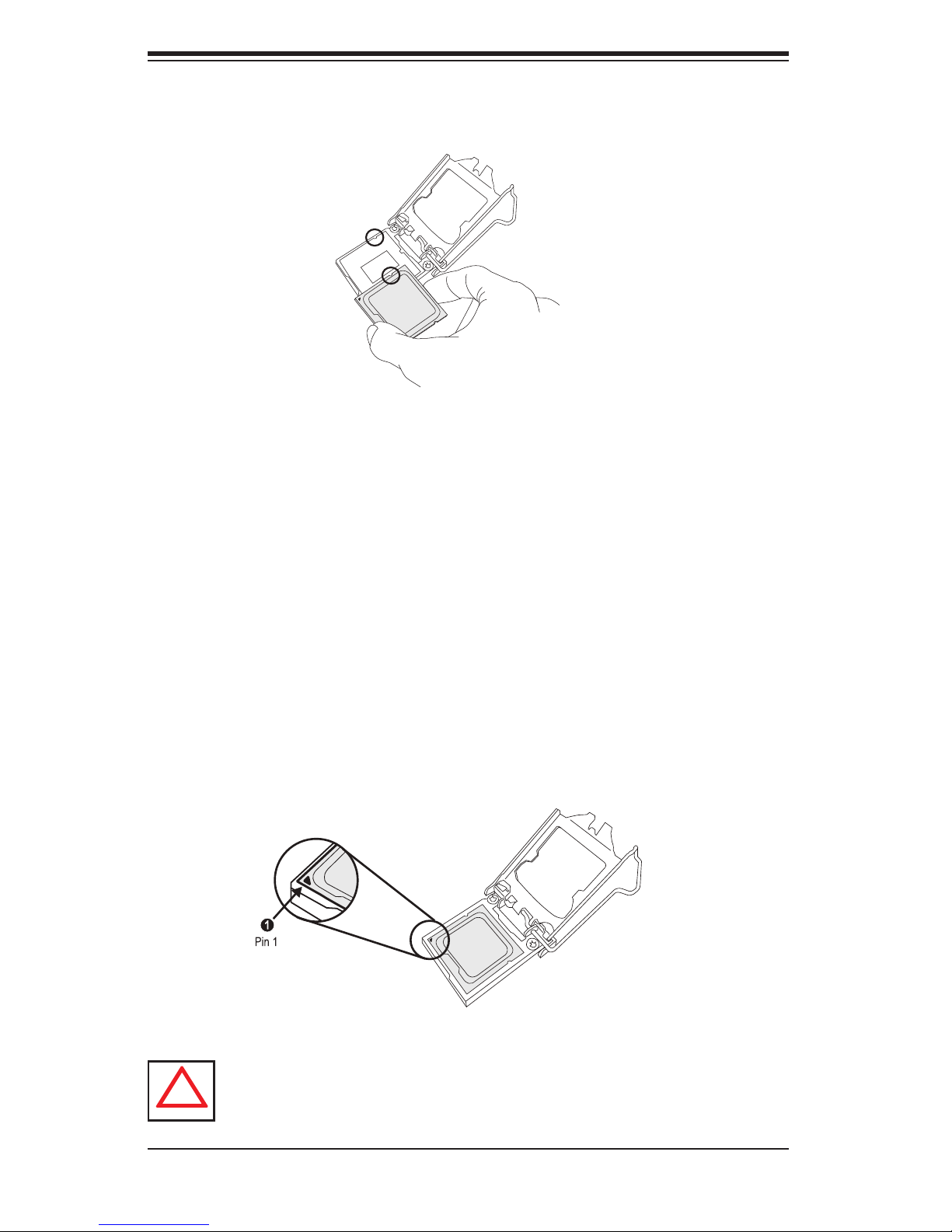
1. Press the load lever to release the load plate, which covers the CPU socket,
from its locked position.
2. Gently lift the load lever to open the load plate. Remove the plate cap.
Load Plate
Load Lever
5-3
Page 38
SUPERSERVER 5037MC-H8TRF User's Manual
!
3. Use your thumb and your index fi nger to hold the CPU at the top center edge
and the bottom center edge of the CPU.
4. Align the CPU key (the semi-circle cutouts) against the socket keys. Once
aligned, carefully lower the CPU straight down to the socket. (Do not drop the
CPU on the socket. Do not move the CPU horizontally or vertically.
Do not rub the CPU against the surface or against any pins of the socket to
avoid damage to the CPU or the socket.)
With the CPU inside the socket, inspect the four corners of the CPU to make
sure that the CPU is properly installed.
5. Use your thumb to gently push the load lever down to the lever lock.
Save the plastic PnP cap. The motherboard must be shipped with the PnP
cap properly installed to protect the CPU socket pins. Shipment without the
PnP cap properly installed will cause damage to the socket pins.
Warning: The CPU will only seat inside the socket in one direction. Make
sure it is properly inserted before closing the load plate. If it doesn't close
properly, do not force it as it may damage your CPU. Instead, open the load
plate again and double-check that the CPU is aligned properly.
5-4
Page 39
Chapter 5: Advanced Motherboard Setup
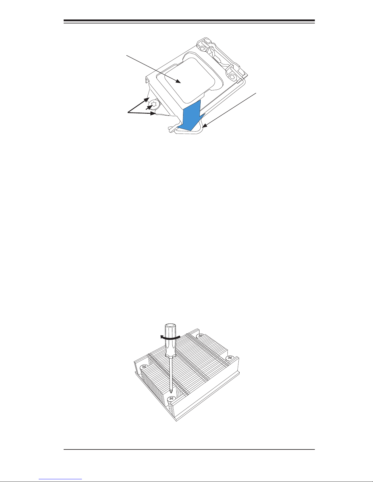
CPU properly
installed
Load lever locked
into place.
B
A
Make sure "A"
points are under B
Installing a Heatsink
1. With the node removed, remove the air shroud as described in Section 6-7.
2. Do not apply any thermal grease to the heatsink or the CPU die; the required
amount has already been applied.
3. Place the heatsink on top of the CPU so that the four mounting holes are
aligned with those on the motherboard and the heatsink bracket underneath.
4. Screw in two diagonal facing screws until just snug (do not over-tighten the
screws to avoid possible damage to the CPU.)
5. Finish the installation by fully tightening all four screws.
6. Reverse the order of this procedure to remove a heatsink.
Figure 5-2. Installing a Heatsink
5-5
Page 40
SUPERSERVER 5037MC-H8TRF User's Manual
!
5-6 Installing Memory
CAUTION! Exercise extreme care when installing or removing DIMM
modules to prevent any possible damage.
How to Install Memory
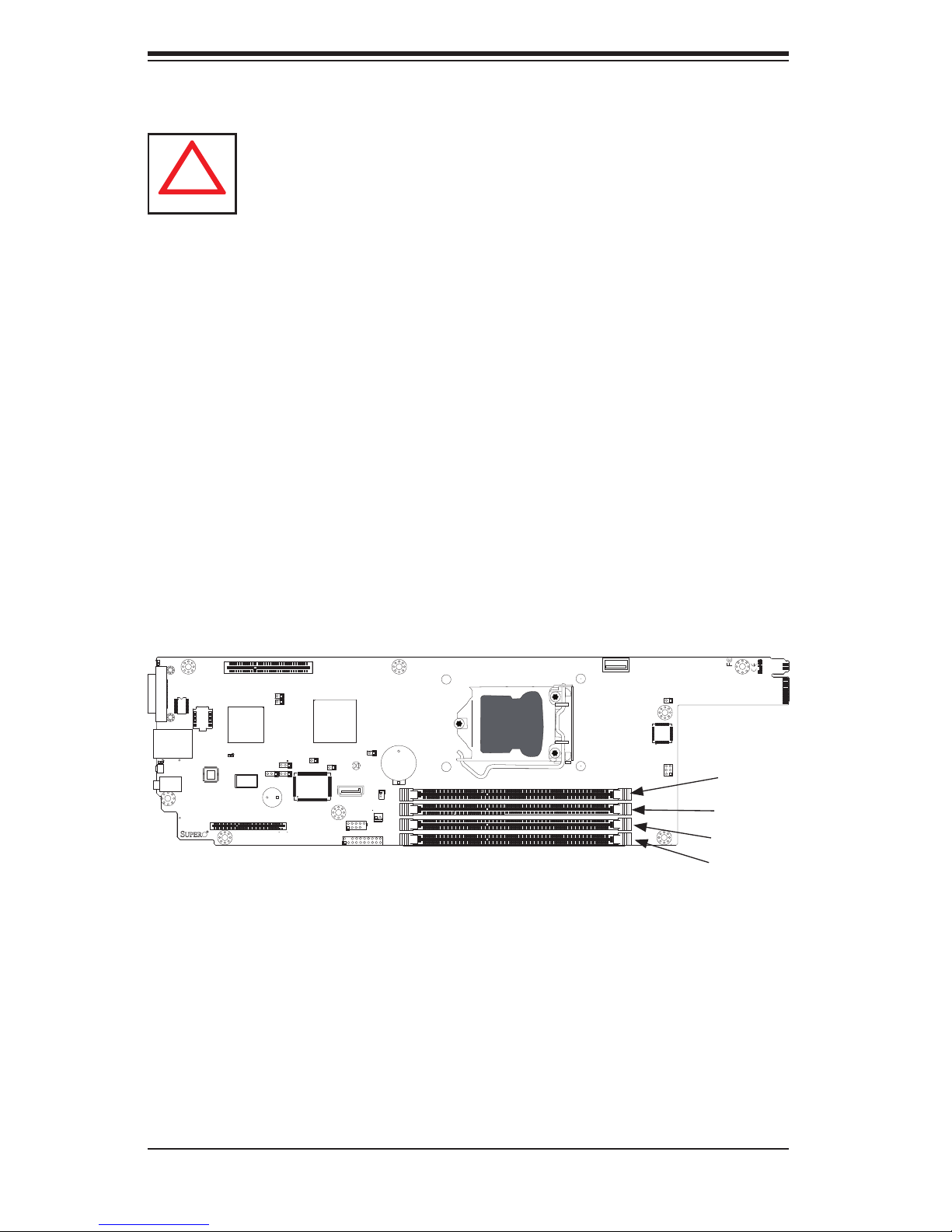
1. Insert the desired number of DIMMs into the memory slots, starting with
DIMM1A, then DIMM2A, DIMM1B, DIMM2B. Pay attention to the notch along
the bottom of the module to prevent incorrect installation.
2. Insert each DIMM module vertically push down until it and snaps into place.
Repeat to install more memory, if needed. See instructions on the next page.
Memory Support
Each X9SCD-F supports up to 32GB of ECC DDR3 UDIMM memory (1066/1333
MHz) in four DIMM slots. Please refer to the product page on our web site for pos-
sible updates to memory support.
Installing and Removing DIMMs
C
MICRO-LP PCI-E 3.0 X8
SLOT1 PCI-E 3.0 X8
JI2C1
1
JPME2
1-2RST
JWD1
2-3NMI
JPB1
1-2ENAB
2-3DISB
JPG1
1-2ENAB
2-3DISB
+
JPME1
JBT1
CMOS
CLEAR
1
JWF1
I-SATA4
JPK1
1
1
USB1
JTPM1
CPU1
P1-DIMM1A
P1-DIMM1B
P1-DIMM2A
B1
P1-DIMM2B
DIMM1
DIMM2
DIMM3
DIMM4
Image rotated 90
◦
1
JKVM1
UID
SW1 SW2
+
LAN1
J4
A
PWR
X9SCD-F
J2
USB2
1
U1
JP2
DIMM1A
DIMM1B
DIMM2A
DIMM2B
5-6
Page 41
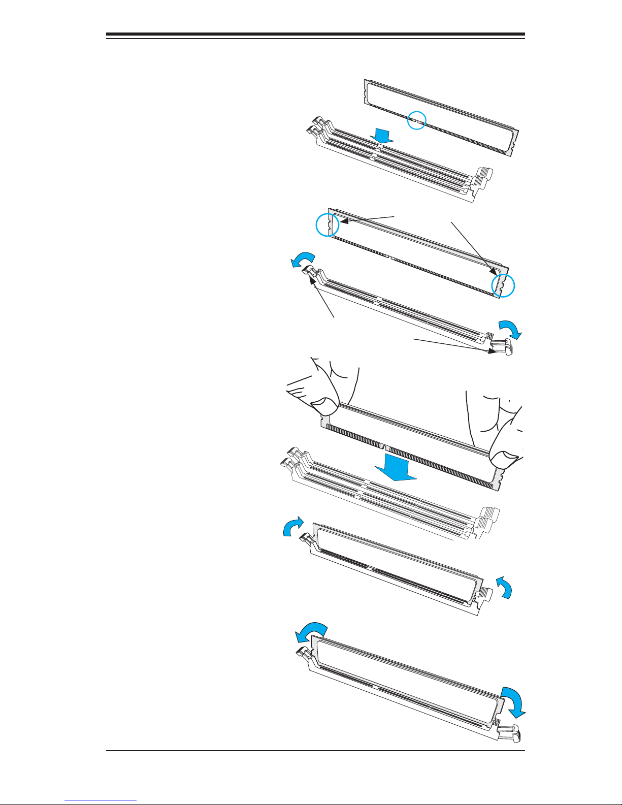
Installing and Removing DIMMs
Position the DIMM module's
bottom key so that it aligns
with the receptive point on
the slot.
Chapter 5: Advanced Motherboard Setup
Notches
Push a lock/release tab to the
release position. Make sure
that the side notches of the
DIMM module aligns with the
lock/release tab of the slot as
it is pressed in.
Insert the DIMM module verti-
cally and press down until the
module snaps into place.
Release
Release
Lock/Release Tabs
Press Down
When the module is prop-
erlly inserted, the lock/re-
lease tabs will automatically
secure the DIMM module,
locking it into place.
To Remove:
Use your thumbs to gently
push the lock/release tabs
near both ends of the module.
This should release it from the
slot. Pull the DIMM module
upwards.
Lock
Release
5-7
Lock
Release
Page 42
SUPERSERVER 5037MC-H8TRF User's Manual
Guidelines for Populating Memory
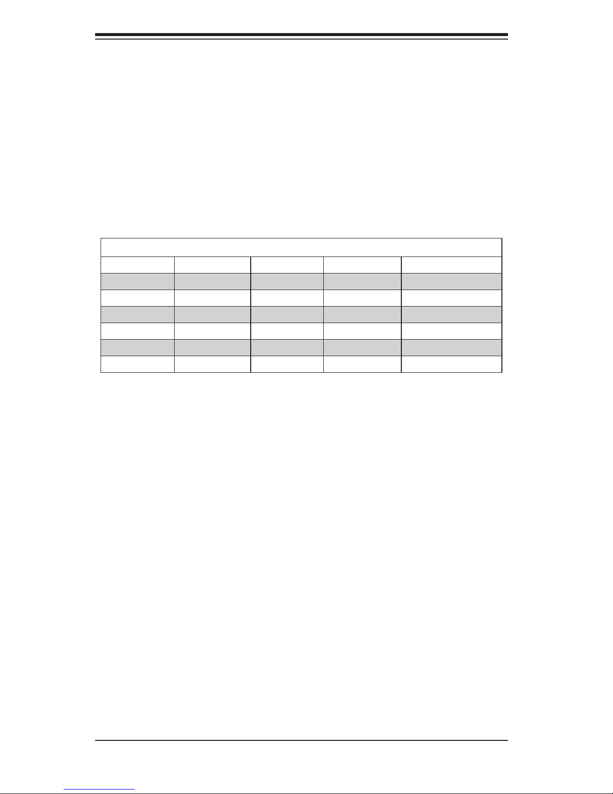
When installing memory modules, the DIMM slots should be populated in the fol-
lowing order: DIMM1A, DIMM2A, DIMM1B and DIMM2B.
• Always use DDR3 DIMM modules of the same size, type and speed.
• Mixed DIMM speeds can be installed. However, all DIMMs will run at the speed
of the slowest DIMM.
• Although the motherboard can support one or three DIMM modules installed,
memory should be installed in pairs for best performance.
Recommended Population (Balanced)
DIMM2B Slot DIMM2A Slot DIMM1B Slot DIMM1A Slot Total System Memory
2GB DIMM 2GB DIMM 4GB
2GB DIMM 2GB DIMM 2GB DIMM 2GB DIMM 8GB
4GB DIMM 4GB DIMM 8GB
4GB DIMM 4GB DIMM 4GB DIMM 4GB DIMM 16GB
8GB DIMM 8GB DIMM 16GB
8GB DIMM 8GB DIMM 8GB DIMM 8GB DIMM 32GB
5-7 Adding PCI Add-On Cards
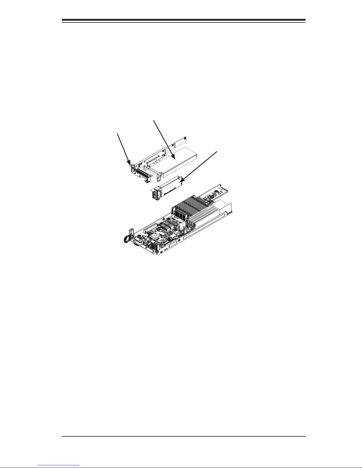
The 5037MC-H8TRF supports one low-profi le PCI card in each of the eight nodes.
To install an expansion card, follow the instructions below.
Installing an Add-on Card
1. Power-down the node using that node's individual power button and remove it
as described in Chapter 6.
2. Open the PCI slot clip and remove the PCI slot shield.
3. Open the PCI slot clip in the rear of the motherboard node.
4. Remove the PCI slot shield.
5. Insert the expansion card into the riser card which is pre-installed on the
motherboard (if desired the riser card may be removed from the motherboard
by removing the riser card screw)
6. Slide the expansion cards bracket into the PCI card slot and fi t it with the
opening in the rear of the node.
5-8
Page 43
Chapter 5: Advanced Motherboard Setup
7. Close the PCI card slot clip to secure the expansion card.
Note: The PCI slot shields protect the motherboard and its components from EMI
and aid in proper ventilation, so make sure there is always a shield covering each
unused slot.
Expansion Card
PCI Slot
Bracket
Riser Card
Figure 5-12: Installing the Expanion Card
Note: The node and motherboard shown above are examples. Your actual node
and motherboard may vary from those illustrated)
5-9
Page 44
SUPERSERVER 5037MC-H8TRF User's Manual
5-8 Motherboard Details
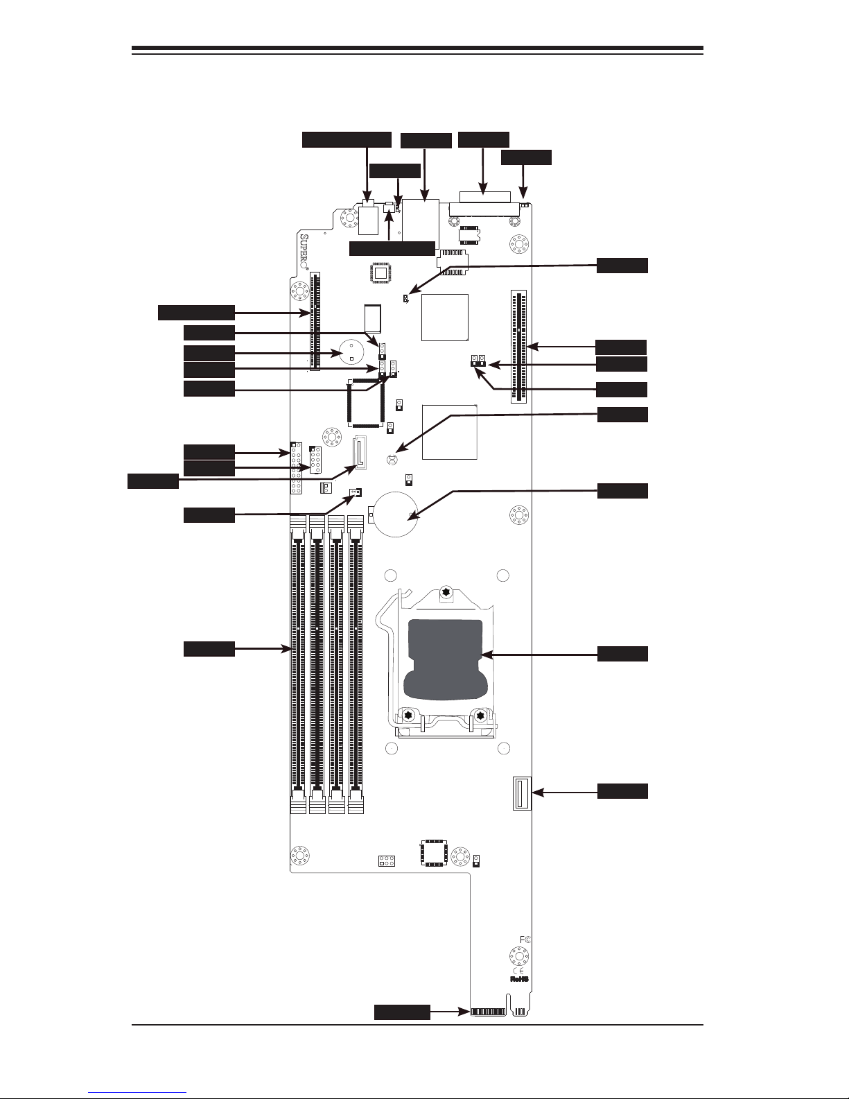
Figure 5-4. X9SCD-F Layout
PWR BTN/LED
UID LED
IPMI
JKVM1
LED5
I-SATA4
MICRO LP
JPB1
SPKR1
JPG1
JWD1
JTPM1
JUSB2
JWF1
SW1 SW2
PWR
X9SCD-F
UID
J4
A
UID BUTTON
J2
MICRO-LP PCI-E 3.0 X8
+
JTPM1
1
USB1
JPK1
1
DIMM4
DIMM3
JPB1
1-2ENAB
2-3DISB
JWD1
JPG1
1-2ENAB
2-3DISB
1-2RST
2-3NMI
JPME2
JBT1
CMOS
CLEAR
I-SATA4
JWF1
1
B1
DIMM1
DIMM2
P1-DIMM1A
P1-DIMM1B
P1-DIMM2A
P1-DIMM2B
JKVM1
LAN1
+
JI2C1
1
JPME1
CPU1
1
SLOT1 PCI-E 3.0 X8
C
LED4
SLOT1
JI2C1
JI2C2
JBT1
BATT
DIMM
JP2
IF +PWR
5-10
CPU
USB2
JUSB1
1
U1
Page 45
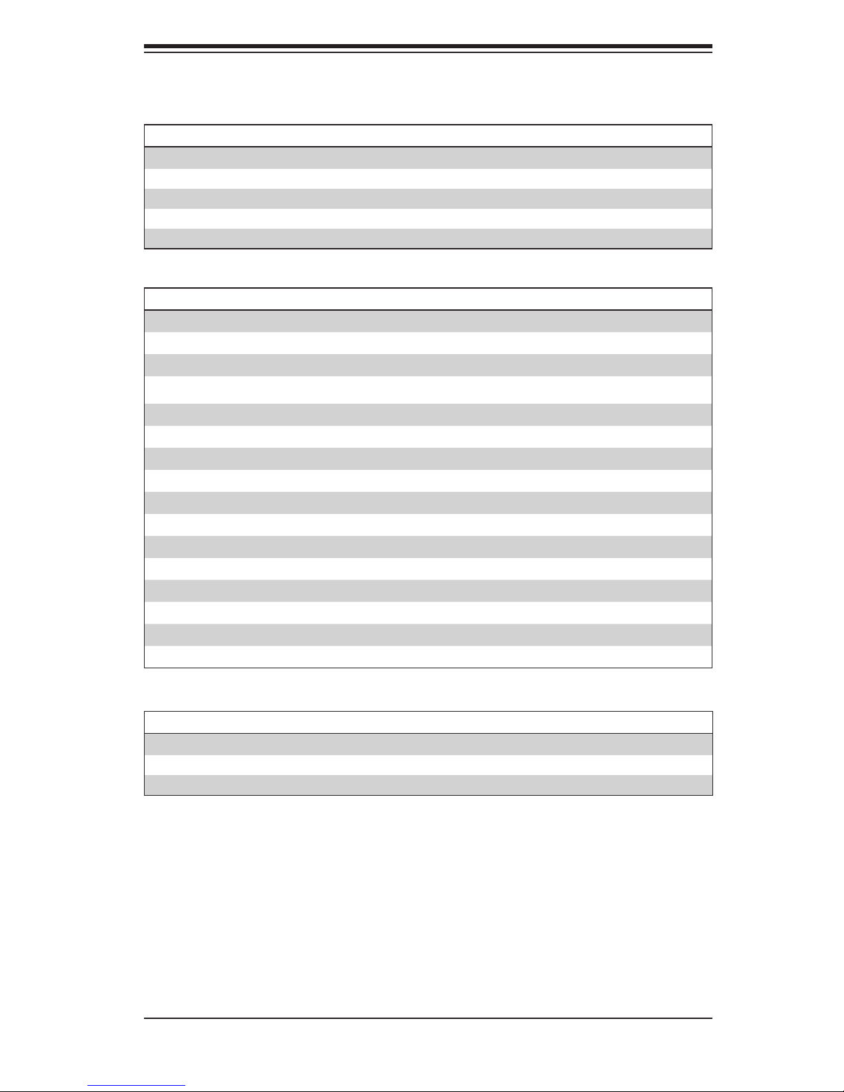
X9SCD-F Quick Reference
Chapter 5: Advanced Motherboard Setup
Jumper Description
JPB1 BMC Enable/Disable
JPG1 Onboard VGA Enable/Disable Pins 1-2 (Enabled)
JWD1 Watch Dog Timer RST/NMI Selection Pins 1-2 (Reset)
JBT1 CMOS Clear See Section 5-11
JI2C1, JI2C2 SMB to PCI Slots See Section 5-11
Connector Description
Micro LP Slot PCI-E 2.0 (Micro LP Slot & Slot 1)
SPKR1 Internal Speaker / Buzzer
JTPM1
JUSB2 USB Header
I-SATA4 Internal SATA Port
JWF1 SATA Disk On Module (DOM) Power Connector
DIMM DIMM Memory Slots
IF + PWR Back Panel Edge Connector (SATA/Power)
JUSB1 Internal (Type A) USB Port
CPU Socket H2 (LGA1155) for a single Xeon E3-1200 series CPU
BATT Onboard Battery
Slot1 PCI-E 2.0 x 8 Slot
JKVM1 USB / VGA / UART Interface
IPMI RJ45 IPMI Port
UID Button Unit ID Button
PWR BTN/LED Power Button and LED
Trusted Platform Module (TPM) Header
Default Setting
Pins 1-2 (Enabled)
LED Description
LED4 IPMI Heartbeat (Green: Blinking = Normal)
LED5 System Fail LED
UID LED Unit ID LED
5-11
Page 46
SUPERSERVER 5037MC-H8TRF User's Manual
5-9 Connector Defi nitions
IF + POWER
This edge connector, located on the opposite end of the motherboard from the I/O
back panel, is used to connect the motherboard to the backplane of the server
chassis. Through this connector, the motherboard will receive its power and com-
municate with the rest of the system (hard drives, warning lamps, etc).
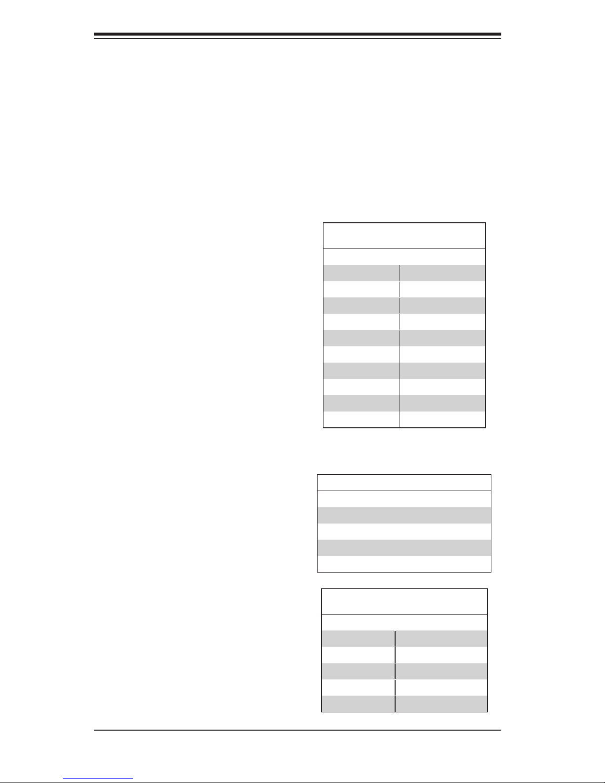
TPM Header
This header is used to connect a
Trusted Platform Module (TPM), that
is available from a third-party vendor.
A TPM is a security device that allows
encryption and authentication of hard
drives. It enables the motherboard to
deny access if the TPM associated
with the hard drive is not installed in
the system. See the table on the right
for pin defi nitions.
Universal Serial Bus (USB)
Three Universal Serial Bus ports (USB
2~3) are located on the on the mother-
board. Two of these are available on
a header, and one on a Type A con-
nector. There are also two ports (USB
0/1) available through the KVM port
(cables not included). See the tables
on the right for pin defi nitions.
Trusted Platform Module Header
Pin Defi nitions
Pin # Defi nition Pin # Defi nition
1 LCLK 2 GND
3 LFRAME 4 No Pin
5 LRESET 6 VCC5
7 LAD3 8 LAD2
9 VCC3 10 LAD1
11 LAD0 12 GND
13 RSV0 14 RSV1
15 SB3V 16 SERIRQ
17 GND 18 CLKRUN
19 LPCPD 20 RSV2
Type A USB Pin Defi nition
Pin# Defi nition Pin# Defi nition
1 +5V 5 +5V
2 USB_PN 6 USB_PN
3 USB_PP 7 USB_PP
4 Ground 8 Ground
USB Header
Pin Defi nitions
Pin # Defi nition Pin # Defi nition
1 +5V 6 +5V
2 USB_PN 7 USB_PN
3 USB_PP 8 USB_PP
4 Ground 9 Ground
5 NA 10 Key
5-12
Page 47
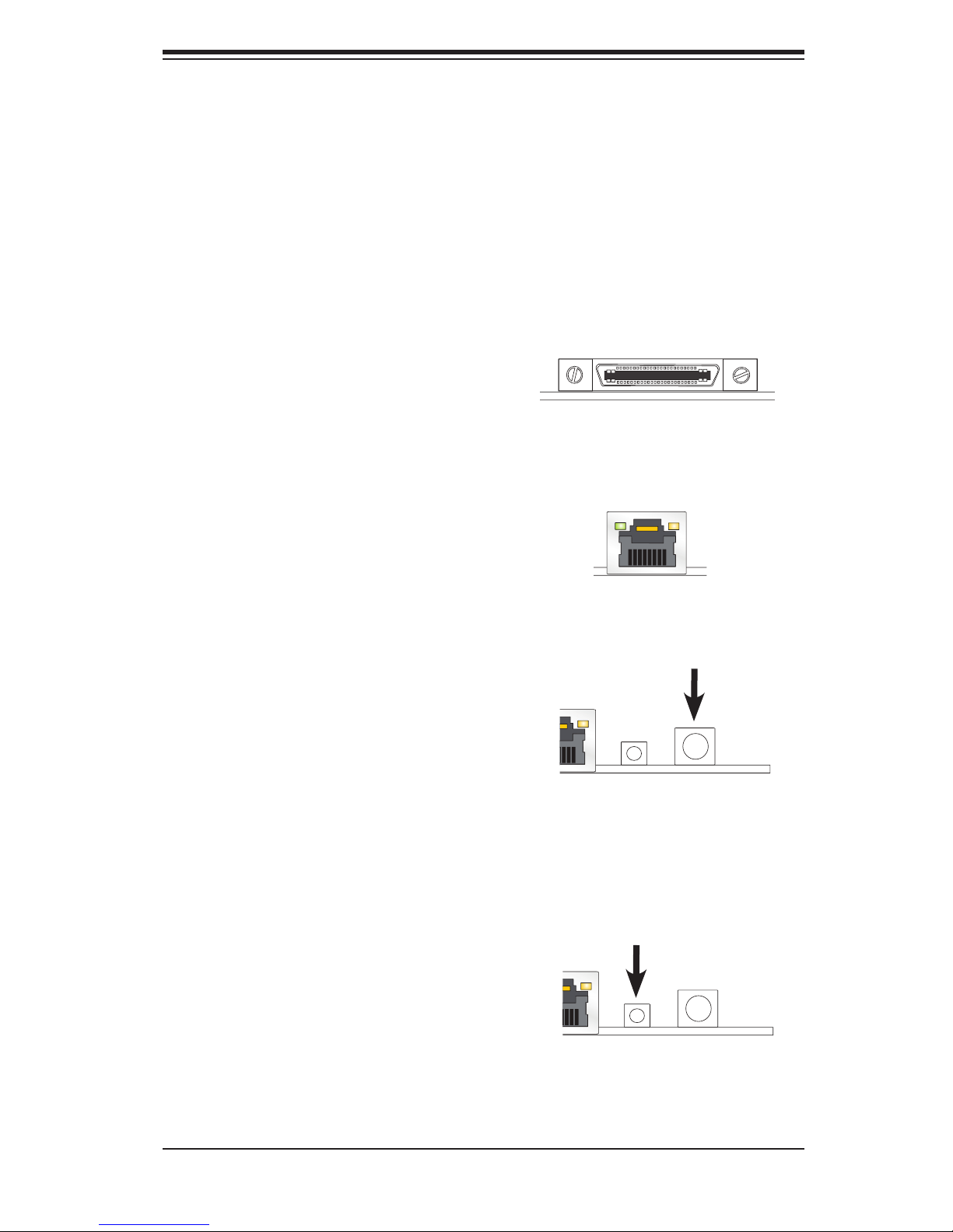
SATA DOM Power (JWF1)
The SATA DOM Power on JWF1 is used
to supply power to SATA Disk-on-Module
(DOM) solid-state storage devices.
5-10 I/O Port Defi nitions
KVM Port
The KVM port supports two USB devices
and VGA and UART interfaces. Please
attach a compatible KVM connector/
switch to this port.
Chapter 5: Advanced Motherboard Setup
IPMI Port
A dedicated IPMI LAN port is located
next to the KVM port to provide dedi-
cated network connection for IPMI 2.0.
This port accepts RJ45 type cables.
Power Button & LED
A Power Button and LED is located right
next to the IPMI port. Push this button
to turn on the motherboard. When lit, it
indicates that this particular motherboard
is turned on.
UID Button
The Unit ID (UID) Button is used in
conjunction with the UID switch in front
of the chassis and the UID LED located
next to it. When the switch is turned
on, the UID LED will turn on, making
pinpointing of the node from the front
or back panel easier, when servicing is
required for instance. See UID LED on
Chapter 2.
5-13
Page 48
SUPERSERVER 5037MC-H8TRF User's Manual
5-11 Jumper Settings
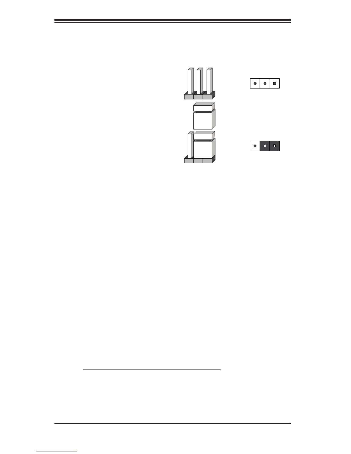
Explanation of Jumpers
To modify the operation of the mother-
board, jumpers can be used to choose
between optional settings. Jumpers
create shorts between two pins to
change the function of the connector.
Pin 1 is identifi ed with a square solder
pad on the printed circuit board. See
the motherboard layout pages for
jumper locations.
Note: On a two-pin jumper, "Closed"
means the jumper is on both pins and
"Open" means the jumper is either on
only one pin or completely removed.
3 2 1
Connector
Pins
Jumper
3 2 1
Setting
CMOS Clear
JBT1 is used to clear CMOS (which will also clear any passwords). Instead of pins,
this jumper consists of contact pads to prevent accidentally clearing the contents
of CMOS.
To clear CMOS,
1. First power down the system and unplug the power cord(s). It is also recom-
mended that you remove the onboard battery from the motherboard.
2. With the power disconnected, short the CMOS pads with a metal object such
as a small screwdriver.
3. Remove the screwdriver (or shorting device).
4. Reconnect the power cord(s) and onboard battery and power on the system.
Note: Do not use the PW_ON connector to clear CMOS.
5-14
Page 49

Chapter 5: Advanced Motherboard Setup
VGA Enable (JPG1)
JPG1 allows the user to enable the
onboard VGA connector (through the
KVM). Close pins 1~2 to enable the
VGA. The default setting is Enabled.
Watch Dog RST/NMI Selection
(JWD1)
Watch Dog (JWD1) is a system moni-
tor that can reboot the system when a
software application hangs. Close pins
1~2 to reset the system if an applica-
tion hangs. Close pins 2~3 to generate
a non-maskable interrupt signal for
the application that hangs. See the
table on the right for jumper settings.
Watch Dog must also be enabled in
the BIOS.
VGA Enable/Disable
Jumper Settings
Jumper Setting Defi nition
Pins 1-2 Enabled
Pins 2-3 Disabled
Watch Dog
Jumper Settings
Jumper Setting Defi nition
Pins 1-2 Reset
Pins 2-3 NMI
Open Disabled
SMB (I
2
C) Bus to PCI Slots (JI2C1/
JI2C2)
Jumpers JI
2
C1 and JI2C2 allow you to
connect the System Management Bus
(SMB) to the PCI-E slots. The default
setting is set to Disabled. See the
table on the right for jumper settings.
BMC Enable/Disable (JPB1)
Jumper JPB1 allows you to enable the
embedded BMC (Baseboard Manage-
ment Controller) to provide IPMI 2.O/
KVM support on the motherboard.
See the table on the right for jumper
settings..
I2C to PCI-Slots
Jumper Settings
Jumper Defi nition
On Enabled
Off Disabled (Default)
BMC Enable
Jumper Settings
Pin# Defi nition
1-2 Enabled (default)
2-3 Disabled
5-15
Page 50
SUPERSERVER 5037MC-H8TRF User's Manual
5-12 Onboard Indicators
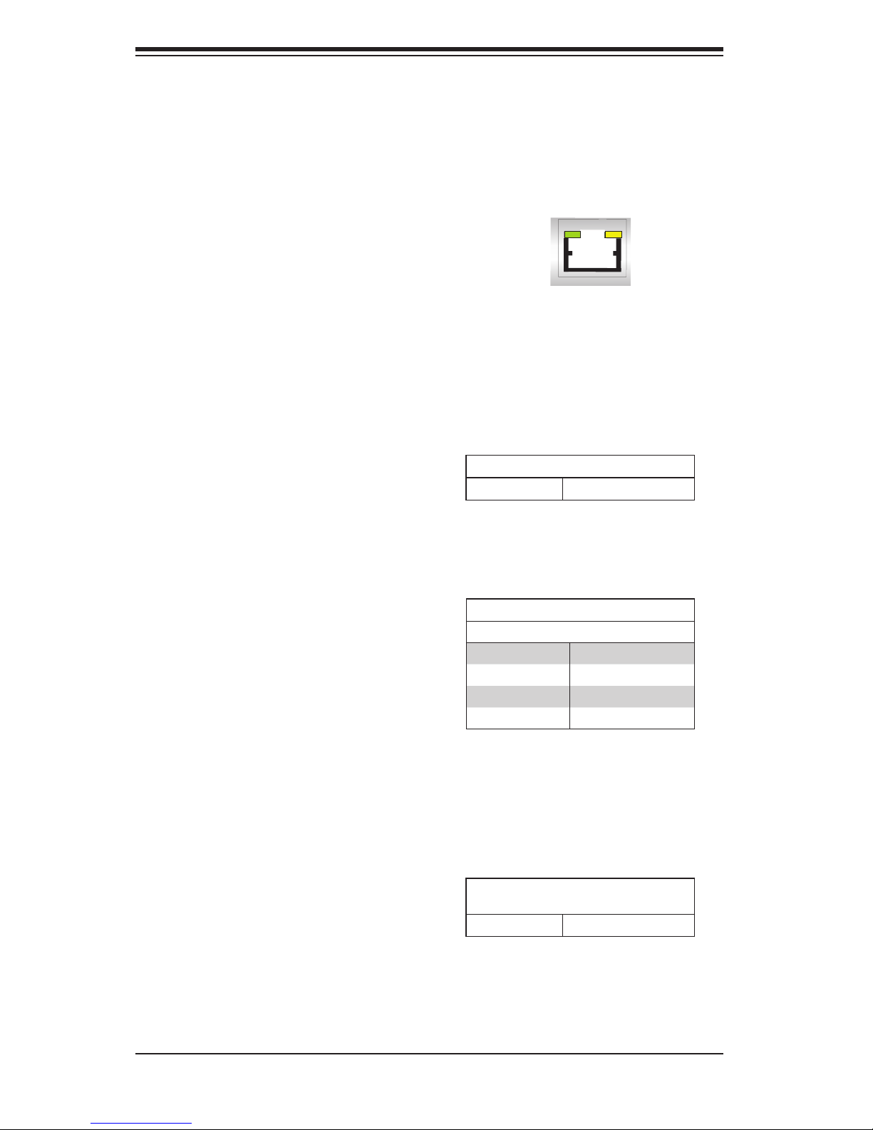
IPMI Dedicated LAN Port
An IPMI Dedicated LAN port installed
on the I/O back panel. The yellow LED
on the right indicates activity, while
the green LED on the left indicates
the speed of the connection. See the
tables at right for more information.
IPMI Heartbeat LED
An IPMI Heartbeat LED is located at
LED4. When LED4 blinks, the IPMI
functions properly. Refer to the table
on the right for details. Also see the
layout below for the LED location.
System Fail LED
LED5 indicates a system failure when
illuminated. Please see the table on
the right for message descriptions.
Activity LEDLink LED
IPMI
IPMI Heartbeat LED Indicator
Blinking IPMI is ready for use
System Fail LED Indicator
LED Color Defi nition
Off System Normal
Red (On - Solid) System Overheat
Red (Blinking) Fan Failure
Red (Blinking) Power Failure
Unit ID LED
The Unit LED is controlled by the
Unit ID Button. It enables the user to
pinpoint this particular motherboard
that may be in need of service. Turn
on the UID button in the front of the
chassis or on the motherboard's I/O
panel to identify the unit in need of
servicing.
Unit ID LED
LED Settings
On (Steady) Unit ID switch is on
5-16
Page 51
Chapter 5: Advanced Motherboard Setup
5-13 SATA Drive Connections
The SATA drive connections are made automatically when a drive is inserted into
its bay in the chassis. No cables are needed to make the power and data con-
nections.
5-14 Installing Software
After the hardware has been installed, you should fi rst install the operating system
and then the drivers. The necessary drivers are all included on the Supermicro CDs
that came packaged with your motherboard.
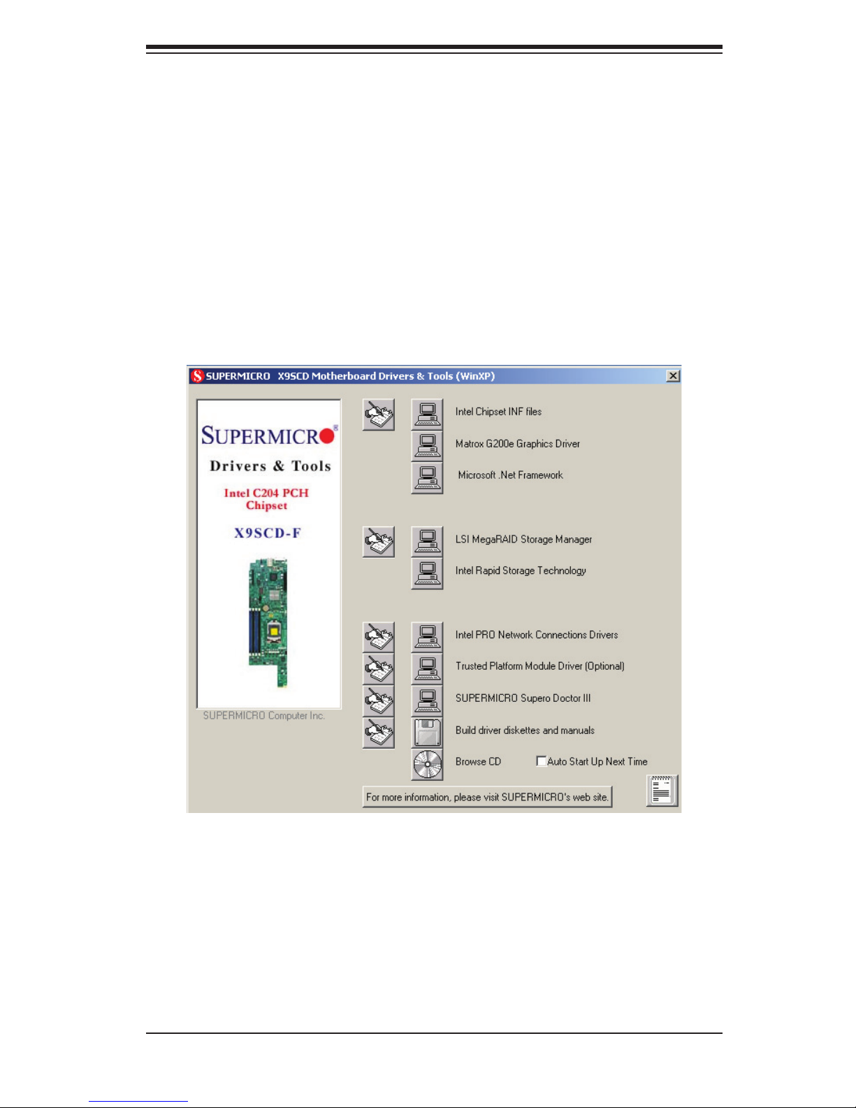
Note: Click the icons showing a hand writing on paper to view the readme fi les
for each item. Click the computer icons to the right of these items to install each
item (from top to the bottom) one at a time. After installing each item, you must
re-boot the system before moving on to the next item on the list. The bottom
icon with a CD on it allows you to view the entire contents of the CD.
Driver/Tool Installation Display Screen
5-17
Page 52
SUPERSERVER 5037MC-H8TRF User's Manual
Supero Doctor III
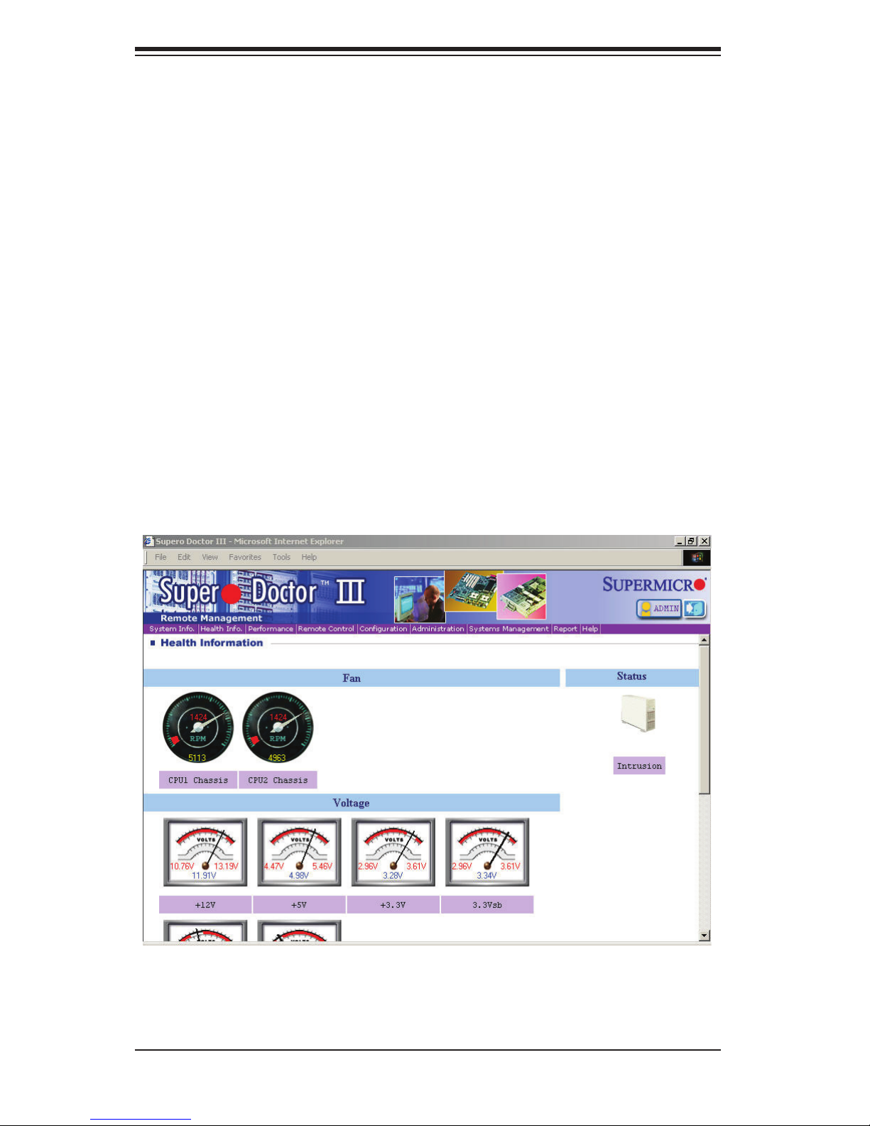
The Supero Doctor III program is a Web base management tool that supports remote
management capability. It includes Remote and Local Management tools. The local
management is called SD III Client. The Supero Doctor III program included on the
CD-ROM that came with your motherboard allows you to monitor the environment
and operations of your system. Supero Doctor III displays crucial system information
such as CPU temperature, system voltages and fan status. See the Figure below
for a display of the Supero Doctor III interface.
Note: The default User Name and Password for SuperDoctor III is ADMIN / AD-
MIN.
Note: When SuperDoctor III is fi rst installed, it adopts the temperature threshold
settings that have been set in BIOS. Any subsequent changes to these thresholds
must be made within Super Doctor, as the Super Doctor settings override the BIOS
settings. To set the BIOS temperature threshold settings again, you would fi rst need
to uninstall SuperDoctor III.
Supero Doctor III Interface Display Screen (Health Information)
5-18
Page 53
Chapter 5: Advanced Motherboard Setup
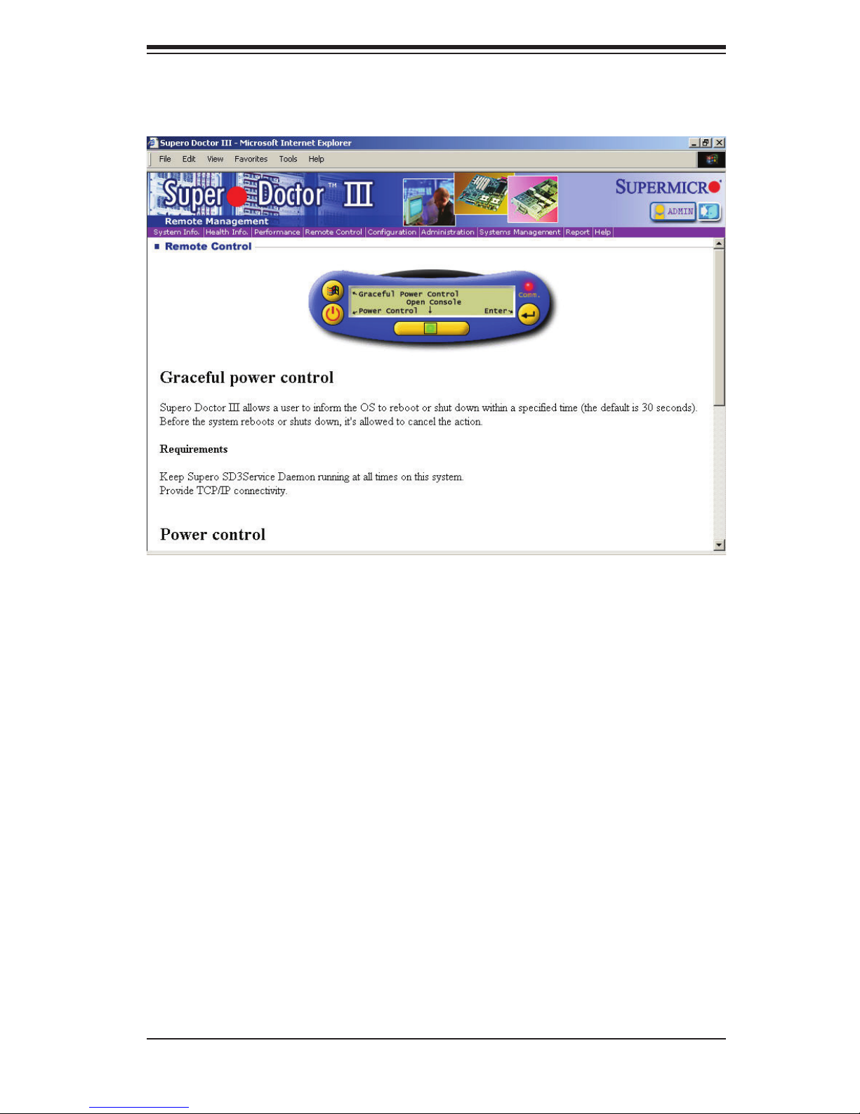
Supero Doctor III Interface Display Screen (Remote Control)
Note: SD III Software Revision 1.0 can be downloaded from our Web Site at: ftp://ftp.
supermicro.com/utility/Supero_Doctor_III/. You can also download the SDIII User's
Guide at: <http://www.supermicro.com/PRODUCT/Manuals/SDIII/UserGuide.pdf>.
For Linux, we will recommend using Supero Doctor II.
5-19
Page 54

SUPERSERVER 5037MC-H8TRF User's Manual
Notes
5-20
Page 55

Chapter 6: Advanced Chassis Setup
Chapter 6
Advanced Chassis Setup
This chapter covers the steps required to install components and perform mainte-
nance on the SC938H-R1620B chassis. For component installation, follow the steps
in the order given to eliminate the most common problems encountered. If some
steps are unnecessary, skip ahead to the step that follows.
Tools Required: The only tool you will need to install components and perform
maintenance is a Philips screwdriver.
6-1 Static-Sensitive Devices
Electrostatic Discharge (ESD) can damage electronic com ponents. To prevent
damage to any printed circuit boards (PCBs), it is important to handle them very
carefully. The following measures are generally suffi cient to protect your equipment
from ESD damage.
Precautions
• Use a grounded wrist strap designed to prevent static discharge.
• Touch a grounded metal object before removing any board from its antistatic
bag.
• Handle a board by its edges only; do not touch its components, peripheral chips,
memory modules or gold contacts.
• When handling chips or modules, avoid touching their pins.
• Put the motherboard, add-on cards and peripherals back into their antistatic
bags when not in use.
• For grounding purposes, make sure your computer chassis provides excellent
conductivity between the power supply, the case, the mounting fasteners and
the motherboard.
• The person unpacking the system should be static protected.
6-1
Page 56
SUPERSERVER 5037MC-H8TRF User's Manual
!
6-2 Removing the Chassis Cover
Remove Film
From Vents
4
1
Remove Three
2
1
Screws
3
1
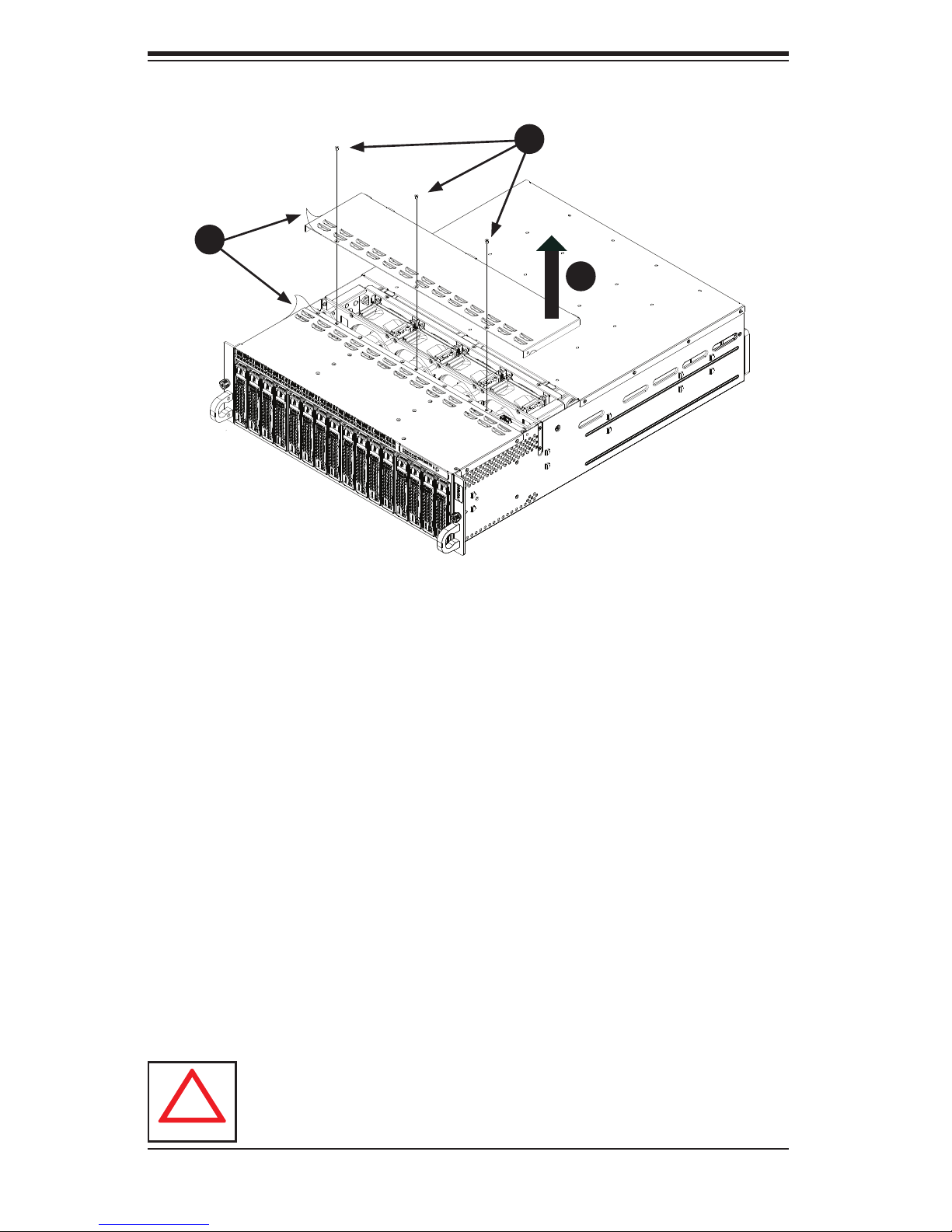
Figure 6-1. Removing the Chassis Cover
IMPORTANT: Before operating the SC938H for the fi rst time, it is important to re-
move the protective fi lm covering the ventilation openings on the top of the chassis.
These vents provide proper ventilation and cooling for the system.
Removing the Chassis Cover and Protective Film
1. Disconnect the chassis from any power source.
2. Remove the three screws which secure the top cover to the chassis as il-
lustrated above.
3. Lift the top cover up and off the chassis.
4. Peel off the protective fi lm covering the top cover and the top of the chassis
5. Check that all ventilation openings on the top cover and the top of the chassis
are clear and unobstructed.
Warning: Except for short periods of time, do NOT operate the server
without the cover in place. The chassis cover must be in place to allow
proper airfl ow and prevent overheating.
6-2
Page 57
Chapter 6: Advanced Chassis Setup
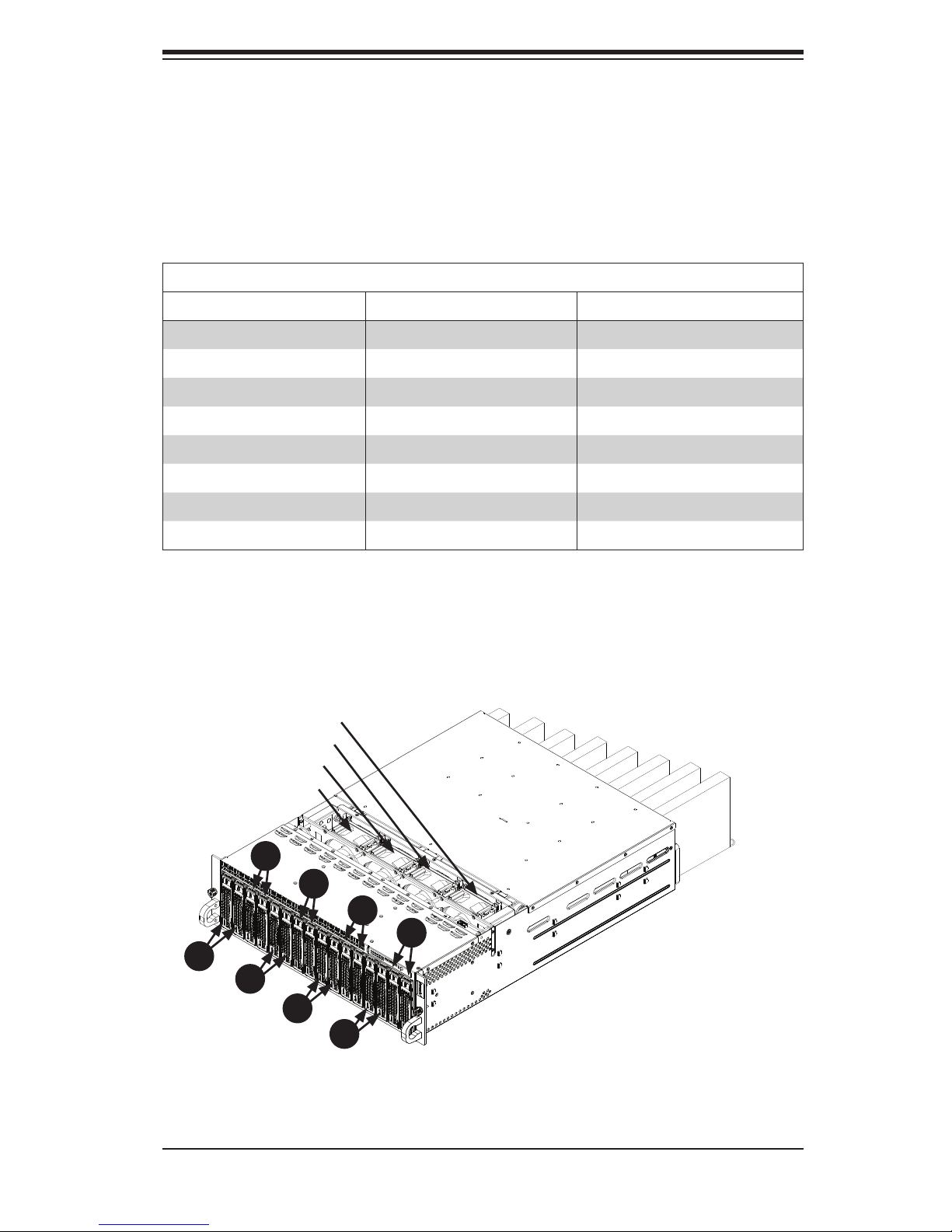
6-3 Corresponding Nodes, Fans and Hard Drives
The SC938H chassis contains eight individual motherboards contained in separate
nodes. Each node controls two hard drives and shares a fan with the node beside
it. Note that if a node is pulled out of the chassis, the hard drives associated with
that node will power-down.
Corresponding Nodes, Fans and HDDs
Node Fan HDDs
Node 1 Fan 1 HDDs A1 and A2
Node 2 Fan 1 HDDs B1 and B2
Node 3 Fan 2 HDDs C1 and C2
Node 4 Fan 2 HDDs D1 and D2
Node 5 Fan 3 HDDs E1 and E2
Node 6 Fan 3 HDDs F1 and F2
Node 7 Fan 4 HDDs G1 and G2
Node 8 Fan 4 HDDs H1 and H2
Figure 6-2. Corresponding Nodes, Fans and HDDs
Node 1
Node 2
Node 3
Node 4
Node 5
A
1
C
1
Fan 2
Fan 1
B
1
Fan 4
Fan 3
D
1
F
1
H
1
Node 6
Node 7
Node 8
E
1
G
1
6-3
Page 58
SUPERSERVER 5037MC-H8TRF User's Manual
6-4 Removing and Installing Hard Drives
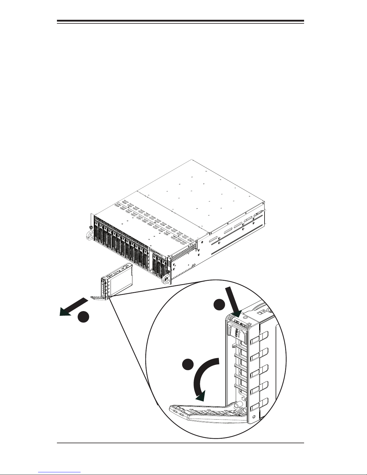
The SC938H features sixteen hot-swappable hard drives. These hard drives are
contained in drive carriers and may be removed without powering-down the system.
Removing Hard Drive Carriers from the Chassis
1. Press the release button on the drive carrier, which will extend the drive car-
rier handle.
2. Use the drive carrier handle to pull the drive out of the chassis.
Figure 6-3. Removing a Hard Drive
3
1
6-4
1
1
2
1
Page 59
Chapter 6: Advanced Chassis Setup
!
Dummy Drive
2
1
Drive Carrier
2
1
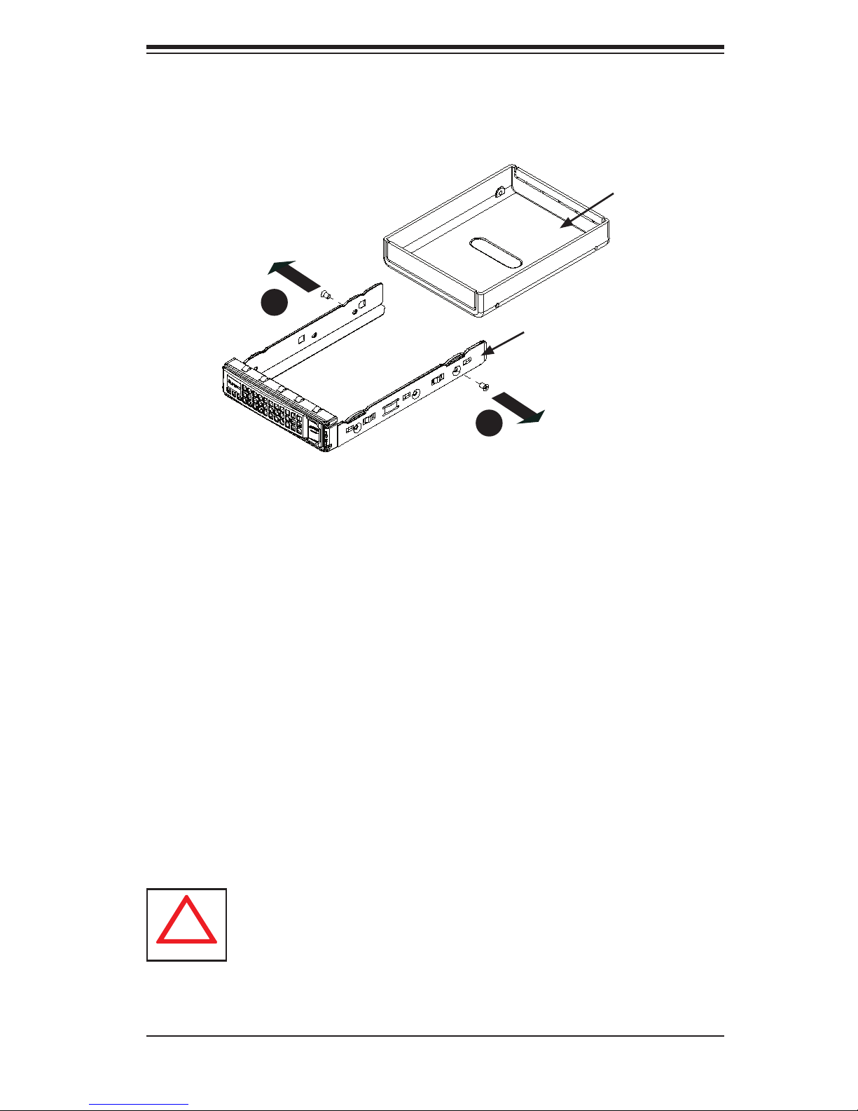
Figure 6-4. Removing a Dummy Drive from the Drive Carrier
The hard drives are mounted in drive carriers to simplify their installation and re-
moval from the chassis. These carriers also help promote proper airfl ow through
the drive bays.
Removing the Dummy Drive from the Drive Carrier
1. Remove the hard drive carrier from the chassis as described in the previous
section and lay the drive carrier on a fl at surface.
2. Remove the two screws securing the dummy drive to the drive carrier.
3. Lift the dummy drive from the drive carrier.
Warning: Except for short periods of time while swapping hard drives, do
not operate the server with the hard drive bays empty. All carriers (even
without hard drives present) must remain in their bays to maintain proper
airfl ow.
6-5
Page 60
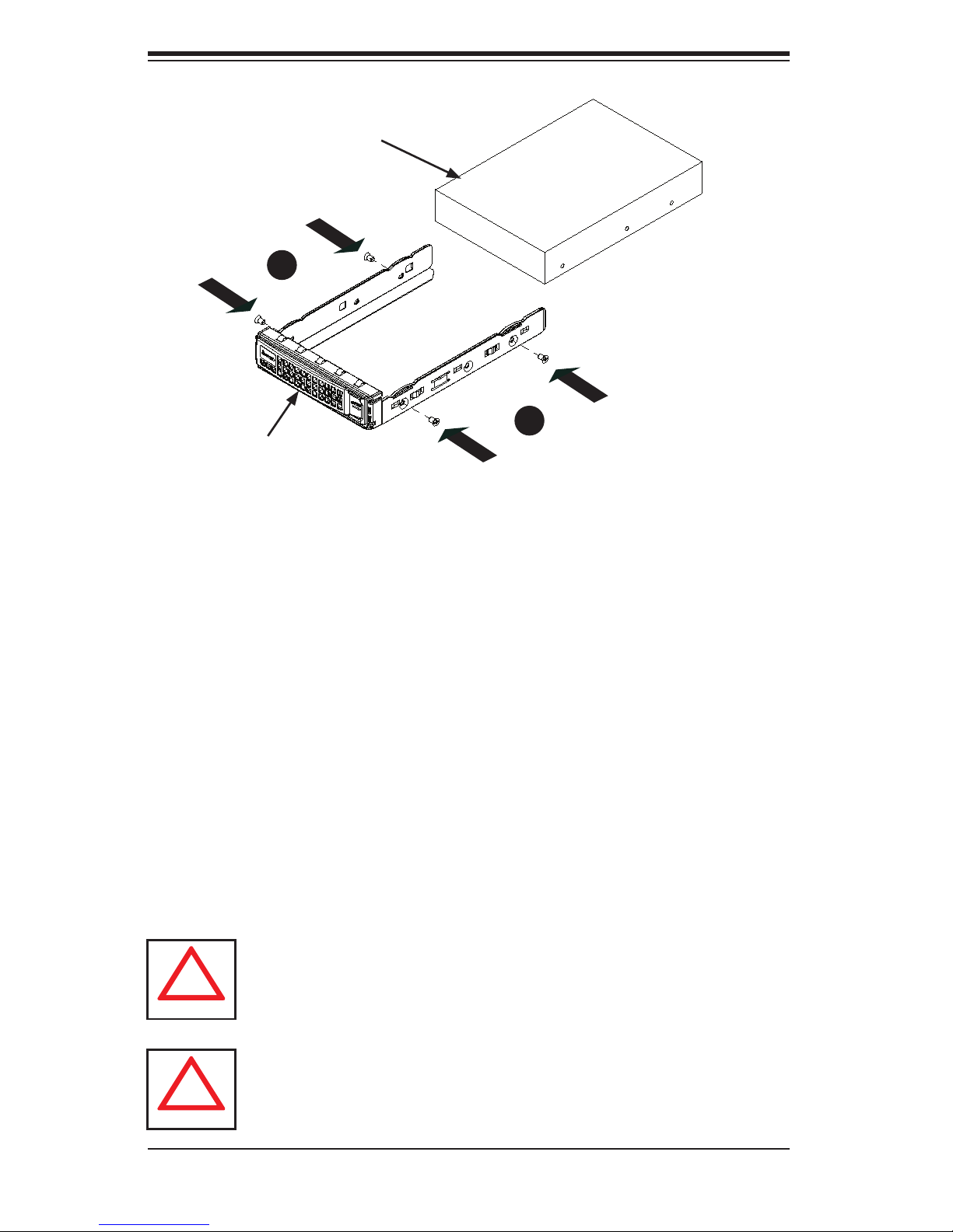
SUPERSERVER 5037MC-H8TRF User's Manual
!
!
Hard Drive
4
1
Drive Carrier
4
1
Figure 6-5. Installing a Hard Drive
Installing a Hard Drive into the Drive Carrier
1. Place the hard drive carrier on a fl at surface.
2. Insert the hard drive into the carrier with the printed circuit board side facing
downward and so that the mounting holes in the drive align with those in the
drive carrier.
3. Secure the hard drive to the carrier with the four screws included with the
hard drive.
4. Use the open handle of the drive carrier to insert the drive carrier into the
open drive bay.
5. Secure the drive carrier into the drive bay by closing the drive carrier handle.
Regardless of how many hard drives are installed, all drive carriers must
remain in the drive bays to promote proper airfl ow.
Enterprise level hard disk drives are recommended for use in Supermicro
chassis and servers. For information on recommended HDDs, visit the
Supermicro Web site at http://www.supermicro.com/products/nfo/storage.
cfm
6-6
Page 61
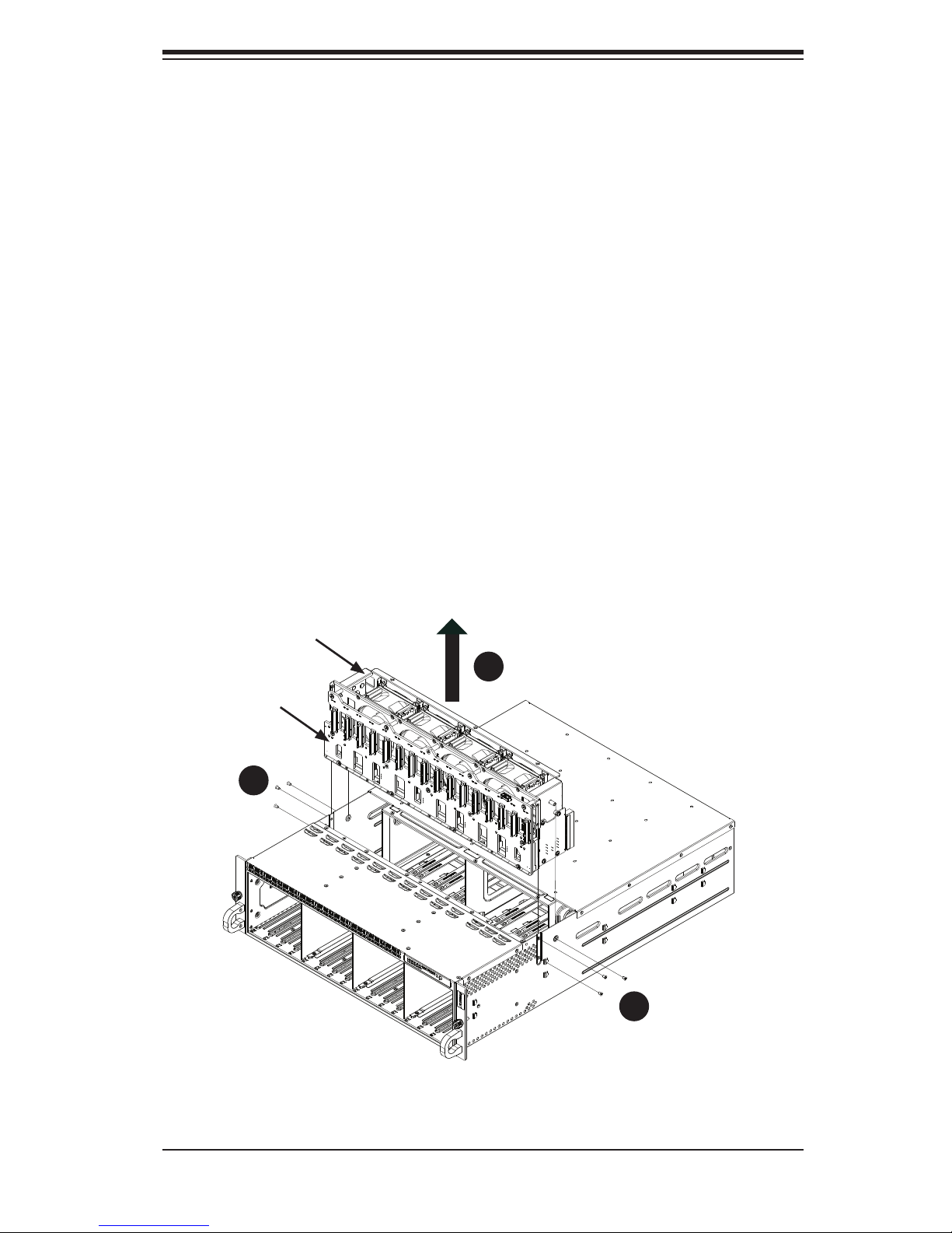
Chapter 6: Advanced Chassis Setup
6-5 Removing and Installing the Backplane
The backplane is attached to the fan bracket, which is located in the midsection
of the chassis. In the unlikely event of a backplane failure, follow the instructions
below to replace it.
Removing the Backplane and Fan Bracket Assembly
Removing the Backplane and Fan Bracket from the Chassis
1. Power down the system and disconnect it from any power source.
2. Remove the chassis cover as described in section 6-2 of this manual.
3. Disconnect all cabling to the backplane.
4. Remove the six screws securing the fan bracket to the chassis and set them
aside for later use.
5. Lift the fan bracket and backplane out of the chassis.
Fan Bracket
5
1
Backplane
4
1
Figure 6-6. Removing the Fan Bracket and Backplane
6-7
4
1
Page 62
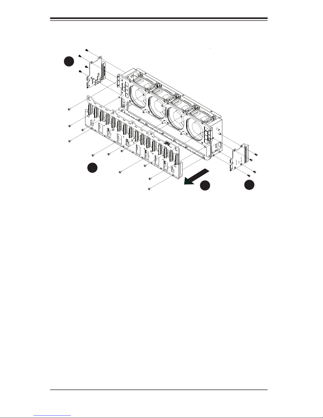
SUPERSERVER 5037MC-H8TRF User's Manual
1
1
2
1
3
1
Figure 6-7. Removing the Backplane from the Fan Bracket
1
1
Removing the Backplane from the Fan Bracket
Removing the Backplane
1. Remove the eight screws securing the two side mounting brackets to the
sides of the fan bracket and set them aside for later use. Remove the side
mounting brackets.
2. Remove the eleven screws securing the backplane to the fan bracket and set
these screws aside for later use.
3. Hold the backplane by its edges and carefully remove it from the fan bracket.
6-8
Page 63
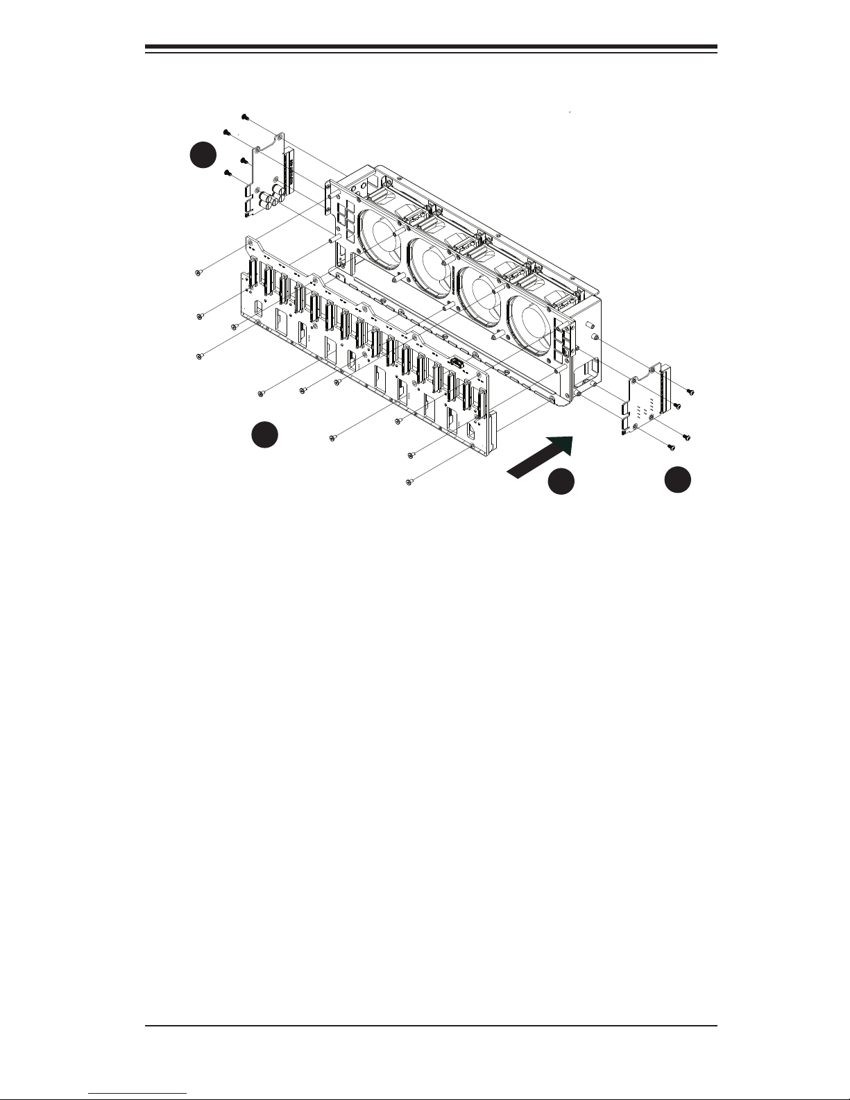
Chapter 6: Advanced Chassis Setup
3
1
4
1
2
1
Figure 6-8. Installing the Backplane onto the Fan Bracket
3
1
Installing the Backplane onto the Fan Bracket
Installing the Backplane
1. Ensure that all power has been disconnected from the chassis.
2. Hold the backplane by its edges and carefully place it against the fan mount-
ing bracket, aligning the mounting holes in the backplane with those in the fan
bracket.
3. Secure the two side mounting brackets to the backplane with the eight screws
previously set aside.
4. Secure the backplane to the front of the fan bracket using the eleven screws
previously set aside.
5. Reconnect all wiring to the backplane.
6-9
Page 64
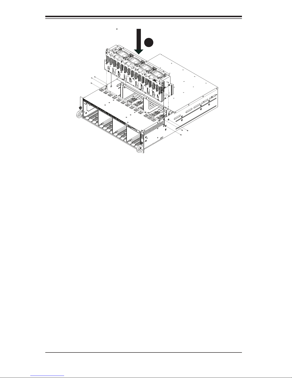
SUPERSERVER 5037MC-H8TRF User's Manual
4
1
Figure 6-9. Installing the Backplane and Fan Bracket
Installing the Backplane and Fan Bracket Assembly
Installing the Backplane and Fan Bracket
1. Ensure that the chassis has been disconnected from any power source.
2. Remove the chassis cover as described in Section 6-2.
3. Reconnect the wiring to the backplane.
4. Insert the fan bracket and backplane assembly into the chassis as illustrated
above.
5. Secure the fan bracket to the chassis with the six screws that were previously
set aside.
6-10
Page 65
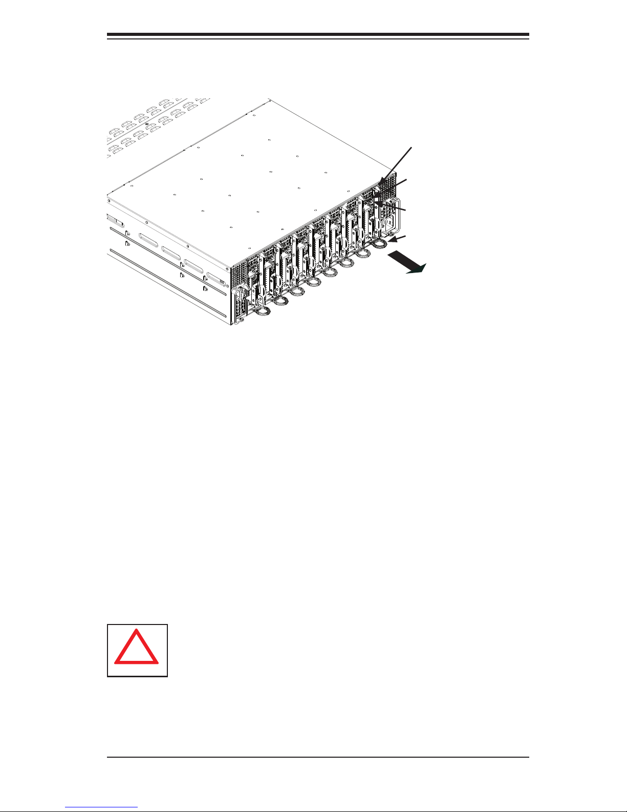
Chapter 6: Advanced Chassis Setup
!
6-6 Removing and Installing Motherboard Nodes
Release Tab
Node Power LED
Node Power Button
Node Handle
Figure 6-10. Removing Nodes from the System
The SC938H chassis comes equipped with eight removable nodes, each one con-
taining an individual motherboard. Removing these nodes will also power-down the
corresponding hard drives. See the table in Section 6-3 to determine which hard
drives are controlled by each node.
Removing Nodes from the System
1. Power-down the individual node by pressing that node's power button.
2. Press and hold down the release tab on the back of the node.
3. Using the node's handle, pull the node from the chassis.
Warning: Except for short periods of time while swapping nodes, do not
operate the server with the node bays empty. In the unlikely event of a
node failure, remove the failed node and replace it with the dummy node
that was included with the system..
6-11
Page 66

SUPERSERVER 5037MC-H8TRF User's Manual
6-7 Installing an Air Shroud
Air shrouds concentrate airfl ow to maximize fan effi ciency. The SC938H chassis
requires that air shrouds be used in each node.
Installing the Air Shroud
1. Make sure that the motherboard expansion card (if present) and all compo-
nents are properly installed in each motherboard node.
2. Place the air shroud over the motherboard, as shown below. The air shroud
sits behind the system fans and goes over the top of the motherboard and its
components. Secure by inserting screws through the tabs and tightening.
3. Repeat the procedure for the remaining nodes.
4. Reverse this procedure to remove an air shroud.
6-12
Page 67

Chapter 6: Advanced Chassis Setup
6-8 System Fans
Four 8-cm fans circulate air through the chassis to lower the internal temperature.
The SC938H system fans are designed to be easily changed, with no tools required
and no need to remove any other parts inside the chassis. See Section 6-3 to de-
termine which nodes and hard drives are cooled by each system fan.
Replacing a System Fan
1. If necessary, open the chassis top cover while the system is operating to
determine which fan has failed. Never run the server for an extended period
of time with the top cover open.
2. Remove the failed fan's power cord from the backplane.
3. Simultaneously squeeze both release tabs on the top of the fan module.
4. Lift the fan module up and out of the chassis.
5. Place the replacement fan into the vacant space in the fan bracket while mak-
ing sure the arrows on the top of the fan (indicating air direction) point in the
same direction as the arrows on the other fans.
6. Put the fan back into the chassis and reconnect the cable.
7. Confi rm that the fan is working properly before replacing the chassis cover.
6-13
Page 68
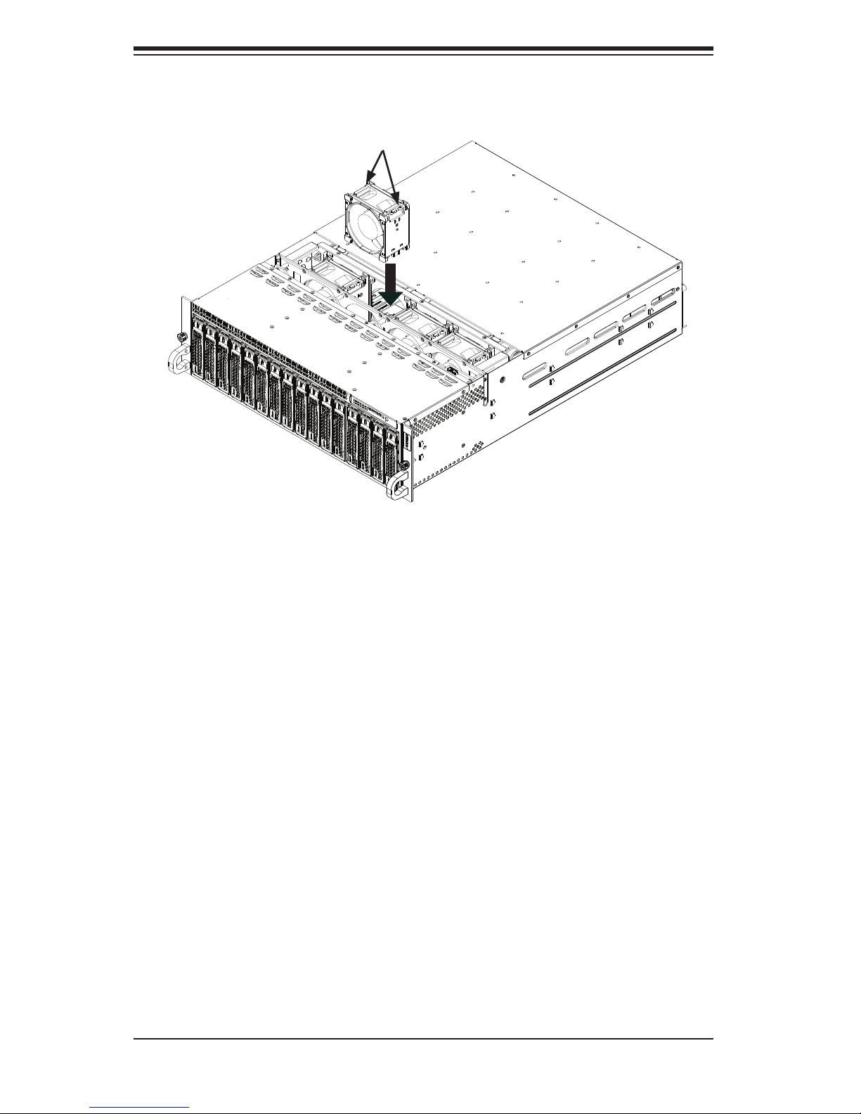
SUPERSERVER 5037MC-H8TRF User's Manual
Figure 6-13. System Fan Placement
Release Tabs
6-9 Power Supply
The SC938H chassis includes a redundant 1620 watt power supply, which is auto-
switching capable. This enables it to automatically sense and operate at a 100V to
240V input voltage. An amber light will be illuminated on the power supply when the
power is off. An illuminated green light indicates that the power supply is operating.
Power Supply Replacement
In the unlikely event that one of the power supplies needs to be replaced, one power
supply can be removed without powering-down the system. Replacement power
supply units may be ordered directly from Supermicro See the contact information
in the Preface of this manual or visit www.supermicro.com.
6-14
Page 69
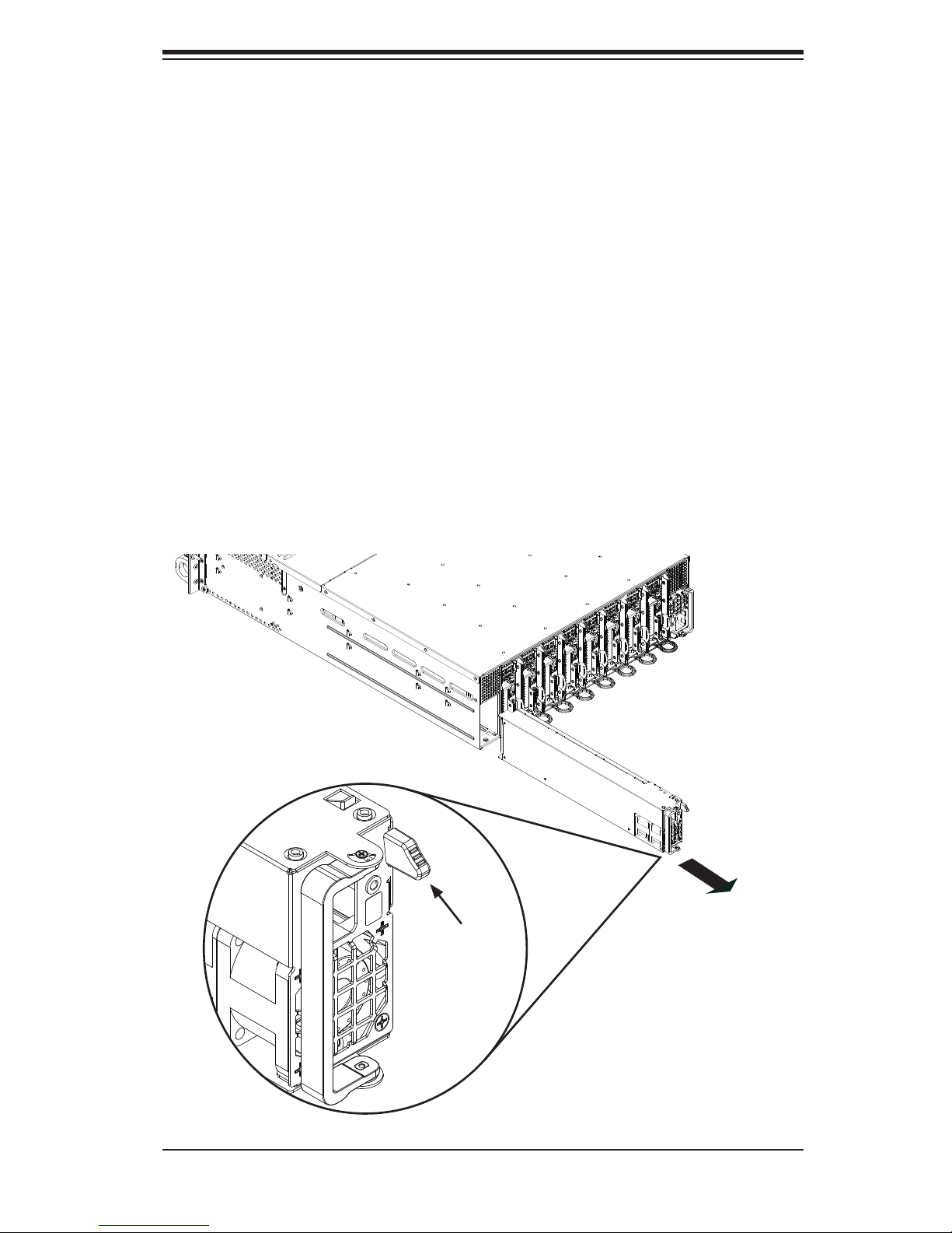
Chapter 6: Advanced Chassis Setup
Changing the Power Supply
1. Unplug the AC power cord from the failed power supply.
2. With the system running, press the release tab at the top of the power supply
3. Push and hold the release tab on the back of the power supply.
4. Pull the power supply out using the handle provided.
5. Push the replacement power supply module into the chassis' power bay until
it clicks into the locked position.
6. Plug the AC power cord back into the power supply module and power- up
the nodes if needed (with a single power supply failure, the nodes should
continue to run).
Figure 6-14. Changing the Power Supply
Release Tab
6-15
Page 70

SUPERSERVER 5037MC-H8TRF User's Manual
Notes
6-16
Page 71
Chapter 7: AMI BIOS
Chapter 7
BIOS
7-1 Introduction
This chapter describes the AMI BIOS Setup Utility for the X9SCD-F motherboard.
The AMI ROM BIOS is stored in a Flash EEPROM and can be easily updated.
This chapter describes the basic navigation of the AMI BIOS Setup Utility setup
screens.
Note: For instructions on BIOS recovery, please refer to the instruction
guide posted at http://www.supermicro.com/support/manuals/.
Starting BIOS Setup Utility
To enter the AMI BIOS Setup Utility screens, press the <Delete> key while the
system is booting up.
Note: In most cases, the <Delete> key is used to invoke the AMI BIOS
setup screen. There are a few cases when other keys are used, such as
<F1>, <F2>, etc.
Each main BIOS menu option is described in this manual. The Main BIOS setup
menu screen has two main frames. The left frame displays all the options that can
be confi gured. Grayed-out options cannot be confi gured. Options in blue can be
confi gured by the user. The right frame displays the key legend. Above the key
legend is an area reserved for a text message. When an option is selected in the
left frame, it is highlighted in white. Often a text message will accompany it. (Note:
the AMI BIOS has default text messages built in. Supermicro retains the option to
include, omit, or change any of these text messages.)
The AMI BIOS Setup Utility uses a key-based navigation system called "hot keys".
Most of the AMI BIOS setup utility "hot keys" can be used at any time during the
setup navigation process. These keys include <F1>, <F10>, <Enter>, <ESC>, ar-
row keys, etc.
Note: Options printed in Bold are default settings.
How To Change the Confi guration Data
The confi guration data that determines the system parameters may be changed by
entering the AMI BIOS Setup utility. This Setup utility can be accessed by pressing
<Del> at the appropriate time during system boot.
7-1
Page 72
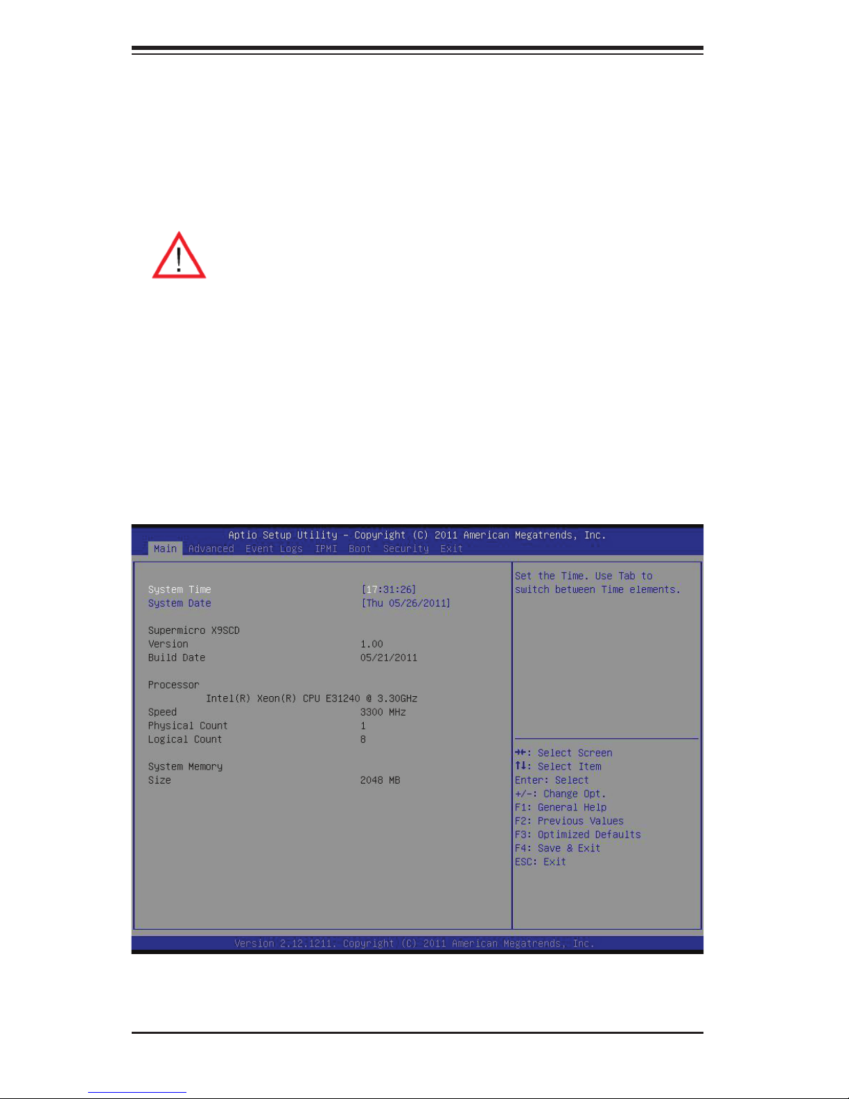
SUPERSERVER 5037MC-H8TRF User's Manual
How to Start the Setup Utility
Normally, the only visible Power-On Self-Test (POST) routine is the memory test.
As the memory is being tested, press the <Delete> key to enter the main menu of
the AMI BIOS Setup Utility. From the main menu, you can access the other setup
screens. An AMI BIOS identifi cation string is displayed at the left bottom corner of
the screen, below the copyright message.
Warning! Do not upgrade the BIOS unless your system has a BIOS-related
issue. Flashing the wrong BIOS can cause irreparable damage to the
system. In no event shall Supermicro be liable for direct, indirect, special,
incidental, or consequential damages arising from a BIOS update. If you
have to update the BIOS, do not shut down or reset the system while the
BIOS is updating. This is to avoid possible boot failure.
7-2 Main Setup
When you fi rst enter the AMI BIOS Setup Utility, you will enter the Main setup screen.
You can always return to the Main setup screen by selecting the Main tab on the
top of the screen. The Main BIOS Setup screen is shown below.
7-2
Page 73

Chapter 7: AMI BIOS
System Overview: The following BIOS information will be displayed:
System Time/System Date
Use this option to change the system time and date. Highlight System Time or Sys-
tem Date using the arrow keys. Enter new values through the keyboard. Press the
<Tab> key or the arrow keys to move between fi elds. The date must be entered in
Day MM/DD/YY format. The time is entered in HH:MM:SS format. (Note: The time
is in the 24-hour format. For example, 5:30 P.M. appears as 17:30:00.)
Supermicro X9SCD
Version
Build Date
Processor
The AMI BIOS will automatically display the status of processor as shown below:
Processor
Speed
Physical Count
Logical Count
System Memory
This displays the size of memory available in the system:
Size
7-3
Page 74
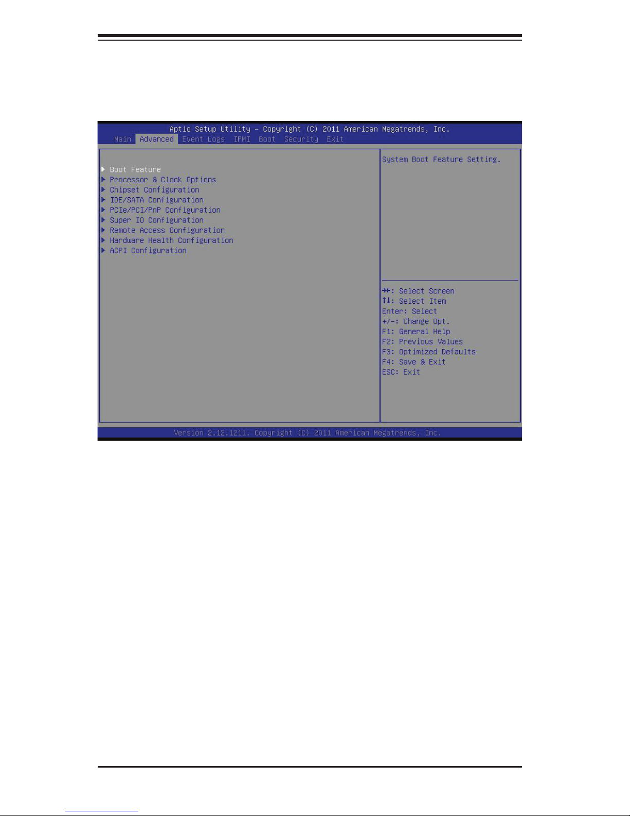
SUPERSERVER 5037MC-H8TRF User's Manual
7-3 Advanced Setup Confi gurations
Use the arrow keys to select Boot Setup and hit <Enter> to access the submenu
items:
X
BOOT Feature
Quiet Boot
This feature allows the user to select the bootup screen display between POST
messages and the OEM logo. Select Disabled to display the POST messages.
Select Enabled to display the OEM logo instead of the normal POST messages.
The options are Enabled and Disabled.
AddOn ROM Display Mode
This feature sets the display mode for Option ROM. The options are Force BIOS
and Keep Current.
Bootup Num-Lock
This feature selects the Power-on state for Numlock key. The options are Off
and On.
7-4
Page 75
Chapter 7: AMI BIOS
Wait For 'F1' If Error
Select Enabled to force the system to wait until the 'F1' key is pressed if an error
occurs. The options are Disabled and Enabled.
Interrupt 19 Capture
Interrupt 19 is the software interrupt that handles the boot disk function. When this
item is set to Enabled, the ROM BIOS of the host adaptors will "capture" Interrupt
19 at boot and allow the drives that are attached to these host adaptors to function
as bootable disks. If this item is set to Disabled, the ROM BIOS of the host adap-
tors will not capture Interrupt 19, and the drives attached to these adaptors will not
function as bootable devices. The options are Enabled and Disabled.
Watch Dog Function
If enabled, the Watch Dog Timer will allow the system to reboot when it is inactive
for more than 5 minutes. The options are Enabled and Disabled.
Power Button Function
This feature controls how the system shuts down when the power button is pressed.
Select 4-Second Override to force the user to press and hold the Power Button for
4 seconds before the system turns off. Select Instant Off if you want the system to
instanty power off when the Power Button is pressed. The options are 4 Second
Override and Instant Off.
Restore on AC Power Loss
Use this feature to set the power state after a power outage. Select Power-Off for
the system power to remain off after a power loss. Select Power-On for the system
power to be turned on after a power loss. Select Last State to allow the system to
resume its last state before a power loss. The options are Power-On, Power-Off
and Last State.
X
Processor & Clock Options
Warning: Take Caution when changing the Advanced settings. An incorrect
value, a very high DRAM frequency or incorrect DRAM timing may cause
system to become unstable. When this occurs, revert to the default setting.
Clock Spread Spectrum
Select Enabled to allow BIOS to monitor and attempt to reduce the level of Elec-
tromagnetic Interference caused by the components whenever needed. Select
Disabled to enhance system stability. The options are Disabled and Enabled.
7-5
Page 76

SUPERSERVER 5037MC-H8TRF User's Manual
Hardware Prefetcher (Available when supported by the CPU)
If set to Enabled, the hardware prefetcher will prefetch streams of data and instruc-
tions from the main memory to the L2 cache in the forward or backward manner to
improve CPU performance. The options are Disabled and Enabled.
Adjacent Cache Line Prefetch (Available when supported by the CPU)
The CPU fetches the cache line for 64 bytes if this option is set to Disabled. The
CPU fetches both cache lines for 128 bytes as comprised if Enabled.
Intel® Virtualization Technology (Available when supported by the CPU)
Select Enabled to use the feature of Virtualization Technology to allow one platform
to run multiple operating systems and applications in independent partitions, creat-
ing multiple "virtual" systems in one physical computer. The options are Enabled
and Disabled. Note: If there is any change to this setting, you will need to power
off and restart the system for the change to take effect. Please refer to Intel’s web
site for detailed information.
Execute-Disable Bit Capability (Available when supported by the OS and
the CPU)
Set to Enabled to enable the Execute Disable Bit which will allow the processor
to designate areas in the system memory where an application code can execute
and where it cannot, thus preventing a worm or a virus from fl ooding illegal codes
to overwhelm the processor or damage the system during an attack. The default is
Enabled. (Refer to Intel and Microsoft Web Sites for more information.)
Intel® Hyper Threading Technology
Set to Enabled to use the processor's Hyper Threading Technology feature. The
options are Enabled and Disabled.
Active Processor Cores
Set to Enabled to use a processor's Second Core and beyond. (Please refer to
Intel's web site for more information.) The options are All, 1, 2 and 3.
Power Technology
This feature determines what power-saving scheme the motherboard uses. The
options are Disabled, Energy Effi cient and Custom. If Custom is selected, the
following options become available:
EIST
EIST (Enhanced Intel SpeedStep Technology) allows the system to automati-
cally adjust processor voltage and core frequency in an effort to reduce
7-6
Page 77

Chapter 7: AMI BIOS
power consumption and heat dissipation. Please refer to Intel’s web site
for detailed information. The options are Disabled and Enabled.
P-STATE Coordination
This feature selects the type of coordination for the P-State of the processor.
P-State is a processor operational state that reduces the processor's voltage
and frequency. This makes the processor more energy effi icient, resulting in
further gains. The options are HW_ALL, SW_ALL and SW-ANY.
CPU C3 Report, CPU C6 Report
This BIOS feature enables or disables C3 (ACPI C2) or C6 (ACPI C3) report-
ing to the operating system. The options are Disabled and Enabled.
Package C-State Limit
If set to Auto, the AMI BIOS will automatically set the limit on the C-State package
register. The options are C0, C1, C6, C7 and No Limit.
X
Turbo Boost Technology (Available if Intel® EIST
technology is Enabled)
Turbo Mode
This feature allows processor cores to run faster than marked frequency in
specifi c conditions. The options are Disabled and Enabled.
Long duration power limit - this is the processor power consumption limit
(in Watts) during a long duration time window.
Long duration maintained - this is the time in milliseconds where the Long
Duration Power Limit is maintained.
Short duration power limit - During Turbo Mode, the system may exceed
the processor's default power setting and exceed the Short Duration Power
limit. By increasing this value, the processor can provide better performance
for a short duration.
X
Chipset Confi guration
WARNING: Setting the wrong values in the following sections may cause the
system to malfunction.
X
CPU Bridge Confi guration
This item displays the current CPU Revision, Current CPU1 Memory Fre-
quency, Memory Type and Memory Reference Code Revision.
7-7
Page 78

SUPERSERVER 5037MC-H8TRF User's Manual
Memory Frequency
This feature allows the user to select the memory speed. Under normal
conditions, please set this to Auto. The options are Auto, Force DDR-800,
Force DDR-1067, Force DDR-1333, and Force DDR-1600.
X
Integrated I/O Confi guration
This item displays the current North Bridge Revision.
VT-d
Select Enabled to enable Intel's Virtualization Technology support for
Direct I/O VT-d
the DMAR ACPI Tables. This feature offers fully-protected I/O resource-
sharing across the Intel platforms, providing the user with greater reliabil-
ity, security and availability in networking and data-sharing. The settings
are Enabled and Disabled.
by reporting the I/O device assignments to VMM through
Active State Power Management
Select Enabled to start Active-State Power Management for signal
transactions between L0 and L1 Links on the PCI Express Bus. This
maximizes power-saving and transaction speed. The options are Enabled
and Disabled.
PCIE Maximum Payload Size
This feature selects the setting for the PCIE maximum payload size. The
options are Auto, 128 Bytes, 256 Bytes, 512 Bytes, 1024 Bytes, 2048
Bytes, and 4096 Bytes.
PCI Express Port
This feature enables or disables the PCI Express port. The options are
Disabled, Enabled and Auto.
PEG Force Gen1
This feature forces Gen1 support on the PCI Express Graphics (PEG)
port. The options are Disabled, and Enabled.
Detect Non-Compliant Device
This feature enables or disables the detection of a non-compliant device
that is attached to the PCI Express Graphics (PEG) port. The options are
Disabled, and Enabled.
7-8
Page 79

Chapter 7: AMI BIOS
X
South Bridge Confi guration
This item displays the current South Bridge Revision.
USB Functions
This feature allows the user to decide the number of onboard USB ports to
be enabled. The Options are Disabled and Enabled.
Legacy USB Support (available if USB Functions above is Enabled)
Select Enabled to use Legacy USB devices. If this item is set to Auto, Legacy
USB support will be automatically enabled if a legacy USB device is installed
on the motherboard, and vise versa. The settings are Disabled, Enabled and
Auto.
Port 60/64 Emulation (available if USB Functions above is Enabled)
Select Enabled to activate I/O port 60h/64h emulation support. This must be
enabled for complete USB keyboard legacy support for Operating Systems
that are not compatible with USB devices. The settings are Enabled and
Disabled.
BIOS EHCI Hand-Off (available if USB Functions above is Enabled)
This item is for Operating Systems that does not support Enhanced Host
Controller Interface (EHCI) hand-off. When enabled, EHCI ownership change
will be claimed by the EHCI driver. The settings are Enabled and Disabled.
X
IDE/SATA Confi guration
When this submenu is selected, the AMI BIOS automatically detects the presence
of the IDE devices and displays the following items:
SATA Mode
This item selects the mode for the installed drives. The options are Disabled, IDE
Mode, AHCI Mode and RAID Mode.
IDE Mode
The following items are displayed when IDE Mode is selected:
Serial-ATA Controller 0~1
This feature is used to activate/deactivate the SATA controller, and sets
the compatibility mode. The options are Enhanced and Compatible. The
default of Serial-ATA Controller 1 is Enhanced.
7-9
Page 80

SUPERSERVER 5037MC-H8TRF User's Manual
SATA Port0~Port5
This item displays the information detected on the installed SATA drives
on the particular SATA port.
AHCI Mode
The following items are displayed when AHCI Mode is selected:
Aggressive Link Power Management
This feature Enables or Disables Agressive Link Power Management
support for Cougar Point B0 stepping and later. The options are Enabled
and Disabled.
SATA Port0~Port5
This item displays the information detected on the installed SATA drives
on the particular SATA port.
Staggered Spin Up
Set this item to Enabled for Staggered Spin-up support. The options
are Enabled and Disabled.
Hot Plug
Set this item to Enabled for hot-plugging support. The options are
Enabled and Disabled.
RAID Mode
The following items are displayed when RAID Mode is selected:
PCH RAID CodeBase
Select Intel to enable the Intel SATA Host RAID Utility. Select LSI to use
the LSI Host RAID Utility. The options are Intel and LSI.
SATA Port0~Port5
This item displays the information detected on the installed SATA drives
on the particular SATA port.
Hot Plug
Set this item to Enabled to enable hot-plugging. The options are
Enabled and Disabled.
7-10
Page 81

Chapter 7: AMI BIOS
X
PCIe/PCI/PnP Confi guration
This feature allows the user to set the PCI/PnP confi gurations for the following
items:
PCI ROM Priority
In case of multiple Option ROMs (Legacy and EFI-compatible), this feature specifi es
what ROM to launch. The options are Legacy ROM and EFI Compatible ROM.
PCI Latency Timer
This feature sets the latency Timer of each PCI device installed on a PCI bus. Select
64 to set the PCI latency to 64 PCI clock cycles. The options are 32, 64, 96, 128,
160, 192, 224 and 248.
X
Super IO Device Confi guration
Serial Port 1
Select Enabled to enable the onboard serial port. The options are Enabled and
Disabled.
Serial Port 1 Settings
This option specifi es the base I/O port address and the Interrupt Request address
of Serial Port 1. Select Auto to allow the serial port to automatically assign system
resources. The options for Serial Port 1 are Auto, (IO=3F8h; IRQ=4), (IO=3F8h;
IRQ=3, 4, 5, 6, 7, 10, 11, 12), (IO=2F8h; IRQ=3, 4, 5, 6, 7, 10, 11, 12),. (IO=3E8h;
IRQ=3, 4, 5, 6, 7, 10, 11, 12), (IO=2E8h; IRQ=3, 4, 5, 6, 7, 10, 11, 12),
X
Remote Access Confi guration
COM1 Console Redirection
Use this feature to enable console redirection for the COM1 port. The options are
Enabled and Disabled. The default for all ports are Disabled.
X
Console Redirection Settings
Confi gure the following options for the Console Redirection Settings. The
most common settings are set as default:
Terminal Type : Select ANSI, VT100, VT100+, or VT-UTF8
Bits per Second (BPS): 9600, 19200, 57600, or 115200
Data Bits: 8 or 7
7-11
Page 82

SUPERSERVER 5037MC-H8TRF User's Manual
Parity: None, Even, Odd, Mark, or Space
Stop Bits: 1 or 2
Flow Control: None or Hardware RTS/CTS
Recorder Mode: Disabled or Enabled
Resolution 100x31: Disabled or Enabled
Legacy OS Redirection Resolution: 80x24 or 80x25
SOL Console Redirection
Use this feature to enable console redirection for SOL (Serial Over LAN). The options
are Enabled and Disabled. The default for all ports are Disabled.
X
Console Redirection Settings
Confi gure the following options for the Console Redirection Settings. The
most common settings are set as default:
Terminal Type : Select ANSI, VT100, VT100+, or VT-UTF8
Bits per Second (BPS): 9600, 19200, 57600, or 115200
Data Bits: 8 or 7
Parity: None, Even, Odd, Mark, or Space
Stop Bits: 1 or 2
Flow Control: None or Hardware RTS/CTS
Recorder Mode: Disabled or Enabled
Resolution 100x31: Disabled or Enabled
Legacy OS Redirection Resolution: 80x24 or 80x25
Serial Port for Out-of-Band Management / Windows Emergency
Management Services (EMS)
Use this feature to enable console redirection. The options are Enabled and Dis-
abled. The default is Disabled.
X
Console Redirection Settings
Confi gure the following options for the Console Redirection Settings. The
most common settings are set as default:
Out-of-Band Mgmt Port: COM1, SOL
Terminal Type : Select ANSI, VT100, VT100+, or VT-UTF8
Bits per Second (BPS): 9600, 19200, 57600, or 115200
7-12
Page 83

Chapter 7: AMI BIOS
Data Bits: 8 or 7
Parity: None, Even, Odd, Mark, or Space
Stop Bits: 1 or 2
X
Hardware Health Confi guration
Fan Speed Control Mode
This feature allows the user to decide how the system controls the speeds of the
onboard fans. The CPU temperature and the fan speed are correlative. When the
CPU on-die temperature increases, the fan speed will also increase for effective
system cooling. Select "Full Speed" to allow the onboard fans to run at full speed
(of 100% Pulse Width Modulation Duty Cycle) for maximum cooling. This setting
is recommended for special system confi guration or debugging. Select "Standard"
for the onboard fans to run at 50% of the Initial PWM Cycle in order to balance the
needs between system cooling and power saving. This setting is recommended
for regular systems with normal hardware confi gurations. Select "Optimal" for the
onboard fans to run at 30% of the Initial PWM Cycle for best power effi ciency and
maximum quietness. The options are Full Speed (@100% of PWM Cycle), Standard
(@50% of PWM Cycle), and Optimal (@30% of PWM Cycle).
CPU Temperature, System Temperature
This feature displays the current temperature of the above monitors.
Fan1 Speed
This feature displays the fan speed reading from the Fan 1 interface.
VCORE, 12V, VDIMM, 5VCC, VCC PCH, AVCC, 3.3VCC, VSB, VBAT
This feature displays the current voltages of the above voltage monitors.
X
ACPI Confi guration
Use this feature to confi gure Advanced Confi guration and Power Interface (ACPI)
power management settings for your system.
High Precision Event Timers
Select Enabled to activate the High Performance Event Timer (HPET) that produces
periodic interrupts at a much higher frequency than a Real-time Clock (RTC) does in
synchronizing multimedia streams, providing smooth playback and reducing the de-
pendency on other timestamp calculation devices, such as an x86 RDTSC Instruc-
7-13
Page 84

SUPERSERVER 5037MC-H8TRF User's Manual
tion embedded in the CPU. The High Performance Event Timer is used to replace
the 8254 Programmable Interval Timer. The options are Enabled and Disabled.
Suspend Mode
This setting allows you to confi gure the ACPI (Advanced Confi guration and Power
Interface) sleep state for your system when it is in the Suspend mode. The options
are Suspend Disabled, S1 (POS), and S3 (STR). S3 (STR) is the deepest sleep
state in these options.
WHEA Support
This feature Enables the Windows Hardware Error Architecture (WHEA) support
for the Windows 2008 operating system (and later versions). The options are
Enabled and Disabled.
7-14
Page 85
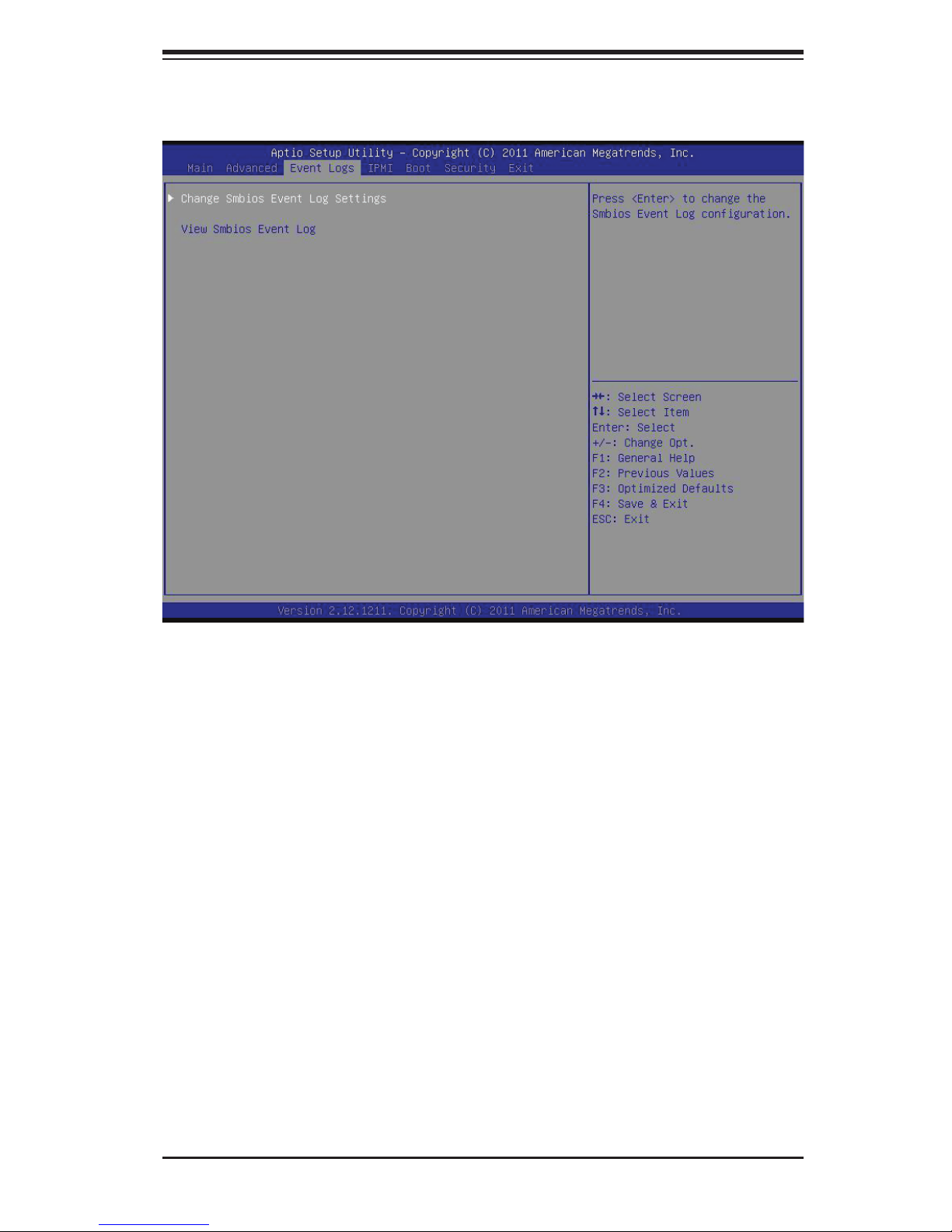
7-4 Event Logs
Chapter 7: AMI BIOS
X
Change Smbios Event Log Settings
The following options are available:
Smbios Event Log
Change this item to enable or disable all features of the Smbios Event Logging
during boot. The options are Enabled and Disabled.
Erase Event Log
This option erases all logged events. The options are No, Yes, Next reset and
Yes, Every reset.
When Log is Full
This option automatically clears the Event Log memory of all messages when
it is full. The options are Do Nothing and Erase Immediately.
MECI
The Multiple Event Count Increment (MECI) counter counts the number of
occurences a duplicate event must happen before the MECI counter is incre-
mented. This is a numeric value.
7-15
Page 86
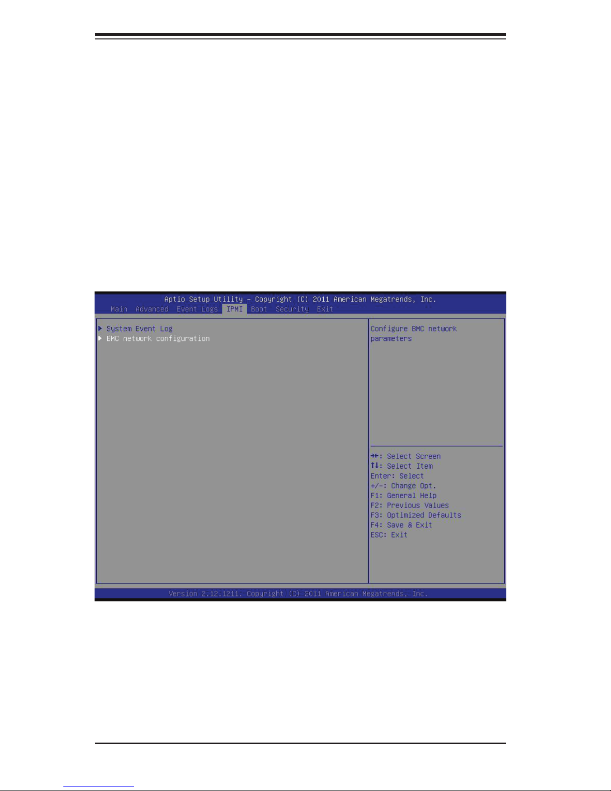
SUPERSERVER 5037MC-H8TRF User's Manual
METW
The Multiple Event Time Window (METW) defi nes number of minutes must pass
between duplicate log events before MECI is incremented. This is in minutes,
from 0 to 99.
View Smbios Event Log
Displays the Smbios Event Log stored in memory.
7-5 IPMI Confi guration
Intelligent Platform Management Interface (IPMI) is a set of common interfaces that
IT administrators can use to monitor system health and to manage the system as a
whole. For more information on the IPMI specifi cations, please visit Intel's website
at www.intel.com.
XSystem Event Log
This feature is used to change the Sytem Event Log (SEL) confi guration.
SEL Components - Change this item to enable or disable all features of System
Event Logging. The options are Enabled and Disabled. When Enabled, the
following can be confi gured:
7-16
Page 87

Chapter 7: AMI BIOS
Erase SEL - This option erases all logged SEL events. The options are No,
Yes, On Next reset and Yes, On Every reset.
When SEL Full
This option automatically clears the System Event Log memory of all messages
when it is full. The options are Do Nothing and Erase Immediately.
XBMC Network Confi guration
Set this feature to confi gure the IPMI LAN adapter with a network address.
Update IPMI LAN Confi guration
Select Yes to update the IPMI LAN confi guration. The options are Yes and No.
Confi guration Source
This feature selects whether the IP address, Subnet Mask and Gateway Address
are automatically assigned by the network's DHCP server (Dynamic Host and Con-
fi guration Protocol) "Dynamic" or manually entered by the user "Static". If Static is
selected, the IP Address, Subnet Mask and Gateway Address must be manually
entered below. The options are Static, Dynamic and Do Nothing. The following
items are displayed when Static is selected:
Station IP Address - Enter the IP address for this machine. This should be in
decimal and in dotted quad form (i.e., 192.168.10.253). The value of each three-
digit number separated by dots should not exceed 255.
Subnet Mask - Subnet masks tell the network which subnet this machine be-
longs to. The value of each three-digit number separated by dots should not
exceed 255.
Station MAC Address - MAC addresses are 6 two-digit hexadecimal numbers
(Base 16, 0 ~ 9, A, B, C, D, E, F) separated by dots (i.e., 00.30.48.D0.D4.60).
Gateway IP Address - Enter the Gateway or Router address this machine will
use (i.e., 192.168.10.1).
7-17
Page 88
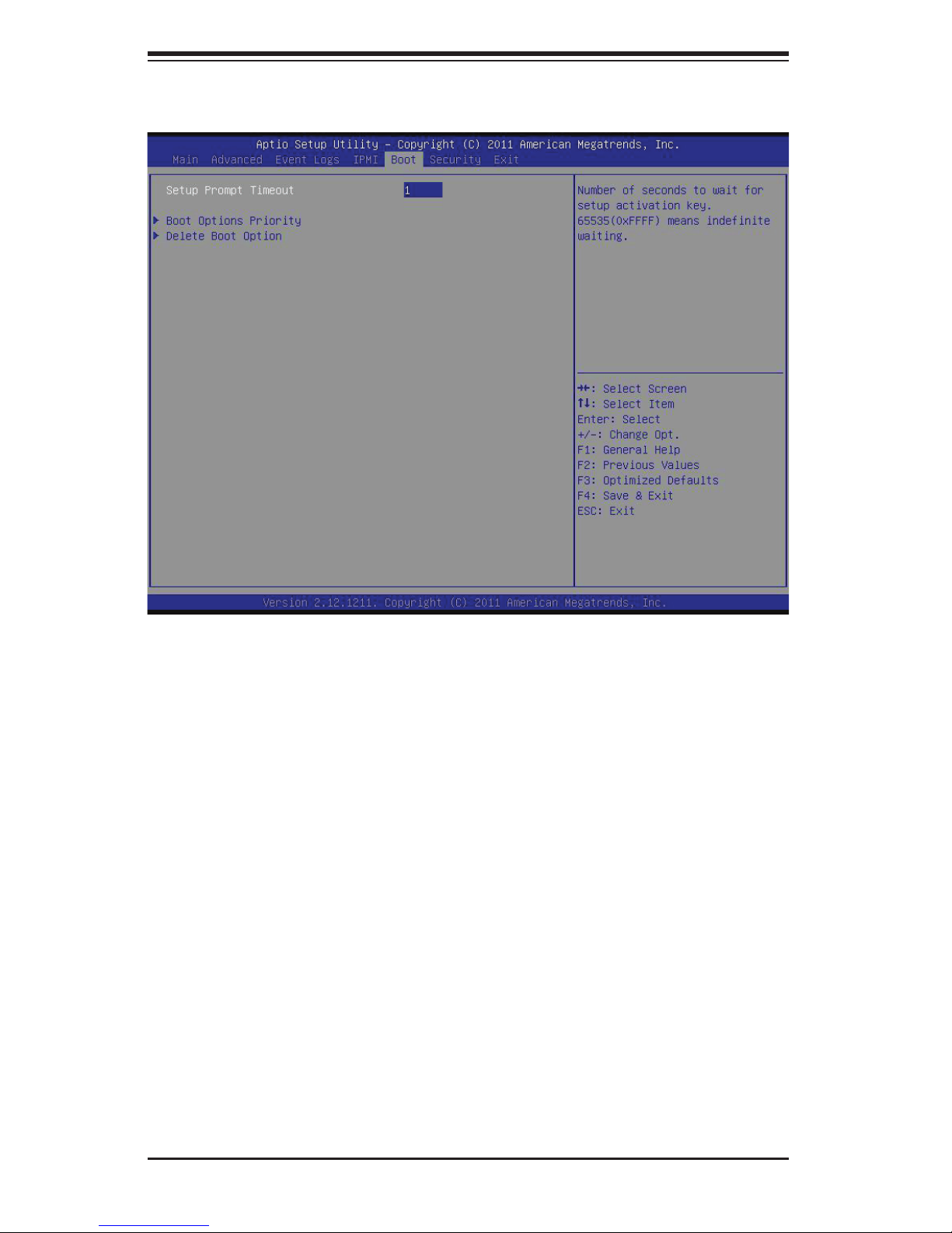
SUPERSERVER 5037MC-H8TRF User's Manual
7-6 Boot Settings
Use this feature to confi gure Boot Settings:
X
Boot Options Priority
This feature allows the user to specify which devices are boot devices and the order
of priority from which the systems boots from during startup.
Boot Option #1, Boot option #2, Boot Option #3, etc
The settings are Built-in EFI Shell, [any detected boot device] and Disabled.
X
Delete Boot Option
This feature allows the user to delete any previously-defi ned boot device from the
Boot Options Priority.
7-18
Page 89
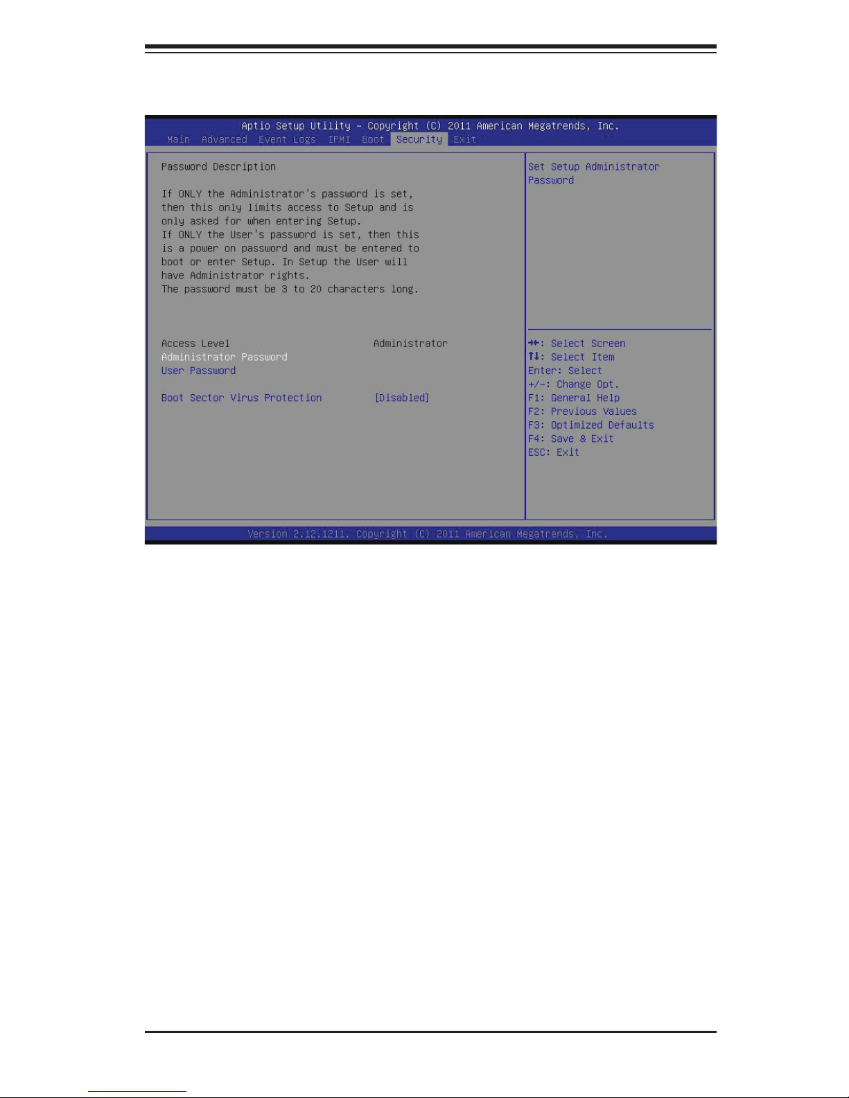
7-7 Security Settings
Chapter 7: AMI BIOS
• If the Administrator password is defi ned ONLY - this controls access to the
BIOS setup ONLY.
• If the User's password is defi ned ONLY - this password will need to be entered
during each system startup or boot, and will also have Administrator rights in
the setup.
• Passwords must be at least 3 and up to 20 characters long.
Administrator Password
Press Enter to create a new, or change an existing Administrator password.
User Password:
Press Enter to create a new, or change an existing User password.
Boot Sector Virus Protection
When this item is Enabled, the BIOS displays a warning when any program (or
virus) issues a Disk Format command or attempts to write to the boot sector of the
hard disk drive. The options are Enabled and Disabled.
7-19
Page 90
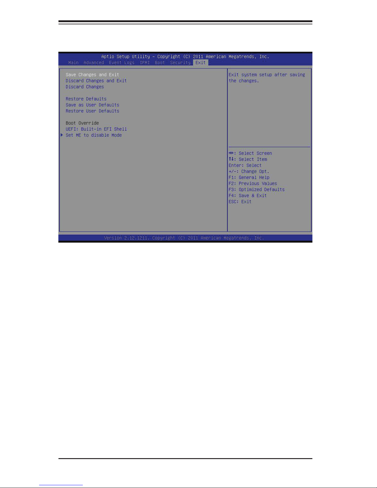
SUPERSERVER 5037MC-H8TRF User's Manual
7-8 Exit Options
Select the Exit tab from the BIOS Setup Utility screen to enter the Exit BIOS Setup
screen.
Save Changes and Exit
When you have completed the system confi guration changes, select this option
to leave the BIOS Setup Utility and reboot the computer, so that the new system
confi guration parameters can take effect. Select Save Changes and Exit from the
Exit menu and press <Enter>.
Discard Changes and Exit
Select this option to quit the BIOS Setup without making any permanent changes
to the system confi guration, and reboot the computer. Select Discard Changes and
Exit from the Exit menu and press <Enter>.
Discard Changes
Select this option and press <Enter> to discard all the changes and return to the
AMI BIOS Utility Program.
7-20
Page 91

Chapter 7: AMI BIOS
Restore Defaults
To set this feature, select Restore Defaults from the Exit menu and press <Enter>.
These are factory settings designed for maximum system stability, but not for
maximum performance.
Save As User Defaults
To set this feature, select Save as User Defaults from the Exit menu and press <En-
ter>. This enables the user to save any changes to the BIOS setup for future use
Restore User Defaults
To set this feature, select Restore User Defaults from the Exit menu and press <En-
ter>. Use this feature to retrieve user-defi ned settings that were saved previously.
Boot Override
Set this feature to override a previously defi ned boot device. The available devices
will be listed below.
7-21
Page 92

SUPERSERVER 5037MC-H8TRF User's Manual
Notes
7-22
Page 93

Appendix A: POST Error Beep Codes
Appendix A
POST Error Beep Codes
This section lists POST (Power On Self Test) error beep codes for the AMI BIOS.
POST error beep codes are divided into two categories: recoverable and terminal.
This section lists Beep Codes for recoverable POST errors.
Recoverable POST Error Beep Codes
When a recoverable type of error occurs during POST, BIOS will display a POST
code that describes the problem. BIOS may also issue one of the following beep
codes:
1 long and two short beeps - video confi guration error
1 repetitive long beep - no memory detected
1 continuous beep with the front panel Overheat LED on - system overheat
8 short beeps - display memory read/write error
A-1
Page 94

SUPERSERVER 5037MC-H8TRF User's Manual
Notes
A-2
Page 95

Appendix B: System Specifi cations
Appendix B
System Specifi cations
Processors
Each node supports one Intel E3-1200 Series processor in an LGA 1155
socket
Note: Please refer to our web site for a complete listing of supported processors.
Chipset
Intel C204 PCH
BIOS
64 Mb AMIBIOS® SM Flash BIOS
Memory Capacity
Each node supports up to 32 GB of ECC DDR3-1333/1066 UDIMM memory
(Total of 256 GB for the system)
Note: See the memory section in Chapter 5 for details.
Drive Bays
Sixteen hot-swap drive bays to house 3.5" SATA drives
Expansion Slots
Each node supports the use of one PCI-E 2.0 x8 low-profi le add-on card (6.6"
maximum length)
Motherboard
X9SCD-F (proprietary form factor)
Dimensions: 4.75" x 15.95" (120.7 x 405 mm)
Chassis
SC938H-R1620B (3U rackmount)
Dimensions: (WxHxD) 17.26 x 5.21 x 23.2 in. (438 x 132 x 589 mm)
Weight
Gross (Bare Bone): 62.2 lbs. (28.3 kg)
B-1
Page 96

SUPERSERVER 5037MC-H8TRF User's Manual
System Cooling
Four 8-cm system fans
System Input Requirements
AC Input Voltage: 100 - 240V AC auto-range
Rated Input Current: 11.5 - 5.5A max
Rated Input Frequency: 50 to 60 Hz
Power Supply
Rated Output Power: 1620W (Part# PWS-1K62P-1R) 80 Plus Bronze Certifi ed
Rated Output Voltages: +12V (84A @ 100-120VAC, 100A @ 120-140VAC,
135A @ 180-264VAC), +5Vsb (4A)
Operating Environment
Operating Temperature: 10º to 35º C (50º to 95º F)
Non-operating Temperature: -40º to 70º C (-40º to 158º F)
Operating Relative Humidity: 20% to 95% (non-condensing)
Non-operating Relative Humidity: 5 to 95% (non-condensing)
Regulatory Compliance
Electromagnetic Emissions:
FCC Class A, EN 55022 Class A, EN 61000-3-2/-3-3, CISPR 22 Class A
Electromagnetic Immunity:
EN 55024/CISPR 24, (EN 61000-4-2, EN 61000-4-3, EN 61000-4-4,
EN 61000-4-5, EN 61000-4-6, EN 61000-4-8, EN 61000-4-11)
Safety:
EN 60950/IEC 60950-Compliant
UL Listed (USA)
CUL Listed (Canada)
TUV Certifi ed (Germany)
CE Marking (Europe)
California Best Management Practices Regulations for Perchlorate Materials:
This Perchlorate warning applies only to products containing CR (Manganese
Dioxide) Lithium coin cells. “Perchlorate Material-special handling may apply.
See www.dtsc.ca.gov/hazardouswaste/perchlorate”
B-2
Page 97

Appendix B: System Specifi cations
B-3
Page 98

SUPERSERVER 5037MC-H8TRF User's Manual
The products sold by Supermicro are not intended for and will not be used in life support systems,
medical equipment, nuclear facilities or systems, aircraft, aircraft devices, aircraft/emergency communication devices or other critical systems whose failure to perform be reasonably expected to
result in signifi cant injury or loss of life or catastrophic property damage. Accordingly, Supermicro dis-
claims any and all liability, and should buyer use or sell such products for use in such ultra-hazardous
applications, it does so entirely at its own risk. Furthermore, buyer agrees to fully indemnify, defend
and hold Supermicro harmless for and against any and all claims, demands, actions, litigation, and
proceedings of any kind arising out of or related to such ultra-hazardous use or sale.
(continued from front)
B-4
 Loading...