

Supero SuperServer 5036I-I, SuperServer 5036I-IF User Manual
SUPER
SuperServer 5036I-I/5036I-IF
®
USER’S MANUAL
Revision 1.0

The information in this User’s Manual has been carefully reviewed and is believed to be accurate.
The vendor assumes no responsibility for any inaccuracies that may be contained in this document,
makes no commitment to update or to keep current the information in this manual, or to notify any
person or organization of the updates. Please Note: For the most up-to-date version of this
manual, please see our web site at www.supermicro.com.
Super Micro Computer, Inc. ("Supermicro") reserves the right to make changes to the product
described in this manual at any time and without notice. This product, including software, if any,
and documentation may not, in whole or in part, be copied, photocopied, reproduced, translated or
reduced to any medium or machine without prior written consent.
IN NO EVENT WILL SUPERMICRO BE LIABLE FOR DIRECT, INDIRECT, SPECIAL, INCIDENTAL,
SPECULATIVE OR CONSEQUENTIAL DAMAGES ARISING FROM THE USE OR INABILITY TO
USE THIS PRODUCT OR DOCUMENTATION, EVEN IF ADVISED OF THE POSSIBILITY OF
SUCH DAMAGES. IN PARTICULAR, SUPERMICRO SHALL NOT HAVE LIABILITY FOR ANY
HARDWARE, SOFTW ARE, OR DA TA STORED OR USED WITH THE PRODUCT, INCLUDING THE
COSTS OF REPAIRING, REPLACING, INTEGRATING, INSTALLING OR RECOVERING SUCH
HARDWARE, SOFTWARE, OR DATA.
Any disputes arising between manufacturer and customer shall be governed by the laws of Santa
Clara County in the State of California, USA. The State of California, County of Santa Clara shall
be the exclusive venue for the resolution of any such disputes. Super Micro's total liability for
all claims will not exceed the price paid for the hardware product.
This equipment has been tested and found to comply with the limits for a Class B digital device
pursuant to Part 15 of the FCC Rules. These limits are designed to provide reasonable protection
against harmful interference in a residential installation. This equipment generates, uses, and can
radiate radio frequency energy and, if not installed and used in accordance with the manufacturer’s
instruction manual, may cause interference with radio communications. However, there is no
guarantee that interference will not occur in a particular installation. If this equipment does cause
harmful interference to radio or television reception, which can be determined by turning the
equipment off and on, you are encouraged to try to correct the interference by one or more of the
following measures: Reorient or relocate the receiving antenna. Increase the separation between
the equipment and the receiver. Connect the equipment into an outlet on a circuit different from
that to which the receiver is connected. Consult the dealer or an experienced radio/television
technician for help.
California Best Management Practices Regulations for Perchlorate Materials: This Perchlorate
warning applies only to products containing CR (Manganese Dioxide) Lithium coin cells. “Perchlorate
Material-special handling may apply. See www.dtsc.ca.gov/hazardouswaste/perchlorate”
WARNING: Handling of lead solder materials used in this
product may expose you to lead, a chemical known to
the State of California to cause birth defects and other
reproductive harm.
Manual Revision 1.0
Release Date: October 6, 2009
Unless you request and receive written permission from Super Micro Computer, Inc., you may
not copy any part of this document.
Information in this document is subject to change without notice. Other products and companies
referred to herein are trademarks or registered trademarks of their respective companies or mark
holders.
Copyright © 2009 by Super Micro Computer, Inc.
All rights reserved.
Printed in the United States of America

Preface
About This Manual
This manual is written for professional system integrators and PC technicians. It
provides information for the installation and use of the SuperServer 5036I-I/5036I-IF .
Installation and maintenance shall be performed by experienced technicians only.
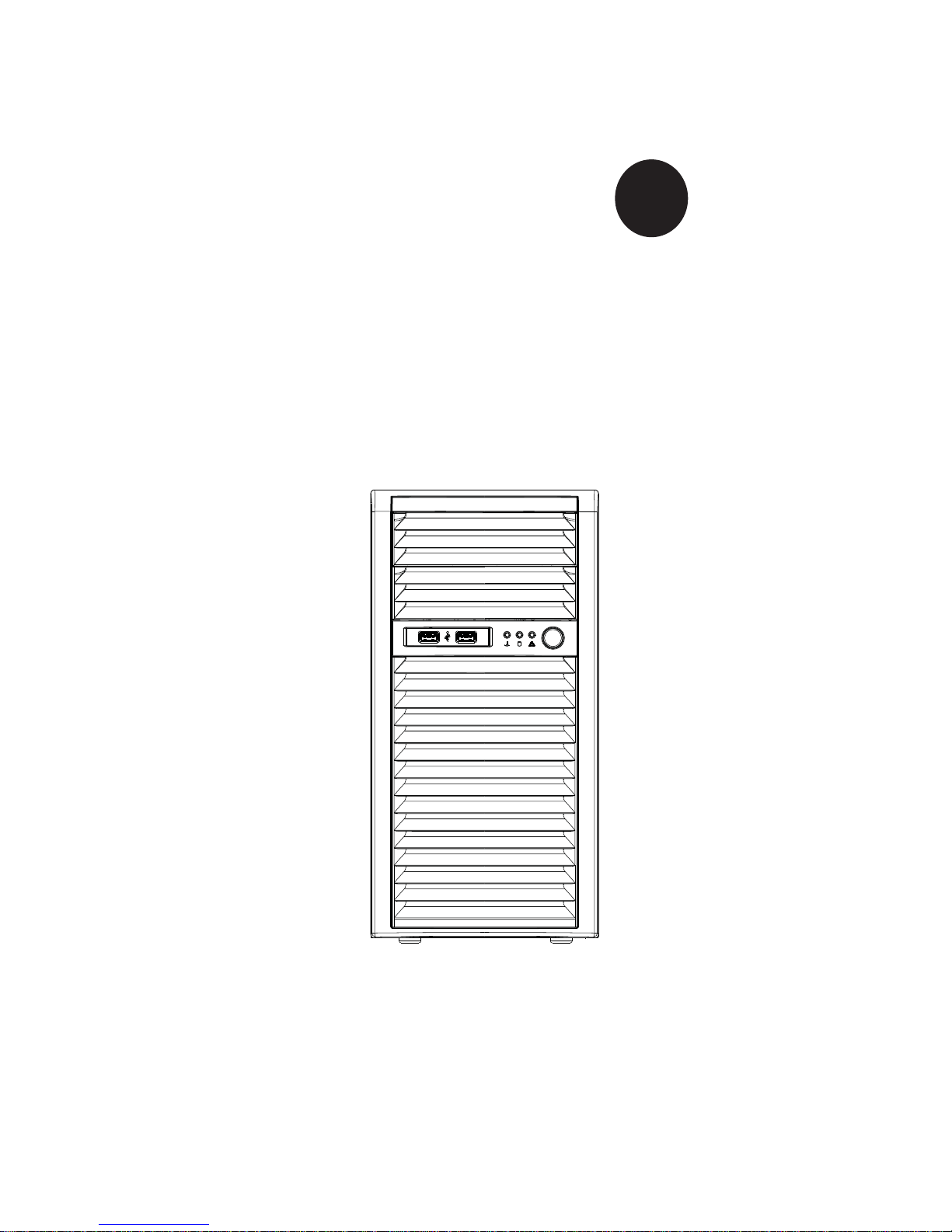
The SuperServer 5036I-I/5036I-IF is a single processor system based on the
SC731i-300 mini-tower chassis and the Super X8SIL/X8SIL-F motherboard.
Manual Organization
Chapter 1: Introduction
Preface
The fi rst chapter provides a checklist of the main components included with the
system and describes the main features of the Super X8SIL/X8SIL-F motherboard
and the SC731i-300 chassis.
Chapter 2: Installation
This chapter describes the steps necessary to setup the system. If your server was
ordered without the processor and memory components, this chapter will refer you
to the appropriate sections of the manual for their installation.
Chapter 3: System Interface
Refer to this chapter for details on the system interface, which includes the functions
and information provided by the control panel on the chassis as well as other LEDs
located throughout the system.
Chapter 4: System Safety
You should thoroughly familiarize yourself with this chapter for a general overview
of safety precautions that should be followed when installing and servicing the
SuperServer 5036I-I/5036I-IF.
Chapter 5: Advanced Motherboard Setup
Chapter 5 provides detailed information on the X8SIL/X8SIL-F motherboard, including the locations and functions of connectors, headers and jumpers. Refer
iii

SUPERSERVER 5036I-I/5036I-IF User's Manual
to this chapter when adding or removing processors or main memory and when
reconfi guring the motherboard.
Chapter 6: Advanced Chassis Setup
Refer to Chapter 6 for detailed information on the SC731i-300 chassis. You should
follow the procedures given in this chapter when installing, removing or reconfi gur-
ing Serial ATA or peripheral drives and when replacing system power supply units
and cooling fans.
Chapter 7: BIOS
The BIOS chapter includes an introduction to BIOS and provides detailed information on running the CMOS Setup Utility.
Appendix A: POST Error Beep Codes
Appendix B: Installing Windows
Appendix C: System Specifi cations
iv

Notes
Preface
v

SUPERSERVER 5036I-I/5036I-IF User's Manual
Table of Contents
Chapter 1 Introduction
1-1 Overview .........................................................................................................1-1
1-2 Motherboard Features .....................................................................................1-2
Processors ......................................................................................................1-2
Memory ...........................................................................................................1-2
Serial ATA ....................................................................................................... 1-2
PCI Expansion Slots ....................................................................................... 1-2
I/O Ports .......................................................................................................... 1-2
Other Features ................................................................................................ 1-2
1-3 Chassis Features ............................................................................................1-3
System Power ................................................................................................. 1-3
SATA Subsystem .............................................................................................1-3
Front Control Panel ......................................................................................... 1-3
Cooling System ............................................................................................... 1-3
1-4 Contacting Supermicro ....................................................................................1-5
Chapter 2 System Setup
2-1 Overview .........................................................................................................2-1
2-2 Unpacking the System .................................................................................... 2-1
2-3 Setting Up the System .................................................................................... 2-2
Checking the Motherboard Setup ................................................................... 2-2
Checking the Drive Bay Setup ........................................................................ 2-2
Chapter 3 System Interface
3-1 Overview .........................................................................................................3-1
3-2 Control Panel Button ....................................................................................... 3-1
Power ..............................................................................................................3-1
3-3 Control Panel LEDs ........................................................................................3-1
HDD ................................................................................................................. 3-1
NIC ..................................................................................................................3-2
Overheat/Fan Fail ........................................................................................... 3-2
Power On ........................................................................................................3-2
3-4 SATA Drive Carrier LEDs ................................................................................ 3-2
Chapter 4 System Safety
4-1 Electrical Safety Precautions .......................................................................... 4-1
4-2 General Safety Precautions ............................................................................ 4-2
4-3 ESD Precautions ............................................................................................. 4-3
4-4 Operating Precautions .................................................................................... 4-4
vi

Table of Contents
Chapter 5 Advanced Motherboard Setup
5-1 Handling the Motherboard .............................................................................. 5-1
Precautions .....................................................................................................5-1
Unpacking .......................................................................................................5-1
5-2 Motherboard Installation ..................................................................................5-2
5-3 Connecting Cables .......................................................................................... 5-2
Connecting Data Cables ................................................................................. 5-2
Connecting Power Cables .............................................................................. 5-3
Connecting the Control Panel .........................................................................5-3
5-4 I/O Ports .......................................................................................................... 5-4
5-5 Processor and Heatsink Installation................................................................5-4
Installing the LGA1156 Processor ................................................................. 5-5
Installing an Active CPU Heatsink .................................................................. 5-7
5-6 Installing Memory ..........................................................................................5-10
DIMM Installation .......................................................................................... 5-10
Memory Support ............................................................................................5-10
Memory Population Guidelines ......................................................................5-11
5-7 Installing PCI Add-On Cards ......................................................................... 5-13
5-8 Motherboard Details ...................................................................................... 5-15
5-9 Connector Defi nitions ...................................................................................5-17
Main ATX Power Supply Connector ......................................................... 5-17
Processor Power Connector .................................................................... 5-17
Power Button ...........................................................................................5-17
Reset Button ........................................................................................... 5-17
Overheat (OH)/Fan Fail ............................................................................ 5-18
NIC1/NIC2 (LAN1/LAN2) .......................................................................... 5-18
HDD LED ..................................................................................................5-18
Power On LED .........................................................................................5-18
Chassis Intrusion ...................................................................................... 5-19
ATX PS/2 Keyboard and PS/2 Mouse Ports ............................................ 5-19
Fan Headers .............................................................................................5-19
Onboard Speaker ..................................................................................... 5-19
Speaker ....................................................................................................5-20
Serial Ports ............................................................................................... 5-20
Universal Serial Bus (USB) ......................................................................5-20
LAN1/LAN2 (Ethernet Ports) ....................................................................5-20
Onboard Power LED ................................................................................ 5-21
Power Supply I
T-SGPIO 0/1 Headers .............................................................................. 5-21
2
C Connector....................................................................5-21
vii

SUPERSERVER 5036I-I/5036I-IF User's Manual
Alarm Reset ..............................................................................................5-21
5-10 Jumper Settings ............................................................................................5-22
Explanation of Jumpers ............................................................................5-22
CMOS Clear ............................................................................................. 5-22
VGA Enable ..............................................................................................5-22
LAN1/LAN2 Enable/Disable .................................................................... 5-23
PCI Slot SMB Enable ............................................................................... 5-23
USB Wake-Up ......................................................................................... 5-23
BMC Jumper ............................................................................................ 5-23
5-11 Onboard Indicators ........................................................................................5-24
LAN1/2 LEDs ............................................................................................5-24
IPMI Dedicated LAN LEDs ..................................................................... 5-24
Onboard Power LED
IPMI Heartbeat LED ................................................................................. 5-24
5-12 SATA and Floppy Drive Connections ............................................................ 5-25
SATA Ports ...............................................................................................5-25
Floppy Connector ..................................................................................... 5-25
............................................................................................................5-24
Chapter 6 Advanced Chassis Setup
6-1 Static-Sensitive Devices ..................................................................................6-1
Precautions .....................................................................................................6-1
Unpacking .......................................................................................................6-1
6-2 Front Control Panel ......................................................................................... 6-2
6-3 Front Bezel ...................................................................................................... 6-4
6-4 Removing the Chassis Cover ......................................................................... 6-5
6-5 System Fans ................................................................................................... 6-6
Fan Failure ...................................................................................................... 6-6
Replacing the System Fan .........................................................................6-6
6-6 Drive Bay Installation ......................................................................................6-7
SATA Drives ....................................................................................................6-7
Installing Drives in the Optional Drive Bays ................................................... 6-9
Chapter 7 BIOS
7-1 Introduction ......................................................................................................7-1
Starting BIOS Setup Utility ..............................................................................7-1
How To Change the Confi guration Data ......................................................... 7-1
How to Start the Setup Utility ......................................................................... 7-2
7-2 Main Setup ......................................................................................................7-2
7-3 Advanced Setup Confi gurations...................................................................... 7-4
7-4 Security Settings ........................................................................................... 7-20
viii

Table of Contents
7-5 Boot Settings ................................................................................................ 7-21
7-6 Exit Options ................................................................................................... 7-22
Appendix A POST Error Beep Codes
Appendix B Installing Windows
Appendix C System Specifi cations

SUPERSERVER 5036I-I/5036I-IF User's Manual
Notes

Chapter 1: Introduction
Chapter 1
Introduction
1-1 Overview
The SuperServer 5036I-I/5036I-IF is a high-end server comprised of two main subsystems: the SC731i-300 mini-tower chassis and the X8SIL/X8SIL-F motherboard.
Please refer to our web site for information on operating systems that have been
certifi ed for use with the SuperServer 5036I-I/5036I-IF (www.supermicro.com).
In addition to the motherboard and chassis, various hardware components have
been included with the SuperServer 5036I-I/5036I-IF, as listed below:
One cooling fan (FAN-0076L4)
•
One I/O shield (MCP-260-00027-0N)•
SATA Accessories •
Four SATA cables (CBL-0044L)
One SuperServer 5036I-I/5036I-IF User's Manual
•
Optional
One active heatsink (SNK-P0046A4)
•
One intake fan (FAN-0113L4)•
One DVD-ROM drive (DVM-LITE-DVDRW-HBT or DVM-LITE-DVD-HBT)•
1-1

SUPERSERVER 5036I-I/5036I-IF User's Manual
1-2 Motherboard Features
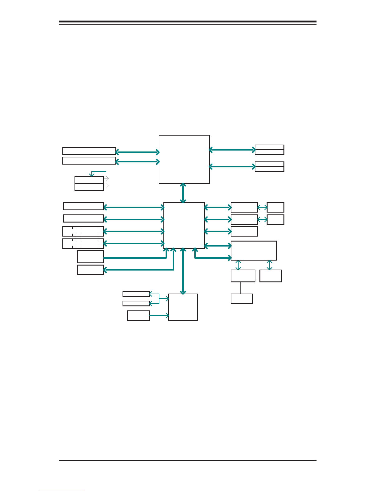
At the heart of the SuperServer 5036I-I/5036I-IF lies the X8SIL/X8SIL-F, a single
processor motherboard based on the Intel® 3400 (X8SIL) and Intel 3420 (X8SIL-F)
chipsets. Below are the main features of the X8SIL/X8SIL-F. (See Figure 1-1 for a
block diagram of the chipset).
Processors
The X8SIL/X8SIL-F supports a single Intel® 3400 series processor in an LGA1156
socket. Please refer to the motherboard description pages on our web site for a
complete listing of supported processors (www.supermicro.com).
Memory
The X8SIL/X8SIL-F has four DIMM slots that can support up to 16 GB of UDIMM
(unbuffered DIMMs) or up to 32 GB or RDIMM (registered DIMMs) DDR3-1333/1066/800 memory. Dual-channel confi gurations are supported. Memory modules
of the same size and speed should be used. See Chapter 5 for details.
Serial ATA
A SATA controller is integrated into the chipset to provide a 3 Gb/s Serial ATA subsystem, which is RAID 0, 1, 10 and (Windows only) 5 capable. The SATA drives
are hot-swappable units. The X8SIL has four SATA ports while the X8SIL-F has
six SATA ports.
PCI Expansion Slots
The X8SIL/X8SIL-F has two PCI-Express 2.0 x8 slots, one PCI-Express 2.0 x4 (in
a x8 slot) and one 32-bit PCI 33 MHz slot.
I/O Ports
The color-coded I/O ports include a COM port, two USB 2.0 ports, PS/2 mouse
and keyboard ports and two Gb Ethernet ports. An IPMI LAN port is also included
on the X8SIL-F.
Other Features
Other onboard features that promote system health include onboard voltage monitors, a chassis intrusion header, 3-phase switching voltage regulators, chassis and
CPU overheat sensors, Thermal Monitor 2 (TM2) support and a BIOS fl ash upgrade
utility.
1-2

Chapter 1: Introduction
1-3 Chassis Features
The SC731i-300 is a mini-tower chassis with a unique design that allows most
confi gurations to be performed without the need for tools The following is a general
outline of the main features of the SC731i-300 chassis.
System Power
The SC731i-300 features a high-effi ciency 300W power supply. Power must be
removed from the system before servicing or replacing the power supply.
SATA Subsystem
The chass is was desi gned to su ppor t four S ATA har d drive s.
Front Control Panel
The control panel provides you with system monitoring and control. LEDs indicate
network activity, hard disk drive activity and overheat conditions. The control panel
also includes a main power button, which has a blue LED that illuminates when
the system is powered on.
Cooling System
The SC731i-300 chassis includes one whisper-quiet 9-cm exhaust fan located at
the rear of the chassis and an 8-cm fan located in the power supply. Both fans
operate continuously.
1-3
SUPERSERVER 5036I-I/5036I-IF User's Manual
Figure 1-1. Intel 3400/3420 Chipset:
System Block Diagram
Note: This is a general block diagram. Please see Chapter 5 for details.
PCIe x8 SLOT
PCIe x8 SLOT
VID[0-7]
VRM 11.1
MISC VRs
PCIe x8 SLOT
1 PCI 32 SLOT
4/6 SATA PORTS
5/7 USB PORTS
CK505
Rev1.0
FLASH
SPI 16Mb
PCIe2.0_x8
5.0Gb
PCIe2.0_x8
5.0Gb
PCIe_x4
2.5Gbps
PCI 32
SATA-II
300MB/s
USB2.0
480Mbps
CLOCK
SPI
COM1,2
P/S2
HEALTH
INFO
Xeon 3400
Series
2.5Gb
x4 DMI
IBexPeak
Intel 3400/3420
PCH
LPC
W83627DHG
LPC I/O
DDR3 (CHA)
1333/1066MHz
DDR3 (CHB)
1333/1066MHz
PCIe_x1
2.5Gbps
PCIe_x1
2.5Gbps
LPC
PCI32
LPC
DIMM1(Far)
DIMM2
DIMM1(Far)
DIMM2
GLAN1
82574L
GLAN2
82574L
TPM1.2
HERMON WPCM450
WINBOND
RTL8201N
PHY
RJ45
RMII
P15
(option)
RJ45
RJ45
VGA
PORT
4 UDIMM
4 RDIMM
(4 Quad rank
RDIMM run on
800MHz)
1-4

Chapter 1: Introduction
1-4 Contacting Supermicro
Headquarters
Address: Super Micro Computer, Inc.
980 Rock Ave.
San Jose, CA 95131 U.S.A.
Tel: +1 (408) 503-8000
Fax: +1 (408) 503-8008
Email: marketing@supermicro.com (General Information)
support@supermicro.com (Technical Support)
Web Site: www.supermicro.com
Europe
Address: Super Micro Computer B.V.
Het Sterrenbeeld 28, 5215 ML
's-Hertogenbosch, The Netherlands
Tel: +31 (0) 73-6400390
Fax: +31 (0) 73-6416525
Email: sales@supermicro.nl (General Information)
support@supermicro.nl (Technical Support)
rma@supermicro.nl (Customer Support)
Asia-Pacifi c
Address: Super Micro Computer, Inc.
4F, No. 232-1, Liancheng Rd.
Chung-Ho 235, Taipei County
Taiwan, R.O.C.
Tel: +886-(2) 8226-3990
Fax: +886-(2) 8226-3991
Web Site: www.supermicro.com.tw
Technical Support:
Email: support@supermicro.com.tw
Tel: 886-2-8228-1366, ext.132 or 139
1-5

SUPERSERVER 5036I-I/5036I-IF User's Manual
Notes
1-6
Chapter 2: System Setup
!
!
Chapter 2
System Setup
2-1 Overview
This chapter provides a quick setup checklist to get your SuperServer 5036I-I/5036IIF up and running. Following the steps in the order given should enable you to
have the system operational within a minimal amount of time. If your system is
not already fully integrated with a motherboard, processor, system memory etc.,
please turn to the chapter or section noted in each step for details on installing
specifi c components.
2-2 Unpacking the System
You should inspect the box the SuperServer 5036I-I/5036I-IF was shipped in and
note if it was damaged in any way. If the server itself shows damage, you should
fi le a damage claim with the carrier who delivered it.
Decide on a suitable location for setting up and operating the SuperServer 5036II/5036I-IF. It should be situated in a clean, dust-free area that is well ventilated.
Avoid areas where heat, electrical noise and electromagnetic fi elds are generated.
You will also need it placed near a grounded power outlet.
Warnings and Precautions!
Review the electrical and general safety precautions in Chapter 4.•
Use a regulating uninterruptible power supply (UPS) to protect the server from •
power surges, voltage spikes and to keep your system operating in case of a
power failure.
Allow the power supply units and Serial ATA drives to cool before touching
•
them.
To maintain proper cooling, always keep all chassis panels closed when not
•
being serviced.
2-1
SUPERSERVER 5036I-I/5036I-IF User's Manual
!
2-3 Setting Up the System
You should fi rst open the left side panel (when facing the front of the chassis) to
make sure the motherboard is properly installed and all connections have been
made.
Warning: Only qualifi ed service technicians should access the inside of
the system. Except for short periods of time, do NOT operate the system
without the cover in place. The chassis cover must be in place to allow
proper airfl ow and prevent overheating.
Checking the Motherboard Setup
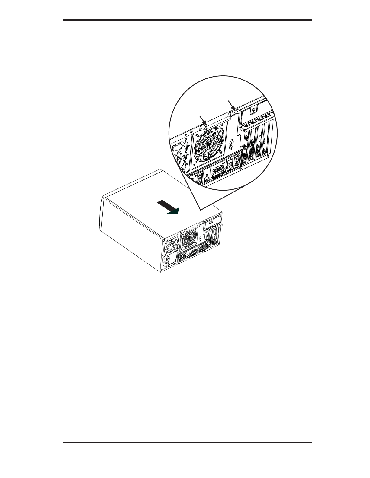
Accessing the inside of the system (Figure 2-1): Begin by disconnecting the 1.
chassis from any power source. Grasp the cover handle (A) with your fi ngers.
Use your thumb to lift the cover latch (B). Slide the cover back, toward the
rear of the chassis, then lift the cover off.
Check the CPU (processor): You may have a processor already installed into 2.
the system board. The processor should have its own heatsink attached. See
Chapter 5 for instructions on processor installation.
Check the system memory:3. Your system may have come with system
memory already installed. Make sure all DIMMs are fully seated in their slots.
For details on adding system memory, refer to Chapter 5.
Installing add-on cards:4. If desired, you can install up to six add-on cards to
the system. See Chapter 5 for details on installing PCI- add-on cards.
Check all cable connections and airfl ow: Make sure all power and data cables 5.
are properly connected and not blocking the airfl ow. See Chapter 5 for details
on cable connections.
Checking the Drive Bay Setup
Next, you should check to make sure the peripheral drives and the SA T A drives have
been properly installed and all essential connections have been made.
Accessing the peripheral drive bays: To install a component to either of the 1.
two 5.25" drive bays, you will need to remove the side chassis cover. See the
installation and removal sections for the peripheral drives in Chapter 6.
2-2
Chapter 2: System Setup
Figure 2-1. Accessing the Inside of the System
3
Release Tab (B)
Handle (A)
1
2-3

SUPERSERVER 5036I-I/5036I-IF User's Manual
Check the SATA disk drives: Depending upon your system's confi guration, 2.
your system may have up to four SATA drives already installed. If you need
to install or remove an SATA drive, please refer to the appropriate section in
Chapter 6.
Check the airfl ow: Cooling air is provided by the chassis fan and the power 3.
supply fan. The system component layout was carefully designed to promote
suffi cient airfl ow throughout the chassis. Also note that all power and data
cables have been routed in such a way that they do not block the airfl ow
generated by the fan. Please keep this in mind when rerouting or adding/
removing cables.
Supplying power to the system: The last thing you must do is to provide input 4.
power to the system. Plug the power cord from the power supply unit into a
high-quality power strip that offers protection from electrical noise and power
surges. It is recommended that you use an uninterruptible power supply
(UPS).
2-4

Chapter 3: System Interface
Chapter 3
System Interface
3-1 Overview
There are four LEDs on the control panel to keep you constantly informed of the
overall status of the system as well as the activity and health of specifi c components.
The control panel also is where to fi nd the main power on/off button.
3-2 Control Panel Button
Power
The main p ower switc h is used to a pply or re move power fr om the po wer supply
to the server syste m. Turning o ff system po wer w i th t h is b utton rem oves t h e ma in
power but keeps standby power supplied to the system. Therefore, you must
unplug system before servicing.
3-3 Control Panel LEDs
The control panel located on the front of the SC731i-300B chassis has four LEDs.
These LEDs provide you with critical information related to different parts of the
system. This section explains what each LED indicates when illuminated and any
corrective action you may need to take.
HDD
This LED indicates SATA drive and/or DVD-ROM drive activity when fl ashing.
3-1
SUPERSERVER 5036I-I/5036I-IF User's Manual
NIC
Indicates network activity on a Gigabit LAN port when fl ashing.
Overheat/Fan Fail
When this LED fl ashes it indicates a fan failure. When on continuously (on and not
fl ashing) it indicates an overheat condition, which may be caused by cables ob-
structing the airfl ow in the system or the ambient room temperature being too warm.
Check the routing of the cables and make sure all fans are present and operating
normally. You should also check to make sure that the chassis covers are installed.
Finally, verify that the heatsinks are installed properly (see Chapter 5). This LED
will remain fl ashing or on as long as the overheat condition exists.
Power On
A blue LED located behind the main power button is illuminated when the system
is powered on and running.
3-4 SATA Drive Carrier LEDs
Green:• Each SATA drive carrier has a green LED. When illuminated, this
green LED (on th e front of the SATA drive c arrier) indi cates drive ac tivity. A
conne cti on to th e SATA ba ckp lane ena bles t his LED to b link on a nd of f when
that particular drive is being accessed. Please refer to Chapter 6 for instructions
on replacing failed SATA drives.
Red:
• The red LED to indicate an SATA drive failure. If one of the SATA drives
fail, you should be notifi ed by your system management software. Please refer
to Chapter 6 for instructions on replacing failed SATA drives.
3-2
Chapter 4: System Safety
!
Chapter 4
System Safety
4-1 Electrical Safety Precautions
Note: power should always be disconnected before performing any service on the system.
Basic electrical safety precautions shall be followed to protect yourself from harm
and the SuperServer 5036I-I/5036I-IF from damage:
Be aware of the locations of the power on/off switch on the chassis as well
•
as the room's emergency power-off switch, disconnection switch or electrical
outlet. If an electrical accident occurs, you can then quickly remove power from
the system.
Do not work alone when working with high voltage components.
•
Power should always be disconnected from the system when removing or in-•
stalling main system components, such as the serverboard, memory modules
and fl oppy drive. When disconnecting power, you should fi rst power down the
system with the operating system fi rst and then unplug the power cords of all
the power supply units in the system.
When working around exposed electrical circuits, another person who is familiar
•
with the power-off controls should be nearby to switch off the power if necessary.
Use only one hand when working with powered-on electrical equipment. This
•
is to avoid making a complete circuit, which will cause electrical shock. Use
extreme caution when using metal tools, which can easily damage any electrical
components or circuit boards they come into contact with.
Do not use mats designed to decrease static electrical discharge as protection
•
from electrical shock. Instead, use rubber mats that have been specifi cally
designed as electrical insulators.
The power supply power cords must include a grounding plug and must be
•
plugged into grounded electrical outlets.
4-1
SUPERSERVER 5036I-I/5036I-IF User's Manual
!
This product may be connected to an IT power system. In all cases, make sure •
that the unit is also reliably connected to Earth (ground).
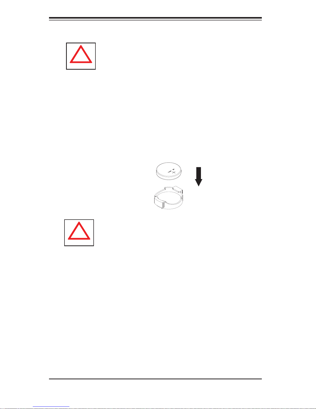
Serverboard Battery:
• CAUTION - There is a danger of explosion if the onboard
battery is installed upside down, which will reverse its polarites (see Figure
4-1). This battery must be replaced only with the same or an equivalent type
recommended by the manufacturer. Dispose of used batteries according to the
manufacturer's instructions.
DVD-ROM Laser:
• CAUTION - this server may have come equipped with a
DVD-ROM drive. To prevent direct exposure to the laser beam and hazardous
radiation exposure, do not open the enclosure or use the unit in any unconventional way.
Mainboard replaceable soldered-in fuses: Self-resetting PTC (Positive Tempera-
•
ture Coeffi cient) fuses on the mainboard must be replaced by trained service
technicians only. The new fuse must be the same or equivalent as the one
replaced. Contact technical support for details and support.
4-2 General Safety Precautions
Follow these rules to ensure general safety:
Keep the area around the SuperServer 5036I-I/5036I-IF clean and free of clut-
•
ter.
The SuperServer 5036I-I/5036I-IF weighs approximately 43 lbs. (19.5 kg) when
•
fully loaded. When lifting the system, two people at either end should lift slowly
with their feet spread out to distribute the weight. Always keep your back straight
and lift with your legs.
Place the chassis top cover and any system components that have been re-
•
moved away from the system or on a table so that they won't accidentally be
stepped on.
While working on the system, do not wear loose clothing such as neckties and
•
unbuttoned shirt sleeves, which can come into contact with electrical circuits or
be pulled into a cooling fan.
4-2
Chapter 4: System Safety
!
Remove any jewelry or metal objects from your body, which are excellent metal •
conductors that can create short circuits and harm you if they come into contact
with printed circuit boards or areas where power is present.
After accessing the inside of the system, close the system back up and secure
•
it to the rack unit with the retention screws after ensuring that all connections
have been made.
4-3 ESD Precautions
Electrostatic Discharge (ESD) is generated by two objects with different electrical
charges coming into contact with each other. An electrical discharge is created to
neutralize this difference, which can damage electronic com ponents and printed
circuit boards. The following measures are generally suffi cient to neutralize this
difference before contact is made to protect your equipment from ESD:
Use a grounded wrist strap designed to prevent static discharge.
•
Keep all components and printed circuit boards (PCBs) in their antistatic bags •
until ready for use.
Touch a grounded metal object before removing the board from the antistatic
•
bag.
Do not let components or PCBs come into contact with your clothing, which may
•
retain a charge even if you are wearing a wrist strap.
Handle a board by its edges only; do not touch its components, peripheral chips,
•
memory modules or contacts.
When handling chips or modules, avoid touching their pins.
•
Put the serverboard and peripherals back into their antistatic bags when not •
in use.
For grounding purposes, make sure your computer chassis provides excellent
•
conductivity between the power supply, the case, the mounting fasteners and
the serverboard.
4-3
SUPERSERVER 5036I-I/5036I-IF User's Manual
!
!
4-4 Operating Precautions
Care must be taken to assure that the chassis cover is in place when the 5036II/5036I-IF is operating to assure proper cooling. Out of warranty damage to the
system can occur if this practice is not strictly followed.
Figure 4-1. Installing the Onboard Battery
LITHIUM BATTERY
BATTERY HOLDER
Please handle used batteries carefully. Do not damage the battery in any way; a
damaged battery may release hazardous materials into the environment. Do not
discard a used battery in the garbage or a public landfi ll. Please comply with the
regulations set up by your local hazardous waste management agency to dispose
of your used battery properly.
4-4
Chapter 5: Advanced Motherboard Setup
Chapter 5
Advanced Motherboard Setup
This chapter covers the steps required to install the X8SIL/X8SIL-F motherboard
into the chassis, connect the data and power cables and install add-on cards. All
jumpers and connections are described and a layout and quick reference chart are
included for your reference. Remember to completely close the chassis when you
have fi nished working with the motherboard to better cool and protect the system.
5-1 Handling the Motherboard
Electrostatic Discharge (ESD) can damage electronic com ponents. To prevent damage to any printed circuit boards (PCBs), it is important to handle them very carefully
(see previous chapter). To prevent the motherboard from bending, keep one hand
under the center of the board to support it when handling. The following measures
are generally suffi cient to protect your equipment from electric static discharge.
Precautions
Use a grounded wrist strap designed to prevent Electrostatic Discharge.•
Touch a grounded metal object before removing any board from its antistatic •
bag.
Handle a board by its edges only; do not touch its components, peripheral chips,
•
memory modules or gold contacts.
When handling chips or modules, avoid touching their pins.
•
Put the motherboard, add-on cards and peripherals back into their antistatic •
bags when not in use.
For grounding purposes, make sure your computer chassis provides excellent
•
conductivity between the power supply, the case, the mounting fasteners and
the motherboard.
Unpacking
The motherboard is shipped in antistatic packaging to avoid electrical static discharge. When unpacking the board, make sure the person handling it is static
protected.
5-1

SUPERSERVER 5036I-I/5036I-IF User's Manual
5-2 Motherboard Installation
This section explains the fi rst step of physically mounting the X8SIL/X8SIL-F into the
SC731i-300 chassis. Following the steps in the order given will eliminate the most
common problems encountered in such an installation. To remove the motherboard,
follow the procedure in reverse order.
Installing to the Chassis
Access the inside of the system (see procedure in Chapter 6).1.
Make sure that the I/O ports on the motherboard align properly with their 2.
respective holes in the I/O shield at the back of the chassis.
Carefully mount the motherboard to the motherboard tray by aligning the 3.
board holes with the raised metal standoffs that are visible in the chassis. You
may need to add an extra standoff for the hole near the Fan 3 header.
Insert screws into all the mounting holes on your motherboard that line up 4.
with the standoffs and tighten until snug (if you screw them in too tight, you
might strip the threads).
Finish by replacing the top cover of the chassis.5.
Note: Metal screws provide an electrical contact to the serverboard ground to
provide a continuous ground for the system.
Warning: To avoid damaging the serverboard and its components, do not apply
any force greater than 8 lbs. per square inch when installing a screw into a mounting hole.
5-3 Connecting Cables
Now that the motherboard is installed, the next step is to connect the cables to the
board. These include the data (ribbon) cables for the peripherals and control panel
and the power cables.
Connecting Data Cables
The cables used to transfer data from the peripheral devices have been carefully
routed to prevent them from blocking the fl ow of cooling air that moves through
the system from front to back. If you need to disconnect any of these cables, you
should take care to keep them routed as they were originally after reconnecting
them (make sure the red wires connect to the pin 1 locations). The following data
5-2
Chapter 5: Advanced Motherboard Setup
cables (with their locations noted) should be connected. (See the layout on page
5-9 for connector locations.)
SATA drive data cable (I-SATA0 ~ I-SATA3)
•
Control Panel cable (JF1)•
Important! Make sure the the cables do not come into contact with the fans.
Connecting Power Cables
The X8SIL/X8SIL-F has a 24-pin primary power supply connector (JPW1) for connection to the ATX power supply. In addition, an 8-pin processor power connector
(JPW2) must also be connected to your power supply. See Section 5-9 for power
connector pin defi nitions.
Connecting the Control Panel
JF1 contains header pins for various front control panel connectors. See Figure 5-1
for the pin locations of the various front control panel buttons and LED indicators.
All JF1 wires have been bundled into a single ribbon cable to simplify this connection. Make sure the red wire plugs into pin 1 as marked on the board. The other
end connects to the Control Panel PCB board, located just behind the system status
LEDs on the chassis. See Chapter 5 for details and pin descriptions.
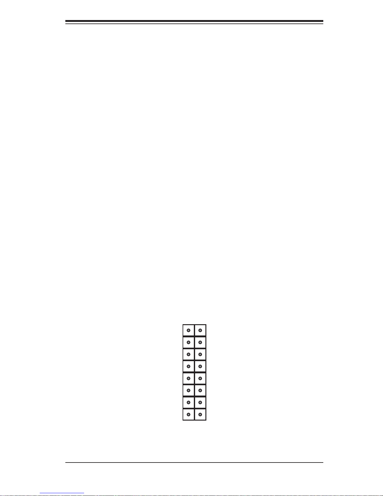
Figure 5-1. Control Panel Header Pins
16 15
Power LED
HDD LED
NIC1 LED
NIC2 LED
OH/Fan Fail LED
LED Anode
LED Anode
LED Anode
LED Anode
LED Anode
x (Key)
Ground
Ground
x (Key)
Reset (Button)
Power (Button)
2 1
5-3
 Loading...