

Page 1
SUPER
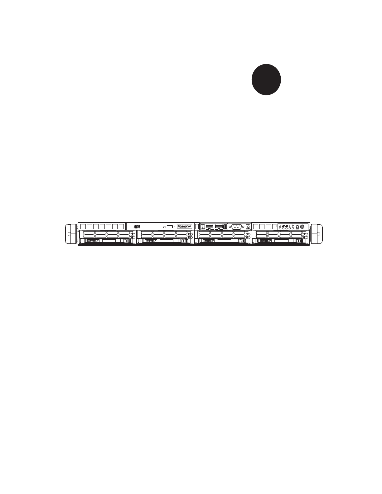
SUPERSERVER 5015B-MT
®
USER’S MANUAL
Revision 1.0a
Page 2

The information in this User’s Manual has been carefully reviewed and is believed to be accurate.
The vendor assumes no responsibility for any inaccuracies that may be contained in this document,
makes no commitment to update or to keep current the information in this manual, or to notify any
person or organization of the updates. Please Note: For the most up-to-date version of this
manual, please see our web site at www.supermicro.com.
Super Micro Computer, Inc. ("Supermicro") reserves the right to make changes to the product
described in this manual at any time and without notice. This product, including software, if any,
and documentation may not, in whole or in part, be copied, photocopied, reproduced, translated or
reduced to any medium or machine without prior written consent.
IN NO EVENT WILL SUPERMICRO BE LIABLE FOR DIRECT, INDIRECT, SPECIAL, INCIDENTAL,
SPECULATIVE OR CONSEQUENTIAL DAMAGES ARISING FROM THE USE OR INABILITY TO
USE THIS PRODUCT OR DOCUMENTATION, EVEN IF ADVISED OF THE POSSIBILITY OF
SUCH DAMAGES. IN PARTICULAR, SUPERMICRO SHALL NOT HAVE LIABILITY FOR ANY
HARDWARE, SOFTW ARE, OR DA TA STORED OR USED WITH THE PRODUCT, INCLUDING THE
COSTS OF REPAIRING, REPLACING, INTEGRATING, INSTALLING OR RECOVERING SUCH
HARDWARE, SOFTWARE, OR DATA.
Any disputes arising between manufacturer and customer shall be governed by the laws of Santa
Clara County in the State of California, USA. The State of California, County of Santa Clara shall
be the exclusive venue for the resolution of any such disputes. Super Micro's total liability for
all claims will not exceed the price paid for the hardware product.
FCC Statement: This equipment has been tested and found to comply with the limits for a Class
A digital device pursuant to Part 15 of the FCC Rules. These limits are designed to provide
reasonable protection against harmful interference when the equipment is operated in a commercial
environment. This equipment generates, uses, and can radiate radio frequency energy and, if not
installed and used in accordance with the manufacturer’s instruction manual, may cause harmful
interference with radio communications. Operation of this equipment in a residential area is likely
to cause harmful interference, in which case you will be required to correct the interference at your
own expense.
California Best Management Practices Regulations for Perchlorate Materials: This Perchlorate
warning applies only to products containing CR (Manganese Dioxide) Lithium coin cells. “Perchlorate
Material-special handling may apply. See www.dtsc.ca.gov/hazardouswaste/perchlorate”
WARNING: Handling of lead solder materials used in this
product may expose you to lead, a chemical known to
the State of California to cause birth defects and other
reproductive harm.
Manual Revision 1.0a
Release Date: July 20, 2009
Unless you request and receive written permission from Super Micro Computer, Inc., you may not
copy any part of this document.
Information in this document is subject to change without notice. Other products and companies
referred to herein are trademarks or registered trademarks of their respective companies or mark
holders.
Copyright © 2009 by Super Micro Computer, Inc.
All rights reserved.
Printed in the United States of America
Page 3

Preface
About This Manual
This manual is written for professional system integrators and PC technicians. It provides information for the installation and use of the SuperServer 5015B-MT. Installation and maintainance should be performed by experienced technicians only.
The SuperServer 5015B-MT is a high-end single processor 1U rackmount server
based on the SC813MTQ-300C server chassis and the X7SBi motherboard. The
X7SBi supports single Intel
bus spee ds of 1333/106 6/8 00 MH z.
® Xeon® 3000 Series/3200 Series Processor at s ystem
Preface
Manual Organization
Chapter 1: Introduction
The fi rst chapter provides a checklist of the main components included with the
server system and describes the main features of the Super X7SBi motherboard
and the SC813MTQ-300C chassis.
Chapter 2: Server Installation
This chapter describes the steps necessary to install the SuperServer 5015B-MT
into a rack and check out the server confi guration prior to powering up the system. If
your server was ordered without the processor and memory components, this chapter will refer you to the appropriate sections of the manual for their installation.
Chapter 3: System Interface
Refer to this chapter for details on the system interface, which includes the functions
and information provided by the control panel on the chassis as well as other LEDs
located throughout the system.
iii
Page 4

SUPERSERVER 5015B-MT User's Manual
Chapter 4: System Safety
You should thoroughly familiarize yourself with this chapter for a general overview
of safety precautions that should be followed when installing and servicing the
SuperServer 5015B-MT.
Chapter 5: Advanced Motherboard Setup
Chapter 5 provides detailed information on the X7SBi motherboard, including the
locations and functions of connectors, headers and jumpers. Refer to this chapter
when adding or removing processors or main memory and when reconfi guring the
motherboard.
Chapter 6: Advanced Chassis Setup
Refer to Chapter 6 for detailed information on the SC813MTQ-300C 1U rackmount
server chassis. You should follow the procedures given in this chapter when installing, removing or reconfi guring Serial ATA or peripheral drives and when replacing
system power supply units and cooling fans.
Chapter 7: BIOS
The BIOS chapter includes an introduction to BIOS and provides detailed information on running the CMOS Setup Utility.
Appendix A: BIOS POST Messages
Appendix B: BIOS POST Codes
Appendix C: System Specifi cations
iv
Page 5

Notes
Preface
v
Page 6

SUPERSERVER 5015B-MT User's Manual
Table of Contents
Chapter 1 Introduction
1-1 Overview .........................................................................................................1-1
1-2 Motherboard Features .....................................................................................1-2
Processor ........................................................................................................1-2
Memory ...........................................................................................................1-2
Onboard SATA .................................................................................................1-2
PCI Expansion Slots ....................................................................................... 1-2
Onboard Controllers/Ports .............................................................................. 1-2
1-3 Server Chassis Features ................................................................................ 1-4
System Power .................................................................................................1-4
Control Panel .................................................................................................. 1-4
Rear I/O Panel ................................................................................................1-4
1-4 Contacting Supermicro ....................................................................................1-5
Chapter 2 Server Installation
2-1 Overview .........................................................................................................2-1
2-2 Unpacking the System ....................................................................................2-1
2-3 Preparing for Setup ......................................................................................... 2-1
Choosing a Setup Location .............................................................................2-1
Rack Precautions ............................................................................................2-2
Server Precautions ..........................................................................................2-2
Rack Mounting Considerations .......................................................................2-3
Ambient Operating Temperature ................................................................ 2-3
Reduced Airfl ow ......................................................................................... 2-3
Mechanical Loading ................................................................................... 2-3
Circuit Overloading ..................................................................................... 2-3
Reliable Ground ......................................................................................... 2-3
2-4 Installing the System into a Rack ................................................................... 2-4
Identifying the Sections of the Rack Rails ...................................................... 2-4
Installing the Rear Inner Rails ........................................................................ 2-4
Installing the Rack Rails .................................................................................2-5
Installing the Server into the Rack ..................................................................2-6
Installing the Server into a Telco Rack ........................................................... 2-7
2-5 Checking the Motherboard Setup ...................................................................2-8
2-6 Checking the Drive Bay Setup ........................................................................2-9
vi
Page 7

Table of Contents
Chapter 3 System Interface
3-1 Overview .........................................................................................................3-1
3-2 Control Panel Buttons .....................................................................................3-1
Reset ...............................................................................................................3-1
Power ..............................................................................................................3-1
3-3 Control Panel LEDs ........................................................................................3-2
Overheat/Fan Fail ........................................................................................... 3-2
NIC2 ................................................................................................................3-2
NIC1 ................................................................................................................3-2
HDD ................................................................................................................. 3-2
Power ..............................................................................................................3-3
3-4 SATA Drive Carrier LEDs ................................................................................ 3-3
Chapter 4 System Safety
4-1 Electrical Safety Precautions .......................................................................... 4-1
4-2 General Safety Precautions ............................................................................4-2
4-3 ESD Precautions ............................................................................................. 4-3
4-4 Operating Precautions .................................................................................... 4-4
Chapter 5 Advanced Serverboard Setup
5-1 Handling the Serverboard ...............................................................................5-1
Precautions .....................................................................................................5-1
Unpacking .......................................................................................................5-2
5-2 Serverboard Installation ..................................................................................5-2
5-3 Connecting Cables .......................................................................................... 5-3
Connecting Data Cables .................................................................................5-3
Connecting Power Cables .............................................................................. 5-3
Connecting the Control Panel ......................................................................... 5-3
5-4 I/O Ports .......................................................................................................... 5-4
5-5 Installing the Processors and Heat Sinks ....................................................... 5-5
5-6 Installing Memory ............................................................................................5-8
Memory Support ..............................................................................................5-8
5-7 Adding PCI Expansion Cards ......................................................................... 5-9
5-8 Serverboard Details ...................................................................................... 5-10
X7SBi Quick Reference .................................................................................5-11
5-9 Connector Defi nitions ...................................................................................5-12
5-10 Jumper Settings ............................................................................................5-17
5-11 Onboard Indicators ........................................................................................5-19
5-12 Floppy, SATA, IPMI, IDE and Printer Ports ...................................................5-20
5-13 Installing Drivers ............................................................................................ 5-22
vii
Page 8

SUPERSERVER 5015B-MT User's Manual
Supero Doctor III ........................................................................................... 5-23
Chapter 6 Advanced Chassis Setup
6-1 Static-Sensitive Devices ..................................................................................6-1
Precautions .....................................................................................................6-1
Unpacking .......................................................................................................6-1
6-2 Control Panel ..................................................................................................6-2
6-3 System Fans ................................................................................................... 6-3
6-4 Drive Bay Installation/Removal .......................................................................6-3
Removing the Front Bezel .............................................................................. 6-3
Serial ATA Drive Installation ............................................................................6-4
Accessing the Drive Bays ...............................................................................6-4
Serial ATA Backplane ......................................................................................6-5
6-5 Power Supply ..................................................................................................6-7
Power Supply Failure ...................................................................................... 6-7
Chapter 7 BIOS
7-1 Introduction ......................................................................................................7-1
7-2 Running Setup ................................................................................................ 7-2
7-3 Main BIOS Setup ............................................................................................ 7-2
7-4 Advanced Setup .............................................................................................. 7-7
7-5 Security Settings ........................................................................................... 7-23
7-6 Boot Settings ................................................................................................. 7-25
7-7 Exit ................................................................................................................ 7-26
Appendix A BIOS POST Messages
Appendix B BIOS POST Codes
Appendix C System Specifi cations
viii
Page 9

Chapter 1: Introduction
Chapter 1
Introduction
1-1 Overview
The Supermicro SuperServer 5015B-MT is a high-end single processor, 1U rackmount server with state-of-the-art features. The 5015B-MT is comprised of two main
subsystems: the SC813MTQ-300C 1U chassis and the X7SBi motherboard. Please
refer to our web site for information on operating systems that have been certifi ed
for use with the 5015B-MT.
In addition to the mainboard and chassis, various hardware components may have
been included with the 5015B-MT, as listed below.
One CPU heatsink (SNK-P0016P)
One (1) slim DVD-ROM drive [DVM-PNSC-824(B)]
Four (4) 4-cm fans (FAN-0061L)
One (1) air shroud (MCP-310-18009-0N)
Serial ATA (SATA) Accessories:
One (1) internal SATA backplane (BPN-SAS-815TQ)
One (1) set of SATA cables (CBL-0186L)
One (1) SGPIO cable (CBL-0157L)
Four (4) SATA drive carriers [CSE-PT39 (B)]
One (1) PCI-E x8 slot riser card (CSE-RR1U-ELi)
One (1) 64-bit PCI-X slot riser card (CSE-RR1U-Xi)
Rackmount hardware with screws (CSE-PT52)
One (1) CD containing drivers and utilities
SuperServer 5015B-MT User's Manual
Note: "B" indicates black.
1-1
Page 10

SUPERSERVER 5015B-MT User's Manual
1-2 Motherboard Features
At the heart of the SuperServer 5015B-MT lies the X7SBi, a single processor
motherboard based upon Intel's E3210 chipset. Below are the main features of
the X7SBi.
Processor
The X7SBi supports single Intel Xeon 3200/3000 Series LGA775 processors at
system bus speeds of 1333, 1066 and 800 MHz. Please refer to the motherboard
specifi cations pages on our web site for updates on supported processors.
Memory
The X7SBi has four 240-pin DIMM slots that can support up to 8 GB of unbuffered
ECC DDR2-800/667 SDRAM.
Onboard SATA
A SATA controller is built in to the ICH9R portion of the chipset to provide support
for a six port, 3 Gb/sec Se ria l ATA sub system, whi ch is R A ID 0, 1, 5 and 10 supported. The SATA drives are hot-swappable units. Note: The operating system
you use must have RAID support to enable the hot-swap capability and R AID
function of the SATA drives.
PCI Expansion Slots
The X7SBi has one universal PCI-Express x8 slot, one 64-bit 133 MHz PCI-X slot
and one PCI 33 MHz slot. Either the PCI-E slot or the PCI-X slot may be populated
with the use of a riser card (included).
Onboard Controllers/Ports
An onboard IDE controller supports one fl oppy drive and up to two Ultra ATA 100
hard drives or ATAPI devices. Onboard I/O backpanel ports include one COM port,
a VGA port, two USB ports, PS/2 mouse and keyboard ports and two Gigabit LAN
(NIC) ports.
Other Features
Other onboard features that promote system health include voltage monitors, a
chassis intrusion header, auto-switching voltage regulators, chassis and CPU
overheat sensors, virus protection and BIOS rescue.
1-2
Page 11
Chapter 1: Introduction
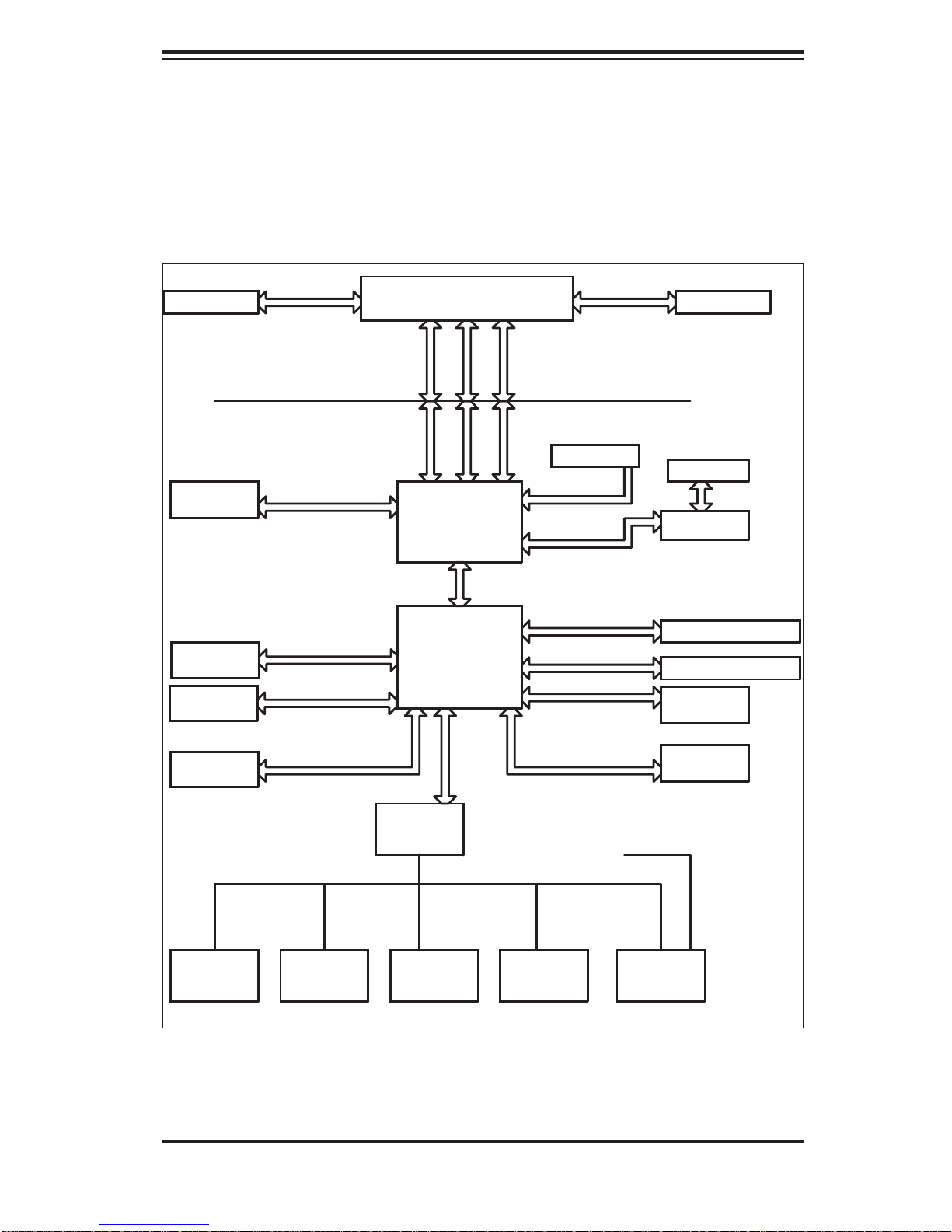
Figure 1-1 . Intel 3210 Chipset:
System Block Diagram
Note: This is a general block diagram. Please see Chapter 5 for details.
VRM 1 1
FSB: 1333/1066/800
DIMM_CHA
DIMM_CHB
PRI_ID
E
ATA
6xS
PORTS
US
B
PORTS_0~7
DDR2_667/800
UDMA/100
S-ATA/300
USB2.0/1.1
LGA775_PROCESSOR
ADDR
CTRL CTRL
ADDR
Intel 321 0
MC H
DMI
ICH9R
LP
C
DATADATA
PCIE_x 8
PCIE_x
PCIE_x 8
PCIE_x1
PCIE_x1
PCI_32_BUS
LP
C
CK505 CLK
1x
PCIX_64
8
PCI- X B US
PX H - V
GLAN2 82573L
GLAN1 82573V
ATI-ES100
FW
0
H
KB. FDD. SER.
MS.
W83627DH
LPC I/O
SER.2
G
IPMI I/F
1
PRINTER
IPMI
1-3
Page 12

SUPERSERVER 5015B-MT User's Manual
1-3 Server Chassis Features
The following is a general outline of the main features of the SC813MTQ-300C
chassis.
System Power
When confi gured as a SuperServer 5015B-MT, the SC813MTQ-300C chassis in-
cludes a single 300W power supply.
Serial ATA Subsystem
For the 5015B-MT, the SC813MT-300 chassis was designed to support four Serial
ATA har d drives , whic h are hot- swapp able uni ts.
Note: The operati ng system yo u use must h ave R AID su ppor t to e nable t he hotswap capability of the Serial ATA drives.
Control Panel
The SC813MTQ-300C's control panel provides important system monitoring and
control information. LEDs indicate power on, network activity, hard disk drive activity and system overheat conditions. The control panel also includes a main power
button and a system reset button. The front of the SC813MTQ-300C also includes
a COM port and two USB serial ports for easy access.
Rear I/O Panel
The SC813MTQ-300C is a 1U rackmount chassis. Its I/O panel provides one PCI
motherboard expansion slot, one COM port (another is internal), two USB ports,
a parallel (printer) port, PS/2 mouse and keyboard ports, a VGA port and two Gb
Ethernet ports.
Cooling System
The SC813MTQ-300C chassis has an innovative cooling design that features three
4-cm high-performance system cooling fans. Each of these fans plug into a chassis
fan header on the motherboard. An air shroud channels the airfl ow generated by
the fans to effi ciently cool the processor area of the system.
A fan speed control setting in BIOS allows fan speed to be determined by system
temperature [the recommended setting is 3-pin (Server)].
1-4
Page 13

Chapter 1: Introduction
1-4 Contacting Supermicro
Headquarters
Address: Super Micro Computer, Inc.
980 Rock Ave.
San Jose, CA 95131 U.S.A.
Tel: +1 (408) 503-8000
Fax: +1 (408) 503-8008
Email: [email protected] (General Information)
[email protected] (Technical Support)
Web Site: www.supermicro.com
Europe
Address: Super Micro Computer B.V.
Het Sterrenbeeld 28, 5215 ML
's-Hertogenbosch, The Netherlands
Tel: +31 (0) 73-6400390
Fax: +31 (0) 73-6416525
Email: [email protected] (General Information)
[email protected] (Technical Support)
[email protected] (Customer Support)
Asia-Pacifi c
Address: Super Micro Computer, Taiwan
4F, No. 232-1, Liancheng Rd.
Chung-Ho 235, Taipei County
Taiwan, R.O.C.
Tel: +886-(2) 8226-3990
Fax: +886-(2) 8226-3991
Web Site: www.supermicro.com.tw
Technical Support:
Email: [email protected]
Tel: 886-2-8228-1366, ext.132 or 139
1-5
Page 14

SUPERSERVER 5015B-MT User's Manual
Notes
1-6
Page 15

Chapter 2: Server Installation
Chapter 2
Server Installation
2-1 Overview
This chapter provides a quick setup checklist to get your SuperServer 5015B-MT
up and running. Following the steps in the order given should enable you to have
the system operational within a minimal amount of time. This quick setup assumes
that your 5015B-MT system has come to you with the processor and memory preinstalled. If your system is not already fully integrated with a motherboard, processor,
system memory etc., please turn to the chapter or section noted in each step for
details on installing specifi c components.
2-2 Unpacking the System
You should inspect the box the SuperServer 5015B-MT was shipped in and note
if it was damaged in any way. If the server itself shows damage, you should fi le a
damage claim with the carrier who delivered it.
Decide on a suitable location for the rack unit that will hold the SuperServer 5015BMT. It should be situated in a clean, dust-free area that is well ventilated. Avoid
areas where heat, electrical noise and electromagnetic fi elds are generated. You
will also need it placed near a grounded power outlet. Read the Rack and Server
Precautions in the next section.
2-3 Preparing for Setup
The box the SuperServer 5015B-MT was shipped in should include two sets of
rail assemblies, six rail mounting brackets and the mounting screws you will need
to install the system into the rack. Follow the steps in the order given to complete
the installation process in a minimal amount of time. Please read this section in
its entirety before you begin the installation procedure outlined in the sections that
follow.
Choosing a Setup Location
Leave enough clearance in front of the rack to enable you to open the front door •
completely (~25 inches) and approximately 30 inches of clearance in the back
of the rack to allow for suffi cient airfl ow and ease in servicing.This product is for
2-1
Page 16

SUPERSERVER 5015B-MT User's Manual
!
!
installation only in a Restricted Access Location (dedicated equipment rooms,
service closets and the like).
This product is not suitable for use with visual display work place devices
•
acccording to §2 of the the German Ordinance for Work with Visual Display
Units.
Warnings and Precautions!
Rack Precautions
Ensure that the leveling jacks on the bottom of the rack are fully extended to •
the fl oor with the full weight of the rack resting on them.
In single rack installation, stabilizers should be attached to the rack. In multiple
•
rack installations, the racks should be coupled together.
Always make sure the rack is stable before extending a component from the
•
rack.
You should extend only one component at a time - extending two or more si-
•
multaneously may cause the rack to become unstable.
Server Precautions
Review the electrical and general safety precautions in Chapter 4.•
Determine the placement of each component in the rack • before you install the
rails.
Install the heaviest server components on the bottom of the rack fi rst, and then
•
work up.
Use a regulating uninterruptible power supply (UPS) to protect the server from
•
power surges, voltage spikes and to keep your system operating in case of a
power failure.
Allow the hot plug SATA drives and power supply modules to cool before touch-
•
ing them.
Always keep the rack's front door and all panels and components on the servers
•
closed when not servicing to maintain proper cooling.
2-2
Page 17

Chapter 2: Server Installation
Rack Mounting Considerations
Ambient Operating Temperature
If installed in a closed or multi-unit rack assembly, the ambient operating temperature of the rack environment may be greater than the ambient temperature of the
room. Therefore, consideration should be given to installing the equipment in an
environment compatible with the manufacturer’s maximum rated ambient temperature (Tmra).
Reduced Airfl ow
Equipment should be mounted into a rack so that the amount of airfl ow required
for safe operation is not compromised.
Mechanical Loading
Equipment should be mounted into a rack so that a hazardous condition does not
arise due to uneven mechanical loading.
Circuit Overloading
Consideration should be given to the connection of the equipment to the power
supply circuitry and the effect that any possible overloading of circuits might have
on overcurrent protection and power supply wiring. Appropriate consideration of
equipment nameplate ratings should be used when addressing this concern.
Reliable Ground
A reliable ground must be maintained at all times. To ensure this, the rack itself
should be grounded. Particular attention should be given to power supply connections other than the direct connections to the branch circuit (i.e. the use of power
strips, etc.).
2-3
Page 18

SUPERSERVER 5015B-MT User's Manual
2-4 Installing the System into a Rack
This section provides information on installing the SuperServer 5015B-MT into a
rack unit with the rack rails provided. If the server has already been mounted into
a rack, you can skip ahead to Sections 2-5 and 2-6.
There are a variety of rack units on the market, which may mean the assembly
procedure will differ slightly. You should also refer to the installation instructions that
came with the rack unit you are using.
Identifying the Sections of the Rack Rails
You may have received rack rail hardware with the SuperServer 5015B-MT. (Two
front inner rails should already be attached to the chassis.) This hardware consists
of two rear inner rails that secure to the chassis, one on each side just behind the
preinstalled front inner rails. Note that these two rails are left/right specifi c.
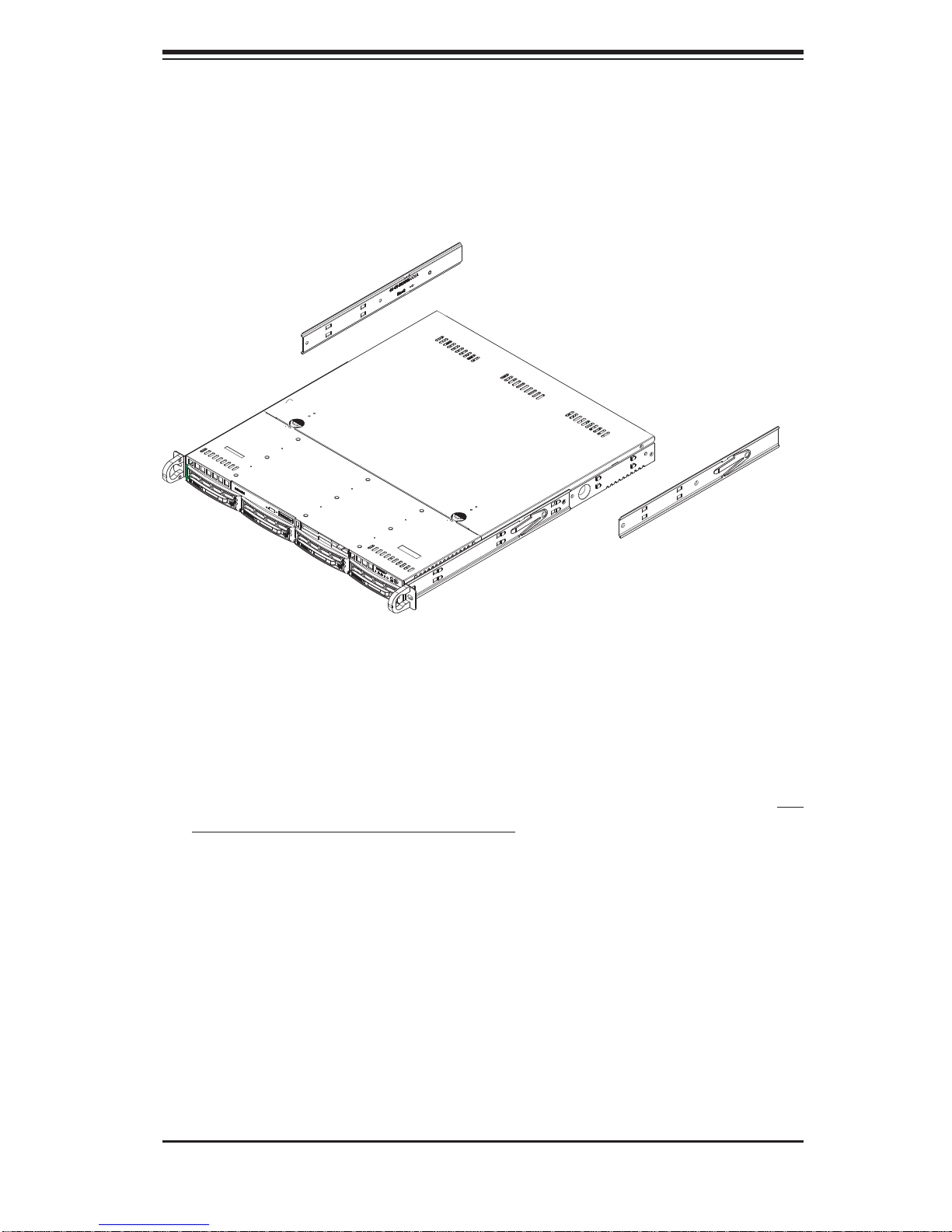
Installing the Rear Inner Rails
First, locate the right rear inner rail (the rail that will be used on the right side of
the chassis when you face the front of the chassis). Align the two square holes on
the rail against the hooks on the right side of the chassis. Securely attach the rail
to the chassis with M4 fl at head screws. Repeat these steps to install the left rear
inner rail to the left side of the chassis (see Figure 2-1). You will also need to attach
the rail brackets when installing into a telco rack.
Locking Tabs: Both chassis rails have a locking tab, which serves two functions.
The fi rst is to lock the server into place when installed and pushed fully into the
rack, which is its normal position. Secondly, these tabs also lock the server in place
when fully extended from the rack. This prevents the server from coming completely
out of the rack when you pull it out for servicing.
2-4
Page 19
Chapter 2: Server Installation
Figure 2-1. Installing Rear Inner Chassis Rails
Installing the Rack Rails
Determine where you want to place the SuperServer 5015B-MT in the rack (see
Rack and Server Precautions in Section 2-3). Position the chassis rail guides at the
desired location in the rack, keeping the sliding rail guide facing the inside of the
rack. Screw the assembly securely to the rack using the brackets provided. Attach
the other assembly to the other side of the rack, making sure that both are at the
exact same height and with the rail guides facing inward.
2-5
Page 20
SUPERSERVER 5015B-MT User's Manual
Installing the Server into the Rack
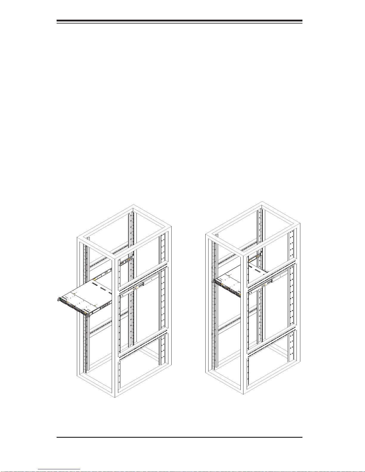
You should now have rails attached to both the chassis and the rack unit. The next
step is to install the server into the rack. Do this by lining up the rear of the chassis
rails with the front of the rack rails. Slide the chassis rails into the rack rails, keeping
the pressure even on both sides (you may have to depress the locking tabs when
inserting). See Figure 2-2.
When the server has been pushed completely into the rack, you should hear the
locking tabs "click".
Figure 2-2. Installing the Server into a Rack
(with optional front bezel shown)
2-6
Page 21
Chapter 2: Server Installation
Installing the Server into a Telco Rack
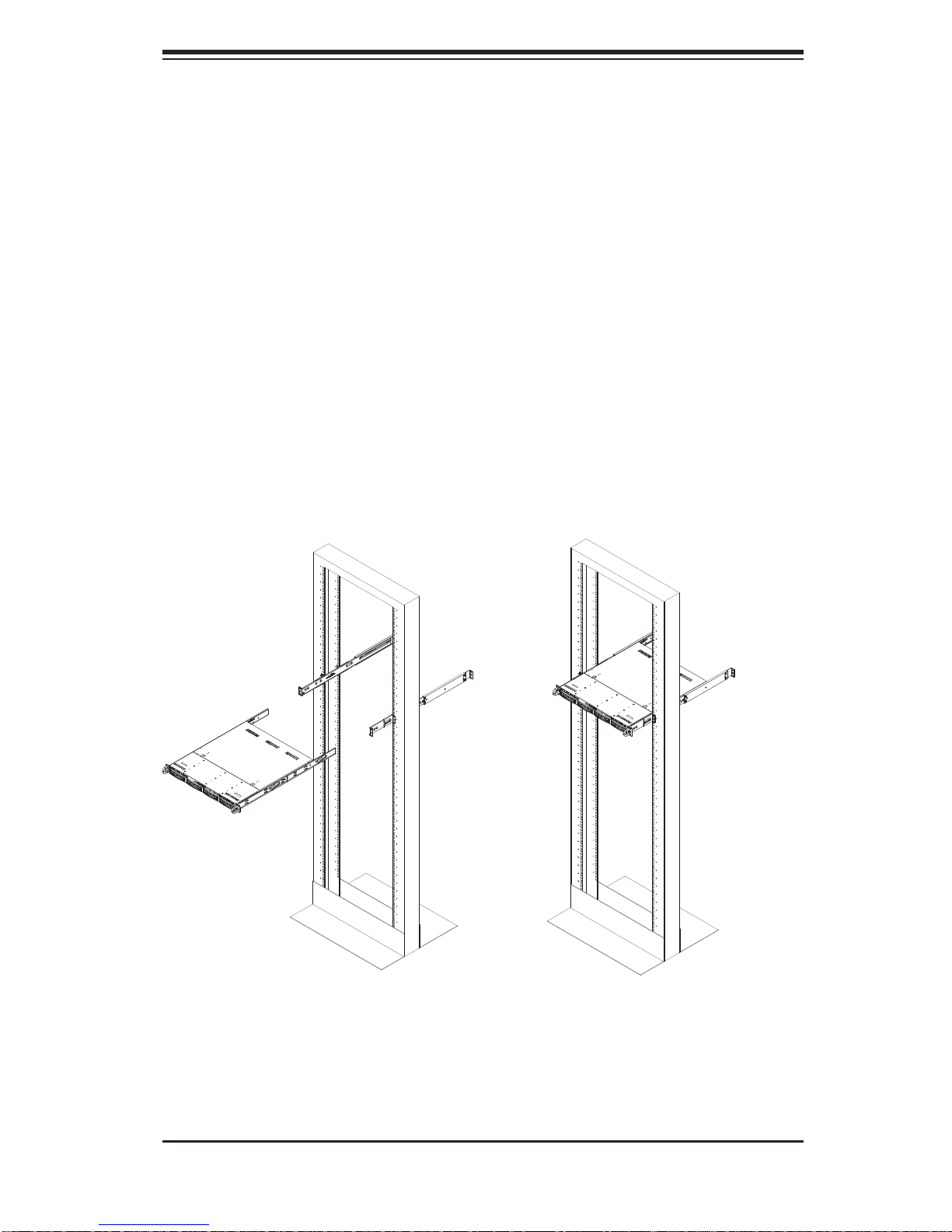
To install the SuperServer 5015B-MT into a Telco type rack, use two L-shaped
brackets on either side of the chassis (four total). First, determine how far the server
will extend out the front of the rack. Larger chassis should be positioned to balance
the weight between front and back. If a bezel is included on your server, remove
it. Then attach the two front brackets to each side of the chassis, then the two rear
brackets positioned with just enough space to accommodate the width of the rack.
Finish by sliding the chassis into the rack and tightening the brackets to the rack.
Figure 2-3. Installing the Server into a Telco Rack
(with optional front bezel shown)
2-7
Page 22

SUPERSERVER 5015B-MT User's Manual
2-5 Checking the Motherboard Setup
After you install the 5015B-MT in the rack, you will need to open the unit to make
sure the motherboard is properly installed and all the connections have been
made.
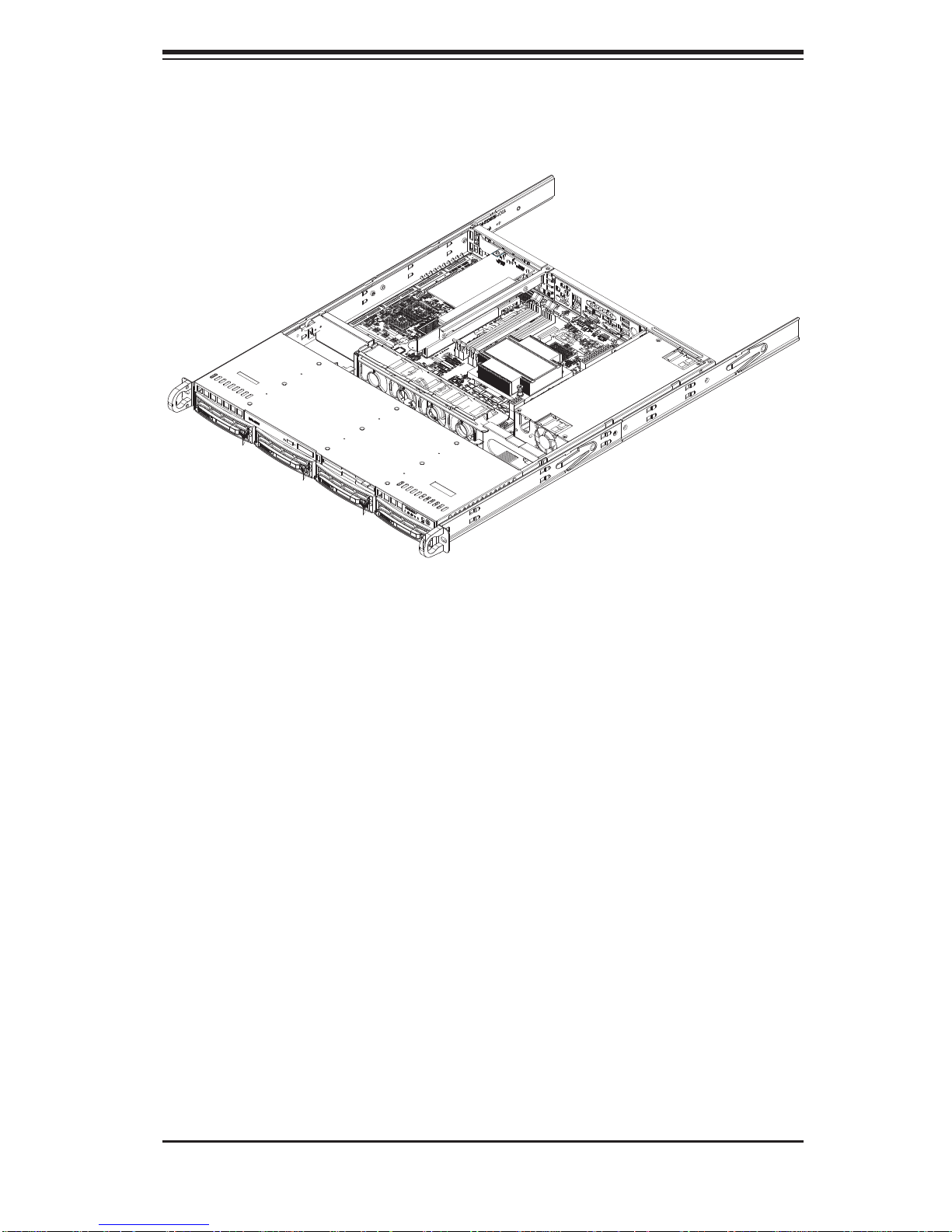
Accessing the Inside of the System
Grasp the two handles on either side and pull the unit straight out until it 1.
locks (you will hear a "click").
Depress the two buttons on the top of the chassis to release the top cover. 2.
There is a large rectangular recess in the middle front of the top cover to help
you push the cover away from you until it stops.
Lift the top cover from the chassis to gain full access to the inside of the 3.
server. See Figure 2-4.
Checking the Components
You may have the processor already installed into the system board. The 1.
processor should have its own heatsink attached. See Chapter 5 for instructions on processor installation.
Your 5015B-MT server system may have come with system memory already 2.
installed. Make sure all DIMMs are fully seated in their slots. For details on
adding system memory, refer to Chapter 5.
If desired, you can install an add-on card to the system. See Chapter 5 for 3.
details on installing a PCI add-on card.
Make sure all power and data cables are properly connected and not blocking 4.
the airfl ow. See Chapter 5 for details on cable connections.
2-8
Page 23
Chapter 2: Server Installation
Figure 2-4.
Accessing the Inside of the SuperServer 5015B-MT
2-6 Checking the Drive Bay Setup
Next, you should check to make sure the peripheral drives and the SATA drives
and SATA backplane have been properly installed and all essential connections
have been made.
Checking the Drives
All drives can be accessed from the front of the server. For servicing the 1.
CD-ROM drive, you will need to remove the top chassis cover. The SATA
disk drives can be installed and removed from the front of the chassis without
removing the top chassis cover.
Refer to Chapter 6 if you need to reinstall a CD-ROM drive to the system.2.
Depending upon your system's confi guration, your system may have one or 3.
more SATA drives already installed. If you need to install SATA drives, please
refer to the appropriate section in Chapter 6.
Checking the Airfl ow
Airfl ow is provided by four high-performance 4-cm input fans. The system 1.
component layout was carefully designed to promote suffi cient airfl ow through
the small 1U rackmount space.
2-9
Page 24

SUPERSERVER 5015B-MT User's Manual
Also note that all power and data cables have been routed in such a way that 2.
they do not block the airfl ow generated by the fans.
Providing Power
Plug the power cord from the power supply unit into a high-quality power strip 1.
that offers protection from electrical noise and power surges. It is recommended that you use an uninterruptible power supply (UPS).
Depress the power button on the front of the chassis to power up the system. 2.
2-10
Page 25

Chapter 3: System Interface
Chapter 3
System Interface
3-1 Overview
There are several LEDs on the control panel as well as others on the SATA drive
carriers to keep you constantly informed of the overall status of the system as well
as the activity and health of specifi c components. There are also two buttons on
the chassis control panel and an on/off switch on the power supply. This chapter
explains the meanings of all LED indicators and the appropriate response you may
need to take.
3-2 Control Panel Buttons
There are two push-buttons located on the front of the chassis: a reset button and
a power on/off button.
Reset
The reset switch reboots the system.
Power
This is the main power switch, which is used to apply or turn off the main system
power. Turning off system power with this button removes the main power but
keeps standby power supplied to the system.
3-1
Page 26

SUPERSERVER 5015B-MT User's Manual
3-3 Control Panel LEDs
The control panel located on the front of the SC813MTQ-300C chassis has fi ve
LEDs. These LEDs provide you with critical information related to different parts of
the system. This section explains what each LED indicates when illuminated and
any corrective action you may need to take.
Overheat/Fan Fail
When this LED fl ashes, it indicates a fan failure. When on continuously it indicates
an overheat condition, which may be caused by cables obstructing the airfl ow in
the system or the ambient room temperature being too warm. Check the routing of
the cables and make sure all fans are present and operating normally. You should
also check to make sure that the chassis covers are installed. Finally, verify that
the heatsinks are installed properly (see Chapter 5). This LED will remain fl ashing
or on as long as the indicated condition exists.
2
NIC2
Indicates network activity on GLAN2 when fl ashing.
1
NIC1
Indicates network activity on GLAN1 when fl ashing.
HDD
Channel activity for all HDDs. This light indicates CD-ROM and SATA drive activity
on the 5015B-MT when fl ashing.
3-2
Page 27

Chapter 3: System Interface
Power
Indicates power is being supplied to the system's power supply units. This LED
should normally be illuminated when the system is operating.
3-4 SATA Drive Carrier LEDs
Each SATA drive carrier has two LEDs.
Green:
• When illuminated, the green LED on the front of the SATA drive carrier
indicates drive activity. A connection to the SATA backplane enables this LED
to blink on and off when that particular drive is being accessed.
Red:
• The red LED indicates two states. When blinking, it indicates the drive
is rebuilding. When solid, it indicates a drive failure. If a SATA drive fails, you
should be notifi ed by your system management software. Please refer to Chapter
6 for instructions on replacing failed SATA drives.
3-3
Page 28

SUPERSERVER 5015B-MT User's Manual
Notes
3-4
Page 29
Chapter 4: System Safety
!
Chapter 4
System Safety
4-1 Electrical Safety Precautions
Basic electrical safety precautions should be followed to protect yourself from harm
and the SuperServer 5015B-MT from damage:
Be aware of the locations of the power on/off switch on the chassis as well
•
as the room's emergency power-off switch, disconnection switch or electrical
outlet. If an electrical accident occurs, you can then quickly remove power from
the system.
Do not work alone when working with high voltage components.
•
Power should always be disconnected from the system when removing or in-•
stalling main system components, such as the serverboard, memory modules
and fl oppy drive. When disconnecting power, you should fi rst power down the
system with the operating system fi rst and then unplug the power cords of all
the power supply units in the system.
When working around exposed electrical circuits, another person who is familiar
•
with the power-off controls should be nearby to switch off the power if necessary.
Use only one hand when working with powered-on electrical equipment. This
•
is to avoid making a complete circuit, which will cause electrical shock. Use
extreme caution when using metal tools, which can easily damage any electrical
components or circuit boards they come into contact with.
Do not use mats designed to decrease static electrical discharge as protection
•
from electrical shock. Instead, use rubber mats that have been specifi cally
designed as electrical insulators.
The power supply power cords must include a grounding plug and must be
•
plugged into grounded electrical outlets.
4-1
Page 30
SUPERSERVER 5015B-MT User's Manual
!
This product may be connected to an IT power system. In all cases, make sure •
that the unit is also reliably connected to Earth (ground).
Serverboard Battery:
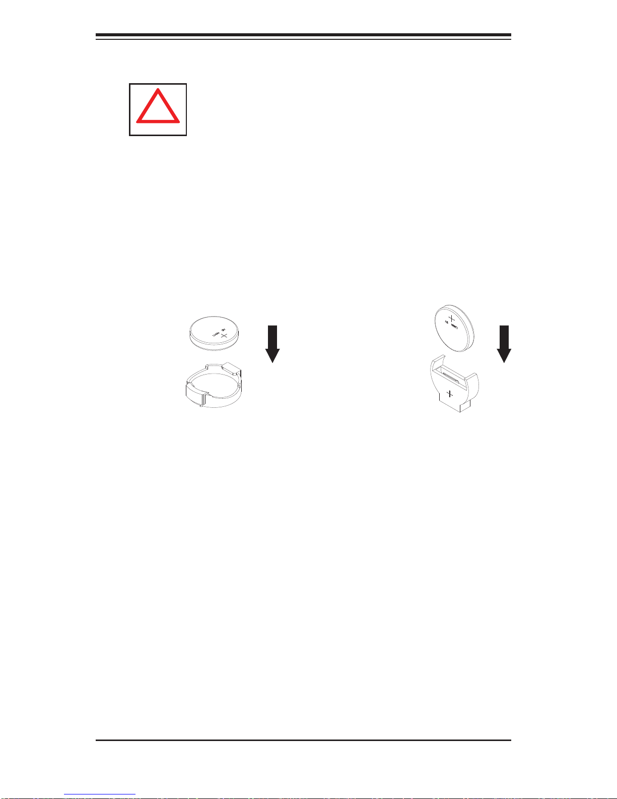
• CAUTION - There is a danger of explosion if the onboard
battery is installed upside down, which will reverse its polarites (see Figure
4-1). This battery must be replaced only with the same or an equivalent type
recommended by the manufacturer. Dispose of used batteries according to the
manufacturer's instructions.
CD-ROM Laser:
• CAUTION - this server may have come equipped with a CD-
ROM drive. To prevent direct exposure to the laser beam and hazardous radiation exposure, do not open the enclosure or use the unit in any unconventional
way.
Mainboard replaceable soldered-in fuses: Self-resetting PTC (Positive Tempera-
•
ture Coeffi cient) fuses on the mainboard must be replaced by trained service
technicians only. The new fuse must be the same or equivalent as the one
replaced. Contact technical support for details and support.
4-2 General Safety Precautions
Follow these rules to ensure general safety:
Keep the area around the 5015B-MT clean and free of clutter.
•
The 5015B-MT weighs approximately 38 lbs (~17.3 kg) when fully loaded. •
When lifting the system, two people at either end should lift slowly with their
feet spread out to distribute the weight. Always keep your back straight and lift
with your legs.
Place the chassis top cover and any system components that have been re-
•
moved away from the system or on a table so that they won't accidentally be
stepped on.
While working on the system, do not wear loose clothing such as neckties and
•
unbuttoned shirt sleeves, which can come into contact with electrical circuits or
be pulled into a cooling fan.
4-2
Page 31
Chapter 4: System Safety
!
Remove any jewelry or metal objects from your body, which are excellent metal •
conductors that can create short circuits and harm you if they come into contact
with printed circuit boards or areas where power is present.
After accessing the inside of the system, close the system back up and secure
•
it to the rack unit with the retention screws after ensuring that all connections
have been made.
4-3 ESD Precautions
Electrostatic Discharge (ESD) is generated by two objects with different electrical
charges coming into contact with each other. An electrical discharge is created to
neutralize this difference, which can damage electronic com ponents and printed
circuit boards. The following measures are generally suffi cient to neutralize this
difference before contact is made to protect your equipment from ESD:
Use a grounded wrist strap designed to prevent static discharge.
•
Keep all components and printed circuit boards (PCBs) in their antistatic bags •
until ready for use.
Touch a grounded metal object before removing the board from the antistatic
•
bag.
Do not let components or PCBs come into contact with your clothing, which may
•
retain a charge even if you are wearing a wrist strap.
Handle a board by its edges only; do not touch its components, peripheral chips,
•
memory modules or contacts.
When handling chips or modules, avoid touching their pins.
•
Put the serverboard and peripherals back into their antistatic bags when not •
in use.
For grounding purposes, make sure your computer chassis provides excellent
•
conductivity between the power supply, the case, the mounting fasteners and
the serverboard.
4-3
Page 32
SUPERSERVER 5015B-MT User's Manual
!
4-4 Operating Precautions
Care must be taken to assure that the chassis cover is in place when the 5015B-MT
is operating to assure proper cooling. Out of warranty damage to the system can
occur if this practice is not strictly followed.
Figure 4-1. Installing the Onboard Battery
LITHIUM BATTERY
LITHIUM BATTERY
OR
BATTERY HOLDER BATTERY HOLDER
4-4
Page 33

Chapter 5: Advanced Serverboard Setup
Chapter 5
Advanced Serverboard Setup
This chapter covers the steps required to install the X7SBi serverboard into the chassis, connect the data and power cables and install add-on cards. All serverboard
jumpers and connections are also described. A layout and quick reference chart
are included in this chapter for your reference. Remember to completely close the
chassis when you have fi nished working with the serverboard to better cool and
protect the system.
5-1 Handling the Serverboard
Electrostatic Discharge (ESD) can damage electronic com ponents. T o prevent damage to any printed circuit boards (PCBs), it is important to handle them very carefully
(see previous chapter). To prevent the serverboard from bending, keep one hand
under the center of the board to support it when handling. The following measures
are generally suffi cient to protect your equipment from electric static discharge.
Precautions
Use a grounded wrist strap designed to prevent Electrostatic Discharge •
(ESD).
Touch a grounded metal object before removing any board from its antistatic
•
bag.
Handle a board by its edges only; do not touch its components, peripheral chips,
•
memory modules or gold contacts.
When handling chips or modules, avoid touching their pins.
•
Put the serverboard, add-on cards and peripherals back into their antistatic •
bags when not in use.
For grounding purposes, make sure your computer chassis provides excellent
•
conductivity between the power supply, the case, the mounting fasteners and
the serverboard.
5-1
Page 34

SUPERSERVER 5015B-MT User's Manual
Unpacking
The serverboard is shipped in antistatic packaging to avoid electrical static discharge. When unpacking the board, make sure the person handling it is static
protected.
5-2 Serverboard Installation
This section explains the fi rst step of physically mounting the X7SBi into the
SC813MTQ-300C chassis. Following the steps in the order given will eliminate
the most common problems encountered in such an installation. To remove the
serverboard, follow the procedure in reverse order.
Installing to the Chassis
Access the inside of the system by removing the screws from the back lip of 1.
the top cover of the chassis, then pull the cover off.
The X7SBi requires a chassis big enough to support a 12" x 9.6" serverboard, 2.
such as Supermicro's SC813MTQ-300C.
Make sure that the I/O ports on the serverboard align properly with their 3.
respective holes in the I/O shield at the back of the chassis.
Carefully mount the serverboard to the serverboard tray by aligning the board 4.
holes with the raised metal standoffs that are visible in the chassis.
Insert screws into all the mounting holes on your serverboard that line up 5.
with the standoffs and tighten until snug (if you screw them in too tight, you
might strip the threads). Metal screws provide an electrical contact to the
serverboard ground to provide a continuous ground for the system.
Finish by replacing the top cover of the chassis.6.
5-2
Page 35

Chapter 5: Advanced Serverboard Setup
5-3 Connecting Cables
Now that the serverboard is installed, the next step is to connect the cables to the
board. These include the data cables for the peripherals and control panel and the
power cables.
Connecting Data Cables
The cables used to transfer data from the peripheral devices have been carefully
routed to prevent them from blocking the fl ow of cooling air that moves through
the system from front to back. If you need to disconnect any of these cables, you
should take care to keep them routed as they were originally after reconnecting
them (make sure the red wires connect to the pin 1 locations). The following data
cables (with their locations noted) should be connected. (See the layout on page
5-11 for connector locations.)
Control Panel cable (JF1)
•
DVD-ROM drive cable (IDE)•
COM Port cable (COM2)•
Front USB port cable (USB6/7)•
SATA drive data cables (SATA0 ~ SATA3)•
Important! Make sure the the cables do not come into contact with the fans.
Connecting Power Cables
The X7SBi has a 24-pin primary power supply connector (JPW1) for connection
to the ATX power supply. In addition, there is an 8-pin processor power connector
(JPW2) that must be connected to your power supply. See Section 5-9 for power
connector pin defi nitions.
Connecting the Control Panel
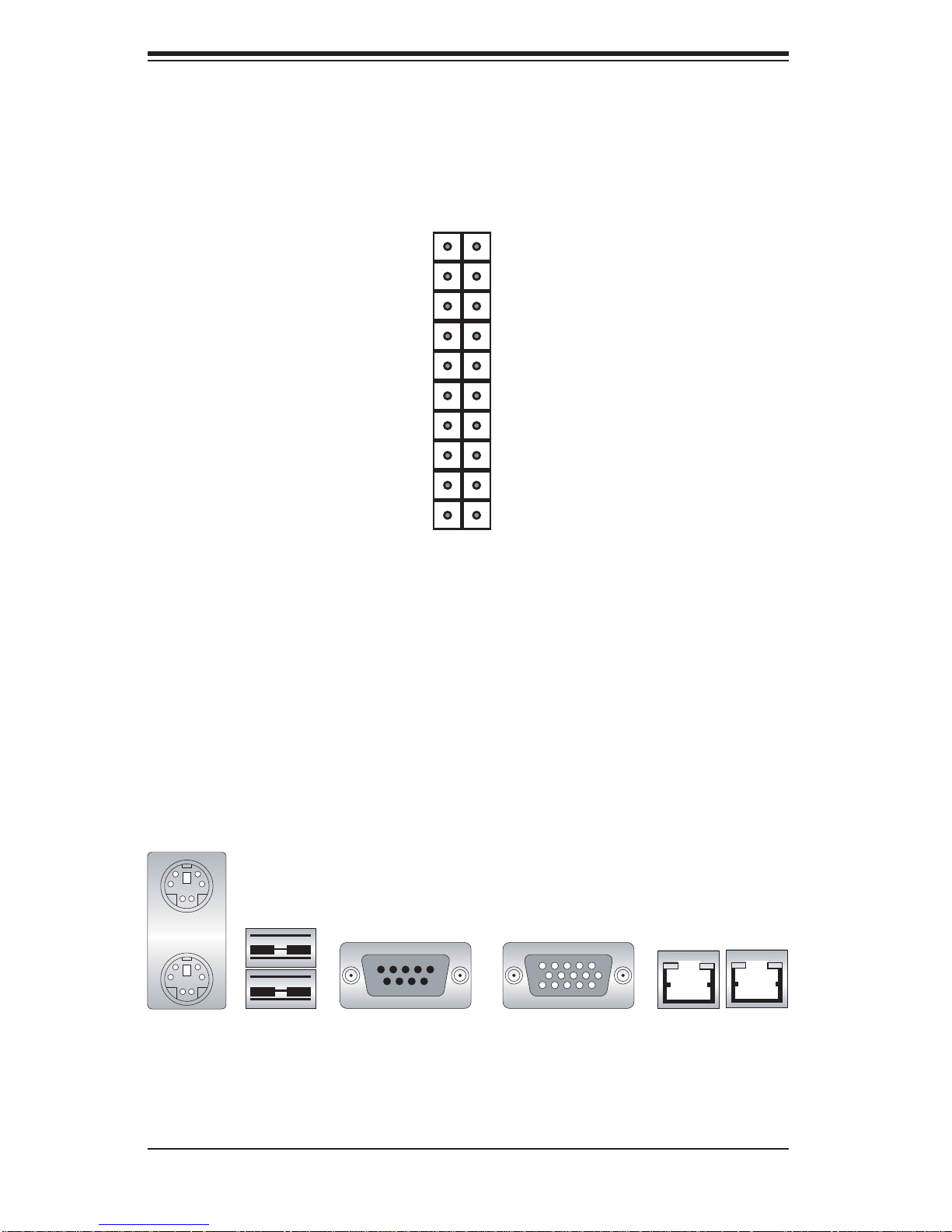
JF1 contains header pins for various front control panel connectors. See Figure 5-1
for the pin locations of the various front control panel buttons and LED indicators.
All JF1 wires have been bundled into a single cable to simplify this connection. Make
sure the red wire plugs into pin 1 as marked on the board. The other end connects
to the Control Panel PCB board, located just behind the system status LEDs on
the chassis. See Chapter 5 for details and pin descriptions.
5-3
Page 36
SUPERSERVER 5015B-MT User's Manual
Figure 5-1. Control Panel Header Pins
20 19
Ground
NMI
x (Key)
Power On LED
HDD LED
NIC1 LED
NIC2 LED
OH/Fan Fail LED
Power Fail LED
Ground
Ground
2 1
x (Key)
Vcc
Vcc
Vcc
Vcc
Vcc
Vcc
Reset (Button)
Power (Button)
5-4 I/O Ports
The I/O ports are color coded in conformance with the PC 99 specifi cation. See
Figure 5-2 below for the colors and locations of the various I/O ports.
Mouse (Green)
USB0/1 Ports
Keyboard
(Purple)
Figure 5-2. I/O Ports
COM1 Port
(Turquoise)
LAN1/2 Ports
VGA Port
(Blue)
5-4
Page 37
Chapter 5: Advanced Serverboard Setup
!
5-5 Installing the Processors and Heat Sinks
Avoid placing direct pressure to the top of the processor package. Always
remove the power cord fi rst before adding, removing or changing any
hardware components.
Notes: Always connect the power cord last and remove it before adding, removing or changing any components. Make sure to install the processor into the CPU
socket before you install the CPU heat sink.
Intel's boxed Xeon CPU package contains the CPU fan and heat sink assembly. If
you buy the CPUs separately, use only Intel-certifi ed heat sinks and fans.
Inspect the Xeon 3200/3000 CPU socket and make sure that the CPU plastic cap
is in place and none of the socket pins are bent. Otherwise, contact the retailer
immediately.
All graphics shown in this manual are for reference only. The components that
came with your serverboard may or may not look exactly the same as the pictures
shown in this manual.
Installing the CPU
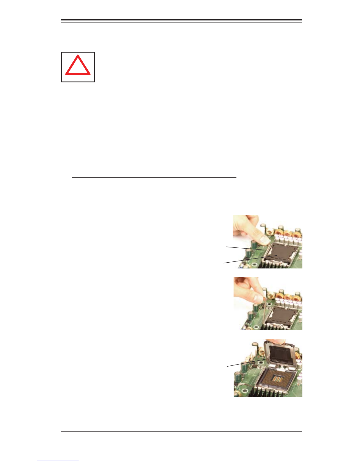
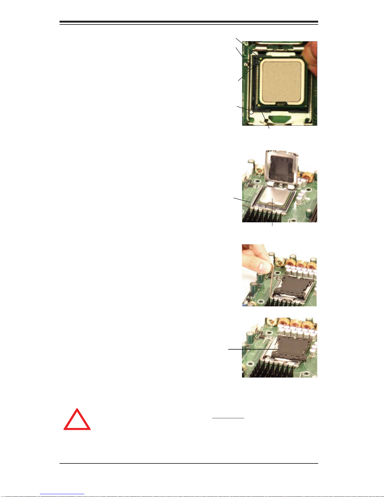
A black PnP cap is attached to 1.
the load plate to protect the CPU
socket. Press the load lever down
and away from the retention clasp
to release the load plate from its
locked position.
Gently lift the load lever to release 2.
the load plate.
Use your thumb and your index 3.
fi nger to hold the CPU at opposite
sides.
Align pin1 of the CPU (the corner 4.
marked with a triangle) with the
notched corner of the CPU socket.
Load lever
PnP cap
Load plate released
Find the corner of the CPU that 5.
has a semi-circle cutout below a
gold dot (CPU key). This corner
should be aligned with the cutout
on the socket (socket key).
5-5
Page 38
SUPERSERVER 5015B-MT User's Manual
!
Once aligned, carefully lower 1.
the CPU straight down into the
socket. Do not drop the CPU on
the socket, do not move the CPU
horizontally or vertically and do not
rub the CPU against any surface
or any of the contacts, which may
damage the CPU and/or contacts.
With the CPU in the socket, in-2.
spect the four corners of the CPU
to make sure that it is properly
installed.
Use your thumb to gently push the 3.
load lever down until it snaps into
the retention clasp.
If the CPU is properly installed 4.
into the socket, the PnP cap will
be automatically released from the
load plate when the lever locks.
Remove the cap. Repeat steps to
install a second CPU if desired.
Gold dot
Socket key
CPU key
Notched corner
CPU pin 1
Load lever
CPU installed in socket
Warning! Keep the plastic PnP cap.
The serverboard must be shipped with
the PnP cap properly installed to protect
the CPU socket. Shipment without the
Warning! Make sure you lift the lever completely when installing the CPU;
otherwise, damage to the socket or CPU may occur.
PnP cap released
from load plate
5-6
Page 39
Installing the CPU Heat Sink
!
Do not apply any thermal grease to the 1.
heat sink or the CPU die; the required
amount has already been applied.
Chapter 5: Advanced Serverboard Setup
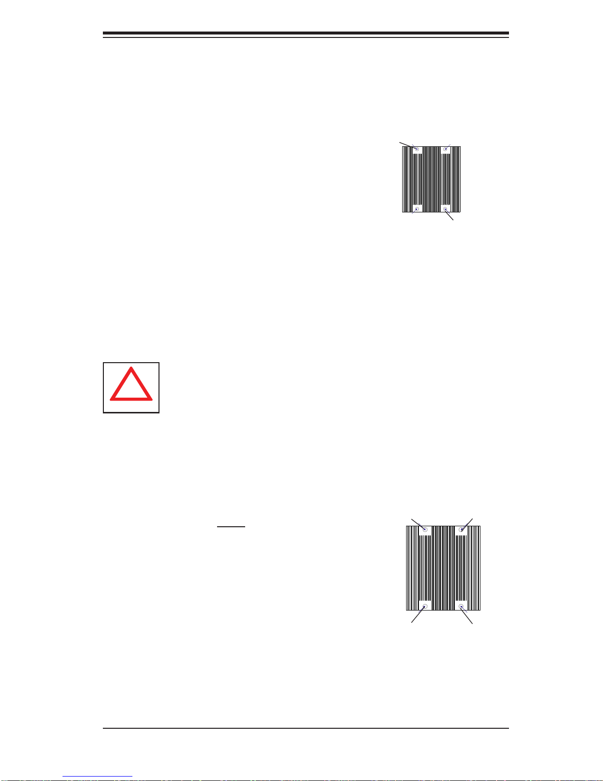
Place the heatsink on top of the CPU so 2.
that the four mounting holes are aligned
with those on the retention mechanism.
Screw in two diagonal screws (i.e. the #1 3.
and the #2 screws) until just snug (do not
over-tighten the screws, which may damage the CPU.)
Finish the installation by fully tightening all 4.
four screws.
Uninstalling the Heat Sink
Warning: We do not recommend removing the CPU or the heat sink.
However, if you do need to uninstall the heat sink, please follow these
instructions to avoid damaging the CPU or the CPU socket.
Screw #1
Screw #2
Unscrew and remove the heat sink 1.
screws in the sequence shown in the
picture on the right.
Hold the heat sink as shown in the picture 2.
on the right and gently wriggle to loosen
it from the CPU. (Do not use excessive
force when doing this!)
Once the heat sink is loosened, remove it 3.
from the CPU socket.
Clean the surface of the CPU and the 4.
heat sink to get rid of the old thermal
grease. Reapply the proper amount of
thermal grease before you re-install the
heat sink.
Screw #1
Screw #4
Screw #3
Screw #2
5-7
Page 40

SUPERSERVER 5015B-MT User's Manual
!
5-6 Installing Memory
CAUTION! Exercise extreme care when installing or removing DIMM
modules to prevent any possible damage.
Memory Support
The X7SBi supports dual or single channel, ECC/Non-ECC unbuffered DDR2800 /667 SDR AM. Bot h interleaved an d non-inter leaved memor y are suppo rted,
so you may populate any number of DIMM slots. (Populating DIMM#1A/DIMM#2A
and/or DI M M #1B/D IM M # 2 B wi th me mo r y mo dul es of t he sa me si ze and t y pe wi ll
result in two-way interleaved memory, which is faster than single channel, noninterleaved memor y.) Note that when ECC memory is used, it may take 25 -40
seco nds for t he VGA to disp lay.)
Installing Memory Modules
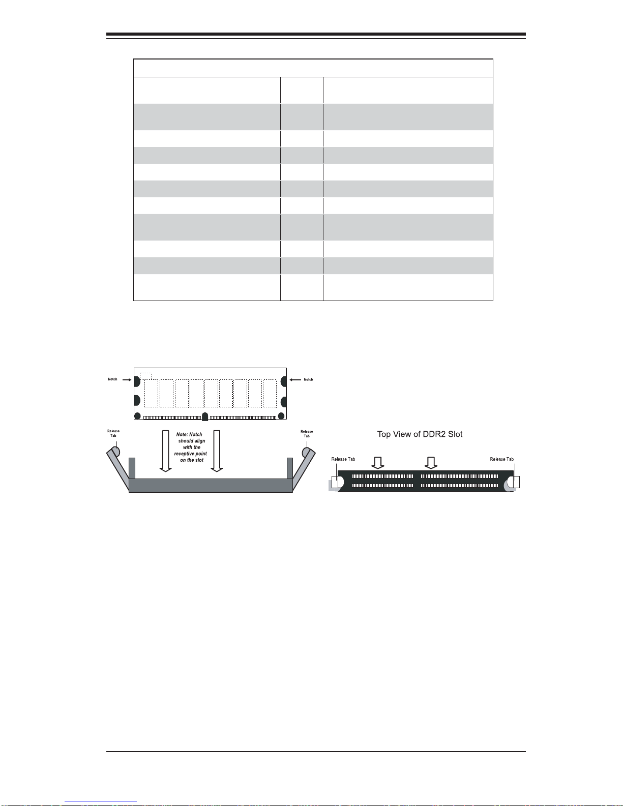
Inser t eac h DDR 2 mem or y modu le ver tic ally into i ts slot , starting with DIMM 1.
#1A. Pay attentio n to the notc h alon g the bot tom of th e modul e to prevent
inserting the module incorrect ly.
Gently press down on the DIMM module until it snaps into place in the slot. 2.
Repeat for all modules. (See suppo rt in form ation b elow.)
To enhance memory performance, install pairs of memory modules of the 3.
same type and of the same, beginning with DIMM #1A and DIMM #2A, then
DIMM #1B and DIMM #2B.
Notes
Due to a chipset limitation, 8GB of memory can only be supported by the following
operating systems:
32-Bit: Windows 2000 Advanced Server, Windows Server 2003 Enterprise Edi-
•
tion;
64-Bit: Windows Server 2003 Standard x64 Edition, Windows XP Professional
•
x64 Edition, Windows Server 2003 Enterprise x64 Edition
Some old-versions of DDR2-667 may not match Intel's On-Die Temperature requirement and will automatically be downgraded to run at 533 MHz. If this occurs, contact
your memory vendor to check the ODT value.
Due to memory allocation to system devices, memory remaining available for
operational use will be reduced when 4 GB of RAM is used. The reduction in
memory availability is disproportional. (Refer to the Memory Availability Table
below fo r detai ls.)
5-8
Page 41
Chapter 5: Advanced Serverboard Setup
Possible System Memory Allocation & Availability
System Device Size Physical Memory Remaining
Firmware Hub fl ash memory (System
BIOS)
Local APIC 4 KB 3.99
Area Reserved for the chipset 2 MB 3.99
I/O APIC (4 Kbytes) 4 KB 3.99
PCI Enumeration Area 1 256 MB 3.76
PCI Express (256 MB) 256 MB 3.51
PCI Enumeration Area 2 (if needed)
-Aligned on 256-MB boundaryVGA Memory 16 MB 2.85
TSEG 1 MB 2.84
Memory available to System BIOS &
OS applications
1 MB 3.99
512 MB 3.01
(4 GB Total System Memory)
2.84
Figure 5-3. DIMM Installation
To Install: Insert mod-
DDR2
ule vertically and press
down until it snaps into
place. Pay attention to
the bottom notches.
To Remove: Use your
thumbs to gently push
each release tab outward to free the DIMM
from the slot.
5-7 Adding PCI Expansion Cards
The SC813MTQ-300C chassis can accommodate one full-size PCI-Express, PCI-X
or PCI expansion card with the use of a riser card.
Installing an Add-on Card
After powering down the system, remove the PCI slot shield.1.
Fully seat the riser card into the slot, pushing down with your thumbs evenly 2.
on both sides of the card. Seat the expansion card into the riser card.
Finish by using a screw to secure the top of the card shield to the chassis. 3.
The PCI slot shield protects the serverboard and its components from EMI
and aid in proper ventilation, so make sure it is always in place.
5-9
Page 42
SUPERSERVER 5015B-MT User's Manual
5-8 Serverboard Details
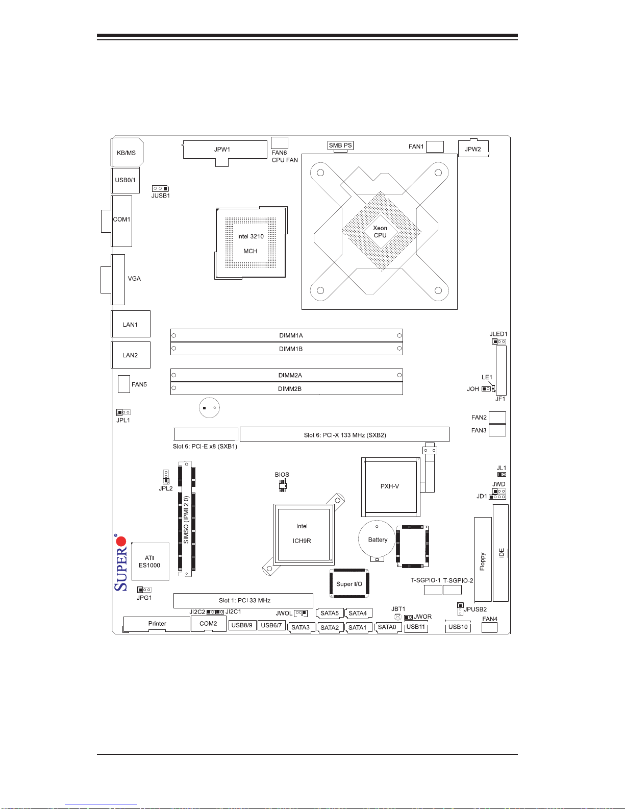
Figure 5-4. X7SBi Layout
(not drawn to scale)
X7SBi
200
Notes
Jumpers not indicated are for testing purposes only.
Slot 6 PCI -Exp. x 8 and the PCI-X sl ots are speci ally designe d for Supermi cro's
propr ietar y r iser c ards on ly.
5-10
Page 43

Chapter 5: Advanced Serverboard Setup
X7SBi Quick Reference
Jumper Description Default Setting
JBT1 CMOS Clear (See Section 5-10)
2
JI
C1/JI2C2 SMB to PCI Slots Open (Disabled)
JPG1 VGA Enable/Disable Pins 1-2 (Enabled)
JPL1/JPL2 LAN1/2 Enable/Disable Pins 1-2 (Enabled)
JPUSB1 Back panel U SB Wake- Up Pins 1-2 (Enable d)
JPUSB2 Front Acc ess U SB Wake- Up Pins 2-3 (D isab led)
JWD Watch Dog Pins 1-2 (Reset)
Connector Description
COM1/COM2 COM1/COM2 Serial Port/Header
FAN 1-6 Chassis/CPU Fan Headers
Floppy Floppy Disk Drive Connector
F/P USB6/7, F/P USB8/9 Front Panel Ac ces sible U SB He aders
IDE IDE HDD Connector
JD1 Speaker Header
JF1 Front Panel Connector
JL1 Chassis Intrusion Header
JLED Power LED Header
JOH Overheat Warning Header
JPW1 24-pin Main ATX Power Connector
JPW2 +12V 8-pin Secondary Power Connector
JWOL/JWOR Wake-On-LAN Header/Wake-On-Ring Header
LAN1/2 Gigabit Ethernet (RJ45) Ports
Printer Parallel (Printer) Port
SATA0 ~ SATA5 SATA Ports
SIMSO SIMSO IPMI 2.0 Socket
SMB_PS Power Supply SMBus Connector
T-SGPIO-1/T-SGPIO-2 Serial General Purpose Input/Output Headers
USB0/1 Universal Serial Bus (USB) Ports
USB10, USB11 Onboard Universal Serial Bus (USB) Ports
LED Description
LE1 Onboa rd Stan dby PWR war ning LE D Indic ator
5-11
Page 44
SUPERSERVER 5015B-MT User's Manual
5-9 Connector Defi nitions
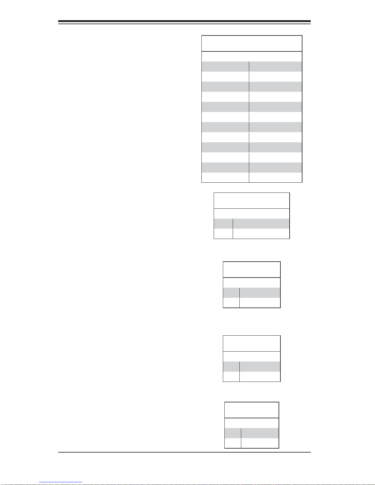
Main ATX Power Supply
Connector
The primary power supply connector
(JPW1) meets the SSI (Superset ATX)
24-pin specifi cation. Refer to the table
on the right for the pin defi nitions of
the ATX 24-pin power connector. You
must also connect the 8-pin (JPW2/
JPW3) processor power connectors to
your power supply (see below).
Secondary Power Connector
JPW2 must also be connected to the
power supply. See the table on the
right for pin defi nitions.
ATX Power 24-pin Connector
Pin Defi nitions (JPW1)
Pin# Defi nition Pin # Defi nition
13 +3.3V 1 +3.3V
14 -12V 2 +3.3V
15 COM 3 COM
16 PS_ON 4 +5V
17 COM 5 COM
18 COM 6 +5V
19 COM 7 COM
20 Res (NC) 8 PWR_OK
21 +5V 9 5VSB
22 +5V 10 +12V
23 +5V 11 +12V
24 COM 12 +3.3V
+12V 4-pin Power
Pin Defi nitions (JPW2)
Pins Defi nition
1 - 4 Ground
5 - 8 +12V
Required Connection
PW_ON Connector
The PW_ON connector is on pins 1
and 2 of JF1. This header should be
connected to the chassis power button. See the table on the right for pin
defi nitions.
Reset Connector
The reset connector is located on pins
3 and 4 of JF1 and attaches to the
reset switch on the computer chassis. See the table on the right for pin
defi nitions.
Power Fail LED
The Power Fail LED connection is
locate d on pins 5 and 6 of JF1. Refer to the table on the right for pin
defi nitions.
Power Button
Pin Defi nitions (JF1)
Pin# Defi nition
1 PW_ON
2 Ground
Reset Button
Pin Defi nitions (JF1)
Pin# Defi nition
3 Reset
4 Ground
PWR Fail LED
Pin Defi nitions (JF1)
Pin# Defi nition
5 Vcc
6 Ground
5-12
Page 45
Chapter 5: Advanced Serverboard Setup
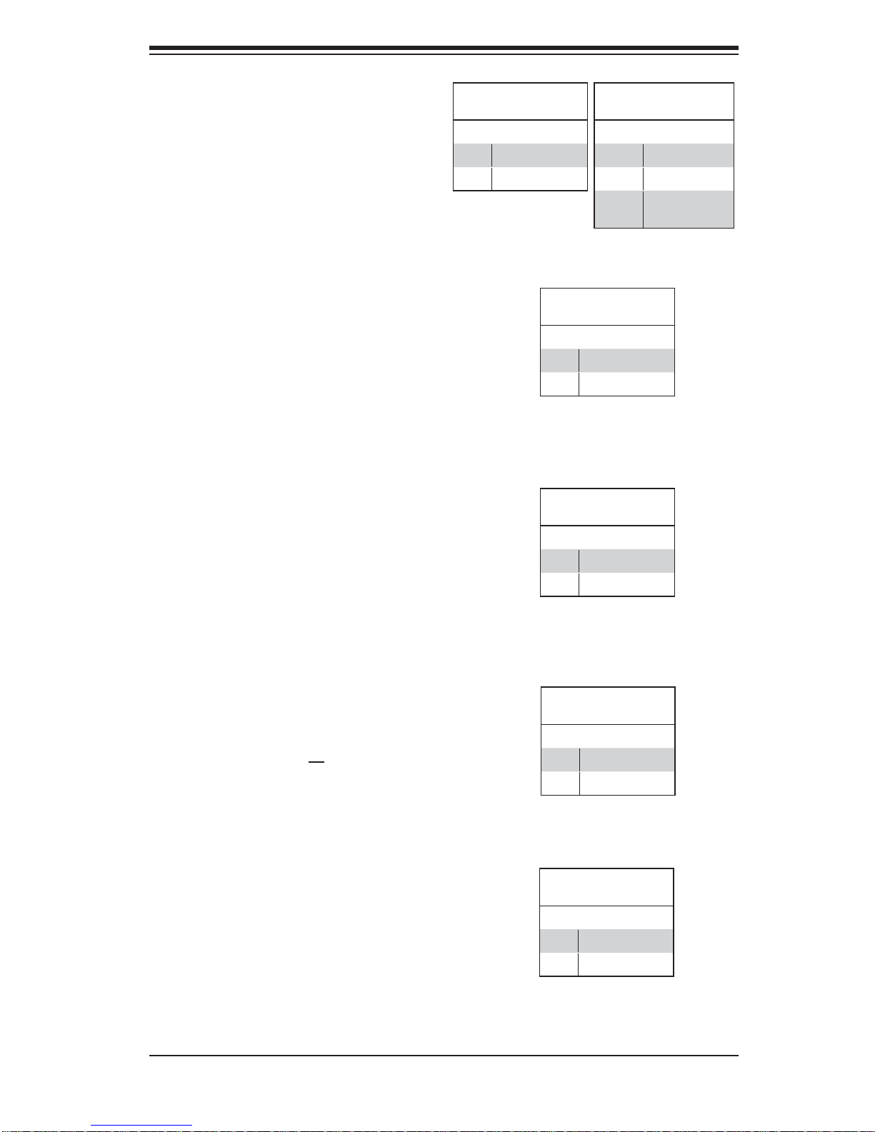
Overheat/Fan Fail LED (OH)
Connect an LED to the OH connection
on pins 7 and 8 of JF1 to provide advanced warning of chassis overheating. Refer to the table on the right for
pin defi nitions.
NIC2 (JLAN2) LED
The LED connections for JLAN2 are
on pins 9 and 10 of JF1. Attach an
LED cable to display network activity. See the table on the right for pin
defi nitions.
NIC1 (JLAN1) LED
The LED connections for JLAN1 are
on pins 11 and 12 of JF1. Attach an
LED cable to display network activity. See the table on the right for pin
defi nitions.
OH/Fan Fail LED
Pin Defi nitions (JF1)
Pin# Defi nition
7 Vcc
8 Ground
Pin Defi nitions (JF1)
Pin# Defi nition
9 Vcc
10 Ground
Pin Defi nitions (JF1)
Pin# Defi nition
11 Vcc
12 Ground
OH/Fan Fail Indicator
Status
State Defi nition
Off Normal
On Overheat
Flash-
ing
NIC2 LED
NIC1 LED
Fan Fail
HDD LED
The HDD LED connection is located
on pins 13 and 14 of JF1. This LED
is used to display all IDE and SATA
activity. See the table on the right for
pin defi nitions.
Power On LED
The Power On LED connector is located on pins 15 and 16 of JF1 (use
JLED for a 3-pin connector). This
connection is used to provide LED
indication of power being supplied to
the system. See the table on the right
for pin defi nitions.
5-13
HDD LED
Pin Defi nitions (JF1)
Pin# Defi nition
13 Vcc
14 HD Active
Power LED
Pin Defi nitions (JF1)
Pin# Defi nition
15 5V Stby
16 Control
Page 46
SUPERSERVER 5015B-MT User's Manual
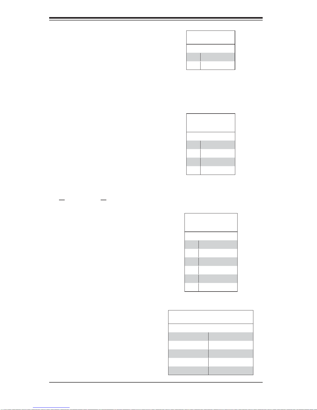
NMI Button
The non-maskable interrupt button
header is located on pins 19 and 20
of JF1. Refer to the table on the right
for pin defi nitions.
Fan Headers
There are six fan headers on the
serverboard, all of which are 4-pin
fans. However, pins 1-3 of the fan
headers are backward compatible
with the traditional 3-pin fans. See
the table on the right for pin defi ni-
tions. The onboard fan speeds are
controlled by Thermal Management
(via Hardwa re Monitori ng) under t he
Advanced Section in the BIOS. The
default is disabled. When using Thermal Management setting, please use
all 3 -pin f ans or al l 4- pin fa ns.
NMI Button
Pin Defi nitions (JF1)
Pin# Defi nition
19 Control
20 Ground
Fan Header
Pin Defi nitions
(FAN1-8)
Pin# Defi nition
1 Ground (Black)
2 +12V (Red)
3 Tachometer
4 PWM Control
Note: Fan 6 is the header for
the CPU heat sink fan.
ATX PS/2 Keyboard and PS/2
Mouse Ports
The ATX PS/2 keyboard and the PS/2
mouse are located beside the USB0/1
ports. The mouse port is above the
keyboard port. See the table on the
right for pin defi nitions.
Serial Ports
Two serial ports are included on the
serverboard. COM1 is a backpanel
port and COM2 is a header located
beside the printer port. See the table
on the right for pin defi nitions.
PS/2 Keyboard and
Mouse Port Pin
Defi nitions (J28)
Pin# Defi nition
1 Data
2NC
3 Ground
4 VCC
5 Clock
6NC
Serial Port Pin Defi nitions
(COM1/COM2)
Pin # Defi nition Pin # Defi nition
1 DCD 6 DSR
2 RXD 7 RTS
3 TXD 8 CTS
4 DTR 9 RI
5 Ground 10 NC
5-14
Page 47
Chassis Intrusion
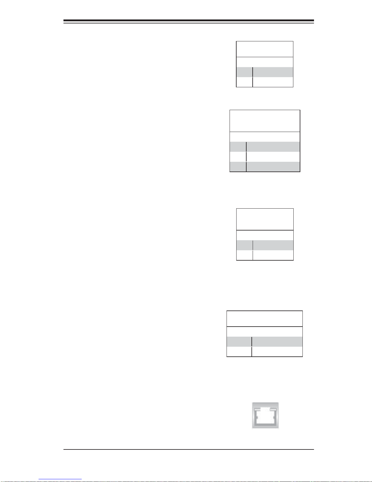
The Chassis Intrusion header is designated JL1. Attach an appropriate
cable from the chassis to inform you
of a chassis intrusion when the chassis is opened
Wake-On-LAN
The Wake-On-LAN header is designated JWOL on the serverboard. See
the table on the right for pin defi ni-
tions. You must also have a LAN card
with a Wake-On-LAN connector and
cable to use this feature.
Chapter 5: Advanced Serverboard Setup
Chassis Intrusion
Pin Defi nitions (JL1)
Pin# Defi nition
1 Intrusion Input
2 Ground
Wake-On-LAN
Pin Defi nitions
(JWOL)
Pin# Defi nition
1 +5V Standby
2 Ground
3 Wake-up
Wake-On-Ring
The Wake-On-Ring header is designated JWOR. This function allows your
computer to receive and be "awakened" by an incoming call when in the
suspend state. See the table on the
right for pin defi nitions. You must also
have a WOR card and cable to use
this feature.
External Speaker/Internal Buzzer
On the JD1 header, pins 1-4 are for an
external speaker an d pins 3 -4 are for the
internal speaker . If y ou wish to use an ex ternal speaker, connect it to pins 1-4 to. If
you wish to use the onboard speaker, you
should c lose p ins 3 - 4 wit h a jumper.
Wake-On-Ring
Pin Defi nitions
(JWOR)
Pin# Defi nition
1 Ground (Black)
2 Wake-up
Speaker Connector
(JD1)
Pin Setting Defi nition
Pins 3-4 Internal Speaker
Pins 1-4 External Speaker
LAN1/2 (Ethernet Ports)
Two Ethernet ports (designated LAN1
and LAN2) are located beside the VGA
port on the I/O backplane. These ports
accept RJ45 type cables.
5-15
Page 48
SUPERSERVER 5015B-MT User's Manual
Universal Serial Bus (USB)
There are two Universal Serial Bus
ports located on the I/O panel and four
additional USB headers located on
the serverboard. The headers can be
used to provide front side USB access
(cables not included). See the table on
the right for pin defi nitions.
SGPIO Headers
The SGPIO (Serial General Purpose
Input/Output) headers are used to
communicate with a system-monitoring chip on the backplane. See the
table on the right for pin defi nitions.
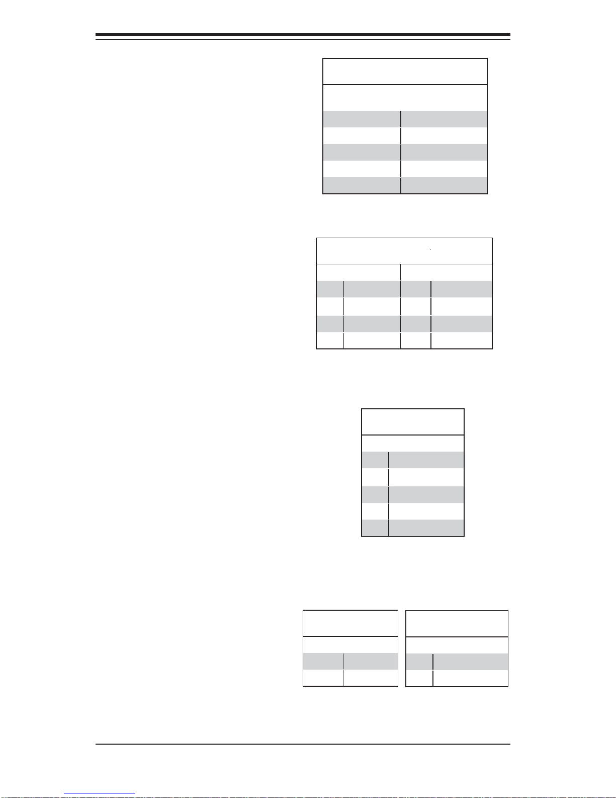
Universal Serial Bus
Pin Defi nitions (USB)
USB0/1/10/11
Pin # Defi nition
1 +5V 1 +5V
2 PO- 2 PO3 PO+ 3 PO+
4 Ground 4 Ground
5 N/A 5 Key
SGPIO Header
Pin Defi nitions (T-SGPIO-1/T-SGPIO-2)
Pin# Defi nition Pin Defi nition
1NC 2 NC
3 Ground 4 DATA Out
5 Load 6 Ground
7 Clock 8 NC
USB6/7/8/9
Pin # Defi nition
Power SMBUS Header
A Power SMB header is located at
SMBUS_PS. Connect the appropriate cable h er e to u ti li ze S M B o n you r
system. See the table on the right for
pin defi nitions.
Overheat LED/Fan Fail (JOH1)
The JOH1 header is used to connect
an LED to provide warning of chassis
overheating. This LED will blink to indicate a fan failure. Refer to the table
on right for pin defi nitions.
NC = No Connection
Power SMB Header
Pin Defi nitions (PW4)
Pin# Defi nition
1 Clock
2 Data
3 PWR Fail
4 Ground
5 +3.3V
OH/Fan Fail LED
States
State Message
Solid Overheat
Blinking Fan Fail
Overheat LED
Pin Defi nitions (JOH1)
Pin# Defi nition
1 5vDC
2 OH Active
5-16
Page 49
5-10 Jumper Settings
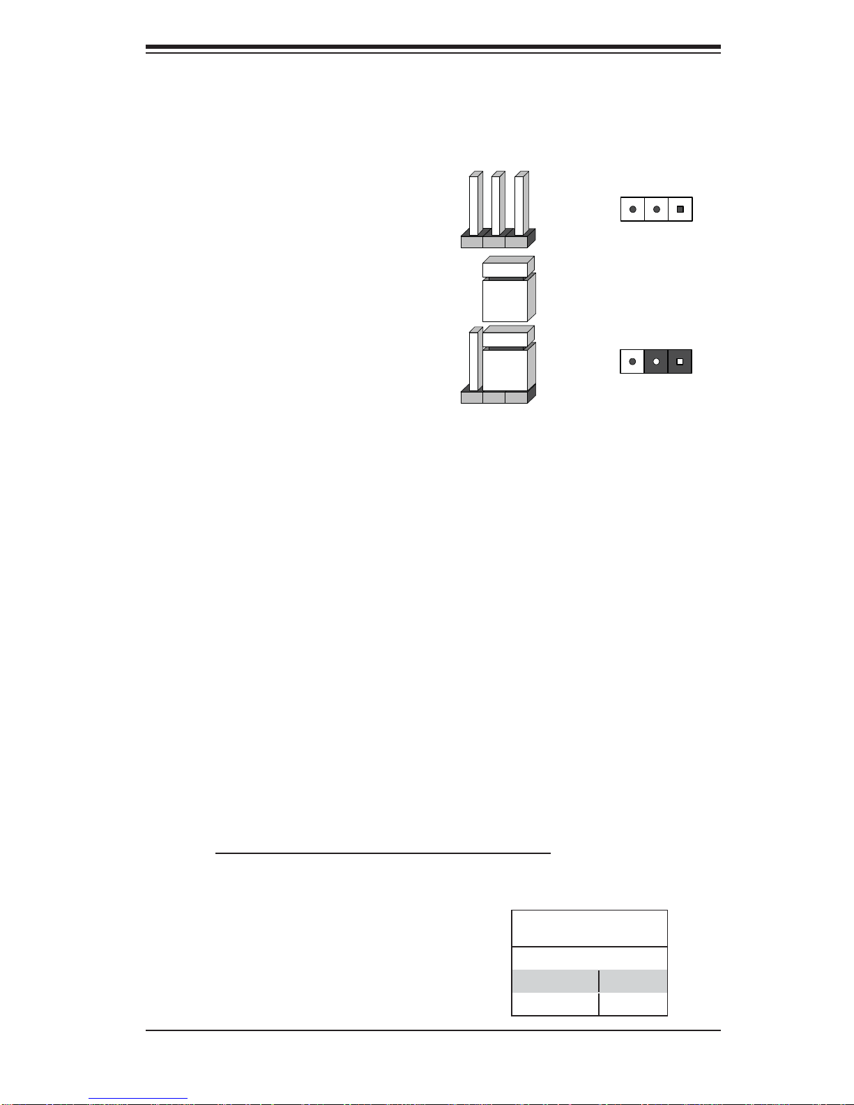
Explanation of Jumpers
To modify the operation of the
serverboard, jumpers can be used
to choose between optional settings.
Jumpers create shorts between two
pins to change the function of the connector. Pin 1 is identifi ed with a square
solder pad on the printed circuit board.
See the serverboard layout pages for
jumper locations.
Note: On a two-pin jumper, "Closed"
means the jumper is on both pins and
"Open" means the jumper is either on
only one pin or completely removed.
Chapter 5: Advanced Serverboard Setup
3 2 1
Connector
Pins
Jumper
3 2 1
Setting
CMOS Clear
JBT1 is used to clear CMOS (which will also clear any passwords). Instead of pins,
this jumper consists of contact pads to prevent accidentally clearing the contents
of CMOS.
To clear CMOS,
First power down the system and unplug the power cord(s).1.
With the power disconnected, short the CMOS pads with a metal object such 2.
as a small screwdriver.
Remove the screwdriver (or shorting device).3.
Reconnect the power cord(s) and power on the system.4.
Note: Do not use the PW_ON connector to clear CMOS.
VGA Enable/Disable
JPG1 allows you to enable or disable
the VGA port. The default position is on
pins 1 and 2 to enable VGA. See the
table on the right for jumper settings.
VGA Enable/Disable
Jumper Settings (JPG1)
Jumper Setting Defi nition
Pins 1-2 Enabled
Pins 2-3 Disabled
5-17
Page 50
SUPERSERVER 5015B-MT User's Manual
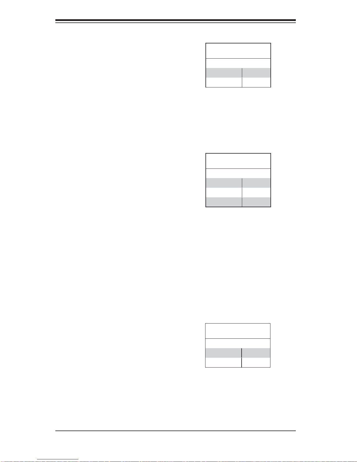
LAN1/2 Enable/Disable
Change the setting of jumper JPL1
and JPL2 to enable or disable the
LAN1 and LAN2 Ethernets ports, respectively. See the table on the right
for jumper settings. The default setting
is enabled.
Watch Dog Enable/Disable
JWD controls the Watch Dog function.
Watch Dog is a system monitor that
can reboot the system when a software
application hangs. Jumping pins 1-2
will cause WD to reset the system if an
application hangs. Jumping pins 2-3
will generate a non-maskable interrupt
signal for the application that hangs.
See the table on the right for jumper
settings. Watch Dog must also be enabled in BIOS.
LAN1/2 En/Disable Jump-
er Settings (JPL1/JPL2)
Jumper Setting Defi nition
Pins 1-2 Enabled
Pins 2-3 Disabled
Watch Dog
Jumper Settings (JWD)
Jumper Setting Defi nition
Pins 1-2 Reset
Pins 2-3 NMI
Open Disabled
Note: When enabled, the user needs to
write their own application software in
order to disable the Watch Dog Timer.
USB Wake-Up
These jumpers allow you to wake up the
system by pressing a key on the USB
keyboard or by clicking the USB mouse
of your system. The JPUSB jumpers are
used together with the USB Wake-Up
feature in BIOS and both must be enabled to use this feature. See the table
on the right for jumper settings. Notes:
JPUSB1 is for the USB0/1 ports and
JPUSB2 is for USB6/7/8/9/10/11.
Default settings are enabled for JPUSB1
and disabled for JPUSB2. Please be
sure to remove all other USB devices
from the USB ports whose USB jumpers
are set to Disabled before the system
goes into standby mode.
USB Wake-Up
Jumper Settings
Jumper Setting Defi nition
Pins 1-2 Enabled
Pins 2-3 Disabled
5-18
Page 51
SMBus to PCI-X/PCI-Exp. Slots
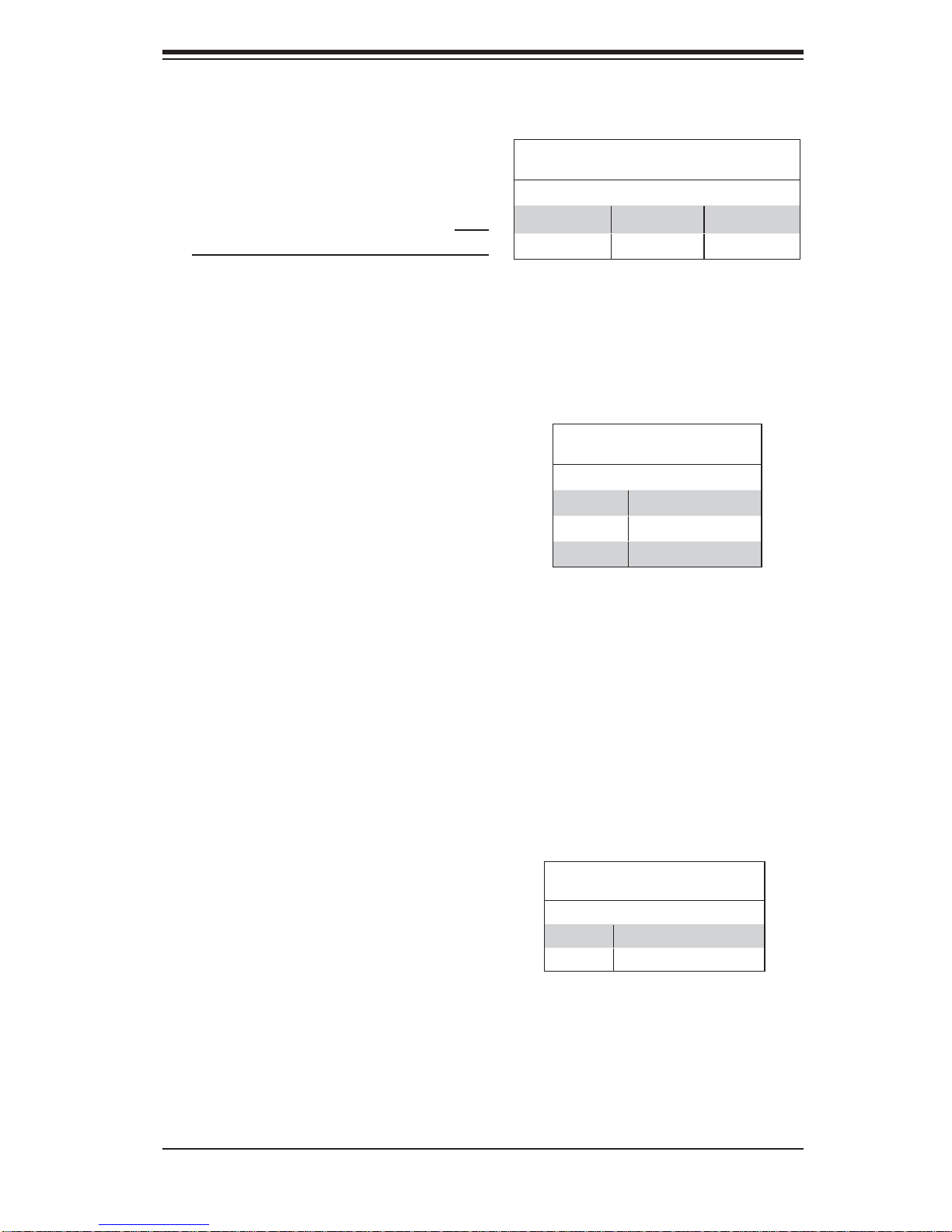
Chapter 5: Advanced Serverboard Setup
Jumpers JI
2
C1 and JI2C2 allow you to
connect the System Management Bus
2
(I
C) to the PCI-X/PCI-E slots. The
default setting is Open (Disabled.) Both
jumpers must be set to the same setting
See the table on the right for jumper
settings.
5-11 Onboard Indicators
LAN1/2 LEDs
The Ethernet ports (located beside
the VGA port) have two LEDs. On
each port, one LED indicates activity
while the other LED may be green,
amber or off to indicate the speed of
the connection. See the table on the
right for the functions associated with
the connection speed LED.
SMBus to PCI-X/PCI-E Slots
Jumper Settings (JI2C1/JI2C2)
Jumper Setting Defi nition
2
C1: Closed JI2C2:Closed Enabled
JI
2
JI
C1: Open JI2C2: Open Disabled
(Connection Speed Indicator)
LED Color Defi nition
Off 10 Mb/s
Green 100 Mb/s
Amber 1 Gb/s
GLAN1/2 LED
Onboard Power LED (LE1)
An Onboard Power LED is located at
LE1. This LED Indicator is lit when
the system is on. Be sure to unplug
the power cable before removing or
adding any components. See the table
on the right for more details.
Onboard Power LED Indicator
(LE1)
LED Color Defi nition
Off System Off
Green System on
5-19
Page 52
SUPERSERVER 5015B-MT User's Manual
5-12 Floppy, SATA, IPMI, IDE and Printer Ports
Floppy Drive Connector
The fl oppy connector is located be-
hind the mouse/keyboard ports. See
the table at right for pin defi nitions.
Floppy Drive Connector
Pin Defi nitions (Floppy)
Pin# Defi nition Pin # Defi nition
1 Ground 2 FDHDIN
3 Ground 4 Reserved
5 Key 6 FDEDIN
7 Ground 8 Index
9 Ground 10 Motor Enable
11 Ground 12 Drive Select B
13 Ground 14 Drive Select B
15 Ground 16 Motor Enable
17 Ground 18 DIR
19 Ground 20 STEP
21 Ground 22 Write Data
23 Ground 24 Write Gate
25 Ground 26 Track 00
27 Ground 28 Write Protect
29 Ground 30 Read Data
31 Ground 32 Side 1 Select
33 Ground 34 Diskette
SATA Ports
There are no jumpers to confi gure the onboard SATA ports.
See the table on the right for
pin defi nitions.
SIMSO
A SIMSO IPMI (Intelligent Platform Management Interface) 2.0
Socket is included on the motherboard.
Pin Defi nitions (SATA0~SATA5)
SATA Port
Pin # Defi nition
1 Ground
2 TXP
3 TXN
4 Ground
5 RXN
6 RXP
7 Ground
5-20
Page 53
Chapter 5: Advanced Serverboard Setup
IDE Connector
An IDE Connector is included on the
motherboard. See the table on the right
pin defi nitions.
IDE Drive Connectors
Pin Defi nitions (IDE)
Pin# Defi nition Pin # Defi nition
1 Reset IDE 2 Ground
3 Host Data 7 4 Host Data 8
5 Host Data 6 6 Host Data 9
7 Host Data 5 8 Host Data 10
9 Host Data 4 10 Host Data 11
11 Host Data 3 12 Host Data 12
13 Host Data 2 14 Host Data 13
15 Host Data 1 16 Host Data 14
17 Host Data 0 18 Host Data 15
19 Ground 20 Key
21 DRQ3 22 Ground
23 I/O Write 24 Ground
25 I/O Read 26 Ground
27 IOCHRDY 28 BALE
29 DACK3 30 Ground
31 IRQ14 32 IOCS16
33 Addr1 34 Ground
35 Addr0 36 Addr2
37 Chip DDR2 0 38 Chip DDR2 1
39 Activity 40 Ground
Parallel (Printer) Port
The paral lel por t is lo cated nex t to
COM2 header. See the table on the
right fo r pin defi nitions.
Parallel Port Connector
Pin Defi nitions (Printer)
Pin# Defi nition Pin # Defi nition
1 Strobe- 2 Auto Feed3 Data Bit 0 4 Error5 Data Bit 1 6 Init7 Data Bit 2 8 SLCT IN9 Data Bit 3 10 GND
11 Data Bit 4 12 GND
13 Data Bit 5 14 GND
15 Data Bit 6 16 GND
17 Data Bit 7 18 GND
19 ACK 20 GND
21 BUSY 22 Write Data
23 ___ 24 Write Gate
25 SLCT 26 NC
5-21
Page 54
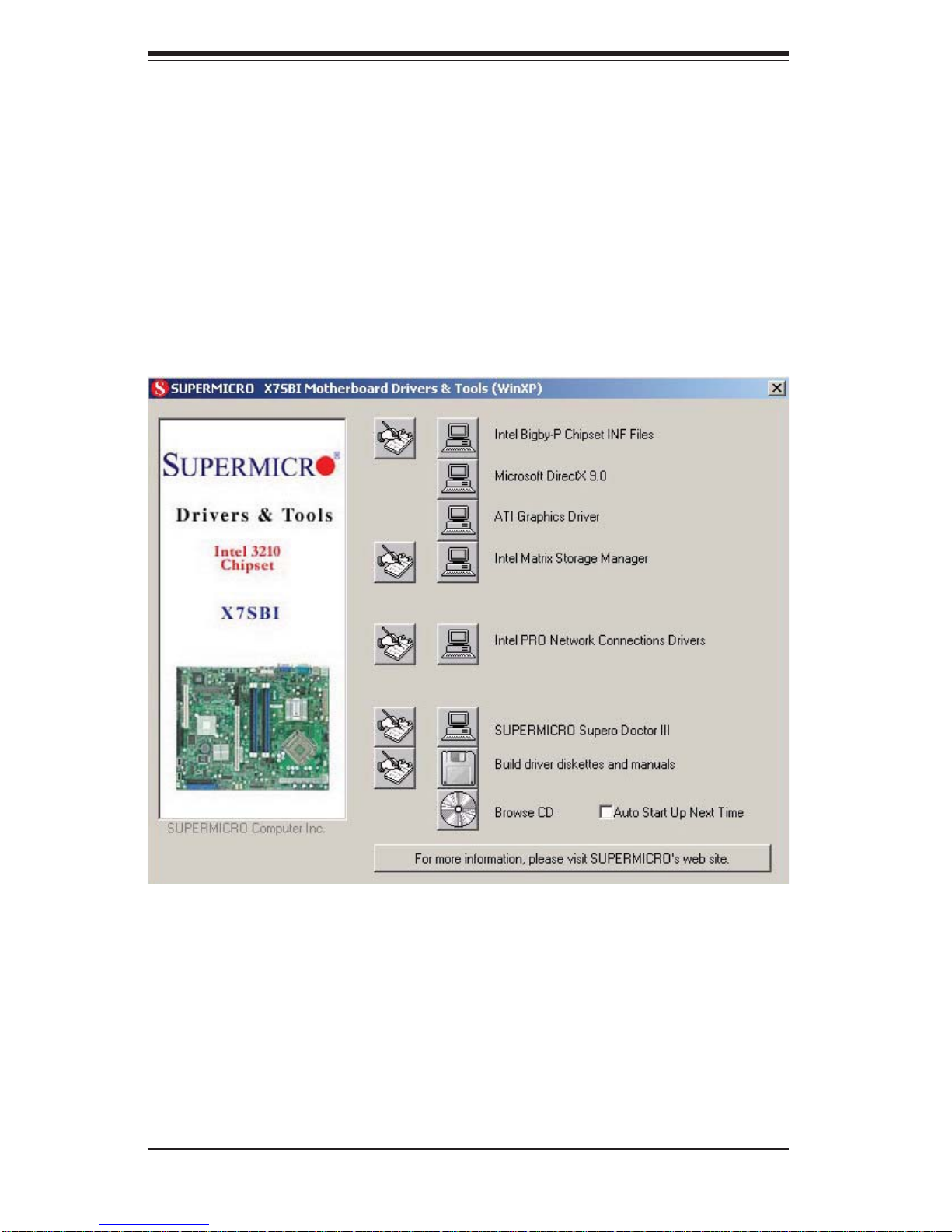
SUPERSERVER 5015B-MT User's Manual
5-13 Installing Drivers
After all the hardware and operating system have been installed, you need to install
certain drivers. The necessary drivers are all included on the Supermicro CD that
came packaged with your serverboard. After inserting this CD into your CD-ROM
drive, the display shown in Figure 5-5 should appear. (If this display does not appear ,
click on the My Computer icon and then on the icon representing your CD-ROM
drive. Finally, double click on the S "Setup" icon.)
Figure 5-5. Driver Installation Display Screen
Click the icons showing a hand writing on paper to view the readme fi les for each
item. Click the tabs to the right of these in order from top to bottom to install each
item one at a time. After installing each item, you must reboot the system be-
fore moving on to the next item on the list. You should install everything here
except for the SUPER Doctor utility, which is optional. The bottom icon with a CD
on it allows you to view the entire contents of the CD.
5-22
Page 55
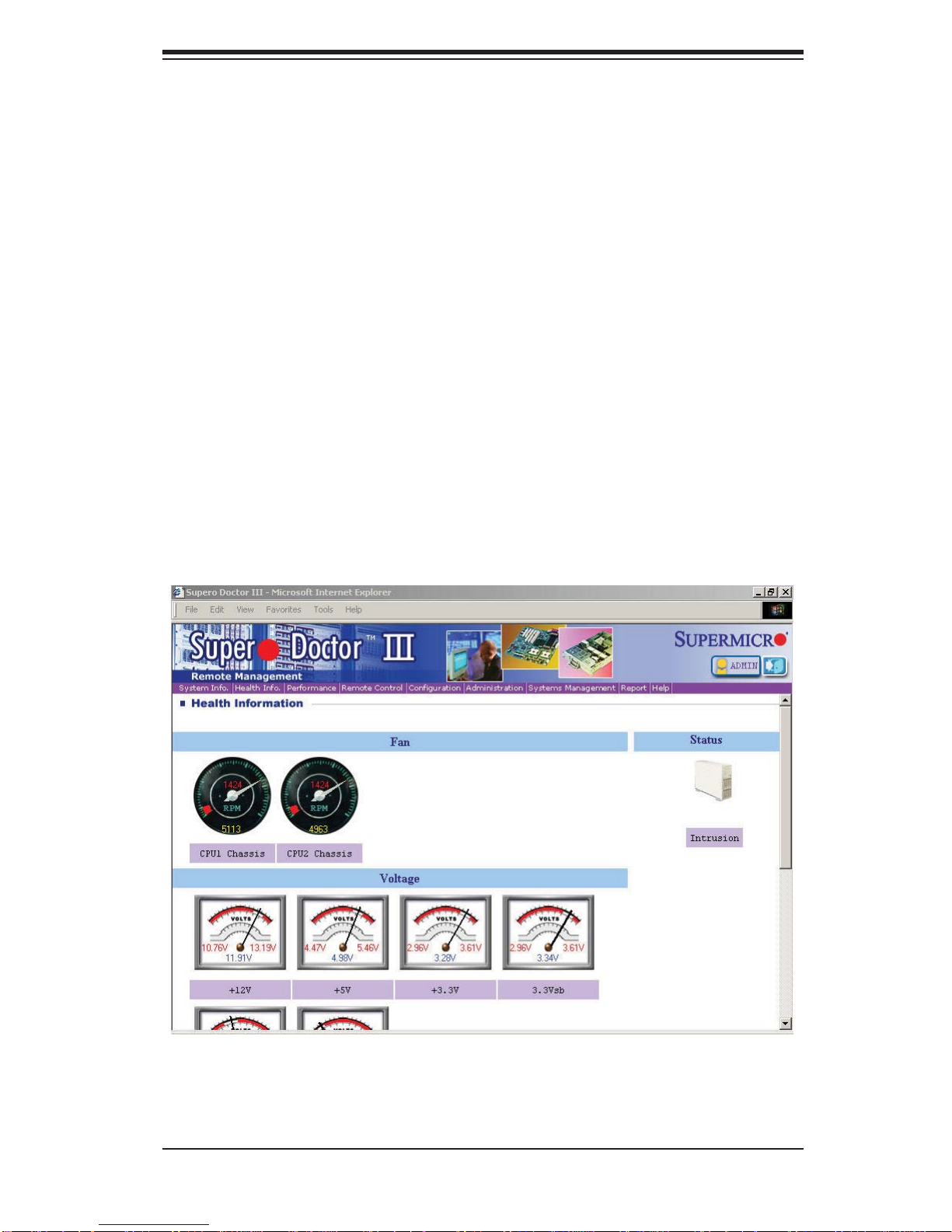
Chapter 5: Advanced Serverboard Setup
Supero Doctor III
The Supero Doctor III program is a web-based management tool that supports
remote management capability. It includes Remote and Local Management tools.
The local management is called SD III Client. The Supero Doctor III program included on the CD-ROM that came with your motherboard allows you to monitor
the environment and operations of your system. Supero Doctor III displays crucial
system information such as CPU temperature, system voltages and fan status. See
the Figure below for a display of the Supero Doctor III interface.
Note: The default User Name and Password for SuperDoctor III is ADMIN / ADMIN.
Note: When SuperDoctor III is fi rst installed, it adopts the temperature threshold
settings that have been set in BIOS. Any subsequent changes to these thresholds
must be made within Super Doctor, as the Super Doctor settings override the BIOS
settings. To set the BIOS temperature threshold settings again, you would fi rst need
to uninstall SuperDoctor III.
Supero Doctor III Interface Display Screen (Health Information)
5-23
Page 56
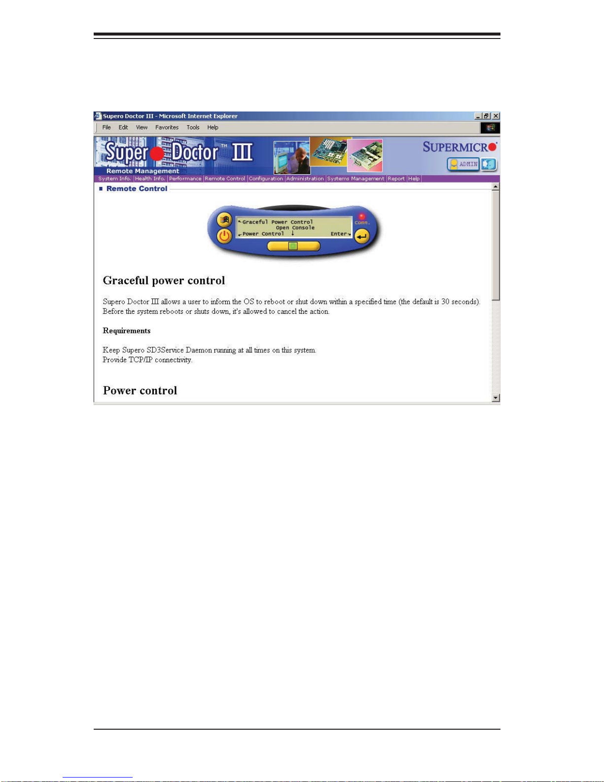
SUPERSERVER 5015B-MT User's Manual
Supero Doctor III Interface Display Screen (Remote Control)
Note: SD III Software Revision 1.0 can be downloaded from our Web Site at: ftp://ftp.
supermicro.com/utility/Supero_Doctor_III/. You can also download the SDIII User's
Guide at: <http://www.supermicro.com/PRODUCT/Manuals/SDIII/UserGuide.pdf>.
For Linux, we will recommend using Supero Doctor II.
5-24
Page 57

Chapter 6: Advanced Chassis Setup
Chapter 6
Advanced Chassis Setup
This chapter covers the steps required to install components and perform maintenance on the SC813MTQ-300C chassis. For component installation, follow the
steps in the order given to eliminate the most common problems encountered. If
some steps are unnecessary, skip ahead to the step that follows.
Tools Required: The only tool you will need to install components and perform
maintainance is a Philips screwdriver.
6-1 Static-Sensitive Devices
Electrostatic Discharge (ESD) can damage electronic com ponents. To prevent
damage to any printed circuit boards (PCBs), it is important to handle them very
carefully. The following measures are generally suffi cient to protect your equipment
from ESD discharge.
Precautions
Use a grounded wrist strap designed to prevent static discharge.•
Touch a grounded metal object before removing any board from its antistatic •
bag.
Handle a board by its edges only; do not touch its components, peripheral chips,
•
memory modules or gold contacts.
When handling chips or modules, avoid touching their pins.•
Put the motherboard, add-on cards and peripherals back into their antistatic •
bags when not in use.
For grounding purposes, make sure your computer chassis provides excellent
•
conductivity between the power supply, the case, the mounting fasteners and
the motherboard.
Unpacking
The motherboard is shipped in antistatic packaging to avoid static damage. When
unpacking the board, make sure the person handling it is static protected.
6-1
Page 58
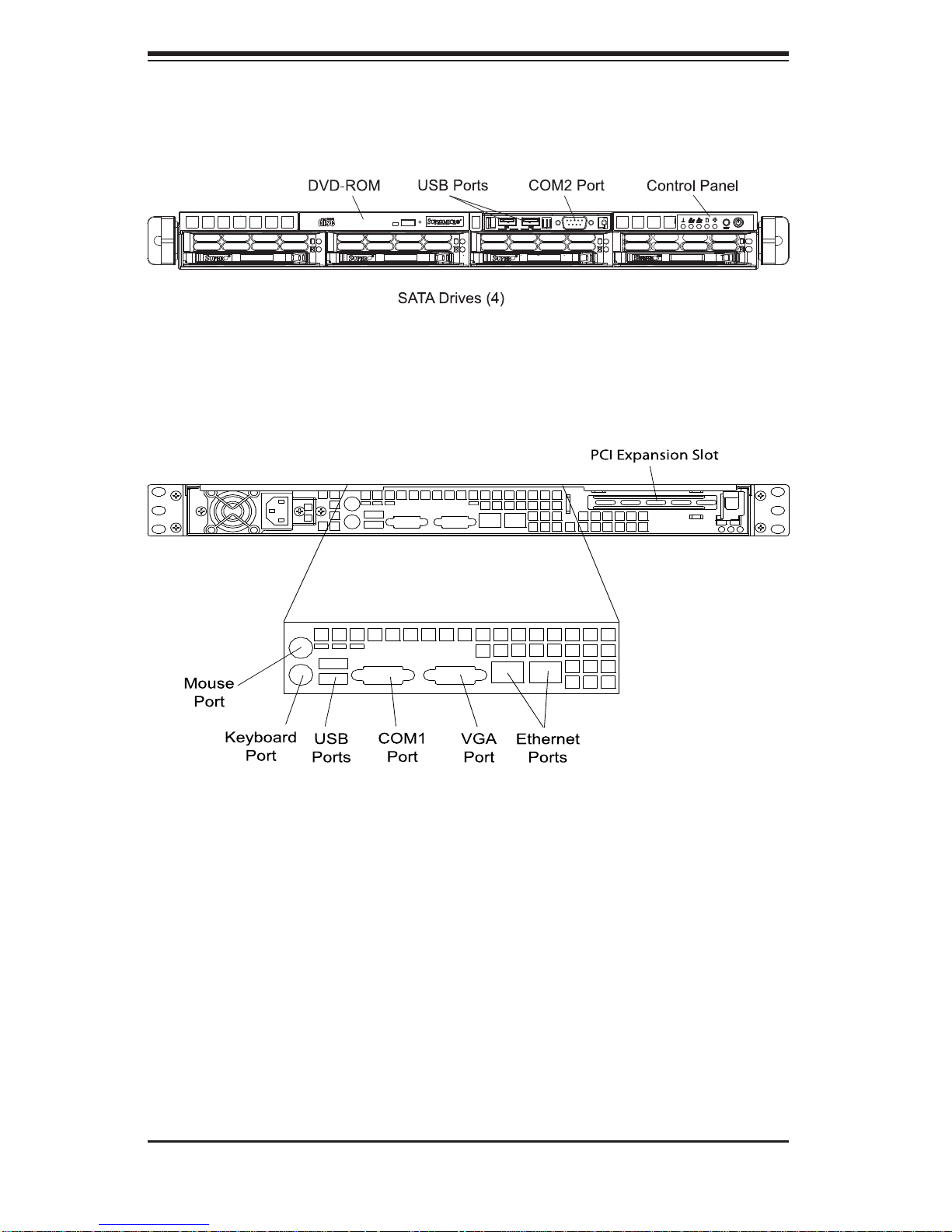
SUPERSERVER 5015B-MT User's Manual
Figure 6-1. Chassis Front View
Figure 6-2. Chassis Rear View
6-2 Control Panel
The control panel (located on the front of the chassis) must be connected to the
JF1 connector on the motherboard to provide you with system control buttons and
status indicators. These wires have been bundled together in a ribbon cable to
simplify the connection.
The LEDs inform you of system status. See Chapter 3 for details on the LEDs and
the control panel buttons. Details on JF1 can be found in Chapter 5.
6-2
Page 59
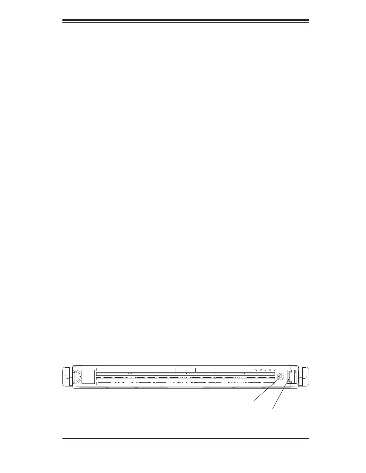
Chapter 6: Advanced Chassis Setup
6-3 System Fans
Four 4-cm high-performance fans provide the cooling for the SuperServer 5015BMT. The chassis includes air seals under the fans and at the chassis cross section,
which separates the drive bay area from the motherboard area of the chassis to
promote better airfl ow. It is highly important that the air seal is properly installed
and making a good seal in order for the cooling air to circulate properly through
the chassis.
The fans can adjust their speed according to the heat level sensed in the system,
which results in more effi cient and quieter fan operation. Fan speed is controlled
by a setting in BIOS.
System Fan Failure
If a fan fails, you will need to have it replaced with the same type. Contact your
vendor or Supermicro for information on replacement fans.
6-4 Drive Bay Installation/Removal
Removing the Front Bezel
If your system has a front bezel (optional) attached to the chassis, you must fi rst
remove it to gain access to the drive bays. To remove the bezel, fi rst unlock the
front of the chassis then press the release knob (see Figure 6-3). Carefully remove the bezel with both hands. A fi lter located within the bezel can be removed
for replacement/cleaning. It is recommended that you keep a maintenance log of
fi lter cleaning/replacement, since its condition will affect the airfl ow throughout the
whole system.
Figure 6-3. Removing the Front Bezel
1. Unlock
2. Press release knob
3. Remove bezel assembly
6-3
Page 60

SUPERSERVER 5015B-MT User's Manual
!
Accessing the Drive Bays
SATA Drives: Because of their hotswap capability, you do not need to access the
inside of the chassis or power down the system to install or replace SATA drives.
Proceed to the next step for instructions. Note: The operating system you use must
have RAID support to enable the hot-swap capability of the SATA drives.
CD-ROM Drive: For installing/removing a CD-ROM drive, you will need to gain access to the inside of the server by removing the top cover of the chassis. Proceed
to the "CD-ROM Drive Installation" section in this chapter for instructions. Note that
only a "slim" CD-ROM drive will fi t into the 5015B-MT.
Use caution when working around the SAT A backplane. Do not touch
the backplane with any metal objects and make sure no ribbon cables
touch the backplane. Also, regardless of how many SATA drives are
installed, all four drive carriers must remain in the chassis to maintain
proper airfl ow.
Serial ATA Drive Installation
Mounting a Serial ATA Drive in a Drive Carrier
The SATA drives are mounted in drive carriers to simplify their installation and
removal from the chassis. These carriers also help promote proper airfl ow for the
system. For this reason, even empty carriers without drives installed must remain
in the chassis.
Install a new SATA drive into the carrier with the printed circuit board side fac-1.
ing down so that the mounting holes align with those in the carrier.
Secure the drive to the carrier with six screws, as shown in Figure 6-4.2.
Figure 6-4. Mounting a Drive in a Carrier
6-4
Page 61
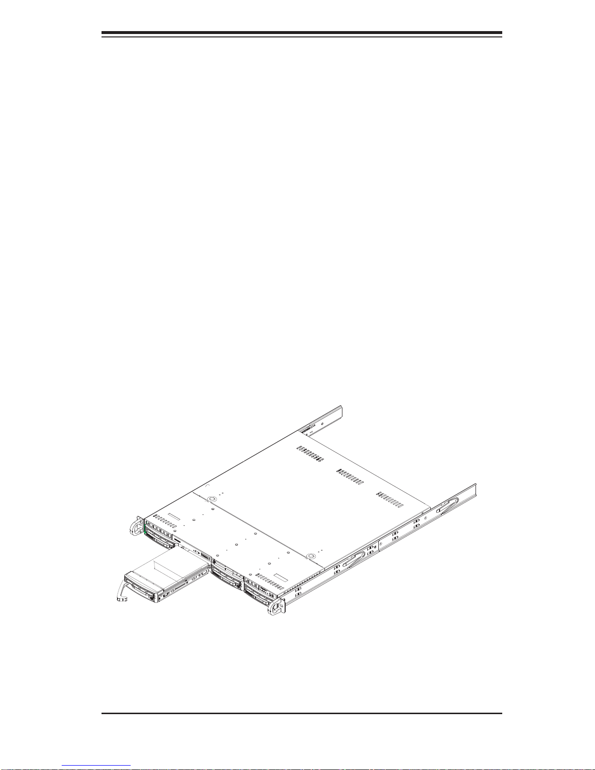
Chapter 6: Advanced Chassis Setup
Installing/Removing SATA Drives
To remove a carrier, push the release button located beside the drive LEDs.1.
Swing the colored handle fully out and use it to pull the unit straight out (see 2.
Figure 6-5).
Note: Your operating system must have RAID support to enable the hot-plug capability of the SATA drives.
Serial ATA Backplane
The Serial ATA drives plug into a backplane that provides power, drive ID and bus
termination. A RAID controller can be used with the backplane to provide data security. The backplane is already preconfi gured, so there are no jumpers or switches
present on it.
Figure 6-5. Removing a SATA Drive from the Server
6-5
Page 62

SUPERSERVER 5015B-MT User's Manual
DVD-ROM Drive Installation
The top cover of the chassis must be opened to gain full access to the DVD-ROM
drive bay. The 5015B-MT accomodates only slim DVD-ROM drives. Side mounting
brackets are needed to mount a slim DVD-ROM drive into the 5015B-MT server .You
must power down the system before installing or removing a DVD-ROM drive.
Removing the Chassis Cover
Grasp the two handles on either side and pull the unit straight out until it 1.
locks (you will hear a "click").
Depress the two buttons on the top of the chassis to release the top cover 2.
and at the same time, push the cover away from you until it stops. You can
then lift the top cover from the chassis to gain full access to the inside of the
server.
Removing/Installing a Drive
With the chassis cover removed, unplug the power and data cables from the 1.
drive.
Locate the locking tab at the rear of the drive. It will be on the left side of the 2.
drive when viewed from the front of the chassis.
Pull the tab away from the drive and push the drive unit out the front of the 3.
chassis.
Add a new drive by following this procedure in reverse order. You may hear a 4.
faint *click* of the locking tab when the drive is fully inserted.
Remember to reconnect the data and power cables to the drive before replac-5.
ing the chassis cover and restoring power to the system.
6-6
Page 63

Chapter 6: Advanced Chassis Setup
6-5 Power Supply
The SuperServer 5015B-MT has a single 300 watt power supply. This power supply
has the capability of operating at 100 - 240 input volts. Depress the main power
button on the front of the chassis and then unplug the AC power cord to completely
remove power from the system before removing the power supply.
Power Supply Failure
If the power supply unit fails, the system will shut down and you will need to replace
the power supply unit. Replacement units can be ordered directly from Supermicro
(PWS-0054 - see contact infomation in Chapter 1).
Replacing the Power Supply
To replace a power supply, you must fi rst remove the top chassis cover. Follow the
procedure on the previous page.
First unplug the power cord from the system.1.
To remove the failed power unit, remove the two screws on the back of the 2.
power supply, which secure it to the chassis. You can then lift the unit straight
out of the chassis.
Replace the failed unit with another unit of the same wattage. It is highly 3.
recommended to replace it with the exact same power supply.
Carefully insert the new unit into position in the chassis and secure it with the 4.
two screws at the rear of the unit.
Before reconnecting the power cord, make sure the power switch on the 5.
power supply is in the off position. Then reconnect the power cord, replace
the chassis top cover and push the unit back into the rack.
Finish by turning the power switch on the power supply on, and then depress 6.
the power button on the front of the system.
6-7
Page 64

SUPERSERVER 5015B-MT User's Manual
Notes
6-8
Page 65

Chapter 7: BIOS
Chapter 7
BIOS
7-1 Introduction
This chapter describes the Phoenix BIOS™ Setup utility for the X7SBi. The Phoenix ROM BI O S i s st o r e d i n a fl ash chip an d can be easi l y u p g r a d e d u si n g a fl oppy
disk-based program.
Note: Due to peri o d ic change s to t h e B I O S, s o m e s etting s may h ave be e n a dd e d
or deleted and might not yet be recorded in this manual. Please refer to the Manual
Download area of the Supermicro web site <http://www.supermicro.com> for any
change s to the BI OS that m ay not be refl ected in this manual.
System BIOS
BIOS is the Basic Input Output System used in all IBM® PC, XT™, AT®, and PS/2®
compatible computers. The Phoenix BIOS stores the system parameters, types of
disk dri ves, vide o displays, etc . in the CM OS. The C MOS me mor y require s very
little electrical power. When the computer is turned off, a backup battery provides
power to the CMOS logic, enabling it to retain system parameters. Each time the
computer is powered on the computer is confi gured with the values stored in the
CMOS l ogic by th e system BI OS, whi ch gain s cont rol at bo ot up.
How To Change the Co nfi guration Data
The CMO S infor mation t hat deter mines th e system para meters may b e change d
by entering t he B IO S S etup u ti lity. This Setup uti lity can b e ac c es s ed by pr es si ng
the <De lete> key at the app ropr iate time d uring sy stem boot . (See below.)
Star ti ng the S etup Ut ilit y
Norm ally, the onl y visi ble P OST (Powe r On S elf Test) routine is t he me mor y te st.
As the me mory is be ing tested, pre ss the <Del ete> key to enter the main menu
of the BIO S Setup utilit y. From the ma in menu, you can ac cess th e other setup
screens, such as the Security and Power menus. Beginning with Section 7-3,
detaile d desc ripti ons are g iven for e ach par ameter set ting i n the Set up utilit y.
Warning: Do not shut down or reset the system while updating BIOS to
prevent possible boot failure.
Note: The SPI BIO S ch ip use d in th e X7S Bi i s not re movab le. To replace a d am aged SPI B IOS ch ip, please s end th e mother boa rd to Supe rmic ro for r epair.
7-1
Page 66

SUPERSERVER 5015B-MT User's Manual
7-2 Running Setup
Default settings are in bold text unless otherwise noted.
The BIO S setup options de scribed in t his section a re selected by ch oosing the
approp r i ate tex t f r om t h e ma in B IO S S etu p sc r e en. All displ ayed tex t i s de s c r ib e d
in this section, although the screen display is of ten all you need to understand
how to set th e optio ns (See the n ext page).
When you fi r st power on the c omputer, the Phoenix B IOS™ is immediately act i-
vated.
While t he BIOS is in cont rol, the Setup pro gram can be act ivated in one of two
ways:
By pressing <Delete> immediately after turning the system on, or1.
When th e me ss age s how n be low a ppe ar s br ie fl y at the bottom of t he sc re en 2.
during the POST (Power On Self-Test), press the <Delete> key to activate
the main Setup menu:
Press the <Delete> key to enter Setup
7-3 Main BIOS Setup
All main Setup options are described in this section. The main BIOS Setup screen
is displayed below.
Use the Up / Do wn ar r ow keys to move am on g th e differe nt set t in gs in e ac h men u.
Use the +/- arrow keys to change the options for each setting.
Press the <Esc > key to exit the CMO S Setup Menu. The next sectio n d escri bes in
detail how to navigate through the menus.
Items that u se s ub m en us a re i n di cated with t h e
press the <Enter> key to access the submenu.
Xic on. With the item highlighted,
7-2
Page 67
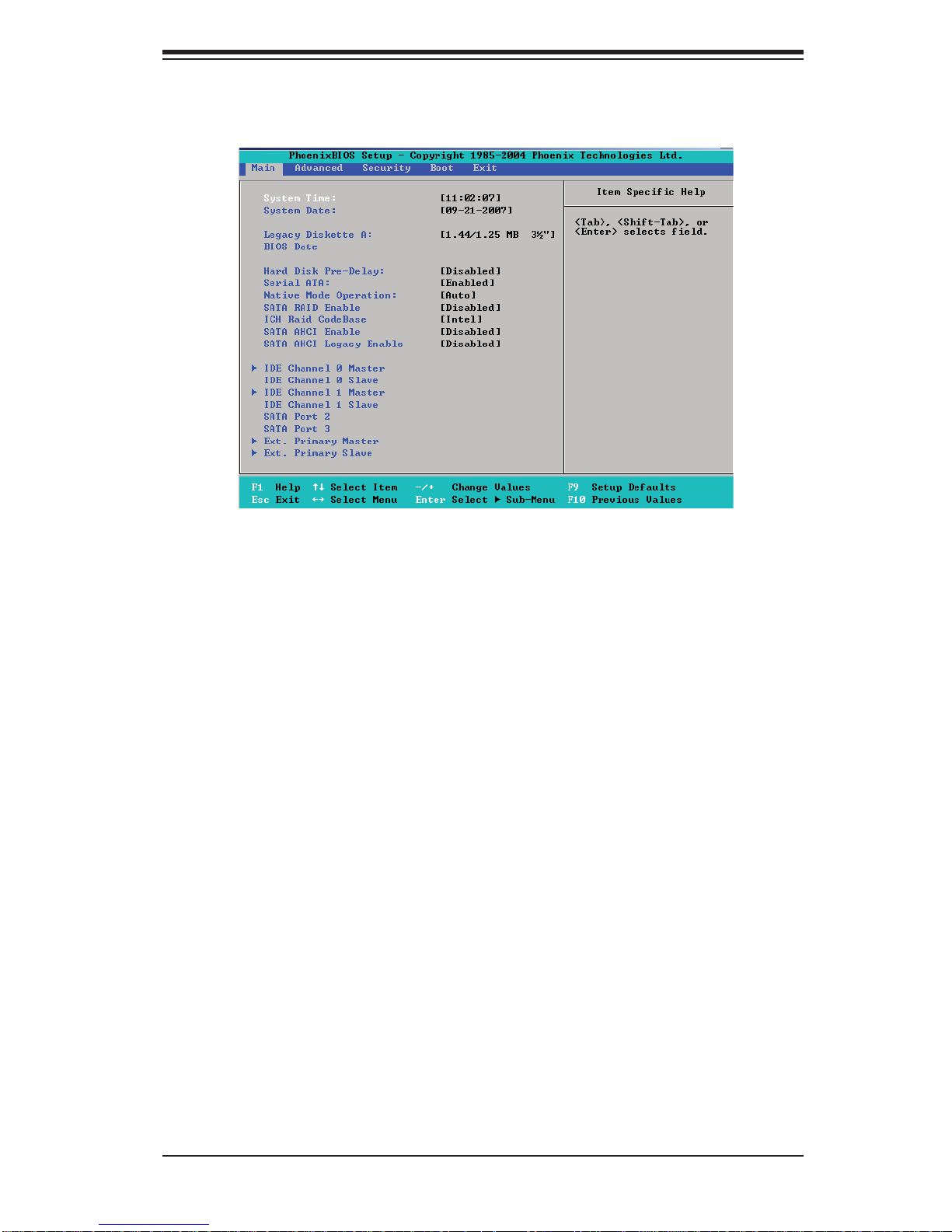
Main BIOS Setup Menu
Chapter 7: BIOS
Main Setup Features
System Time
To set the sys tem da te and t im e, key in the c o r re ct i nfo r mat io n in t he ap pr op r iate
fi elds. Then pr ess th e <Enter > key to save the dat a.
System Date
Using the arrow keys, highlight the month, day and year fi elds, and enter the
cor rect dat a. Pres s the <Ente r> key to save th e data.
Legacy Diskette A
This setting allows the user to set the type of fl oppy disk drive installed as
diskette A . The opt ions are D isabl ed, 36 0Kb 5. 25 in, 1.2M B 5.25 i n, 720K b 3.5
in, 1.44/1.25MB, 3.5 i n and 2. 88M B 3.5 in .
BIOS Date
The item dis plays the da te that the BI OS was buil t.
Hard Disk Pre-Delay
When Enab led, this featu re will add a delay to p rovide time ne ed for HDD se lfinitialization before the HDD is accessed by the BIOS for the fi rst time. Some
HDDs will hang if accessed by the BIOS without proper initialization. The options
are Enabl ed and Disabled.
7-3
Page 68

SUPERSERVER 5015B-MT User's Manual
Serial ATA
This setting allows the user to enable or disable the function of Serial ATA. The
option s are Dis abled a nd Enabled.
Native Mode Operation
Select Serial ATA to use the SATA mode, or select Auto to use the Native
Mode for ATA . The opti ons are: Serial ATA and Auto.
S e r i al ATA ( S ATA ) RA I D E n ab l e
Select Enable to enable Serial ATA RAID Functions. (For the Windows OS
environment, use the RAID driver if this feature is set to Enabled. When this
item is set to Enabled, the item: ICH RAID Code Base will be available for you
to select either Intel or Adaptec Host RAID fi rmware to be activated. If this item
is set to Disabled, the item -S ATA AHCI Enable w ill be availab le.) The options
are Enabl ed and Disabled.
ICH RAID Code Base
Selec t Intel to enable the I ntel SATA RAID fi rmwa re. Select Adapte c to use the
Adaptec HostRA ID fi rmware. The opt ions ar e Intel and Adaptec.
SATA AHCI
Select Enable to enable the function of Serial ATA Advanced Host Interface. (Take
cauti on w h en u si ng t h is f un c t io n. T hi s fe atu re i s fo r a dvan c e d p ro g ra mm ers only.
The Enhanced AHCI mode is available when the Windows XP-SP1 OS and the
IA A Dr iver is use d.) The options a re Enable d and Disabled.
SATA AHCI Leg acy
Select Enable to use Legacy Mode for SATA Advanced Host Interfacing. When
this featu re is set to Enab led, SATA Por t 5 and SATA Po rt 6 ar e disabl ed. (Take
caution when using this function. This feature is for advanced programmers only.)
The opti ons are En abled an d Disabled.
XIDE Channel 0 Master/Slave, IDE Channel 1 Master/Slave, SATA
Por t 2 , SATA Por t 3
These se ttings allo w the user to set the pa rameters of ID E Channel 0 Maste r/
Slave, ID E Channel 1 M aster/S lave, SATA Po rt 2 an d SATA Po rt 3 conn ectio ns.
Hit <Enter > to activate the following sub-menu screen for detailed options of
these items. Set the correct confi gurations accordingly. The items included in
the sub-menu are:
7-4
Page 69

Chapter 7: BIOS
Type
This option allows the user to select the type of an IDE/SATA device. Select
Auto to allow the BIOS to automatic ally confi gure the parameters of the IDE/
SATA devi ce install ed on a slot. Enter a num ber betwee n 1 to 39 to selec t a
predetermined IDE/SATA device. Select User to allow the user to enter the
parameters of a HDD/SA TA device installed. Select CDROM if a CDROM drive
is insta lled. Se lect ATAPI if a r emovable d isk dri ve is inst alled.
CHS Format
The foll owing i tems wil l be disp layed by the BI OS:
TYPE: This item displays the type of IDE drive.
Cylinders: This item indicates the number of cylinders detected by the
BIOS.
Headers: T his item ind icates t he number o f header s.
Sectors: This item displays the number of sectors.
Max im um C ap ac it y: T his i tem di spl ays th e ma xim um sto rag e c apac it y in t he
CHS Format.
LBA Format
The foll owing i tems wil l be disp layed by the BI OS:
To t al Sect o rs : This item displays the number of total sectors available in the
LBA Format.
Maximum Capacity: This item displays the maximum capacity in the LBA
Format.
Multi-Sector Transfers
This item allows the user to specify the number of sectors per block to be
used in mul ti - se cto r tr ansf er. The opti ons a re Disabled, 4 Sec tor s, 8 Se ct or s,
and 16 Sectors.
LBA Mode Cont rol
This item dete rmi nes wh ether t he Phoe nix BI OS wil l acc ess a I DE Dev ice v ia
the LBA m ode. The o ption s are Enabl ed and Disabled.
32 Bit I/O
This option allows the user to enable or disable the function of 32-bit data
transf er. The option s are Enabl ed and Disabled.
7-5
Page 70

SUPERSERVER 5015B-MT User's Manual
Tr a n s fe r M o de
This option allows the user to set the transfer mode. The options are Standard, Fast
PIO1, Fast PIO2, Fast PIO3, Fast PI O4, FPIO 3/D MA1 and FPIO4/ DM A 2.
Ultr a DMA Mo de
This option allows the user to confi gure the Ultra DMA Mode setting. The options
are Disabled, Mode 0, Mode 1, Mode 2, Mode 3, Mode 4, and Mode 5.
XE xtended Primary Master/Slave
These settings a ll ow t he us er t o set t he p ar am eter s of Exten de d Pr im ary Maste r/
Slave connections. Hit <Enter> to activate the following sub-menu screen for
detail ed options of th ese items. Set the c orrect c onfi gurations acc ordingly. The
items included in the sub-menu are:
Type
This option allows the user to select the type of an IDE device. Select Auto
to allow the BIOS to automatically co nfi gure the param eter s of th e ID E devi ce
install ed on a s lot. Ente r a numbe r bet wee n 1 to 39 to s ele ct a pr edeter mi ned
IDE devic e. Sel ect U ser to all ow the u ser to ente r the par ameter s of the H DD
installed. Select CDROM if a CDROM drive is installed. Select ATAPI if a
removabl e disk dr ive is inst alled.
LBA Format
The foll owing i tems wil l be disp layed by the BI OS:
To t al Sect o rs : This item displays the number of total sectors available in the
LBA Format.
Maximum Capacity: This item displays the maximum capacity in the LBA
Format.
Multi-Sector Transfers
This item allows the user to specify the number of sectors per block to be
used in mul ti - se cto r tr ansf er. The opti ons a re Disabled, 4 Sec tor s, 8 Se ct or s,
and 16 Sectors.
LBA Mode Cont rol
This item dete rmi nes wh ether t he Phoe nix BI OS wil l acc ess a I DE Dev ice v ia
the LBA m ode. The o ption s are Enabl ed and Disabled.
32 Bit I/O
This option allows the user to enable or disable the function of 32-bit data
transf er. The option s are Enabl ed and Disabled.
7-6
Page 71
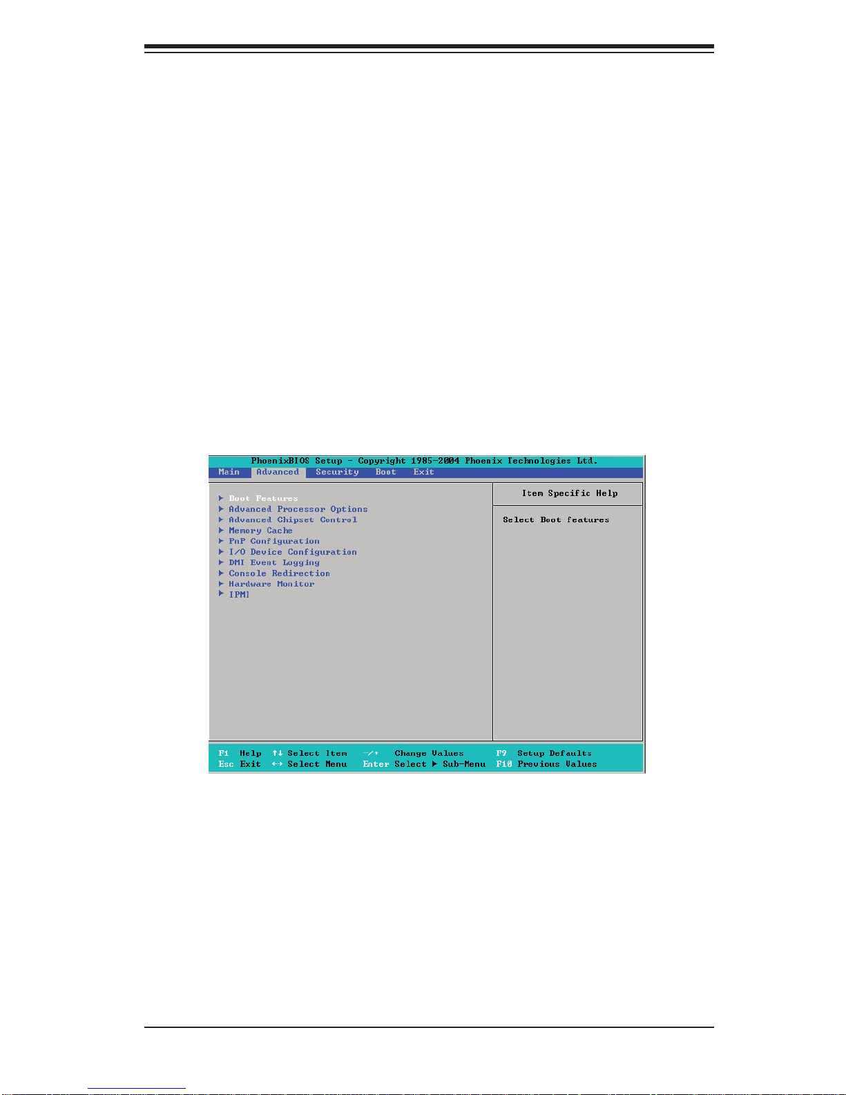
Chapter 7: BIOS
Tr a n s fe r M o de
This option allows the user to set the transfer mode. The options are Standard, Fast
PIO1, Fast PIO2, Fast PIO3, Fast PI O4, FPIO 3/D MA1 and FPIO4/ DM A 2.
Ultr a DMA Mo de
This option allows the user to confi gure the Ultra DMA Mode setting. The options
are Disabled, Mode 0, Mode 1, Mode 2, Mode 3, Mode 4, and Mode 5.
System Memory
This dis play infor ms you ho w much syste m memo ry i s detecte d in the syste m.
7-4 Advanced Setup
Choose Advanced from the Phoenix BIOS Setup Utility main menu with the arrow
keys. You should see the following display. The items with a triangle beside them have
sub menus that can be accessed by highlighting the item and pressing <Enter>.
XBoot Features
Acce ss the s ubmenu to m ake chang es to the f ollow ing set tings.
Quiet Mode
This set ting allows yo u to Enable or Disable th e graphic log o screen dur ing
boot -up.
QuickBoot Mode
If enabled, this feature will speed up the POST (Power On Self Test) routine by
skipping certain tests after the computer is turned on. The settings are Enabled
7-7
Page 72

SUPERSERVER 5015B-MT User's Manual
ACPI M od e
Select Yes to use the ACPI (Advanced Confi guration and Power Interface)
power mana gement fe ature on yo ur system. Th e optio ns are Yes and No.
Power But to n Be havi or
If set to Instant-O f f, the system will power on or power off immediately as
soon as t he user hits the powe r button. The opt ions are Instant-Of f and 4Sec ond O ver rid e.
Resume On M odem Ri ng
Select On to “wake your system up” when an incoming call is received by your
modem. T he opti ons are O n and Off.
Resume On PME #
Selec t On to “ wake your syste m up” from t he PME # of PCI sl ots. The o ption s
are On and Off.
PS2 Keyboard (KB)/Mouse Wake Up
Select Enable to “wake your system up” from the S1, S4 or S5 state. If this
feature is set to Enabled, you will also need to enable the JPWAKE jumper by
closi ng p in s 1-2. ( Pl ea se r efe r to Pg. 1-5 and Cha pte r 2 fo r m o re d et ai l s). The
default set tin g is Disabled.
Power Los s Con tr ol
This setting allows you to choose how the system will react when power returns
after a n unexpe cte d los s of powe r. The optio ns are S tay O f f, Power On, a nd
Last State.
Watch Do g
If enabled, this option will automatically reset the system if the system is not
active f or more t han 5 minute s. The op tions a re Enable d and Disabled.
Summary Scre en
This setting allows you to Enable or Disable the summary screen which displays
the system confi gura tio n dur ing b ootu p.
XAdvan ced Pro cesso r Opti ons
Acce ss the s ubmenu to m ake chang es to the f ollow ing set tings.
CPU Speed
This is a dis play that in dicate s the spe ed of the in stalle d proc esso r.
7-8
Page 73

Chapter 7: BIOS
Frequenc y Ratio (Avai labl e whe n supp or ted by t he CPU.)
The featur e allows the use r to set the intern al frequenc y multiplie r for the CPU.
The defau lt sett ing is Def ault .
Frequenc y High Rat io (Availa ble w hen sup por te d by the CPU.)
The featur e allows t he use r to set high r atio i nterna l freq uency m ultip lier fo r Intel
Speed Step CPU s. The defa ult set ting is x12.
Note: If a wrong rat io that is not sup ported by t he CPU is selec ted, the system
may hang. If t his hap pens, c lear C MOS to r ecover t he syste m.)
Hyperthreading (Availa ble wh en sup por te d by the CPU.)
Set to Enabled to use the Hyperthreading Technology, which will result in increased
CPU per for manc e. The op tions a re Disa bled an d Enabled.
Core-Multi-Processing (Availa ble wh en sup por te d by the CPU.)
Set to Enabl ed to use a proc essor 's Secon d Core and beyon d. (Please refe r to
Intel's web s ite for mor e infor mation.) The opti ons are Di sable d and Enabled.
Machine Checking (Available w hen su ppor t ed by th e CPU.)
Set to Enabled to activate the function of Machine Checking and allow the CPU to
detect and r ep or t h ard ware (mach ine) erro rs v ia a set o f mod el - sp ec ifi c registers
(MSRs). The opt ions ar e Enabled and Disabled.
Compatib le FPU Code (Availabl e when s uppo rt ed by th e CPU.)
Set to Enabled to keep the content of the last instruction Operating C ode (OP
Code) in the fl oating p oint (FP) state. The o ptions a re Disabled and Enabled.
L3 Cache(Available w hen su ppor t ed by th e CPU.)
Set to Enabl ed to enable t he func tion of L3 C ache to opti mize system and C PU
per for mance. T he opti ons are D isabl ed and Enabl ed.
Ther mal Man agem ent 2 (Availa ble w hen sup por t ed by the C PU.)
Set to Enabled to use Thermal Management 2 (TM2) which will lower CPU voltage
and frequency when the CPU temperature reaches a predefi ned overheat threshold.
Set to Dis abled to use Th ermal Mana ger 1 (TM1), allowing CPU c locking t o be
regulated via CPU Internal Clock modulation when the CPU temperature reaches
the overheat threshold.
Adjacent Cache Line Prefetch (Available w hen sup por te d by the C PU.)
The CPU fetc h es t h e c a c he l in e fo r 64 bytes i f th is o pt i on i s s et to D is a bl e d. Th e
CPU fetches both ca che lines for 128 bytes as comprised if Enabled. The options
are Dis abled an d Enabled.
7-9
Page 74

SUPERSERVER 5015B-MT User's Manual
Set Ma ximu m Ext . CPUI D=3
When set to Enabled, the Maximum Extended CPUID will be set to 3. The options
are Disabled and Enabled.
Echo TPR
Set to Enabled to prevent xTPR messages from being sent to the system.The
option s are Dis abled a nd Enabled.
C1 Enh an ced Mod e (Availa ble w hen sup por t ed by the C PU.)
Set to Enable d to e nab le Enh an c ed H alt S t ate to lo wer C PU vol t age / f re que nc y to
prevent over heat . The o pti ons a re Enab led a nd Disabled. Note: please refer to
Intel’s web site for det ailed in format ion.
Inte l <R> Vir tualiz ation Technolo gy (Available when supported by the
CPU.)
Select Enabled to use the feature of Virtualization Technology to allow one platform
to run multiple operating systems and applications in independent partitions, creating
multip l e " v i rtual " sy s te m s in o n e p hys i cal com p ut e r. The opt i o ns a r e En ab l e d a n d
Disabled. Note: If there is any cha nge to t his s et tin g, you wi ll ne ed to p ower of f
and rest art the sy stem for the ch ange to take ef fect. Pleas e refer to Intel’s web
site for detailed information.
No Execute Mode Memory Protection (Available when supported by
the CPU a nd th e OS.)
Set to Enabl ed to en abl e Exe cute D is abl e Bit an d all ow th e pro ce ss or to c las sif y
areas in memory where an application code can execute and where it cannot, and
thus prevent ing a wor m or a v ir us fr om ins er t ing an d cre atin g a fl ood of codes to
over whelm t he proc ess or or dam age the sy stem dur ing an at tack .
Note: this feature i s availabl e when you r OS and your C PU suppo rt t he func tio n
of Execu te Disabl e Bit. The o ptions ar e Disable d and Enabled. Note: For more
inform at i on r e ga r di ng h ar d war e /soft war e su pp o rt for t hi s f un c t io n, p l ea se r ef er to
Intel's and M icro soft 's web s ites.
Enhanc ed In tel S pee d Step S uppo r t (Available when supported by the
CPU.)
Select Enabled to use the Enhanced Intel SpeedStep Technology and allows
the system t o automatic ally adjust p rocess or voltage an d core fre quency in an
effo rt to red uce power c onsumpti on and heat dis sipatio n. The default s etting i s
GV1/GV3. Please refe r to Intel’s web site fo r detaile d infor mation.
XAdvan ced Chi pset Con trol
Acce ss the s ubmenu to m ake chang es to the f ollow ing set tings.
7-10
Page 75

Chapter 7: BIOS
Warning: Take Caution when changing the Advanced settings. An incor-
rect value, a very high DRAM frequency, or an incorrect DRAM timing may
cause t he system to bec ome unstabl e. When this o ccurs, re set the setti ng
to the defaul t sett ing.
Memory Reclaiming
Selec t En a b l e to e n ab l e the func t i o n a li ty of Mem o ry Rema p pi n g a b ove 4 GB. The
settings are Enabled and Disabled.
Enable VT-d
Selec t Ena b le t o en ab l e t he functi o na li ty of the Inte l V irtual ization Technolo g y fo r
Direc t I/O suppor t, which off ers fully-p rotected I/O reso urce-s haring acros s the
Intel plat for ms, pr ovidi ng the u ser wit h greate r reli abilit y, secur it y and availa bilit y
in netw orki ng and dat a- shari ng. The s ettin gs are Enab led and Disabled.
High Pre cisio n Event Time
Select Yes to activate the High Precision Event Timer (HPET), which is capable
of producing periodic interrupts at a much higher frequency than a Real-time
Clock (RTC) can in synchronizing multimedia streams, providing smooth playback
and reduc ing the depende ncy on other timest amp calculat ion devices, suc h as
an x86 R DTSC Ins tr uc tio n emb edd ed in a C PU. The H igh P rec isi on Event Ti mer
is used to replace the 8254 Programmable Interval Timer. The options for this
feature are Yes and No.
Route Por t 8 0h Cycl es to
This featu re allows the user to d ecide which b us to send debug info rmation to.
The opti ons are D isabl ed, PCI and LPC.
Legacy USB Support
This set tin g allo ws you to en able su ppo r t for Le gacy US B devi ces . The set ti ngs
are Enabled and Disabled.
USB Host Controll er 1
This feature allows the user to confi gure the USB Host Controller setting for
USB Host Controller 1 Functions 0, 1, 2, 3, 7. The settings are Enabled and
Disabled.
USB Host Controll er 2
This featur e a ll ow s t he u se r to confi gure the USB H o st Contro ll e r setting fo r U S B
Host Co ntroll er 2 Functi ons 0, 1, 2, 7. T he sett ings are Ena bled and Disabled.
7-11
Page 76

SUPERSERVER 5015B-MT User's Manual
XMemory Cache
Cache Syst em BIOS A rea
This set ting al lows you to de signate a r eser ve area in t he system me mor y to be
used as a Sy stem BIOS buf fer to allow th e BIOS to wri te (cac he) data into t his
reser ved memory area. Select Write Protect to enable this function, and this
area will be reserved for BIOS ROM access only. Select Uncached to disable
this function and make this area available for other devices.
Cache Vi deo BI OS Area
This set ting al lows you to de signate a r eser ve area in t he system me mor y to be
used as a Video BIOS buffer to allow the BIOS to write (cache) data into this
reserved memory area. Select Write Protect to enable the function and this area
will be re served fo r Video BIOS RO M access o nly. Select Unca ched to disabl e
this function and make this area available for other devices.
Cache Base 0 - 512K
If enable d, t hi s feat ure w il l al low t he d at a sto re d in t he b ase m em o ry area: blo c k
0- 512K to be cac hed (written) into a buf fer, a storage area in t he Static DRO M
(SDROM) or to b e w ritten i nt o t h e L1, L2 c ache insid e t h e C PU t o sp e e d u p C PU
operations . Select Uncached to disable this function. Select Write Through to
allow data to be cached into the buffer and written into the system memory at the
same tim e. Sel ec t Wri te Prote ct to p revent dat a fr om be ing w ri tte n into t he bas e
memor y ar ea of Blo ck 0 - 512K. S elec t Write B ack to all ow the C PU to wri te data
back dir ectly fr om the buf fer wit hout wr iting dat a to the Syste m Memor y for fas t
CPU data p roc e ss ing a nd op er ati on. T he opt io ns ar e Unc a ch ed, Wr ite T hr oug h,
Write Prote ct, an d Writ e Back.
Cache Base 512K-6 40K
If enable d, th is feat ure w ill a llow t he dat a sto re d in th e mem or y a rea: 512K-6 40 K
to be cac he d (wr it te n) into a buf fe r, a storage ar ea in t he S tat ic D RO M (SD RO M)
or writ ten i nto the L1, L2, L3 c ac he insi de the C PU to spe ed up CP U oper atio ns.
Selec t Uncach ed to disable t his funct ion. Selec t Write Thr ough to allow dat a to
be cac he d into t h e buffer an d wr i t te n into t h e syste m me mo ry at the s am e ti me.
Select Write Protect to prevent data from being written into the base memory
area of Bl oc k 512K-64 0K . Se lec t Wri te Bac k to all ow th e CPU to w ri te dat a back
direct ly from t he buff er withou t writin g data to the S ystem Mem ory fo r fast CPU
data process i ng and oper ation. The o p tions are U n cached , Write Thro ugh, Write
Protect, and Wri te Bac k.
7-12
Page 77

Chapter 7: BIOS
Cache Ex tend ed Mem ory
If enable d, thi s featu re wi ll all ow th e dat a stor ed in t he exte nde d mem ory area to
be cac hed (writ ten) into a buffer, a storage a rea in the St atic DROM (SD ROM)
or writ ten i nto the L1, L2, L3 c ac he insi de the C PU to spe ed up CP U oper atio ns.
Select Uncached to disable this function. Select Write Through to allow data
to be cac hed into the buf fer and wri tten into the syste m memory at t he same
time. Sel ect Wri te Protect to pr event data fro m being wr itte n into the exte nded
memory area a b ove 1 MB. Sel ect Write B ac k to a ll o w t h e C PU t o w rite data b ack
direct ly from t he buff er withou t writin g data to the S ystem Mem ory fo r fast CPU
data process i ng and oper ation. The o p tions are U n cached , Write Thro ugh, Write
Protect, and Wri te Bac k.
XPn P Confi guration
Acce ss the s ubmenu to m ake chang es to the f ollow ing set tings f or PCI devi ces.
XPCI 32 Sl ot
Access the submenu for each of the settings above to make changes to the
following:
Option ROM Scan
When enabled, this setting will initialize the device expansion ROM. The options
are Enabled and Disabled.
Enable Master
This set ting all ows you to enab le the sel ected dev ice as th e PCI bus mast er.
The opti ons are En abled an d Disabled.
Latency Timer
This setting allows you to set the clock rate for Bus Master. A high-priority,
high-throughout device may benefi t from a greate r cl oc k rate. T he o pti ons a re
Default, 0020h, 0040h, 0060h, 0080h, 00A0h, 00C0h, and 00E0h. For Unix,
Novelle and other Operating Systems, please select the option: other. If a drive
fails after the installation of a new software, you might want to change this setting
and tr y again. A d iff erent OS re quires a d iff erent Bus M aster c lock r ate.
PCI-X(s) Fr equency
When set to Enabled, this featu re allow s the use r to set the b us fre quenc y for a
PCI-X sl ot for it to wor k prop erly. The defau lt sett ing is Aut o.
7-13
Page 78

SUPERSERVER 5015B-MT User's Manual
XPC I-X 133 MHz Sl ot
Access the submenu for each of the settings above to make changes to the
following:
Option ROM Scan
When enabled, this setting will initialize the device expansion ROM. The options
are Enabled and Disabled.
Enable Master
This set ting all ows you to enab le the sel ected dev ice as th e PCI bus mast er.
The opti ons are En abled an d Disabled.
Latency Timer
This setting allows you to set the clock rate for Bus Master. A high-priority,
high-throughout device may benefi t from a greate r cl oc k rate. T he o pti ons a re
Default, 0020h, 0040h, 0060h, 0080h, 00A0h, 00C0h, and 00E0h. For Unix,
Novelle and other Operating Systems, please select the option: other. If a drive
fails after the installation of a new software, you might want to change this setting
and tr y again. A d iff erent OS re quires a d iff erent Bus M aster c lock r ate.
XPCI -E xp. x8 Slot
Access the submenu for each of the settings above to make changes to the
following:
Option ROM Scan
When enabled, this setting will initialize the device expansion ROM. The options
are Enabled and Disabled.
Enable Master
This set ting all ows you to enab le the sel ected dev ice as th e PCI bus mast er.
The opti ons are En abled an d Disabled.
Latency Timer
This setting allows you to set the clock rate for Bus Master. A high-priority,
high-throughout device may benefi t from a greate r cl oc k rate. T he o pti ons a re
Default, 0020h, 0040h, 0060h, 0080h, 00A0h, 00C0h, and 00E0h. For Unix,
Novelle and other Operating Systems, please select the option: other. If a drive
fails after the installation of a new software, you might want to change this setting
and tr y again. A d iff erent OS r equire s a dif ferent Bu s Master c loc k rate.
7-14
Page 79

Chapter 7: BIOS
XOnbo ard L AN 1/Onboa rd LA N 2
Access the submenu for each of the settings above to make changes to the
following:
Option ROM Scan
When enabled, this setting will initialize the device expansion ROM. The options
are Enabled and Disabled.
Enable Master
This set ting all ows you to enab le the sel ected dev ice as th e PCI bus mast er.
The options are Enabled and Disabled.
Latency Timer
This setting allows you to set the clock rate for Bus Master. A high-priority,
high-throughout device may benefi t from a greate r cl oc k rate. T he o pti ons a re
Default, 0020h, 0040h, 0060h, 0080h, 00A0h, 00C0h, and 00E0h. For Unix,
Novelle and other Operating Systems, please select the option: other. If a drive
fails after the installation of a new software, you might want to change this setting
and tr y again. A d iff erent OS re quires a d iff erent Bus M aster c lock r ate.
XI/O Device Confi guration
Acce ss the s ubmenu to m ake chang es to the f ollow ing set tings.
KBC Cloc k Inpu t
This setting allows you to select clock frequency for the keyboard clock. The
option s are 6M Hz, 8M Hz, 12MHz, and 16MHz.
Serial Port A
This setting allows you to assign control of Serial Port A. The options are Enabled
(us e r d e fi ned), Disable d, and Auto (B IOS - or OS - co ntroll ed).
Base I/O Address
This setting allows you to select the base I/O address for Serial Port A. The
options are 3F8, 2F8, 3E8, and 2E8.
Interrupt
This setting allows you to select the IRQ (interrupt request) for Serial Port A. The
option s are IRQ3 a nd IRQ4.
Serial Port B
This setting allows you to assign control of Serial Port B. The options are Enab led
(us e r d e fi ned), Disable d, Auto (BIO S cont rolle d) and OS Cont rolle d.
7-15
Page 80

SUPERSERVER 5015B-MT User's Manual
Mode
This setting allows you to set the type of device that will be connected to Serial
Port B . The opt ions ar e Normal and IR (for an infrared device).
Base I/O Address
This setting allows you to select the base I/O address for Serial Port B. The
options are 3F8, 2F8, 3E8 and 2E8 .
Interrupt
This setting allows you to select the IRQ (interrupt request) for Serial Port B. The
options are IRQ3 and IRQ4.
Parallel Port
This setting allows you to assign control of the parallel port. The options are
Enabled (user defi ned), Disabled and Auto (BIOS-or OS- controlled).
Base I/O Address
Select the base I/O address for the parallel port. The options are 378, 278 and
3BC.
Interrupt
This setting allows you to select the IRQ (interrupt request) for the parallel port.
The options are IRQ5 and IRQ7.
Mode
This feature allows you to specify the parallel port mode. The options are Output
only, Bi-Directional, EPP and ECP.
DMA Channel
This item allows you to specify the DMA channel for the parallel port. The options
are DMA1 and DMA3.
Floppy Disk Controller
This setting allows you to assign control of the fl oppy disk controller. The options
are Enabled (user defi ned), Disabled, Auto (BIOS and OS controlled) and OS-
Controlled.
7-16
Page 81

Chapter 7: BIOS
XD MI Event Lo gging
Acce ss the s ubmenu to m ake chang es to the f ollow ing set tings.
Event Log Validi ty
This is a di splay to info rm you of t he event log val idit y. It is not a setti ng.
Event Log Capac ity
This is a di splay to info rm you of t he event log c apaci ty. It is not a set ting.
View DM I Event Log
Highli ght this ite m and pres s <Enter > to view th e content s of the event log.
Event Lo ggi ng
This set ting a llows you to Ena ble or D isable event l ogging.
Mark DMI Events as Read
Highli ght this i tem and pre ss <Enter > to mar k the D MI events as re ad.
Clear A ll DMI Event L ogs
Selec t Yes an d press <Enter > to clear all DM I event logs. The opt ions are Yes
and No.
7-17
Page 82

SUPERSERVER 5015B-MT User's Manual
XConsole Redirection
Acce ss the s ubmenu to m ake chang es to the f ollow ing set tings.
COM Port Address
This item a llows you to s pecif y whi ch COM p ort t o direct t he remote c onsol e to:
Onboa rd COM A o r Onbo ard CO M B. This se ttin g can al so be Disabled.
BAUD Rate
This item allows you to set the BAUD rate for the console redirection. The options
are 30 0, 1200, 240 0, 9 60 0, 19.2K, 38.4K, 57.6K, and 115.2K.
Console Type
This item a llows yo u to set the c onso le red irec tion t ype. T he opti ons ar e VT100,
VT100/8bit, PC-AN SI/7bit, PC ANSI, V T100+, VT-UTF8 a nd ASCII .
Flow Co ntro l
This item allows you to select the fl ow contro l opt i o n fo r t he consol e. T he o pt i on s
are: None, XON /XOFF, and CTS/RTS.
Console Connect ion
This item allows you to decide how console redirection is to be connected: either
Direct or Via Modem.
Continue CR aft er POST
This feature allows you to decide if you want to continue with console redirection
after t he POST ro utine. T he optio ns are O n and Off.
7-18
Page 83

Chapter 7: BIOS
XHardware Monitoring
CPU Tempe rature
CPU Overheat Te mperature
This opti on indicates th e CPU temperature over heat threshol d that will activate
the alar m system when the CPU te mperature reach es this pre- set temperature
threshold. The options are 75
Highli ght this a nd hit <Enter > to se e monito r data fo r the foll owing i tems:
CPU Tempera ture
System Temperature
CPU Fan/Fa n 1 to Fan 6
If the featu re of Aut o Fan Cont rol i s enab led, t he BI OS w ill auto mat ic ally di spl ay
the statu s of each fan a s speci fi ed.
Fan Spe ed Con trol M ode s
This feat ure all ows th e user to d eci de how t he syste m cont rol s the sp eeds o f the
onboar d fa ns . Th e C PU te mp e rat ur e an d t he f an s p ee d a re corre lat i ve. W he n th e
CPU on-die temperature increases, the fan speed will also increase, and vice
versa. If the option is set to 3-pin fan, the fan speed is controlled by voltage. If the
option i s set to 4 -p in, the f an spee d will b e cont roll ed by Pulse W idth M odu latio n
(PWM). Se lect 3 -p in if your ch assis c ame wit h 3- pin fan he aders. S elec t 4- pin if
your chas sis came wit h 4-pin f an headers. Se lect Workstat ion if your system i s
used as a Workstation. Select Server if your system is used as a Server. Select
Disable to disable the fan speed control function to allow the onboard fans to
const antl y ru n at the f ull sp eed (12V). The O ptio ns are: 1. D i s a b l e, 2 . Op timi zed
Ser ver w/3-pi n, 3. Optimized Workst ation w/3 -pin, 4. Optimize d Server w/4- pin
and 5. Opti mized Wor kstatio n w/4- pin.
o
C, 80oC, 85oC, and 90oC (N o t e)
Vol t a g e M o ni t o r in g
The foll owing i tems wil l be moni tored an d displ ayed:
Vcore A, M CH Co re, -12V, VDIMM, +3. 3V, +12V, +5Vsb, +5VDD, P_VT T, Vbat
Note: In the Windows OS environment, the Supero Doctor III settings take
precedence over the BIOS settings. When fi rst installed, Supero Doctor III adopts
the tempe rature threshol d settings previ ously set in the BIO S. Any subsequent
chang es to these th resholds m ust be made wi thin Super o Doctor, since t he SD
III set tings overr ide the BIOS s ettings. For t he Windows OS t o adopt the BIO S
temperature threshold settings, please change the SDIII settings to be the same
as those s et in the B IOS.
7-19
Page 84
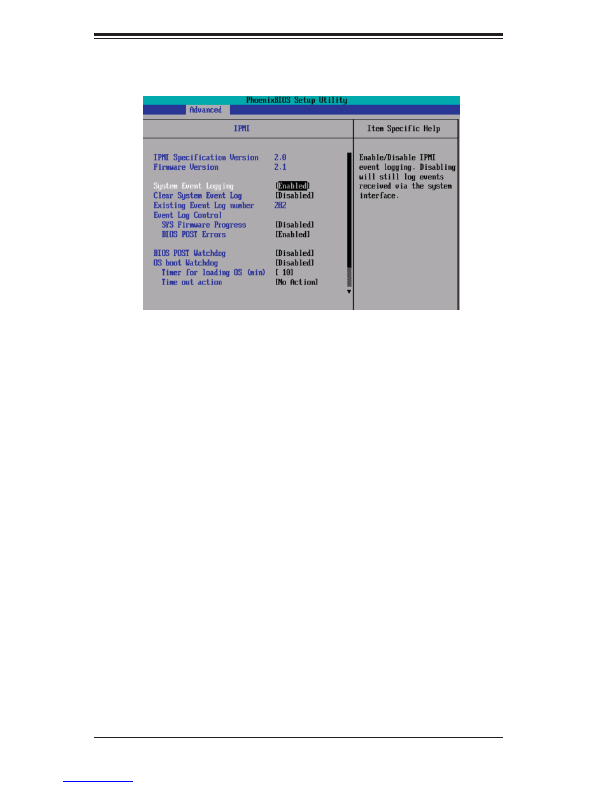
SUPERSERVER 5015B-MT User's Manual
XIPMI (Th e optio n is availabl e only whe n an IPMI ca rd is inst alled
in the system.)
IPMI Specifi cation Version:
This item displays the current IPMI Version.
Firm war e Versi on: This item displays the current Firmware Version.
System Event Logging
Select Enabled to enable IPMI Event Logging. When this function is set to Disabled,
the system will continue to log events received via system interface. The options
are Enabled and Disabled.
Clear S ystem Even t Loggi ng
Enabling t h i s f un c ti o n to f o rce the BI O S to c l e ar t h e syst em eve nt lo g s du r i ng t h e
next co ld boot . The opti ons are En abled an d Disabled.
Exis ting Event L og Numb er
This item displays the number of the existing event log.
Event Log Con trol
System Firmware Progress
Enabling this function to log POST progress. The options are Enabled and
Disabled.
BIOS POST Errors
Enabling this function to log POST errors. The options are Enabled and
Disabled.
BIOS POST Watch Dog
Set to Enabled to enable POST Watch Dog. The options are Enabled and Disabled.
7-20
Page 85
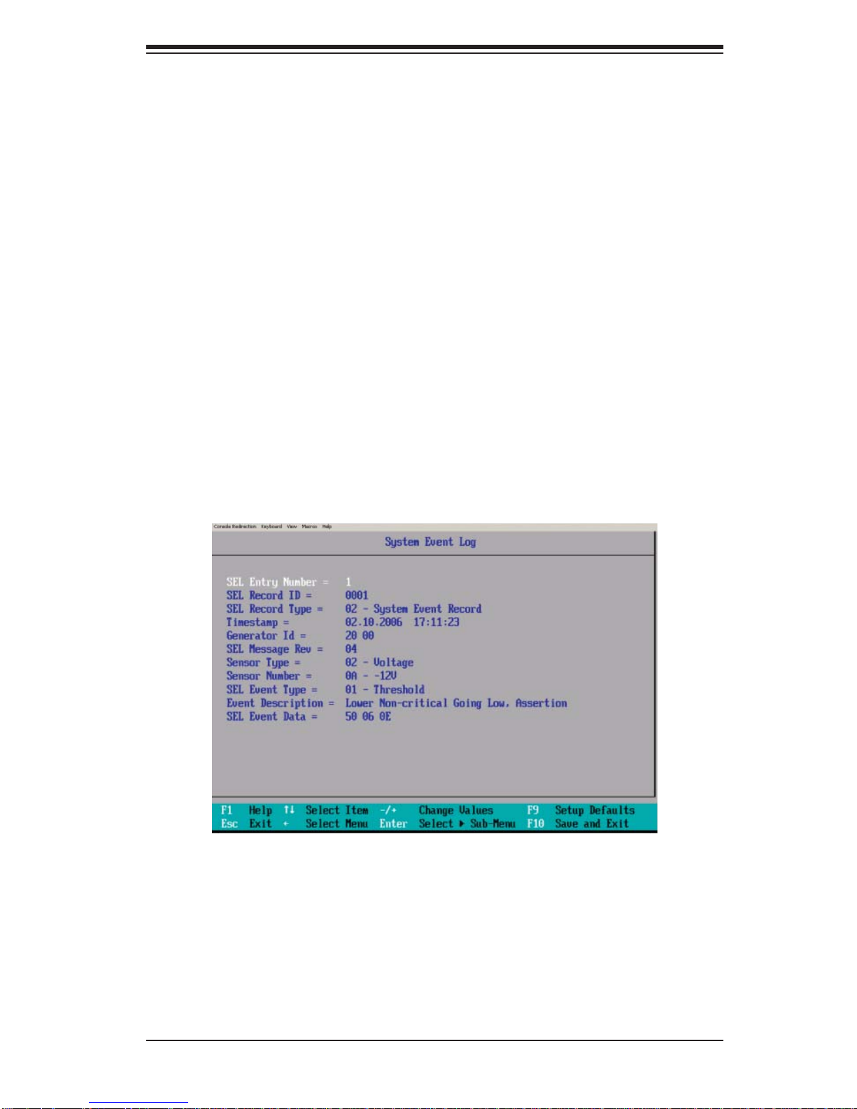
Chapter 7: BIOS
OS Boot Watch Dog
Set to Enabled to enable OS Boot Watch Dog. The options are Enabled and
Disabled.
Time r for Lo adin g OS (Min ute s)
This feature allows the user to set the time value (in minutes) for the previous
item: OS Boot Watch Dog by keying-in a desired number in the blank. The default
setting is 10 (minutes.) (Please ignore this option when OS Boot Watch Dog is
set to "Disabled".)
Time Out Option
This feature allows the user to determine what action to take in an event of a system
boot fail ure. The o ptions a re No Action, Reset, Power O ff a nd Power Cyc les.
XSys tem Event Lo g/Syst em Event Lo g (List Mod e)
These options display the System Event (SEL) Log and System Event (SEL) Log in
List Mode. Items include: SEL (System Event Log) Entry Number, SEL Record ID,
SEL Record Type, Time Stamp, Generator ID, SEL Message Revision, Sensor Type,
Sensor N umber, SEL Event Type, Event Descri ption, an d SEL Event Dat a.
7-21
Page 86
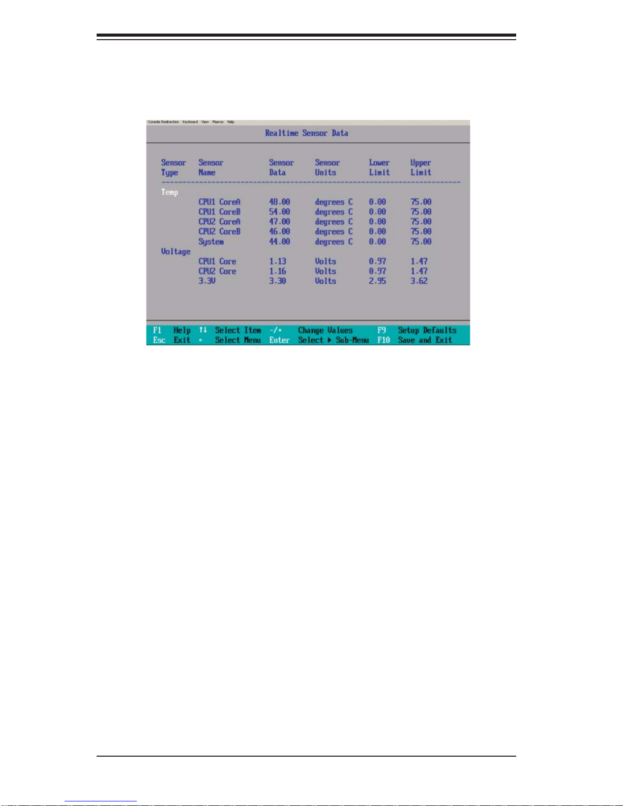
SUPERSERVER 5015B-MT User's Manual
XRe altim e Sensor Data
This feature display information from motherboard sensors, such as temperatures,
fan spee ds and vol tage s of vari ous co mpone nts.
7-22
Page 87
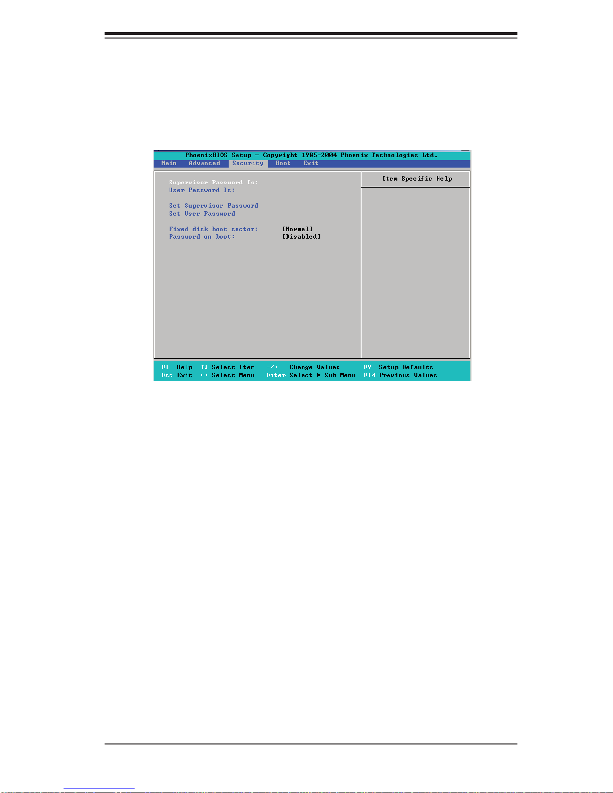
Chapter 7: BIOS
7-5 Security Settings
Choose Security from the Phoenix BIOS Setup Utility main menu with the arrow
keys. You should see the following display. Security setting options are displayed by
highlighting the setting using the arrow keys and pressing <Enter>. All Security BIOS
settings are described in this section.
Supervisor Password Is:
This item indicates if a supervisor password has been entered for the system.
Clear me ans such a passwo rd has not been use d and Set means a sup erviso r
passwor d has been en tered for t he system.
User Password Is:
This item i ndicates if a use r password has bee n entered for the sys tem. Clear
means suc h a pa ss wor d has n ot b ee n use d an d Set m ea ns a us er p as swor d ha s
been enter ed for th e system.
Set Supervisor Password
When the item "Set Supervisor Password" is highlighted, hit the <Enter> key.
When pro mpte d, t ype t he S upe r vi so r 's pas swo rd in t he dia lo gue b ox to set or to
change s uper viso r's pas sword, wh ich all ows acc ess to th e BIOS.
Set User Password
When the i tem "Set User Passwo rd" is highlighted, h it the <Enter> key. When
prompted, t ype t he user 's passwor d in the dial ogue box to set o r to chang e the
user 's passwor d, which a llows ac cess to t he system at bo ot-up.
7-23
Page 88

SUPERSERVER 5015B-MT User's Manual
Fixed Disk Boot Sector
Select Normal to enable the feature of Write-Protect to protect the boot sector on
the hard drives from virus intrusion.
Password on Boot
When set to Enabled, a user will need to key-in a password to enter the system at
system boot. The options are Enabled (password required) and Disabled (password
not required).
7-24
Page 89
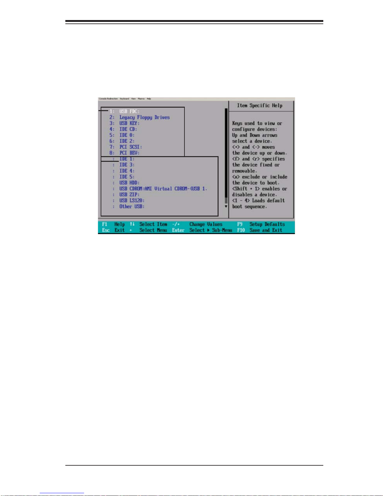
Chapter 7: BIOS
7-6 Boot Settings
Choose Boot from the Phoenix BIOS Setup Utility main menu with the arrow keys.
You should see the following display. See details on how to change the order and
specs of boot devices in the Item Specifi c Help window. All Boot BIOS settings are
described in this section.
Boot List
Candidate
List
Boot Priority Order/Excluded from Boot Orders
The devic es incl uded in the b oot list se ction (above) are boot able devic es liste d
in the sequence of boot order as specifi ed. The boot functions for the devices
includ ed in the c andidate li st (above) are currently d isabled . Use a <+> key or a
<-> key to move th e devi c e u p or d ow n. Us e t he < f> key or the <r > key to sp ec i fy
the type of an USB device, either fi xed or removable. You can select one item from
the boot l ist and hi t the <x > key to remove it f rom the l ist of bo otable d evice s (to
make its res ource availabl e for other boota ble devices). Subsequ ently, you ca n
selec t an item fro m the cand idate list and hi t the <x> key to re move it from th e
candidate list and put it in the boot list. This item will then become a bootable
device. S ee detai ls on how to c hange th e prio rit y of boot or der of devi ces in th e
"Item Specifi c Help" window.
7-25
Page 90
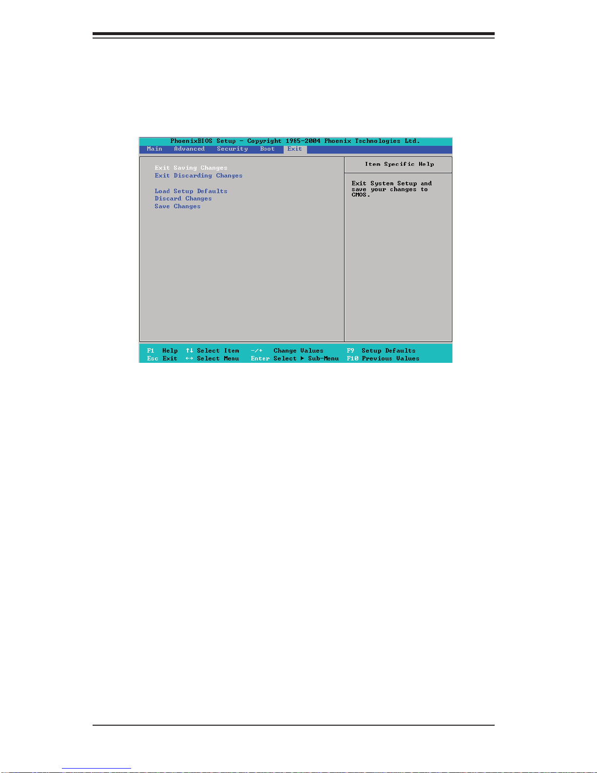
SUPERSERVER 5015B-MT User's Manual
7-7 Exit
Choose E x it fr om th e Pho enix B IO S Setup U til it y mai n menu w ith t he ar ro w keys.
You shou ld see the f ollowin g display. All Ex it BIOS set tings a re descr ibed in t his
section.
Exit Saving Changes
Highlight this item and hit <Enter> to save any changes you made and to exit the
BIOS Setup utility.
Exit Discarding Changes
Highlight this item and hit <Enter> to exit the BIOS Setup utility without saving any
changes you may have made.
Load Setup Defaults
Highlight this item and hit <Enter> to load the default settings for all items in the
BIOS Setup. These are the safest settings to use.
Discard Changes
Highlight this item and hit <Enter> to discard (cancel) any changes you made. You
will remain in the Setup utility.
Save Changes
Highlight this item and hit <Enter> to save any changes you made. You will remain
in the Setup utility.
7-26
Page 91

Appendix A: BIOS POST Messages
Appendix A
BIOS POST Messages
During the Power-On Self-Test (POST), the BIOS will check for problems. If a
problem is found, the BIOS will activate an alarm, turn on LED indicators or display
a message as listed below.
Failure Fixed Disk
Fixed disk is not working or not confi gured properly. Check to see if fi xed disk is at-
tached properly. Run Setup. Find out if the fi xed-disk type is correctly identifi ed.
Stuck key
Stuck key on keyboard.
Keyboard error
Keyboard not working.
Keyboard Controller Failed
Keyboard controller failed test. May require replacing keyboard controller.
Keyboard locked - Unlock key switch
Unlock the system to proceed.
Monitor type does not match CMOS - Run SETUP
Monitor type not correctly identifi ed in Setup
Shadow Ram Failed at offset: nnnn
Shadow RAM failed at offset nnnn of the 6 4k block at whi ch the error was d etected.
System RAM Failed at offset: nnnn
System RAM failed at offset nnnn of i n the 64 k block at w hich t he erro r was detected.
Extended RAM Failed at offset: nnnn
Extended memory not working or not confi gured properly at offset nnnn.
System battery is dead - Replace and run SETUP
The CM OS c lo c k bat te ry indic at or s how s th e bat te r y i s de ad. Rep lac e t he b at te r y
and run Setup to reconfi gure the system.
A-1
Page 92

SUPERSERVER 5015B-MT User's Manual
System CMOS checksum bad - Default confi guration used
System CMOS has been corrupted or modifi ed incorrectly, perhaps by an applica-
tion program that changes data stored in CMOS. The BIOS installed Default Setup
Values. If you do no t want t h e se va lu e s, e nte r S etu p an d e nter yo u r ow n val ue s . If
the error persists, check the system battery or contact your dealer.
System timer error
The timer test failed. Requires repair of system board.
Real time clock error
Real-Time Clock fails BIOS hardware test. May require board repair.
Check date and time settings
BIOS fou nd da te or ti me ou t of ra nge a nd re set t he Rea l -Time Clo ck . May re qui re
setting legal date (1991-2099).
Previous boot incomplete - Default confi guration used
Previous POST did not complete successfully. POST loads default values and offers
to run Setup. If the failure was caused by incorrect values and they are not corrected,
the next boot will likely fail. On systems with control of wait states, improper Setup
settings can also terminate POST and cause this error on the next boot. Run Setup
and veri f y th at th e wait st ate co nfi guratio n is c or r ec t. T hi s er ro r is c le are d th e nex t
time the system is booted.
Memory Size found by POST differed from CMOS
Memory size found by POST differed from CMOS.
Diskette drive A error
Diskette drive B error
Drive A : or B: is p re s ent b ut f ai ls t he B I OS P O ST di sket te te st s. C he c k to s ee t hat
the drive is defi ned with the proper diskette type in Setup and that the diskette drive
is attached correctly.
Incorrect Drive A type - run SETUP
Type of fl oppy drive A: not correctly identifi ed in Setup.
Incorrect Drive B type - run SETUP
Type of fl oppy drive B: not correctly identifi ed in Setup.
A-2
Page 93

Appendix A: BIOS POST Messages
System cache error - Cache disabled
RAM cache failed and BIOS disabled the cache. On older boards, check the cache
jumper s. You may have to replace t he cac he. See your d ealer. A disable d cach e
slows system performance considerably.
CPU ID:
CPU socket number for Multi-Processor error.
EISA CMOS not writeable
ServerBIOS2 test error: Cannot write to EISA CMOS.
DMA Test Failed
ServerBIOS2 test error: Cannot write to extended DMA (Direct Memory
Access) registers.
Software NMI Failed
ServerBIOS2 test error: Cannot generate software NMI (Non-Maskable Interrupt).
Fail-Safe Timer NMI Failed
ServerBIOS2 test error: Fail-Safe Timer takes too long.
Device Address Confl ict
Address confl ict for specifi ed device.
Allocation Error for: device
Run ISA or EIS A C on fi guration U ti li t y to r es o lve re s ou rc e c o n fl ict for the sp e ci fi ed
device.
CD ROM Drive
CD ROM Drive identifi ed.
Entering SETUP ...
Starting Setup program
Failing Bits: nnnn
The hex number nnnn is a map of the bits at the RAM address which failed the memory
test. Each 1 (one) in the map indicates a failed bit. See errors 230, 231, or 232 above
for offset address of the failure in System, Extended, or Shadow memory.
A-3
Page 94

SUPERSERVER 5015B-MT User's Manual
Fixed Disk n
Fixed disk n (0-3) identifi ed.
Invalid System Confi guration Data
Problem with NVRAM (CMOS) data.
I/O device IRQ confl ict
I/O device IRQ confl ict error.
PS/2 Mouse Boot Summary Screen:
PS/2 Mouse installed.
nnnn kB Extended RAM Passed
Where nnnn is the amount of RAM in kilobytes successfully tested.
nnnn Cache SRAM Passed
Where nnnn is the amount of system cache in kilobytes successfully tested.
nnnn kB Shadow RAM Passed
Where nnnn is the amount of shadow RAM in kilobytes successfully tested.
nnnn kB System RAM Passed
Where nnnn is the amount of system RAM in kilobytes successfully tested.
One or m ore I2O B l o c k S t o r a ge Devices wer e exc l u ded fro m the Se t u p Bo o t
Menu
There was n ot en ou gh r oo m in t he I P L ta bl e to di sp lay al l ins ta ll ed I 2O b lo c k-st orage devices.
Operating system not found
Operating system cannot be located on either drive A: or drive C:. Enter Setup and
see if fi xed disk and drive A: are properly identifi ed.
Parity Check 1 nnnn
Parity error found in the system bus. BIOS attempts to locate the address and
display it on the screen. If it cannot locate the address, it displays ????. Parity is a
method f or ch eck ing er ro rs in b inar y d ata. A p ari ty e rr or ind ica tes that s ome d ata
has been corrupted.
A-4
Page 95

Appendix A: BIOS POST Messages
Parity Check 2 nnnn
Parity error found in the I/O bus. BIOS attempts to locate the address and display it
on the screen. If it cannot locate the address, it displays ????.
Press <F1> to resume, <F2> to Setup, <F3> for previous
Displayed after any recoverable error message. Press <F1 > to start the boot process
or <F2> to enter Setup and change the settings. Press <F3> to display the previous
screen (usually an initialization error of an Option ROM, i.e. , an add-on card). Write
down and follow the information shown on the screen.
Press <F2> to enter Setup
Optional message displayed during POST. Can be turned off in Setup.
PS/2 Mouse:
PS/2 mouse identifi ed.
Run the I2O Confi guration Utility
One or mo r e unc l aim e d bl oc k s tor a ge d evices have the C o nfi guration Request bit
set in the LCT. Run an I2O Confi guration Utility (e.g. the SAC utility).
System BIOS shadowed
System BIOS copied to shadow RAM.
UMB upper limit segment address: nnnn
Display s the addre ss nnnn of t he uppe r limit of Upper Memo ry Blocks, indic ating rele ased segm ents of the B IOS whic h can be r eclaime d by a virt ual memo ry
manager.
Video BIOS shadowed
Video BIOS successfully copied to shadow RAM.
A-5
Page 96

SUPERSERVER 5015B-MT User's Manual
Notes
A-6
Page 97

Appendix B: BIOS POST Codes
Appendix B
BIOS POST Codes
This section lists the POST (Power On Self T est) codes for the Phoenix BIOS. POST
codes are divided into two categories: recoverable and terminal.
Recoverable PO ST Errors
When a re coverable t ype of er ror occu rs during P OST, the BIO S will displ ay an
POST co de that d esc ribe s the p robl em. The B IOS m ay also is sue on e of the fo llowing beep codes:
1 long and t wo sh or t beeps - v ideo c onfi guration error
1 conti nuous l ong bee p - overhe at (Overhe at LED wil l be on)
1 long bee p and 1 sho rt p ause - mem or y not detec ted
Ter minal POST Errors
If a terminal typ e of error occurs, the BIOS will shut down the system. Before
doing so, BI O S w il l write the error to po rt 80 h, attempt to ini ti al ize v i de o an d w r i te
the er ror in th e top lef t co rner o f the sc reen.
The foll owing is a l ist of co des that m ay be writ ten to p or t 80h.
POST Code Description
02h Verify Real Mode
03h Disable Non-Maskable Interrupt (NMI)
04h Get CPU type
06h Initialize system hardware
07h Disable shadow and execute code from the ROM.
08h Initialize chipset with initial POST values
09h Set IN POST fl ag
0Ah Initialize CPU registers
0Bh Enable CPU cache
0Ch Initialize caches to initial POST values
0Eh Initialize I/O component
0Fh Initialize the local bus IDE
10h Initialize Power Management
11h Load alternate registers with initial POST values
12h Restore CPU control word during warm boot
13h Initialize PCI Bus Mastering devices
14h Initialize keyboard controller
16h 1-2-2-3 BIOS ROM checksum
17h Initialize cache before memory Auto size
B-1
Page 98

SUPERSERVER 5015B-MT User's Manual
POST Code Description
18h 8254 timer initialization
1Ah 8237 DMA controller initialization
1Ch Reset Programmable Interrupt Controller
20h 1-3-1-1 Test DRAM refresh
22h 1-3-1-3 Test 8742 Keyboard Controller
24h Set ES segment register to 4 GB
28h Auto size DRAM
29h Initialize POST Memory Manager
2Ah Clear 512 kB base RAM
2Ch 1-3-4-1 RAM failure on address line xxxx*
2Eh 1-3-4-3 RAM failure on data bits xxxx* of low byte of
memory bus
2Fh Enable cache before system BIOS shadow
32h Test CPU bus-clock frequency
33h Initialize Phoenix Dispatch Manager
36h Warm start shut down
38h Shadow system BIOS ROM
3Ah Auto size cache
3Ch Advanced confi guration of chipset registers
3Dh Load alternate registers with CMOS values
41h Initialize extended memory for RomPilot
42h Initialize interrupt vectors
45h POST device initialization
46h 2-1-2-3 Check ROM copyright notice
47h Initialize I20 support
48h Check video confi guration against CMOS
49h Initialize PCI bus and devices
4Ah Initialize all video adapters in system
4Bh QuietBoot start (optional)
4Ch Shadow video BIOS ROM
4Eh Display BIOS copyright notice
4Fh Initialize MultiBoot
50h Display CPU type and speed
51h Initialize EISA board
52h Test keyboard
54h Set key click if enabled
55h Enable USB devices
58h 2-2-3-1 Test for unexpected interrupts
59h Initialize POST display service
5Ah Display prompt “Press F2 to enter SETUP”
5Bh Disable CPU cache
B-2
Page 99

Appendix B: BIOS POST Codes
POST Code Description
5Ch Test RAM between 512 and 640 kB
60h Test extended memory
62h Test extended memory address lines
64h Jump to UserPatch1
66h Confi gure advanced cache registers
67h Initialize Multi Processor APIC
68h Enable external and CPU caches
69h Setup System Management Mode (SMM) area
6Ah Display external L2 cache size
6Bh Load custom defaults (optional)
6Ch Display shadow-area message
6Eh Display possible high address for UMB recovery
70h Display error messages
72h Check for confi guration errors
76h Check for keyboard errors
7Ch Set up hardware interrupt vectors
7Dh Initialize Intelligent System Monitoring
7Eh Initialize coprocessor if present
80h Disable onboard Super I/O ports and IRQs
81h Late POST device initialization
82h Detect and install external RS232 ports
83h Confi gure non-MCD IDE controllers
84h Detect and install external parallel ports
85h Initialize PC-compatible PnP ISA devices
86h Re-initialize onboard I/O ports.
87h Confi gure Motherboard Confi gurable Devices
(optional)
88h Initialize BIOS Data Area
89h Enable Non-Maskable Interrupts (NMIs)
8Ah Initialize Extended BIOS Data Area
8Bh Test and initialize PS/2 mouse
8Ch Initialize fl oppy controller
8Fh Determine number of ATA drives (optional)
90h Initialize hard-disk controllers
91h Initialize local-bus hard-disk controllers
92h Jump to UserPatch2
93h Build MPTABLE for multi-processor boards
95h Install CD ROM for boot
96h Clear huge ES segment register
97h Fix up Multi Processor table
98h 1-2 Search for option ROMs. One long, two short
beeps on checksum failure
B-3
Page 100

SUPERSERVER 5015B-MT User's Manual
POST Code Description
99h Check for SMART Drive (optional)
9Ah Shadow option ROMs
9Ch Set up Power Management
9Dh Initialize security engine (optional)
9Eh Enable hardware interrupts
9Fh Determine number of ATA and SCSI drives
A0h Set time of day
A2h Check key lock
A4h Initialize typematic rate
A8h Erase F2 prompt
AAh Scan for F2 key stroke
ACh Enter SETUP
AEh Clear Boot fl ag
B0h Check for errors
B1h Inform RomPilot about the end of POST.
B2h POST done - prepare to boot operating system
B4h 1 One short beep before boot
B5h Terminate QuietBoot (optional)
B6h Check password (optional)
B7h Initialize ACPI BIOS
B9h Prepare Boot
BAh Initialize SMBIOS
BBh Initialize PnP Option ROMs
BCh Clear parity checkers
BDh Display MultiBoot menu
BEh Clear screen (optional)
BFh Check virus and backup reminders
C0h Try to boot with INT 19
C1h Initialize POST Error Manager (PEM)
C2h Initialize error logging
C3h Initialize error display function
C4h Initialize system error handler
C5h PnPnd dual CMOS (optional)
C6h Initialize Note dock (optional)
C7h Initialize Note dock late
C8h Force check (optional)
C9h Extended checksum (optional)
CAh Redirect Int 15h to enable remote keyboard
CBh Redirect Int 13h to Memory Technologies
Devices such as ROM, RAM, PCMCIA, and serial disk
CCh Redirect Int 10h to enable remote serial video
B-4
 Loading...