

Supero SuperServer 5011H, SuperServer 5011E User Manual
®
SUPER
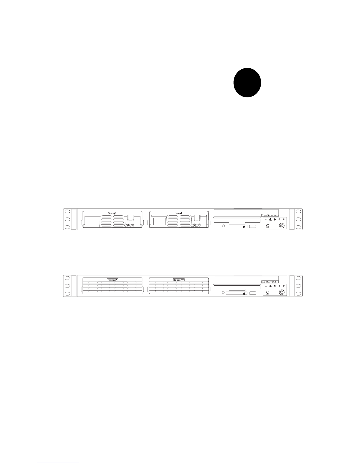
SuperServer 5011H
SuperServer 5011E
SUPERSERVER 5011H/5011E
USER’S MANUAL
Revision 1.0a
S
UPERMICR
R
S
UPERMICR
R

The information in this User’s Manual has been carefully reviewed and is believed to be
accurate. The vendor assumes no responsibility for any inaccuracies that may be
contained in this document, makes no commitment to update or to keep current the
information in this manual, or to notify any person or organization of the updates.
Please
Note: For the most up-to-date version of this manual, please see our
web site at www.supermicro.com.
SUPERMICRO COMPUTER reserves the right to make changes to the product described in
this manual at any time and without notice. This product, including software, if any, and
documentation may not, in whole or in part, be copied, photocopied, reproduced, translated
or reduced to any medium or machine without prior written consent.
IN NO EVENT WILL SUPERMICRO COMPUTER BE LIABLE FOR DIRECT, INDIRECT,
SPECIAL, INCIDENTAL, SPECULATIVE OR CONSEQUENTIAL DAMAGES ARISING FROM
THE USE OR INABILITY TO USE THIS PRODUCT OR DOCUMENTATION, EVEN IF
ADVISED OF THE POSSIBILITY OF SUCH DAMAGES. IN PARTICULAR, THE VENDOR
SHALL NOT HAVE LIABILITY FOR ANY HARDWARE, SOFTWARE, OR DATA STORED
OR USED WITH THE PRODUCT, INCLUDING THE COSTS OF REPAIRING, REPLACING,
INTEGRATING, INSTALLING OR RECOVERING SUCH HARDWARE, SOFTWARE, OR
DATA.
Any disputes arising between manufacturer and customer shall be governed by the laws of
Santa Clara County in the State of California, USA. The State of California, County of
Santa Clara shall be the exclusive venue for the resolution of any such disputes.
Supermicro's total liability for all claims will not exceed the price paid for the hardware
product.
Unless you request and receive written permission from SUPER MICRO COMPUTER, you
may not copy any part of this document.
Information in this document is subject to change without notice. Other products and
companies referred to herein are trademarks or registered trademarks of their respective
companies or mark holders.
Copyright © 2001 by SUPER MICRO COMPUTER INC.
All rights reserved.
Printed in the United States of America.

Preface
About This Manual
This manual is written for professional system integrators and PC technicians. It provides information for the installation and use of the SuperServer 5011H/5011E. Installation and maintainance should be performed by
experienced technicians only.
The SuperServer 5011H/5011E is a high-end single processor 1U rackmount
server based on the SC810 1U rackmount server chassis and either the
Super P3TSSR (for the 5011H) or the P3TSSE (for the 5011E) mainboard.
The P3TSSR/P3TSSE mainboard supports single Intel® PentiumTM III FCPGA
500 MHz-1.26+ GHz processors and CeleronTM FCPGA/PPGA 600-850 processors and up to 512 MB SDRAM main memory.
Manual Organization
Chapter 1: Introduction
The first chapter provides a checklist of the main components included with
the server system and describes the main features of the Super P3TSSR
and P3TSSE mainboards and the SC810 chassis.
Chapter 2: Server Installation
This chapter describes the steps necessary to install the SuperServer
5011H/5011E into a rack and check out the server configuration prior to
powering up the system. If your server was ordered without the processor and memory components, this chapter will refer you to the appropriate
sections of the manual for their installation.
Chapter 3: System Interface
Refer to this chapter for details on the system interface, which includes the
functions and information provided by the control panel on the chassis as
well as other LEDs located throughout the system.
iii
Preface

SUPERSERVER 5011H/5011E Manual
iv
Chapter 4: System Safety
You should thoroughly familiarize yourself with this chapter for a general
overview of safety precautions that should be followed when installing and
servicing the SuperServer 5011H/5011E.
Chapter 5: Advanced Motherboard Setup
Chapter 5 provides detailed information on the P3TSSR and P3TSSE
motherboards, including the locations and functions of connectors, headers, jumpers, DIP switches and IRQs. Refer to this chapter when adding or
removing processors or main memory and when reconfiguring the
motherboard.
Chapter 6: Advanced Chassis Setup
Refer to Chapter 6 for detailed information on the SC810 1U rackmount
server chassis. You should follow the procedures given in this chapter
when installing, removing or reconfiguring SCSI or peripheral drives and
when replacing system power supply units and cooling fans.
Chapter 7: BIOS
The BIOS chapter includes an introduction to BIOS and provides detailed
information on running the CMOS Setup Utility.
Appendix A: BIOS Error Beep Codes and Messages
Appendix B: Post Diagnostic Error Messages
Appendix C: List of Figures
Appendix D: System Specifications
v
Manu al Organization
Introduction
Ch
p
1
Ins ta llatio n System
Interface
System
Sa fety
Motherboard
De t a ils
Chassis
De t a ils
BIOS and
Setup Routine
Ch
p
3Ch
p
2
Ch
p
5
Ch
p
4
Ch
p
6
Appendices
- Overview
- Chassis
Features
- Mainboard
Features
- Contacting
Supermicro
- Overview
- Precautions
- Ra ck
Installation
- Se tup
- Overview
- Control Panel
Butto ns
- Control Panel
LEDs
- SC S I LE D s
- Power Supply
Switch
- Motherboard
LEDs
- Sta tic Sa fe ty
- MB Ins tallation
- Cables
- I/O P orts
- CP U
Installation
- Me mo ry
- PC I C a rds
- MB Layout
- Connectors
- DIP Switches
- Jumpers
- Drive Conn.
- IRQ s
- Sta tic Sa fe ty
- Control Panel
- System F ans
- Drive B ay Ins t.
- Power Supply
Ch
p
7A
pp
. A/B /C/D
- Introduction
- BIOS Features
- Running
C MO S S etu p
- Electrical
S a f ety
- General
S a f ety
- ES D S a fety
- BIOS E rro r
Beep Codes
- Post Diag.
Error Messages
- List of Figures
- System S pecs
Preface

SUPERSERVER 5011H/5011E Manual
vi
Table of Contents
Preface
About This Manual ...................................................................................................... iii
Manual Organization ................................................................................................... iii
Manual Organization (Flowchart)............................................................................. v
Chapter 1: Introduction to the SuperServer 5011H/5011E
1-1 Overview ......................................................................................................... 1-1
1-2 Server Chassis Features.............................................................................. 1-2
1-3 Mainboard Features ....................................................................................... 1-4
1-4 Contacting Supermicro .................................................................................. 1-7
Chapter 2: Server Installation
2-1 Overview ......................................................................................................... 2-1
2-2 Unpacking the SuperServer 5011H/5011E ................................................. 2-1
2-3 Preparing for Setup ....................................................................................... 2-1
Choosing a Setup Location .................................................................... 2-2
Rack Precautions ..................................................................................... 2-2
Server Precautions.................................................................................. 2-2
2- 4 Installing the SuperServer 5011H/5011E into a Rack .............................. 2-3
Identifying the Sections of the Rack Rails .......................................... 2-3
Installing the Chassis Rails ..................................................................... 2 - 4
Installing the Rack Rails .......................................................................... 2 - 4
Installing the Server into the Rack ........................................................ 2 -5
Installing the Server into a Telco Rack ................................................ 2 -6
2- 5 Checking the Motherboard Setup ................................................................ 2-7
2-6 Checking the Drive Bay Setup ................................................................... 2-10
Chapter 3: System Interface
3-1 Overview ......................................................................................................... 3-1
3- 2 Control Panel Buttons .................................................................................... 3-1
Reset .......................................................................................................... 3-1
Power ........................................................................................................ 3-1
3-3 Control Panel LEDs ........................................................................................ 3-2
Overheat ................................................................................................... 3-2
NIC2 ............................................................................................................ 3-2
NIC1 ............................................................................................................ 3-2
HDD ............................................................................................................ 3-2

Power ........................................................................................................ 3-3
3- 4 SCSI Drive Carrier LEDs (5011H) ................................................................ 3-3
3-5 Power Supply Switch.................................................................................... 3-3
3- 6 Motherboard LEDs .......................................................................................... 3-3
Chapter 4: System Safety
4-1 Electrical Safety Precautions ........................................................................ 4-1
4-2 General Safety Precautions .......................................................................... 4-2
4- 3 ESD Precautions .............................................................................................. 4-3
Chapter 5: Advanced Motherboard Setup
5-1 Handling the P3TSSR/P3TSSE Motherboard................................................ 5-1
5- 2 Motherboard Installation ................................................................................. 5-2
5-3 Connecting Cables .......................................................................................... 5 - 3
Connecting Data Cables .......................................................................... 5- 3
Connecting Power Cables....................................................................... 5-3
Connecting the Control Panel ................................................................. 5 - 4
5 - 4 I/ O Po rt s ............................................................................................................ 5 - 5
5-5 Installing Processors ...................................................................................... 5-5
5- 6 Installing Memory ............................................................................................. 5-7
5- 7 Adding PCI Cards ............................................................................................ 5 -8
P3TSSR Layout and Quick Reference .......................................... 5-10,11
P3TSSE Layout and Quick Reference .......................................... 5-12,13
5-8 Connector Definitions ................................................................................... 5-14
Power Supply Connector ..................................................................... 5-14
Infrared Connector ................................................................................. 5-14
PWR_ON .................................................................................................. 5-14
Reset ........................................................................................................ 5-15
Overheat LED ......................................................................................... 5-15
NIC1 LED ................................................................................................. 5-15
NIC2 LED ................................................................................................. 5-15
HDD LED ................................................................................................... 5-16
Power LED ............................................................................................... 5-16
Universal Serial Bus (USB) .................................................................. 5-16
Fan Headers ........................................................................................... 5-17
Serial Ports ............................................................................................. 5-17
ATX PS/2 Keyboard and Mouse Ports................................................ 5-18
LAN1/LAN2 Ports................................................................................... 5-18
Wake-On-Ring ........................................................................................ 5-18
Wake-On-LAN ........................................................................................ 5-19
vii
Table of Contents

SUPERSERVER 5011H/5011E Manual
viii
Chassis Intrusion .................................................................................... 5-19
5- 9 Jumper Settings ............................................................................................. 5-20
Explanation of Jumpers ......................................................................... 5-20
Front Side Bus Speed ........................................................................... 5-20
CMOS Clear.............................................................................................. 5-21
Speaker Enable/Disable ......................................................................... 5-21
LAN1/LAN2 Enable/Disable ................................................................... 5-21
Keyboard Wake-Up................................................................................. 5-21
LVD Channel A SCSI Termination Enable/Disable(5011H)............... 5-22
LVD Channel B SCSI Termination Enable/Disable(5011H) ............... 5-22
SCSI Enable/Disable(5011H) ................................................................. 5-22
Watchdog Reset ..................................................................................... 5-22
5-10 Floppy/Hard Disk and SCSI Connections .................................................. 5-23
Floppy Connector ................................................................................... 5-23
IDE Connectors ...................................................................................... 5-23
Ultra160 SCSI Connectors ..................................................................... 5-24
Chapter 6: Advanced Chassis Setup
6-1 Static-Sensitive Devices ................................................................................ 6-1
6-2 Control Panel .................................................................................................... 6-2
6-3 System Fans .................................................................................................... 6-3
System Fan Failure .................................................................................. 6-3
Replacing System Cooling Fans ............................................................ 6-3
6- 4 Drive Bay Installation/Removal ...................................................................... 6-4
Accessing the Drive Bays ..................................................................... 6-4
SCSI Drive Installation............................................................................. 6-5
IDE Drive Installation................................................................................ 6-7
CD-ROM and Floppy Drive Installation ................................................. 6-8
6-5 Power Supply .................................................................................................. 6-9
Power Supply Failure ............................................................................. 6-9
Replacing the Power Supply ................................................................. 6-9
Chapter 7: BIOS
7- 1 Introduction....................................................................................................... 7-1
7- 2 BIOS Features.................................................................................................. 7-2
7- 3 Running Setup.................................................................................................. 7 -2
The Main BIOS Setup Menu .................................................................... 7-3
7-4 Advanced Chipset Setup ............................................................................... 7-4
Health Monitor Features .......................................................................... 7- 4
Super I/O Configuration ........................................................................... 7 -6

Table of Contents
ix
IDE Configuration ...................................................................................... 7-8
Floppy Configuration .............................................................................. 7-11
Boot Settings Configuration .................................................................. 7-12
Event Log Configuration ........................................................................ 7-15
7- 5 Chipset Setup................................................................................................. 7-16
GMCH Configuration ............................................................................... 7-16
ICH2 Configuration .................................................................................. 7-20
7-6 PCI PnP Setup ................................................................................................ 7-23
7-7 Power Setup .................................................................................................. 7-27
7- 8 Boot Setup...................................................................................................... 7-33
Boot Device Priority ................................................................................7-33
Hard Disk Drives ..................................................................................... 7-34
Removable Devices ................................................................................ 7-34
ATAPI CD-ROM Drives ........................................................................... 7-34
7-9 Security Setup ............................................................................................... 7-35
Supervisor Password ............................................................................ 7-35
User Password ....................................................................................... 7-35
Change Supervisor Password ............................................................. 7-36
Change User Password ........................................................................ 7-36
Clear User Password ............................................................................ 7-36
Boot Sector Virus Protection ............................................................... 7-36
7-10 Exit Setup ....................................................................................................... 7-37
Exit Saving Changes .............................................................................. 7-37
Exit Discarding Changes ....................................................................... 7-37
Load Optimal Defaults............................................................................ 7-38
Load Fail Safe Defaults ......................................................................... 7-38
Discard Changes .................................................................................... 7-38
Appendices:
Appendix A: BIOS Error Beep Codes and Messages ....................................... A - 1
Appendix B: AMIBIOS POST Checkpoint Codes ..................................................B-1
Appendix C: List of Figures .................................................................................... C-1
Appendix D: System Specifications ...................................................................... D-1

SUPERSERVER 5011H/5011E User's Manual
x
NOTES

Chapter 1
Introduction to the SuperServer 5011H/5011E
1-1 Overview
The Supermicro SuperServer 5011H/5011E is a high-end single processor,
1U rackmount server that features some of the most advanced technology
currently available. The SuperServer 5011H/5011E is comprised of two
main subsystems: the SC810 1U rackmount chassis and the P3TSSR (for
5011H) or P3TSSE (for 5011E) single 370-pin Pentium III FCPGA or Celeron
FCPGA/PPGA processor mainboard. Please refer to our web site for information on operating systems that have been certified for use with the
SuperServer 5011H/5011E. (www.supermicro.com)
In addition to the mainboard and chassis, various hardware components
may have been included with your SuperServer 5011H/5011E, as listed
below.
l One (1) 370-pin Pentium III FCPGA or one Celeron FCPGA/PPGA proces
sor*
l One CPU heat sink
l Up to 512 MB SDRAM (non-ECC supported, non-registered) main
memory
l One (1) 1.44" floppy drive
l One (1) slim CD-ROM drive
l One (1) SCA SCSI backplane (5011H only)
l Two (2) SCA SCSI drive carriers (5011H only)
l SCSI Accessories(5011H only):
One (1) internal 68-pin Ultra160 SCSI cable for SCA SCSI backplane
One (1) set of SCSI driver diskettes
One (1) SCSI manual
Chapter 1: Introduction
1-1

SUPERSERVER 5011H/5011E Manual
1-2
1-2 Server Chassis Features
The SuperServer 5011H/5011E is a high-end, scaleable 1U rackmount
server platform designed with today's most state-of-the-art features. The
following is a general outline of the main features of the SC810 chassis.
System Power
When configured as a SuperSever 5011H/5011E, the SC810 chassis includes a 200W power supply.
SCSI Subsystem (5011H only)
The SCSI subsystem on the 5011H supports two 80-pin SCA Ultra160 SCSI
hard drives. (Standard 1" drives are supported. SCA = Single Connection
Attachment.) The SCSI drives are connected to an SCA backplane that
provides power, bus termination and configuration settings. The SCSI
drives are also hot-swap units.
Control Panel
The SC810's control panel provides important system monitoring and control
information. LEDs indicate power on, network activity, hard disk drive activity and system overheat conditions. The control panel also includes a
main power button and a system reset button.
l One (1) 5V 32-bit, 33 MHz PCI slot riser card
l Rackmount hardware (with screws):
Two (2) rack rail assemblies
Six (6) brackets for mounting the rack rails in a rack/telco rack
l One (1) CD-ROM containing drivers and utilities:
Intel's® LANDesk Client Manager
LAN driver
SCSI driver (5011H only)
l SuperServer 5011H/5011E User's Manual
*
Type and number depends upon the configuration ordered.
1-3
Chapter 1: Introduction
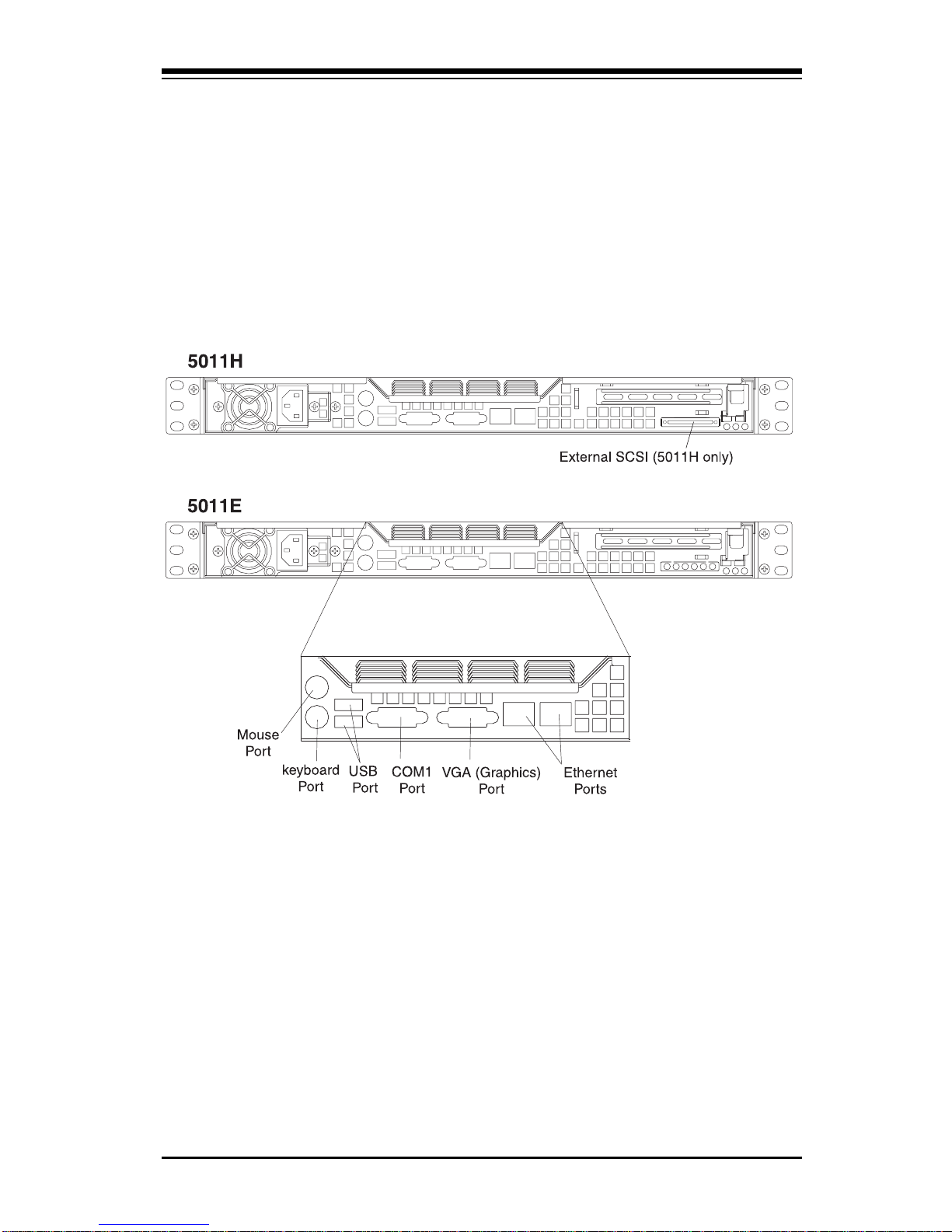
Rear I/O Panel
The SC810 is a 1U rackmount chassis. Its I/O panel provides one motherboard expansion slot, one COM port (another is internal), two USB ports
(5011H only), PS/2 mouse and keyboard ports, a graphics port and two
Ethernet ports. (See Figure 1-1.)
Cooling System
The SC810 chassis has an innovative cooling design that includes a 10-cm
blower system cooling (intake) fan and one optional 4-cm fan that can be
installed in the midsection of the chassis. The blower fan plugs into a
chassis fan header on the motherboard and operates at full rpm continuously. If it breaks down, the ambient air temperature inside the chassis will
rise and activate an overheat LED.
Figure 1-1. Rear I/O Panel

SUPERSERVER 5011H/5011E Manual
1-4
1-3 Mainboard Features
At the heart of the SuperServer 5010H/5010E lies the P3TSSR/P3TSSE, a
single processor motherboard designed to provide maximum performance.
Below are the main features of the P3TSSR/P3TSSE.
Chipset Overview
Intel’s 815E chipset is made up of three main components: the Graphics and
Memory Controller Hub (GMCH), the I/O Controller Hub (ICH) and the Firmware Hub (FWH). The GMCH integrates a 133/100/66 MHz system bus
controller, a 2D/3D graphics accelerator (AGP2x/4x) discrete graphics card,
a 133/100 MHz SDRAM controller and a high-speed hub architecture interface that communicates with the ICH. The ICH integrates a UDMA/100 controller, USB controllers and other I/O functions (see below). The FWH
stores both system and video BIOS and includes a Random Number Generator (RNG).
Graphics and Memory Controller Hub (GMCH)
The GMCH includes the host (CPU) interface, DRAM interface, ICH2 interface and 4xAGP interface for the 815E chipset. It contains advanced power
management logic and supports dual channels for DRAM. The AGP 2.0
interface supports 4x data transfers and operates at a peak bandwidth of
1066 MB/sec. The MCH host interface bus runs at 133/100/66 MHz.
I/O Controller Hub (ICH2)
The ICH2 I/O Controller Hub subsystem on the P3TSSR/P3TSSE integrates
many of the Input/Output functions of the 815E chipset, including UDMA/
100 Bus Master IDE controllers. It also provides the interface to the PCI Bus
and communicates with the MCH over a dedicated hub interface. In addition
to the UDMA/100 Bus Master IDE controllers, this powerful ICH2 also includes two USB controllers that offer 24 Mbps of bandwidth across three
ports. ICH2 also features an enhanced AC'97 interface that supports full
surround sound for the Dolby Digital Audio used on DVDs.
Firmware Hub (FWH)
The FWH is a component that brings added security and manageability to
the PC platform infrastructure. This device includes an integrated Random

1-5
Chapter 1: Introduction
Number Generator (RNG) for stronger encryption, digital signing and security protocols. The FWH stores the system BIOS and video BIOS to eliminate
a redundant nonvolatile memory component.
Processors
The P3TSSR/P3TSSE supports single 370-pin Pentium III FCPGA 600 MHz-
1.26 GHz and Celeron FCPGA/PPGA 300-700 MHz processors with Front
Side Bus Speeds of 133/100/66 MHz. Please refer to the support section
of our web site for a complete listing of supported processors (http://
www.supermicro.com/TechSupport.htm).
Memory
The P3TSSR/P3TSSE has three (3) 168-pin DIMM sockets that can support
up to 512 MB of unbuffered PC133 and PC100 SDRAM. Module sizes of
128MB, 256MB and 512MB may be used to populate the DIMM slots. The
DIMM slots are situated at a 25 degree angle to create a low profile and to
promote efficient airflow through the chassis.
Onboard SCSI (5011H only)
Onboard SCSI is provided with an Adaptec AIC-7899 SCSI controller chip,
which supports dual channel, Ultra160 SCSI at a burst throughput rate of
160 MB/sec for each channel. The P3TSSR provides two SCSI ports: one
internal 68-pin LVD Ultra160 connector (on Channel A) and one external/
internal (shared) 68-pin Ultra160 SCSI connector (channel B).
PCI Expansion Slots
The P3TSSR/P3TSSE has four 32-bit 33 MHz PCI slots available. One riser
card is included with the system for use with 32-bit PCI cards.
Network Interface Controllers (NIC)
The P3TSSR/P3TSSE supports two Network Interface controllers (NIC)
based on Intel's 82559 and 82562 chips. (For the 5011H server, which is
based on the P3TSSR mainboard, two 82559 Ethernet chips are included in
the system.)

SUPERSERVER 5011H/5011E Manual
1-6
Onboard Controllers/Ports
An onboard IDE controller supports one floppy drive and up to four UDMA/
100 hard drives or ATAPI devices. Onboard I/O ports include one COM port,
two USB ports, PS/2 mouse and keyboard ports, a video (Graphics) port
and two LAN (NIC) ports which back each other up in case one port loses
connection.
Other Features
Other onboard features that promote system health include eight voltage
monitors, a chassis intrusion header, auto-switching voltage regulators,
chassis and CPU overheat sensors, virus protection and BIOS rescue.

1-7
Chapter 1: Introduction
1-4 Contacting Supermicro
Headquarters
Address: Super Micro Computer, Inc.
980 Rock Ave.
San Jose, CA 95131 U.S.A.
Tel: +1 (408) 503-8000
Fax: +1 (408) 503-8008
E-mail: marketing@supermicro.com (General Information)
support@supermicro.com (Technical Support)
Web site: www.supermicro.com
European Office
Address: Super Micro Computer B.V.
Het Sterrenbeeld 28, 5215 ML,
's-Hertogenbosch, The Netherlands
Tel: +31 (0) 73-6400390
Fax: +31 (0) 73-6416525
E-mail: sales@supermicro.nl (General Information)
support@supermicro.nl (Technical Support)
rma@supermicro.nl (Customer Support)
Asia-Pacific
Address: 3F, #753 Chung-Cheng Road
Chung-Ho City, Taipei Hsien, Taiwan, R.O.C.
Tel: +886-(2) 8228-1366
Fax: +886-(2) 8221-2790
Web Site: www.supermicro.com.tw
Email: support@supermicro.com.tw
Technical Support:
Tel : 886-2-8228-1366, ext.132

SUPERSERVER 5011H/5011E Manual
1-8
NOTES

Chapter 2: Server Installation
2-1
Chapter 2
Server Installation
2-1 Overview
This chapter provides a quick setup checklist to get your SuperServer
5011H/5011E up and running. Following these steps in the order given
should enable you to have the system operational within a minimum amount
of time. This quick setup assumes that your SuperServer 5011H/5011E
system has come to you with the processor and memory preinstalled. If
your system is not already fully integrated with a motherboard, processor,
system memory etc., please turn to the chapter or section noted in each
step for details on installing specific components.
2-2 Unpacking the SuperServer 5011H/5011E
You should inspect the box the SuperServer 5011H/5011E was shipped in
and note if it was damaged in any way. If the server itself shows damage,
you should file a damage claim with the carrier who delivered it.
Decide on a suitable location for the rack unit that will hold the SuperServer
5011H/5011E. It should be situated in a clean, dust-free area that is well
ventilated. Avoid areas where heat, electrical noise and electromagnetic
fields are generated. You will also need it placed near a grounded power
outlet. Read the Rack and Server Precautions in the next section.
2-3 Preparing for Setup
The box the SuperServer 5011H/5011E was shipped in should include two
sets of rail assemblies, two rail mounting brackets and the mounting screws
you will need to install the system into the rack. Follow the steps in the
order given to complete the installation process in a minimum amount of time.
Please read this section in its entirety before you begin the installation
procedure outlined in the sections that follow.
2-2
SUPERSERVER 5011H/5011E Manual
Choosing a Setup Location
- Leave enough clearance in front of the rack to enable you to open
the front door completely (~25 inches).
- Leave approximately 30 inches of clearance in the back of the rack
to allow for sufficient airflow and ease in servicing.
Rack Precautions
- Ensure that the leveling jacks on the bottom of the rack are fully
extended to the floor with the full weight of the rack resting on them.
- In a single rack installation, stabilizers should be attached to the rack.
- In multiple rack installations, the racks should be coupled together.
- Always make sure the rack is stable before extending a component
from the rack.
- You should extend only one component at a time - extending two or
more simultaneously may cause the rack to become unstable.
Server Precautions
- Review the electrical and general safety precautions in Chapter 4.
- Determine the placement of each component in the rack
before
you
install the rails.
- Install the heaviest server components on the bottom of the rack
first, and then work up.
- Use a regulating uninterruptible power supply (UPS) to protect the
server from power surges, voltage spikes and to keep your
system operating in case of a power failure.
- Allow the power supply units and hot plug SCSI drives (5011H) to
cool before touching them.
- Always keep the rack's front door and all panels and components on
the servers closed when not servicing to maintain proper cooling.
! !
Warnings and Precautions!
Chapter 2: Server Installation
2-3
2-4 Installing the SuperServer 5011H/5011E into a
Rack
This section provides information on installing the SuperServer 5011H/5011E
into a rack unit. If the 5011H/5011E has already been mounted into a rack,
you can skip ahead to Sections 2-5 and 2-6. There are a variety of rack
units on the market, which may mean the assembly procedure will differ
slightly. The following is a guideline for installing the 5011H/5011E into a
rack with the rack rails provided with the system. You should also refer to
the installation instructions that came with the rack unit you are using.
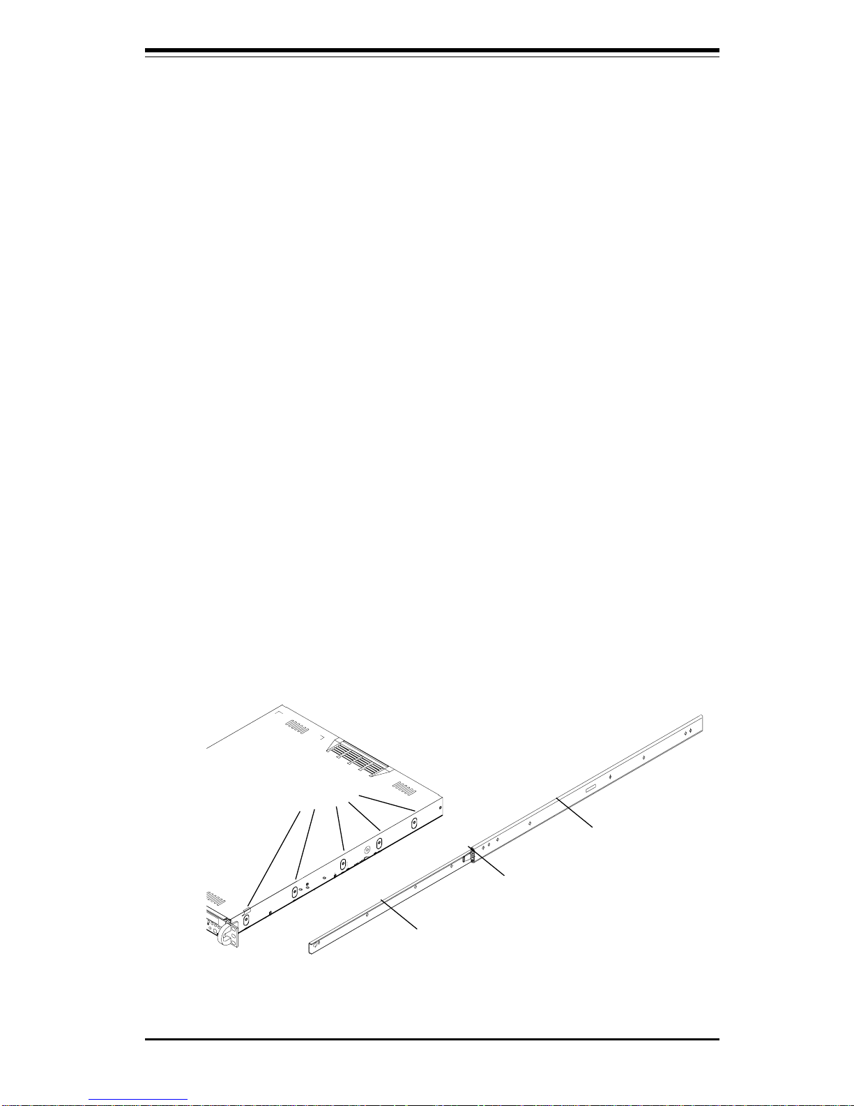
Identifying the Sections of the Rack Rails
You should have received two rack rail assemblies with the SuperServer
5011H/5011E. Each of these assemblies consist of two sections: an inner
fixed chassis rail that secures to the 5011H/5011E (A) and an outer fixed
rack rail that secures directly to the rack itself (B). A sliding rail guide
sandwiched between the two should remain attached to the fixed rack rail
(see Figure 2-1). The A and B rails must be detached from each other to
install.
To remove the fixed chassis rail (A), pull it out as far as possible - you
should hear a "click" sound as a locking tab emerges from inside the rail
assembly and locks the inner rail. Then depress the locking tab to pull the
inner rail completely out. Do this for both the left and right side rack rail
assemblies.
Figure 2-1. Identifying the Sections of the Rack Rails
Mounting Holes
A
Locking Tab
B
2-4
SUPERSERVER 5011H/5011E Manual
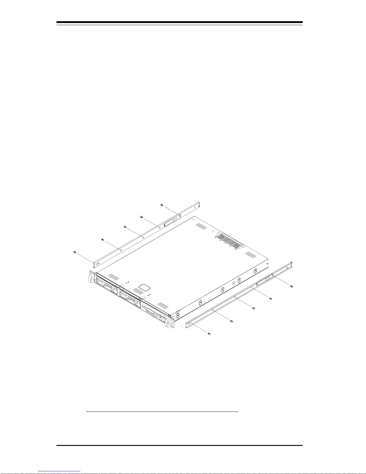
Installing the Chassis Rails
Position the fixed chassis rail sections you just removed along the side of
the 5011H/5011E chassis making sure the five screw holes line up. Note
that these two rails are left/right specific. Screw the rail securely to the
side of the chassis (see Figure 2-2). Repeat this procedure for the other
rail on the other side of the chassis. You will also need to attach the rail
brackets when installing into a telco rack.
Locking Tabs: As you have seen, both chassis rails have a locking tab,
which serves two functions. The first is to lock the server into place
when installed and pushed fully into the rack, which is its normal position.
Secondly, these tabs also lock the server in place when fully extended
from the rack. This prevents the server from coming completely out of
the rack when you pull it out for servicing.
Figure 2-2. Installing Chassis Rails
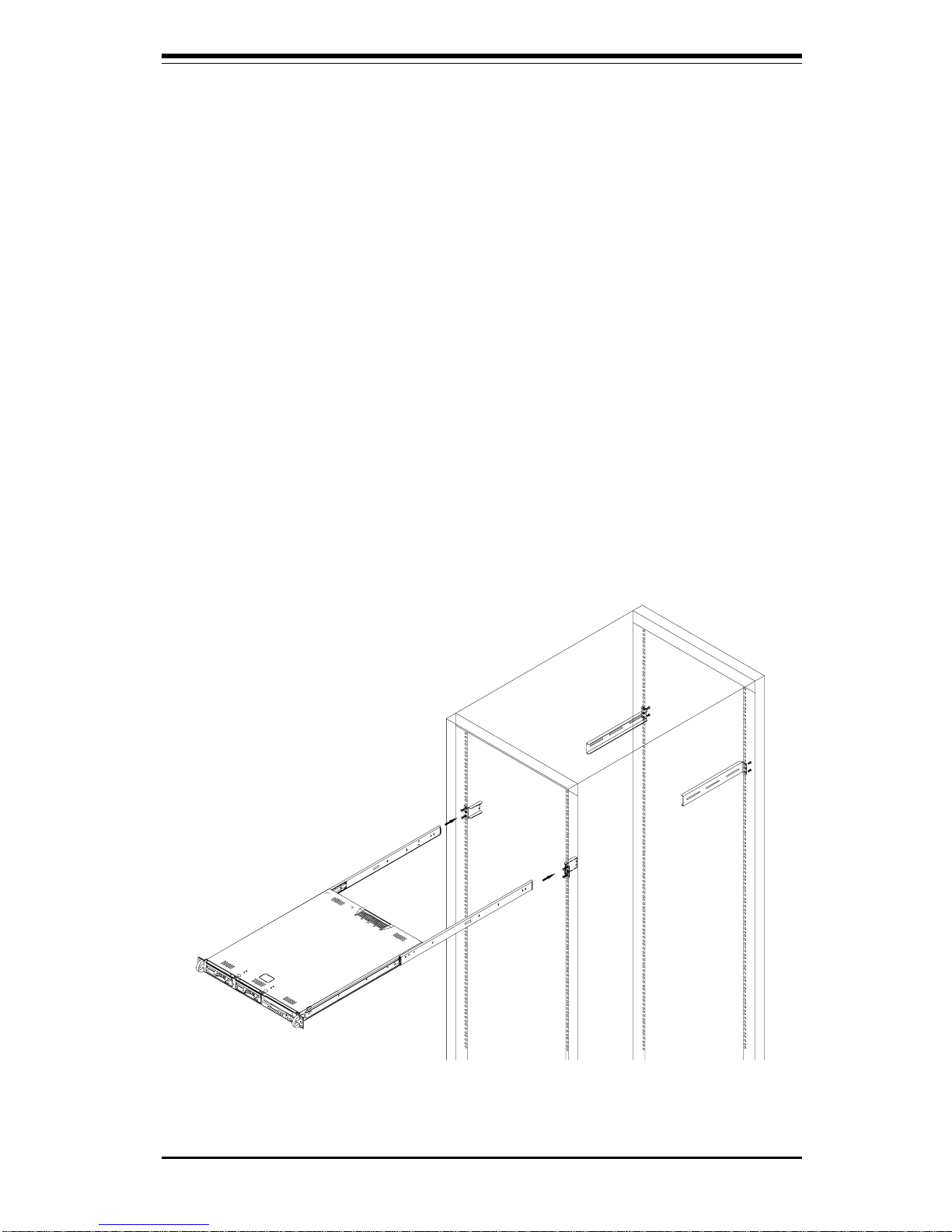
Installing the Rack Rails
Determine where you want to place the SuperServer 5011H/5011E in the
rack (see Rack and Server Precautions in Section 2-3). Position the fixed
rack rail/sliding rail guide assemblies at the desired location in the rack,
keeping the sliding rail guide facing the inside of the rack. Screw the
Chapter 2: Server Installation
2-5
Figure 2-3. Installing the Server into a Rack
Installing the Server into the Rack
You should now have rails attached to both the chassis and the rack
unit. The next step is to install the server into the chassis. Do this by
lining up the rear of the chassis rails with the front of the rack rails.
Slide the chassis rails into the rack rails, keeping the pressure even on
both sides (you may have to depress the locking tabs when inserting).
See Figure 2-3.
When the server has been pushed completely into the rack, you should
hear the locking tabs "click". Finish by inserting and tightening the
thumbscrews that hold the front of the server to the rack.
assembly securely to the rack using the brackets provided. Attach the
other assembly to the other side of the rack, making sure that both are at
the exact same height and with the rail guides facing inward.
2-6
SUPERSERVER 5011H/5011E Manual
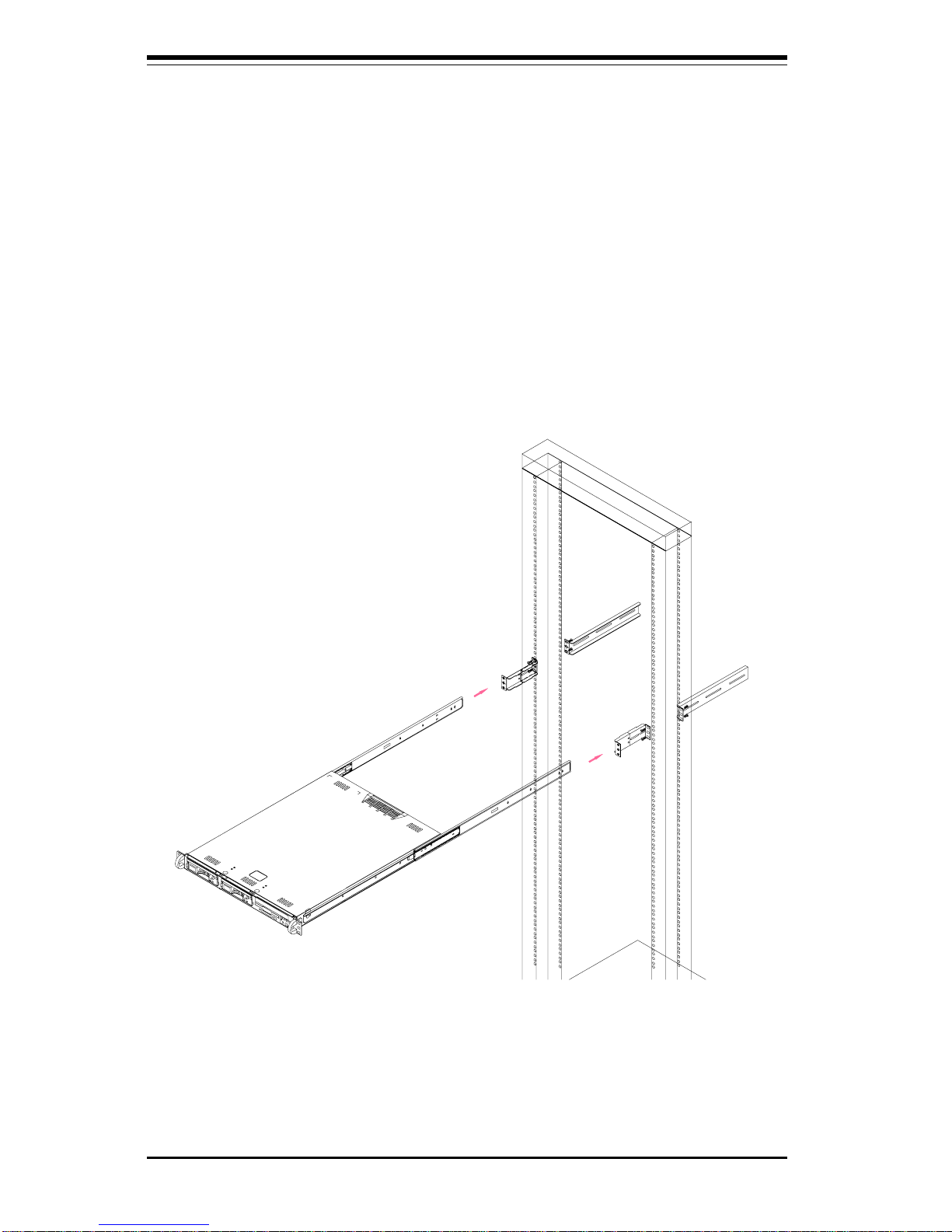
Figure 2-4. Installing the Server into a Telco Rack
Installing the Server into a Telco Rack
If you are installing the SuperServer 5011H/5011E into a Telco type rack,
follow the directions given on the previous pages for rack installation. The
only difference in the installation procedure will be the positioning of the
rack brackets to the rack. They should be spaced apart just enough to
accomodate the width of the telco rack.

Chapter 2: Server Installation
2-7
2-5 Checking the Motherboard Setup
After you install the 5011H/5011E in the rack, you will need to open the unit
to make sure the motherboard is properly installed and all the connections
have been made.
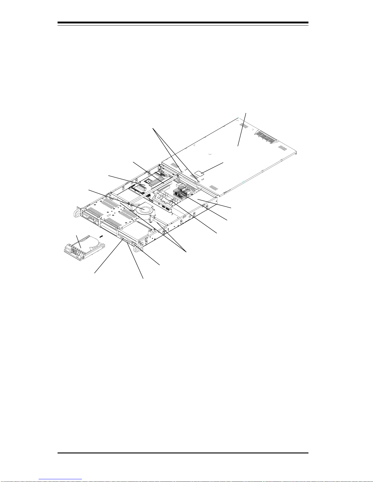
1. Accessing the inside of the 5011H/5011E (see Figure 2-5a/2-5b)
First, release the retention screws that secure the unit to the rack.
Grasp the two handles on either side and pull the unit straight out until it
locks (you will hear a "click"). Next, depress the two buttons on the top
of the chassis to release the top cover. There is a large rectangular
recess in the middle front of the top cover to help you push the cover
away from you until it stops. You can then lift the top cover from the
chassis to gain full access to the inside of the server.
2. Check the CPU (processor)
You should have one processor already installed into the system
board. Each processor should have its own heatsink attached. See
Section 5-5 for instructions on processor installation.
3. Verify the proper CPU core/bus ratio setting
The CPU FSB speed is set with jumpers JP11 and JP12 (see Section 5-9
for details). The CPU speed can also be changed by software control in
BIOS (see CPU Speed Setting). The CPU Speed Setting will show you
the actual CPU speed for each FSB speed option selected.
4. Check the system memory
Your 5011H/5011E server system may have come with system memory
already installed. Make sure all DIMMs are fully seated in their slots. For
details on adding system memory, refer to Section 5-5.
5. Installing add-on cards
If desired, you can install an add-on card to the system. See Section 57 for details on installing a PCI add-on card.
6. Check all cable connections and airflow
Make sure all power and data cables are properly connected and not
blocking the airflow. See Section 5-3 for details on cable connections.
Also, check the air seals for damage. The air seals are located under
the blower fan and beneath the frame cross section that separates the
drive bay area from the motherboard area of the chassis.
Note: Make sure that the air seals are properly installed.
2-8
SUPERSERVER 5011H/5011E Manual
Power Supply
Cover Recess
Cover Release
Buttons
Top Chassis Cover (Removed)
PCI Riser Card
Retention Rail
Air Seals
Blower Fan
SCSI Drive
CD-ROM Drive
Floppy Drive
Control Panel
System
Memory
P3TSSR Motherboard
Figure 2-5a.
Accessing the Inside of the SuperServer 5011H
(with SCSI installed)
5011H
CPU Heatsink
Chapter 2: Server Installation
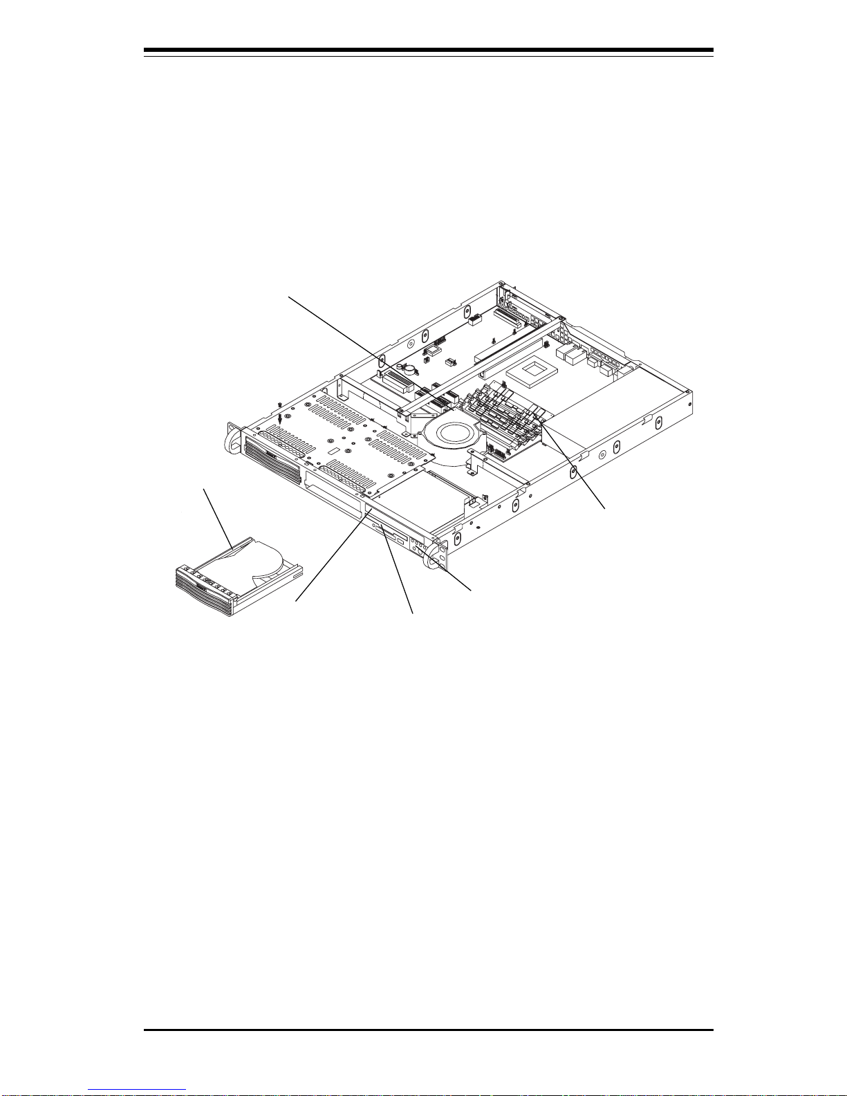
2-9
System
Memory
Blower Fan
Floppy Drive
CD-ROM Drive
Control Panel
IDE Drive
5011E
Figure 2-5b.
Accessing the Inside of the SuperServer 5011E
(with IDE installed)

2-10
SUPERSERVER 5011H/5011E Manual
2-6 Checking the Drive Bay Setup
Next, you should check to make sure the peripheral drives and the SCSI
drives (5011H only) and SCA backplane have been properly installed and
all connections have been made.
1. Accessing the drive bays
All drives can be accessed from the front of the server. For servicing
the CD-ROM and floppy drives, you will need to remove the top chassis
cover. The SCSI disk drives can be installed and removed from the front
of the chassis without removing the top chassis cover.
2. Installing a CD-ROM and floppy disk drives
Refer to Section 6-4 if you need to reinstall a CD-ROM and/or floppy disk
drive to the system.
3. Check the SCSI disk drives (5011H)
Depending upon your system's configuration, your system may have one
or two SCSI drives already installed. If you need to install SCSI drives,
please refer to Section 6-4.
4. Check the airflow
Airflow is provided by a 10-cm input fan and one (optional) 4-cm cooling
fan. The system component layout was carefully designed to promote
sufficient airflow through the small 1U rackmount space. Also note that
all power and data cables have been routed in such a way that they do
not block the airflow generated by the fans.
5. Supplying power to the system
The last thing you must do is to provide input power to the system. Plug
the power cord from the power supply unit into a high-quality power
strip that offers protection from electrical noise and power surges. It is
recommended that you use an uninterruptible power supply (UPS).
Chapter 3: System Interface
3-1
Chapter 3
System Interface
3-1 Overview
There are several LEDs on the control panel as well as others on the SCSI
drive carriers and the motherboard to keep you constantly informed of the
overall status of the system as well as the activity and health of specific
components. There are also two buttons on the chassis control panel and
an on/off switch on the power supply. This chapter explains the meanings
of all LED indicators and the appropriate response you may need to take.
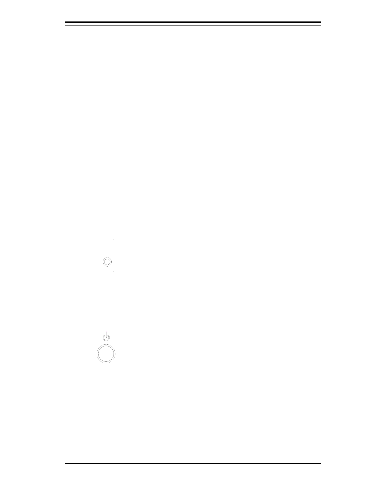
3-2 Control Panel Buttons
There are two push-button buttons located on the front of the chassis.
These are (in order from left to right) a reset button and a power on/off
button.
l RESET: The reset switch reboots the system.
l POWER: This is the main power switch, which is used to apply or
turn off the main system power. Turning off system power with this button
removes the main power but keeps standby power supplied to the system.
(See also the power supply on/off switch in Section 3-5.)
RESET
SUPERSERVER 5011H/5011E Manual
3-2
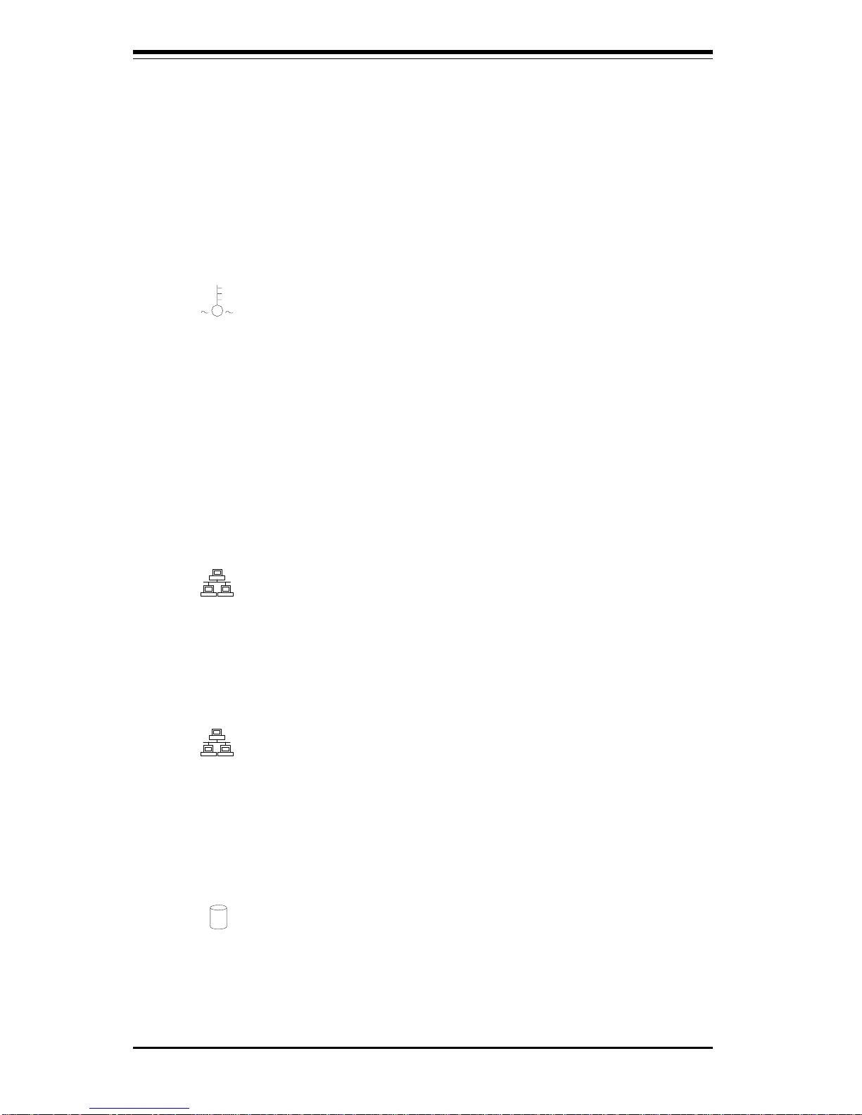
3-3 Control Panel LEDs
The control panel located on the front of the SC810 chassis has five LEDs.
These LEDs provide you with critical information related to different parts of
the system. This section explains what each LED indicates when illuminated and any corrective action you may need to take.
l OVERHEAT: Indicates an overheat condition in the chassis. This may
be caused by cables obstructing the airflow in the system, or the ambient
room temperature being too warm. You should also check to make sure
that the chassis cover is installed and that all fans are present and operating normally. Finally, check the air seals for damage. The air seals are
located under the blower fan and beneath the frame cross section that
separates the drive bay area from the motherboard area of the chassis.
l NIC2: Indicates network activity on LAN2 when flashing.
l NIC1: Indicates network activity on LAN1 when flashing.
l HDD: Indicates IDE channel activity. On the SuperServer 5011H/
5011E, this light indicates CD-ROM drive activity when flashing.
NIC2
NIC1
 Loading...