

Supero SuperServer 4048B-TRFT User Manual
®
SUPER
USER'S MANUAL
Revision 1.0a
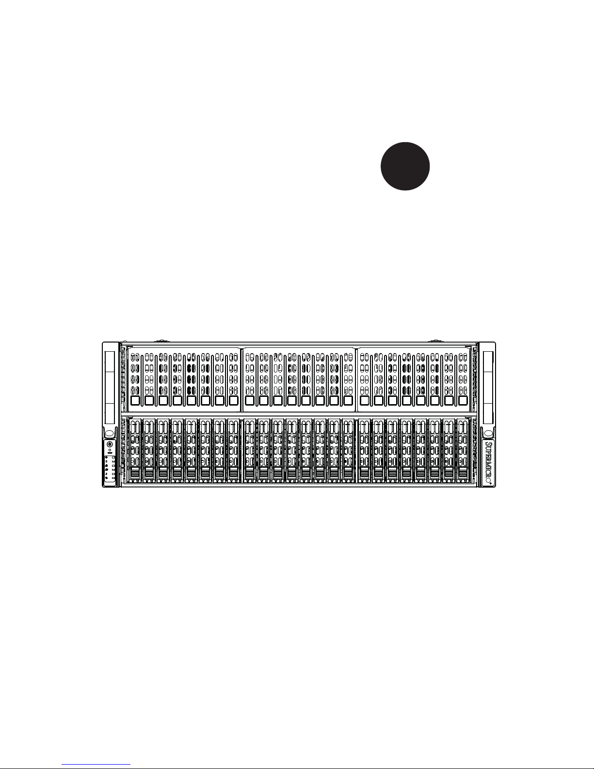
SuperServer
4048B-TRFT

The information in this User’s Manual has been carefully reviewed and is believed to be accurate.
The vendor assumes no responsibility for any inaccuracies that may be contained in this document,
makes no commitment to update or to keep current the information in this manual, or to notify any
person or organization of the updates. Please Note: For the most up-to-date version of this
manual, please see our web site at
www.supermicro.com.
Super Micro Computer, Inc. ("Supermicro") reserves the right to make changes to the product
described in this manual at any time and without notice. This product, including software and
documentation, is the property of Supermicro and/or its licensors, and is supplied only under a
license. Any use or reproduction of this product is not allowed, except as expressly permitted by
the terms of said license.
IN NO EVENT WILL SUPERMICRO BE LIABLE FOR DIRECT, INDIRECT, SPECIAL, INCIDENTAL,
SPECULATIVE OR CONSEQUENTIAL DAMAGES ARISING FROM THE USE OR INABILITY TO
USE THIS PRODUCT OR DOCUMENTATION, EVEN IF ADVISED OF THE POSSIBILITY OF
SUCH DAMAGES. IN PARTICULAR, SUPERMICRO SHALL NOT HAVE LIABILITY FOR ANY
HARDWARE, SOFTWARE, OR DATA STORED OR USED WITH THE PRODUCT, INCLUDING THE
COSTS OF REPAIRING, REPLACING, INTEGRATING, INSTALLING OR RECOVERING SUCH
HARDWARE, SOFTWARE, OR DATA.
Any disputes arising between manufacturer and customer shall be governed by the laws of Santa
Clara County in the State of California, USA. The State of California, County of Santa Clara shall
be the exclusive venue for the resolution of any such disputes. Super Micro's total liability for all
claims will not exceed the price paid for the hardware product.
FCC Statement: This equipment has been tested and found to comply with the limits for a Class
A digital device pursuant to Part 15 of the FCC Rules. These limits are designed to provide
reasonable protection against harmful interference when the equipment is operated in a commercial
environment. This equipment generates, uses, and can radiate radio frequency energy and, if not
installed and used in accordance with the manufacturer’s instruction manual, may cause harmful
interference with radio communications. Operation of this equipment in a residential area is likely
to cause harmful interference, in which case you will be required to correct the interference at your
own expense.
California Best Management Practices Regulations for Perchlorate Materials: This Perchlorate
warning applies only to products containing CR (Manganese Dioxide) Lithium coin cells. “Perchlorate
Material-special handling may apply. See
s”
WARNING: Handling of lead solder materials used in this
product may expose you to lead, a chemical known to
the State of California to cause birth defects and other
reproductive harm.
Manual Revision 1.0a
Release Date: June 24, 2014
Unless you request and receive written permission from Super Micro Computer, Inc., you may not
copy any part of this document.
Information in this document is subject to change without notice. Other products and companies
referred to herein are trademarks or registered trademarks of their respective companies or mark
holders.
Copyright © 2014 by Super Micro Computer, Inc.
All rights reserved.
Printed in the United States of America

iii
Preface
Preface
About This Manual
This manual is written for professional system integrators and PC technicians. It
provides information for the installation and use of the SuperServer 4048B-TRFT.
Installation and maintainance should be performed by experienced technicians only.
The SuperServer 4048B-TRFT is a high-end server based on the SC418XTAR3240B 4U rackmount chassis and the quad processor X10QBI serverboard, the
X10QBI-MEM1 memory module card and the AOM-X10QBI-A I/O card.
Manual Organization
Chapter 1: Introduction
The fi rst chapter provides a checklist of the main components included with the
server system and describes the main features of the X10QBI serverboard and the
SC418XTA-R3240B chassis.
Chapter 2: Server Installation
This chapter describes the steps necessary to install the SuperServer 4048B-TRFT
into a rack and check out the server confi guration prior to powering up the system.
If your server was ordered without processor and memory components, this chapter
will refer you to the appropriate sections of the manual for their installation.
Chapter 3: System Interface
Refer here for details on the system interface, which includes the functions and
information provided by the control panel on the chassis as well as other LEDs
located throughout the system.
Chapter 4: Standardized Warning Statements
You should thoroughly familiarize yourself with this chapter for a general overview
of safety precautions that should be followed when installing and servicing the
4048B-TRFT.
Chapter 5: Advanced Serverboard Setup
Chapter 5 provides detailed information on the X10QBI serverboard, including the
locations and functions of connections, headers and jumpers. Refer to this chapter
when adding or removing processors or main memory and when reconfi guring the
serverboard.

SUPERSERVER 4048B-TRFT USER'S MANUAL
iv
Chapter 6: Advanced Chassis Setup
Refer to Chapter 6 for detailed information on the SC418XTA-R3240B server
chassis. You should follow the procedures given in this chapter when installing,
removing or reconfi guring SATA or peripheral drives and when replacing system
power supply units and cooling fans.
Chapter 7: BIOS
The BIOS chapter includes an introduction to BIOS and provides detailed information
on running the CMOS Setup Utility.
Appendix A: BIOS Error Beep Codes
Appendix B: System Specifi cations

v
SUPERSERVER 4048B-TRFT USER'S MANUAL
Notes

vi
Table of Contents
Chapter 1 Introduction
1-1 Overview ......................................................................................................... 1-1
1-2 Serverboard Features ..................................................................................... 1-2
Processors ...................................................................................................... 1-2
Memory ........................................................................................................... 1-2
Serial ATA ....................................................................................................... 1-2
PCI Expansion Slots ....................................................................................... 1-2
1-3 Server Chassis Features ................................................................................ 1-3
System Power ................................................................................................. 1-3
SATA Subsystem ............................................................................................. 1-3
Front Control Panel ......................................................................................... 1-3
I/O Ports .......................................................................................................... 1-3
Cooling System ............................................................................................... 1-3
Air Shrouds ..................................................................................................... 1-3
Mounting Rails ................................................................................................ 1-4
1-4 Memory Modules ............................................................................................. 1-4
1-5 I/O Card ........................................................................................................... 1-4
1-6 Contacting Supermicro .................................................................................... 1-6
Chapter 2 Rack Installation
2-1 Overview ......................................................................................................... 2-1
2-2 Unpacking the System .................................................................................... 2-1
2-3 Preparing for Setup ......................................................................................... 2-1
Choosing a Setup Location ............................................................................. 2-1
2-4 Warnings and Precautions .............................................................................. 2-2
Rack Precautions ............................................................................................ 2-2
General Server Precautions ............................................................................ 2-2
Rack Mounting Considerations ....................................................................... 2-3
Ambient Operating Temperature ................................................................ 2-3
Reduced Airfl ow ......................................................................................... 2-3
Mechanical Loading ................................................................................... 2-3
Circuit Overloading ..................................................................................... 2-3
Reliable Ground ......................................................................................... 2-3
2-5 Rack Mounting Instructions ............................................................................. 2-4
Identifying the Sections of the Rack Rails ...................................................... 2-4
Installing the Inner Rails on the Chassis ........................................................ 2-4
Releasing the Inner Rail ................................................................................. 2-5
Installing The Inner Rails on the Chassis ....................................................... 2-6
SUPERSERVER 4048B-TRFT USER'S MANUAL

vii
Installing the Outer Rails on the Rack ............................................................ 2-7
Standard Chassis Installation ......................................................................... 2-8
Optional Quick Installation Method ................................................................. 2-9
Chapter 3 System Interface
3-1 Overview ......................................................................................................... 3-1
3-2 Control Panel Buttons ..................................................................................... 3-2
3-3 Drive Carrier LEDs .......................................................................................... 3-4
3-4 Power Supply LEDs ........................................................................................ 3-4
Chapter 4 Standardized Warning Statements for AC Systems
4-1 About Standardized Warning Statements ....................................................... 4-1
Warning Defi nition ........................................................................................... 4-1
Installation Instructions .................................................................................... 4-4
Circuit Breaker ................................................................................................ 4-5
Power Disconnection Warning ........................................................................ 4-6
Equipment Installation ..................................................................................... 4-8
Restricted Area ................................................................................................ 4-9
Battery Handling ............................................................................................ 4-10
Redundant Power Supplies .......................................................................... 4-12
Backplane Voltage ........................................................................................ 4-13
Comply with Local and National Electrical Codes ........................................ 4-14
Product Disposal ........................................................................................... 4-15
Hot Swap Fan Warning ................................................................................. 4-16
Power Cable and AC Adapter ...................................................................... 4-18
Chapter 5 Advanced Serverboard Setup
5-1 Handling the Serverboard ............................................................................... 5-1
Precautions ..................................................................................................... 5-1
Unpacking ....................................................................................................... 5-1
5-2 Connecting Cables .......................................................................................... 5-2
Connecting Data Cables ................................................................................. 5-2
5-3 Control Panel Connectors and I/O Ports ........................................................ 5-3
Connecting the Control Panel ......................................................................... 5-4
5-4 Processor and Heatsink Installation................................................................ 5-5
Installing the E7-4800 V2 Processors............................................................. 5-5
Installing a Passive CPU Heatsink ................................................................. 5-9
Removing the Heatsink ................................................................................... 5-9
5-5 Installing Memory .......................................................................................... 5-10
Installing Memory .......................................................................................... 5-10
Memory Support ............................................................................................ 5-10
Populating RDIMM/LRDIMM (ECC) Memory Modules ............................ 5-12
Table of Contents

viii
5-6 I/O Module Board .......................................................................................... 5-13
5-7 Adding PCI Expansion Cards ....................................................................... 5-14
5-8 Baseboard Details ......................................................................................... 5-15
X10QBi-F Quick Reference........................................................................... 5-16
5-9 Connector Defi nitions .................................................................................... 5-17
5-10 Jumper Settings ............................................................................................ 5-24
Explanation of Jumpers ................................................................................ 5-24
5-11 Onboard Indicators ........................................................................................ 5-27
5-12 Serial ATA Ports ............................................................................................ 5-28
5-13 Installing Software ......................................................................................... 5-29
SuperDoctor® 5 ............................................................................................ 5-30
5-14 Onboard Battery ............................................................................................ 5-31
Chapter 6 Advanced Chassis Setup
6-1 Static-Sensitive Devices .................................................................................. 6-1
Precautions ..................................................................................................... 6-1
Unpacking ....................................................................................................... 6-1
6-2 Control Panel .................................................................................................. 6-2
6-3 Installing Hard Drives ...................................................................................... 6-3
6-4 Accessing the Inside of the System................................................................ 6-5
Removing the Chassis Cover ......................................................................... 6-5
6-5 Installing the Air Shroud .................................................................................. 6-6
Air Shrouds ..................................................................................................... 6-6
6-6 Cooling System ............................................................................................... 6-7
6-7 Power Supply ................................................................................................. 6-9
Power Supply Replacement ............................................................................ 6-9
Chapter 7 BIOS
7-1 Introduction ...................................................................................................... 7-1
Starting BIOS Setup Utility .............................................................................. 7-1
How To Change the Confi guration Data ......................................................... 7-2
Starting the Setup Utility ................................................................................. 7-2
7-2 Main Setup ...................................................................................................... 7-2
7-3 Advanced Setup Confi gurations...................................................................... 7-4
7-4 IPMI ............................................................................................................... 7-43
7-5 Security ......................................................................................................... 7-44
7-6 Boot ............................................................................................................... 7-48
7-7 Save & Exit ................................................................................................... 7-50
Appendix A BIOS Error Beep Codes
Appendix B System Specifi cations
SUPERSERVER 4048B-TRFT USER'S MANUAL

Chapter 1
Introduction
1-1 Overview
The SuperServer 4048B-TRFT is a high-end server comprised of four main
subsystems: the SC418XTA-R3240B 4U server chassis and the X10QBI quad
processor serverboard (baseboard), eight X10QBI-MEM1 memory module cards
and one AOM-X10QBI-A I/O card. Please refer to our web site for information on
operating systems that have been certifi ed for use with the system (www.supermicro.
com).
In addition to the serverboard and chassis, various hardware components have been
included with the SuperServer 4048B-TRFT server, as listed below:
• Four passive heatsinks (SNK-P0048PS)
• One air shroud (MCP-310-41804-0B)
• Four 9-cm cooling fans (FAN-0146L4)
• Three 8-cm rear exhaust fans (FAN-0148L4)
• One SATA backplane (BPN-SAS3-216A)
• Twenty-four hot-swap 2.5" HDD trays (MCP-220-00047-0B)
• One rail set (MCP-290-00057-0N)
Note: For your system to work properly, please follow the links below to download
all necessary drivers/utilities and the user’s manual for your server.
• Supermicro product manuals: http://www.supermicro.com/support/manuals/
• Product drivers and utilities: ftp://ftp.supermicro.com
• Product safety info: http://super-dev/about/policies/safety_information.cfm
• If you have any questions, please contact our support team at:
support@supermicro.co
Chapter 1: Introduction
1-1

1-2
SUPERSERVER 4048B-TRFT USER'S MANUAL
1-2 Serverboard Features
At the heart of the SuperServer 4048B-TRFT lies the X10QBI, a quad processor
serverboard based on the Intel® C602J chipset and designed to provide maximum
performance. The X10QBI acts as a baseboard, into which an I/O card and memory
cards may be installed.
The sections below cover the main features of the X10QBI serverboard (see Figure
1-1 for a block diagram of the chipset).
Processors
The X10QBI supports four Intel® Xeon® E7-4800 V2 series processors (Socket R1
LGA 2011). Please refer to the serverboard description pages on our web site for a
complete listing of supported processors (www.supermicro.com).
Memory
The X10QBI uses eight memory cards that install into the eight memory slots on
the serverboard. Two cards are assigned to each CPU as follows: SMI slots P1M1/
P1M2 for CPU1, SMI slots P2M1/P2M2 for CPU2, SMI slots P3M1/P3M2 for CPU3
and SMI slots P4M1/P4M2 for CPU4.
Each memory card may be populated with up to 12 DIMMs. With all cards fully
populated, the system will support up to a total of 6 TB of DDR3-1600/1333/1066/800
ECC RDIMM/LDIMM memory. See Chapter 5 for details.
Note: Check the Supermicro website (www.supermicro.com) for the latest memory
support information.
Serial ATA
A SATA controller is integrated into the C602J chipset to provide two SATA 3.0
and four SATA 2.0 ports, which support RAID 0, 1, 5 and 10. The SATA drives are
hot-swappable units.
PCI Expansion Slots
The X10QBI serverboard has four PCI Express 3.0 x16 slots and seven PCI Express
3.0 x8 slots.

1-3
Chapter 1: Introduction
1-3 Server Chassis Features
The following is a general outline of the main features of the SC418XTA server
chassis.
System Power
The SC418XTA chassis model includes four 1620W power supplies consisting of
two active and two backup power modules. In the unlikely event your power supply
fails, replacement is simple and can be accomplished without tools.
SATA Subsystem
The SC418XTA supports up to 24 2.5" hot-swap hard drives. These drives are
connected to a backplane that provides power and control. As an option, an extra
backplane may be installed to support a total of up to 48 2.5" drives.
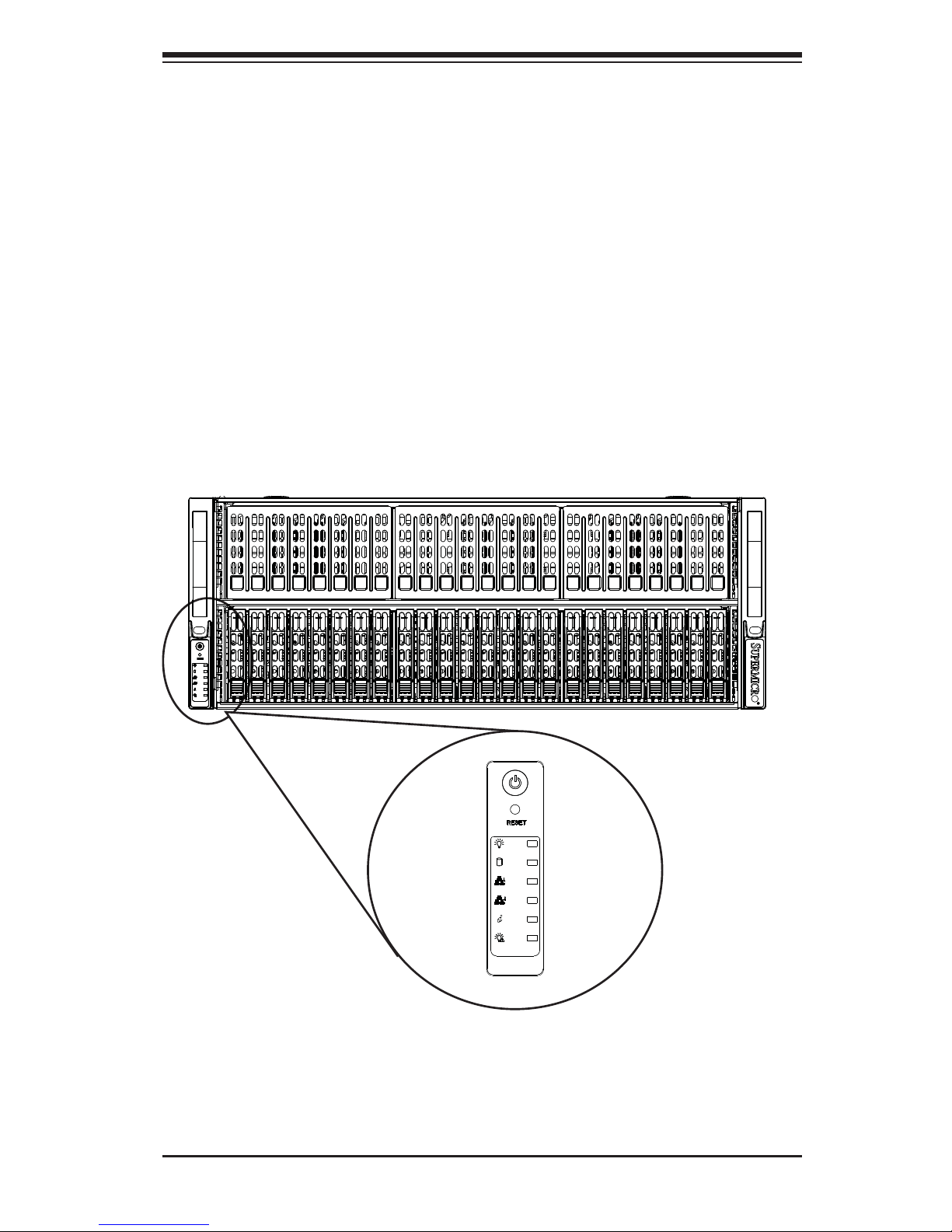
Front Control Panel
The SC418XTA chassis includes a control panel below the left handle of the chassis.
The control panel provides you with system monitoring and control. LEDs indicate
system power, HDD activity, network activity, an information LED and power supply
failure. A main power button and a system reset button are also included.
I/O Ports
The chassis provides eight full-height, full-length expansion card slots, a COM port,
two USB 2.0 ports and, on the I/O card, a VGA port, two 10 Gb Ethernet ports and
a dedicated IPMI Ethernet port.
Cooling System
Four 9-cm and three 8-cm system fans are powered from the chassis and controlled
via IPMI.
Air Shrouds
The SC418XTA chassis includes one mylar air shroud, which directs the airfl ow
where cooling is needed. Always use the air shroud included with your server.
Note: if four memory modules are installed, an additional air shroud must be used
(p/n MCP-310-41805-0B). See Chapter 6 for details.

1-4
SUPERSERVER 4048B-TRFT USER'S MANUAL
Mounting Rails
The SC418XTA includes a set of quick-release rails, and can be placed in a rack
for secure storage and use. To setup your rack, follow the instructions included in
Chapter 2.
1-4 Memory Modules
The X10QBI-MEM1 memory boards plug directly into the X10QBI baseboard. The
memory boards feature a Jordan Creek C104 memory buffer chip. Each of these
buffer chips supports two channels (three DIMMs per channel). See Chapter 5 for
installation and details.
1-5 I/O Card
The AOM-X10QBI-A I/O card also is inserted directly into the X10QBI baseboard.
The I/O card includes an Intel X540 Ethernet controller and an ASP2400 BMC chip
to provide dual 10G based-T (RJ45) Ethernet ports and a dedicated IPMI port. This
chip also provides onboard video. See Chapter 5 for installation and details.
1-5
Chapter 1: Introduction
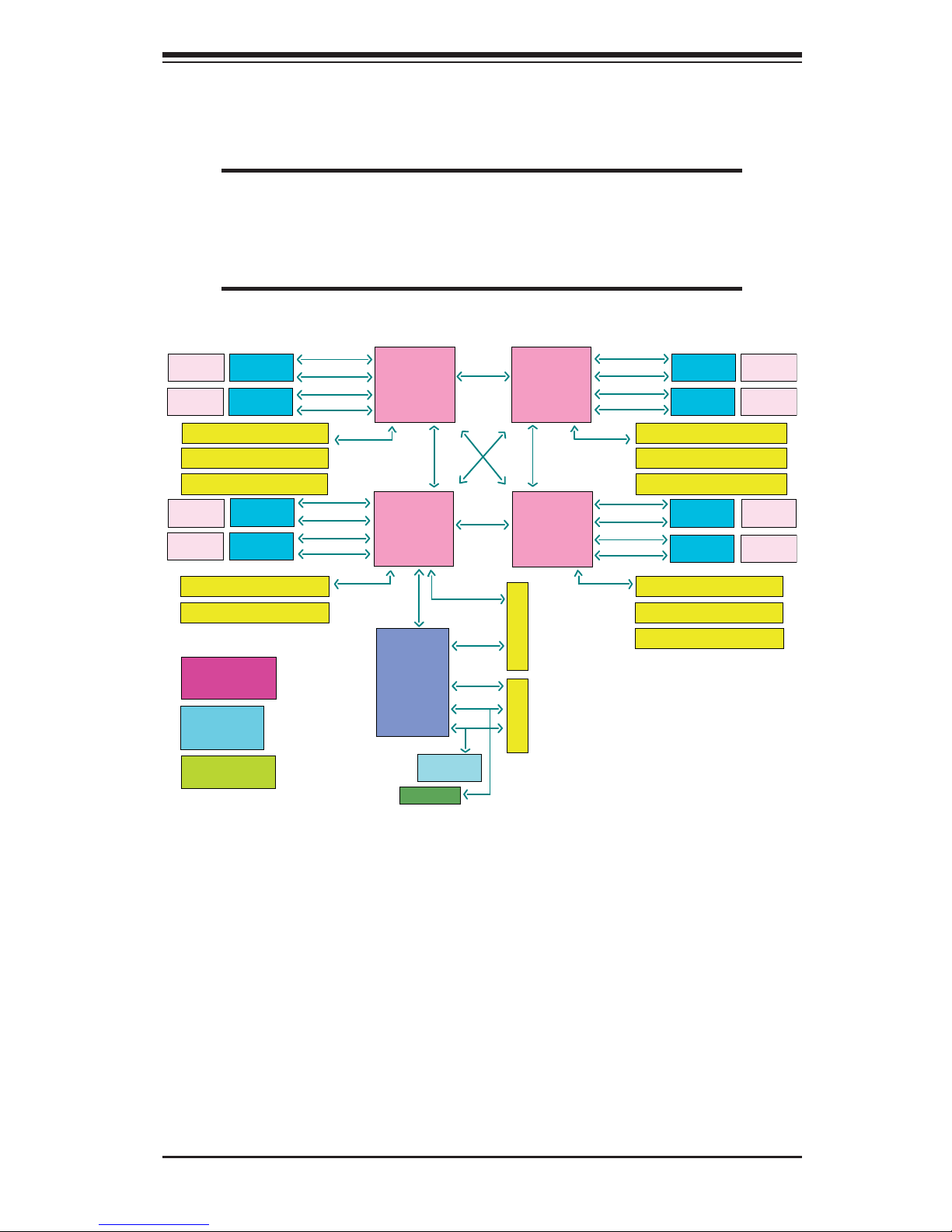
Figure 1-1. Intel C602J Chipset:
System Block Diagram
Note: This is a general block diagram and may not exactly repre-
sent the features on your serverboard. See the previous pages for
the actual specifi cations of your serverboard. This block diagram is
intended for your reference only.
CPU3
IVB EX
HSW EX
BDW EX
CPU4
IVB EX
HSW EX
BDW EX
CPU2
IVB EX
HSW EX
BDW EX
CPU1
IVB EX
HSW EX
BDW EX
Intel
C602J
Patsburg
IO Slot/ x16 slot
IO Slot/ x8 slot
TPM Chip
HM
NCT7904D
CPU3_S1-PCIE G3x8 in X8slot
CPU3_S2-PCIE G3x8 in X8slot
CPU3_S3-PCIE G3x16 in X16slot
CPU2_S1-PCIE G3x8 in X8slot
CPU2_S2-PCIE G3x16 in X16slot
CPU2_S3-PCIE G3x8 in X8slot
CPU3_S2-PCIE G3x8 in X8slot
CPU3_S3-PCIE G3x16 in X16slot
CPU4_S1-PCIE G3x8 in X8slot
CPU4_S2-PCIE G3x8 in X8slot
CPU4_S3-PCIE G3x16 in X16slot
LPC
SMBus
USB
PCIE x1
X4 DMI2
PCIE-G3x32 LANEs
PCIE-G3x32 LANEs
PCIE-G3x32 LANEs
PCIE-G3x24
LANEs
PCIE-G3x8 LANEs
QPI 8 GT/s
QPI 8 GT/s
QPI 8 GT/s
QPI 8 GT/s
QPI 8 GT/s
SMI2 Slot
SMI2 Slot
SMI2 Slot
SMI2 Slot
SMI2 Slot
SMI2 Slot
SMI2 Slot
SMI2 Slot
Power
Connector
Power
Connector
Power
Connector
Power
Connector
Power
Connector
Power
Connector
Power
Connector
Power
Connector
SMI2-CH0-2.66GT/s
SMI2-CH1-2.66GT/s
SMI2-CH2-2.66GT/s
SMI2-CH3-2.66GT/s
SMI2-CH0-2.66GT/s
SMI2-CH1-2.66GT/s
SMI2-CH2-2.66GT/s
SMI2-CH3-2.66GT/s
SMI2-CH0-2.66GT/s
SMI2-CH1-2.66GT/s
SMI2-CH2-2.66GT/s
SMI2-CH3-2.66GT/s
SMI2-CH0-2.66GT/s
SMI2-CH1-2.66GT/s
SMI2-CH2-2.66GT/s
SMI2-CH3-2.66GT/s
XDP0: CPU1 & CPU4
CPU2 & CPU3
Clock Subsystem
Clock Gen
Clock Buffer
CPLD
Power Management
Reset & PowerGood

1-6
SUPERSERVER 4048B-TRFT USER'S MANUAL
1-6 Contacting Supermicro
Headquarters
Address: Super Micro Computer, Inc.
980 Rock Ave.
San Jose, CA 95131 U.S.A.
Tel: +1 (408) 503-8000
Fax: +1 (408) 503-8008
Email: marketing@supermicro.com (General Information)
support@supermicro.com (Technical Support)
Web Site:
www.supermicro.com
Europe
Address: Super Micro Computer B.V.
Het Sterrenbeeld 28, 5215 ML
's-Hertogenbosch, The Netherlands
Tel: +31 (0) 73-6400390
Fax: +31 (0) 73-6416525
Email: sales@supermicro.nl (General Information)
support@supermicro.nl (Technical Support)
rma@supermicro.nl (Customer Support)
Web Site:
www.supermicro.nl
Asia-Pacifi c
Address: Super Micro Computer, Inc.
3F, No. 150, Jian 1st Rd.
Zhonghe Dist., New Taipei City 235
Taiwan (R.O.C)
Tel: +886-(2) 8226-3990
Fax: +886-(2) 8226-3992
Email: support@supermicro.com.tw
Web Site:
www.supermicro.com.tw

2-1
Chapter 2: Server Installation
Chapter 2
Rack Installation
2-1 Overview
This chapter provides a quick setup checklist to get your chassis up and running.
Following these steps in the order given should enable you to have the system
operational within a minimal amount of time.
2-2 Unpacking the System
You should inspect the box which the chassis was shipped in and note if it was
damaged in any way. If the chassis itself shows damage, you should fi le a damage
claim with the carrier who delivered it.
Decide on a suitable location for the rack unit that will hold your chassis. It should
be situated in a clean, dust-free area that is well ventilated. Avoid areas where
heat, electrical noise and electromagnetic fi elds are generated. The system needs
to be placed near a grounded power outlet. Be sure to read the Rack and Server
Precautions in the next section.
2-3 Preparing for Setup
The box your chassis was shipped in should include two sets of rail assemblies and
the mounting screws needed for installing the system into the rack. Also included
is an optional square hole to round hole converter bracket, for use in racks with
round mounting holes. Please read this section in its entirety before you begin the
installation procedure outlined in the sections that follow.
Choosing a Setup Location
• Leave enough clearance in front of the rack to enable you to open the front
door completely (~25 inches).
• Leave approximately 30 inches of clearance in the back of the rack to allow for
suffi cient airfl ow and ease in servicing.
• This product is for installation only in a Restricted Access Location (dedicated
equipment rooms, service closets and the like).

2-2
SUPERSERVER 4048B-TRFT USER'S MANUAL
2-4 Warnings and Precautions
Rack Precautions
• Ensure that the leveling jacks on the bottom of the rack are fully extended to
the fl oor with the full weight of the rack resting on them.
• In single rack installations, stabilizers should be attached to the rack.
• In multiple rack installations, the racks should be coupled together.
• Always make sure that the rack is stable before extending a component from
the rack.
• You should extend only one component at a time - extending two or more si-
multaneously may cause the rack to become unstable.
General Server Precautions
• Review the electrical and general safety precautions that came with the com-
ponents you are adding to your chassis.
• Determine the placement of each component in the rack before you install the
rails.
• Install the heaviest server components on the bottom of the rack fi rst, and then
work upwards.
• Use a regulating uninterruptible power supply (UPS) to protect the server from
power surges, voltage spikes and to keep your system operating in case of a
power failure.
• Allow the hot plug hard drives and power supply modules to cool before touch-
ing them.
• Always keep the rack's front door and all panels and components on the servers
closed when not servicing to maintain proper cooling.
2-3
Chapter 2: Server Installation
Rack Mounting Considerations
Ambient Operating Temperature
If installed in a closed or multi-unit rack assembly, the ambient operating temperature of the rack environment may be greater than the ambient temperature of the
room. Therefore, consideration should be given to installing the equipment in an
environment compatible with the manufacturer’s maximum rated ambient temperature (TMRA).
Reduced Airfl ow
Equipment should be mounted into a rack so that the amount of airfl ow required
for safe operation is not compromised.
Mechanical Loading
Equipment should be mounted into a rack so that a hazardous condition does not
arise due to uneven mechanical loading.
Circuit Overloading
Consideration should be given to the connection of the equipment to the power
supply circuitry and the effect that any possible overloading of circuits might have
on overcurrent protection and power supply wiring. Appropriate consideration of
equipment nameplate ratings should be used when addressing this concern.
Reliable Ground
A reliable ground must be maintained at all times. To ensure this, the rack itself
should be grounded. Particular attention should be given to power supply connections other than the direct connections to the branch circuit (i.e. the use of power
strips, etc.).
Warning! To prevent bodily injury when mounting or servicing this unit in a
rack, you must take special precautions to ensure that the system remains
stable. The following guidelines are provided to ensure your safety:
• This unit should be mounted at the bottom of the rack if it is the only unit in
the rack.
• When mounting this unit in a partially fi lled rack, load the rack from the bottom
to the top with the heaviest component at the bottom of the rack.
• If the rack is provided with stabilizing devices, install the stabilizers before
mounting or servicing the unit in the rack.
2-4
SUPERSERVER 4048B-TRFT USER'S MANUAL
2-5 Rack Mounting Instructions
This section provides information on installing the chassis into a rack unit with the
rails provided. There are a variety of rack units on the market, which may mean
that the assembly procedure will differ slightly from the instructions provided. You
should also refer to the installation instructions that came with the rack unit you are
using. Note: This rail will fi t a rack between 26.5" and 36.4" deep
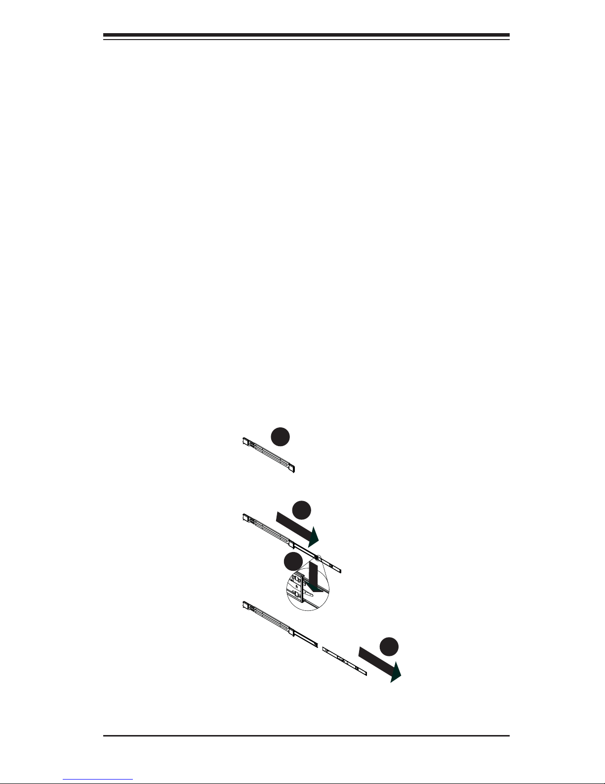
Identifying the Sections of the Rack Rails
The chassis package includes a rack rail assembly in the rack mounting kit. Each
assembly consists of three sections: An inner chassis rail which secures directly to
the chassis, an outer rail that secures to the rack, and a middle rail which extends
from the outer rail. These assemblies are specifi cally designed for the left and right
side of the chassis..
Installing the Inner Rails on the Chassis
Installing the Inner Rails
1. Place the inner rails on the side of the chassis aligning the hooks of the chassis with the inner rail holes. Make sure that the rail faces "outward" so that it
will fi t with the rack's mounting bracket.
2. Slide the rail toward the front of the chassis.
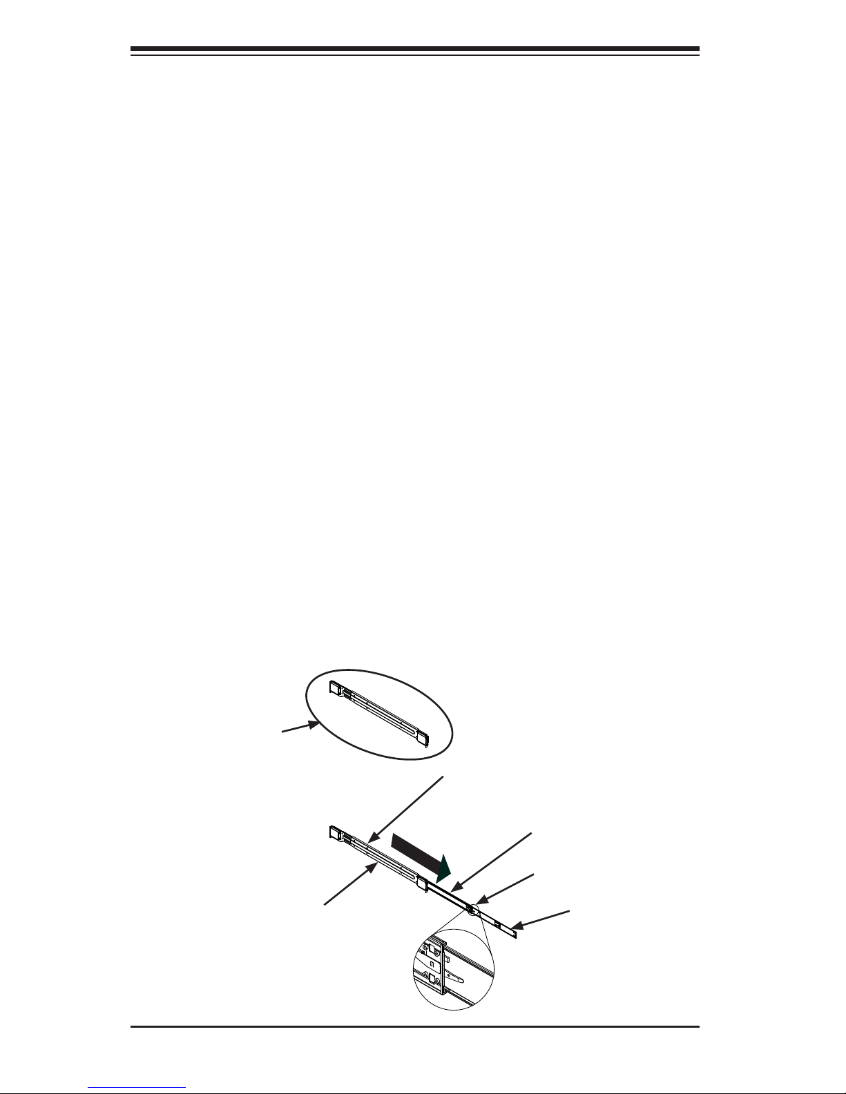
Figure 2-1. Identifying the Different Rail Sections
Inner Rail
Rail Assembly
(Shown with Rails
Retracted)
This Side Faces
Outward
Locking Tab
Middle Rail
Outer Rail
2-5
Chapter 2: Server Installation
Figure 2-2. Extending and Releasing the Inner Rail
3. Secure the rail to the chassis with four screws as illustrated.
4. Repeat steps 1-3 for the other inner rack rail.Locking Tabs
Each inner rail has a locking tab. This tab locks the chassis into place when installed
and pushed fully into the rack. These tabs also lock the chassis in place when fully
extended from the rack. This prevents the server from coming completely out of
the rack when when the chassis is pulled out for servicing.
Releasing the Inner Rail
Releasing Inner Rail from the Outer Rails
1. Identify the left and right outer rail assemblies as described on page 5-4.
2. Pull the inner rail out of the outer rail until it is fully extended as illustrated
below.
3. Press the locking tab down to release the inner rail.
4. Pull the inner rail all the way out.
5. Repeat steps 1-3 for the second outer rail.
1
2
1
1
1
3
1
4
2-6
SUPERSERVER 4048B-TRFT USER'S MANUAL
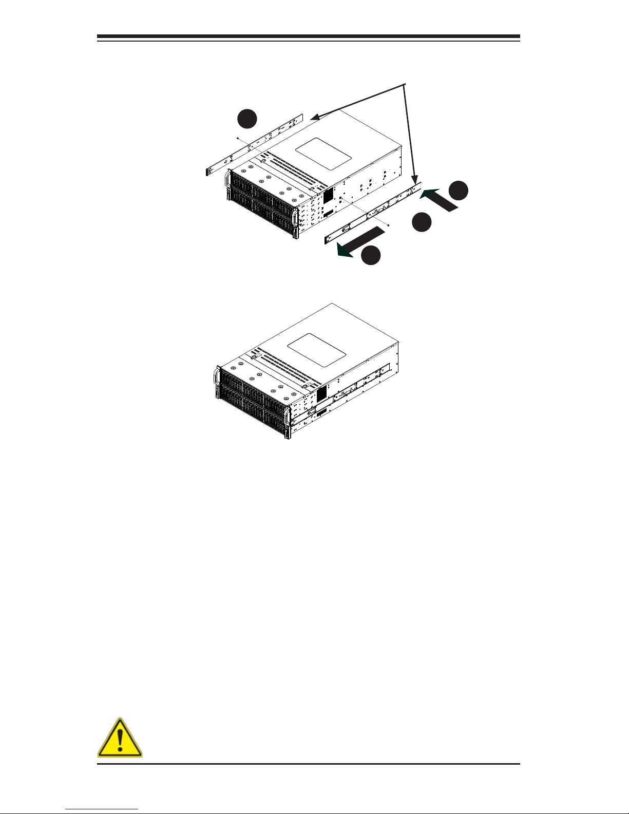
Figure 2-4. Inner Rails Installed on the Chassis
Figure 2-3. Installing the Inner Rails
Installing The Inner Rails on the Chassis
Installing the Inner Rails
1. Confi rm that the left and right inner rails have been correctly identifi ed.
2. Place the inner rail fi rmly against the side of the chassis, aligning the hooks
on the side of the chassis with the holes in the inner rail.
3. Slide the inner rail forward toward the front of the chassis until the rail clicks
into the locked position, which secures the inner rail to the chassis.
4. Secure the inner rail to the chassis with the screws provided.
5. Repeat steps 1 through 4 above for the other inner rail.
1
4
1
3
1
2
1
4
Inner Rails
Warning: do not pick up the server by the front handles. They are designed
to pull the system from a rack only.
2-7
Chapter 2: Server Installation
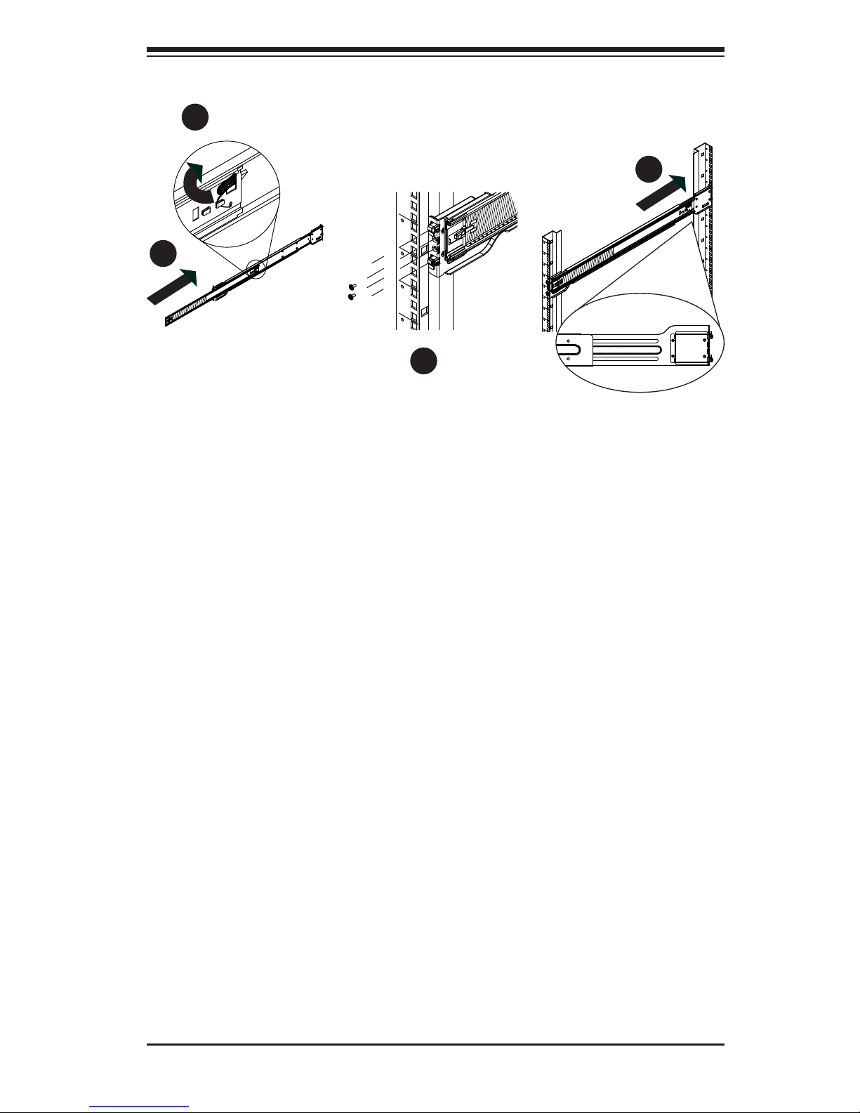
Installing the Outer Rails on the Rack
Installing the Outer Rails
1. Press upward on the locking tab at the rear end of the middle rail.
2. Push the middle rail back into the outer rail.
3. Hang the hooks of the front of the outer rail onto the slots on the front of
the rack. If necessary, use screws to secure the outer rails to the rack, as
illustrated above.
4. Pull out the rear of the outer rail, adjusting the length until it fi ts within the
posts of the rack.
5. Hang the hooks of the rear portion of the outer rail onto the slots on the rear
of the rack. If necessary, use screws to secure the rear of the outer rail to the
rear of the rack.
6. Repeat steps 1-5 for the remaining outer rail.
Figure 2-5. Extending and Releasing the Outer Rails
1
1
1
2
1
3
1
4
2-8
SUPERSERVER 4048B-TRFT USER'S MANUAL
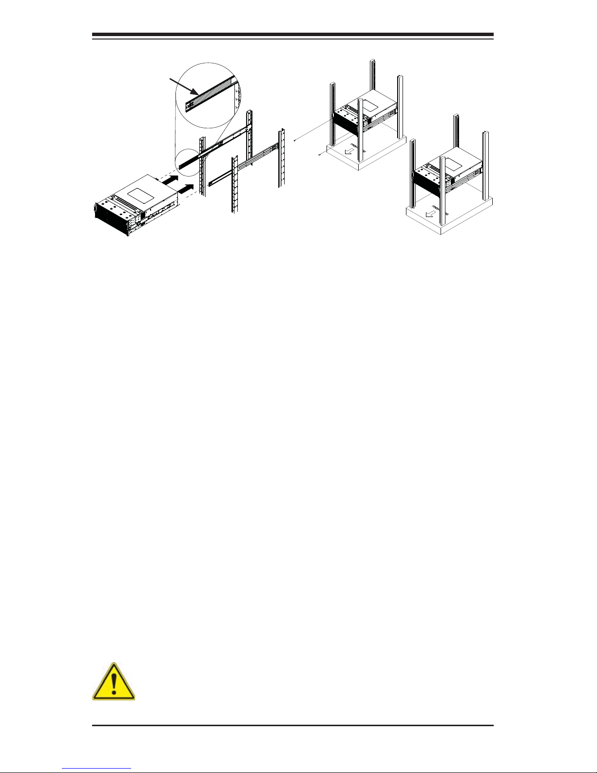
Figure 5-6: Installing into a Rack
Standard Chassis Installation
Installing the Chassis into a Rack
1. Confi rm that the inner rails are properly installed on the chassis.
2. Confi rm that the outer rails are correctly installed on the rack.
3. Pull the middle rail out from the front of the outer rail and make sure that the
ball-bearing shuttle is at the front locking position of the middle rail.
4. Align the chassis inner rails with the front of the middle rails.
5. Slide the inner rails on the chassis into the middle rails, keeping the pressure
even on both sides, until the locking tab of the inner rail clicks into the front of
the middle rail, locking the chassis into the fully extended position.
6. Depress the locking tabs of both sides at the same time and push the chassis
all the way into the rear of the rack.
7. If necessary for security purposes, use screws to secure the chassis handles
to the front of the rack.
Ball-Bearing
Shuttle
Stability hazard. The rack stabilizing mechanism must be in place, or the
rack must be bolted to the fl oor before you slide the unit out for servicing.
Failure to stabilize the rack can cause the rack to tip over.
Note: fi gures are for illustrative purposes only. Always install servers into racks
from the bottom up.

2-9
Chapter 2: Server Installation
Optional Quick Installation Method
The following quick installation method may be used to install the chassis onto a
rack.
Installing the Chassis into a Rack
1. Install the whole rail assembly onto the rack as described on page 2-7.
2. Release the inner rail without retracting the middle rail.
3. Install the inner rails on the chassis as previously described on page 2-6.
4. Install the chassis onto the middle rail as described in the previous section.

2-10
SUPERSERVER 4048B-TRFT USER'S MANUAL
Notes
Chapter 3: System Interface
3-1
Figure 3-1: Front LED Panel
Chapter 3
System Interface
3-1 Overview
There are several LEDs on the control panel as well as others on the drive carriers
to keep you constantly informed of the overall status of the system as well as the
activity and health of specifi c components.
This chapter explains the meanings of all LED indicators and the appropriate
responses you may need to take.

3-2
SUPERSERVER 4048B-TRFT USER'S MANUAL
3-2 Control Panel Buttons
There are two push-buttons included on the control panel: a power button and a
reset button.
Power
Indicates power is being supplied to the system's power supply units. This LED
should normally be illuminated when the system is operating.
Power
The main power button is used to apply or remove power from the power supply
to the server system. Turning off system power with this button removes the main
power but keeps standby power supplied to the system. Therefore, you must unplug
system before servicing.
Reset
The reset button is used to reboot the system.
HDD
Indicates SATA drive activity when fl ashing.
Chapter 3: System Interface
3-3
1
2
Information LED
See the table below for the various conditions indicated by the Information LED.
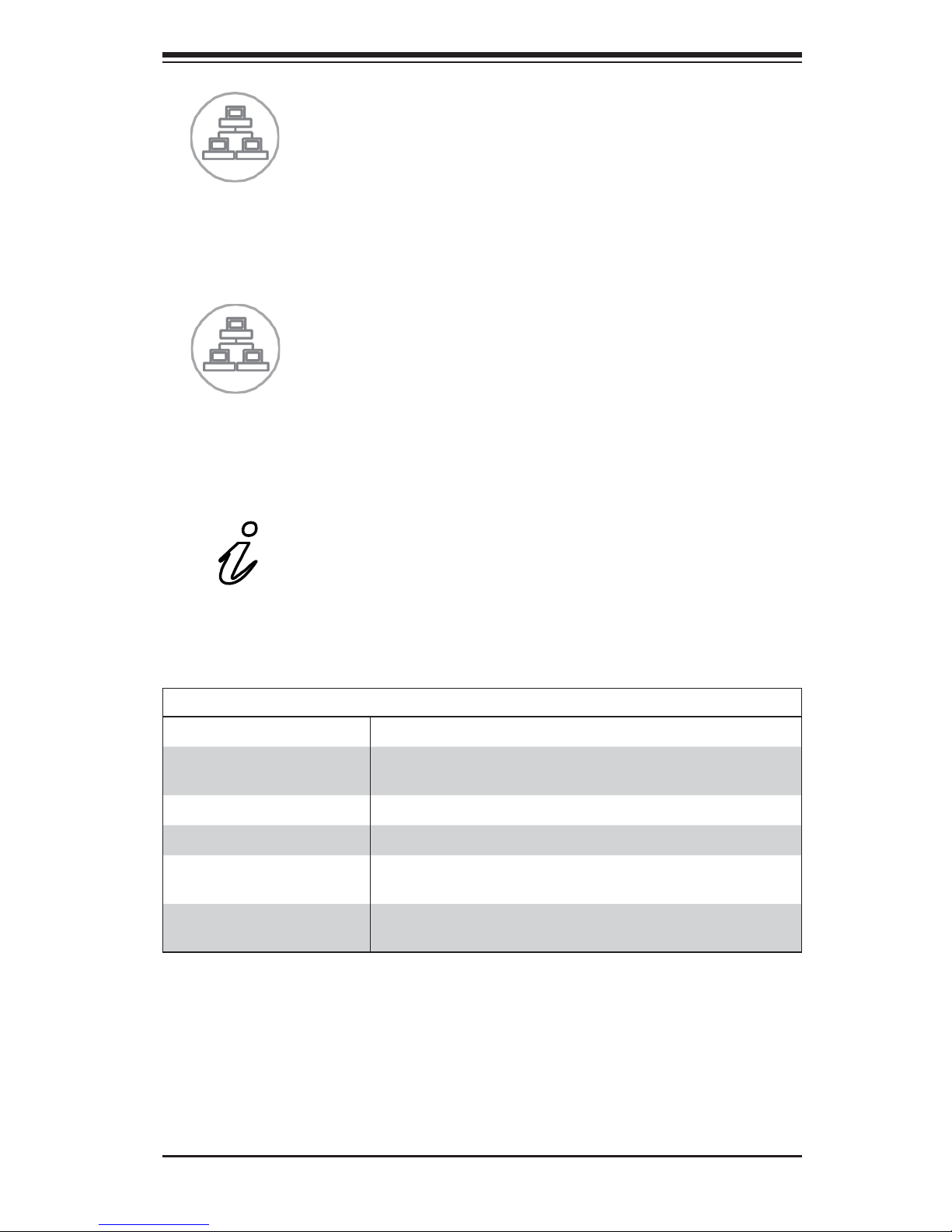
NIC1
Indicates network activity on GLAN1 when fl ashing.
NIC2
Indicates network activity on GLAN2 when fl ashing.
Information LED
Status Description
Continuously on and red
An overheat condition has occured.
(This may be caused by cable congestion.)
Blinking red (1Hz) Fan failure, check for an inoperative fan.
Blinking red (0.25Hz) Power failure, check for a non-operational power supply.
Solid blue
Local UID has been activated. Use this function to locate
the server in a rack mount environment.
Blinking blue
Remote UID is on. Use this function to identify the
server from a remote location.
If the server overheats:
• Use the LEDs to determine the nature of the overheating condition.
• Confi rm that the chassis covers are installed properly.
• Check the routing of the cables and make sure all fans are present and operating
normally.
• Verify that the heatsinks are installed properly.

3-4
SUPERSERVER 4048B-TRFT USER'S MANUAL
Power Failure
When this LED fl ashes, it indicates a failure in the redundant power supply.
3-3 Drive Carrier LEDs
The chassis includes externally accessable SATA drives. Each drive carrier displays
two status LEDs on the front of the carrier.
• Green: When illuminated, this LED indicates drive activity. It blinks on and off
when that particular drive is being accessed This function is controlled by the
backplane.
• Red: When illuminated, this LED indicates a drive failure. You should be notifi ed
by your system management software.
3-4 Power Supply LEDs
On the rear of the power supply module, an LED displays the status.
• Solid Green: When illuminated, indicates that the power supply is on.
• Solid Amber: When illuminated, indicates the power supply is plugged in and
turned off, or the system is off but in an abnormal state.
• Blinking Amber: When blinking, this system power supply temperature has
reached 63°C. The system will automatically power-down when the power supply
temperature reaches 70°C and restarts when the power supply temperature
goes below 60°C.
4-1
Chapter 4: Warning Statements for AC Systems
Chapter 4
Standardized Warning Statements for AC Systems
4-1 About Standardized Warning Statements
The following statements are industry standard warnings, provided to warn the user
of situations which have the potential for bodily injury. Should you have questions
or experience difficulty, contact Supermicro's Technical Support department
for assistance. Only certifi ed technicians should attempt to install or confi gure
components.
Read this appendix in its entirety before installing or confi guring components in the
Supermicro chassis.
These warnings may also be found on our web site at http://www.supermicro.com/
about/policies/safety_information.cfm.
Warning!
This warning symbol means danger. You are in a situation that could cause bodily
injury. Before you work on any equipment, be aware of the hazards involved with
electrical circuitry and be familiar with standard practices for preventing accidents.
Warning Defi nition
警告の定義
この警告サインは危険を意味します。
人身事故につながる可能性がありますので、いずれの機器でも動作させる前に、
電気回路に含まれる危険性に注意して、標準的な事故防止策に精通して下さい。
此警告符号代表危险。
您正处于可能受到严重伤害的工作环境中。在您使用设备开始工作之前,必须充分
意识到触电的危险,并熟练掌握防止事故发生的标准工作程序。请根据每项警告结
尾的声明号码找到此设备的安全性警告说明的翻译文本。
此警告符號代表危險。
您正處於可能身體可能會受損傷的工作環境中。在您使用任何設備之前,請注意觸
電的危險,並且要熟悉預防事故發生的標準工作程序。請依照每一注意事項後的號
碼找到相關的翻譯說明內容。

4-2
SUPERSERVER 4048B-TRFT USER'S MANUAL
Warnung
WICHTIGE SICHERHEITSHINWEISE
Dieses Warnsymbol bedeutet Gefahr. Sie befi nden sich in einer Situation, die zu
Verletzungen führen kann. Machen Sie sich vor der Arbeit mit Geräten mit den
Gefahren elektrischer Schaltungen und den üblichen Verfahren zur Vorbeugung
vor Unfällen vertraut. Suchen Sie mit der am Ende jeder Warnung angegebenen
Anweisungsnummer nach der jeweiligen Übersetzung in den übersetzten
Sicherheitshinweisen, die zusammen mit diesem Gerät ausgeliefert wurden.
BEWAHREN SIE DIESE HINWEISE GUT AUF.
INSTRUCCIONES IMPORTANTES DE SEGURIDAD
Este símbolo de aviso indica peligro. Existe riesgo para su integridad física. Antes
de manipular cualquier equipo, considere los riesgos de la corriente eléctrica y
familiarícese con los procedimientos estándar de prevención de accidentes. Al
fi nal de cada advertencia encontrará el número que le ayudará a encontrar el texto
traducido en el apartado de traducciones que acompaña a este dispositivo.
GUARDE ESTAS INSTRUCCIONES.
IMPORTANTES INFORMATIONS DE SÉCURITÉ
Ce symbole d'avertissement indique un danger. Vous vous trouvez dans une
situation pouvant entraîner des blessures ou des dommages corporels. Avant
de travailler sur un équipement, soyez conscient des dangers liés aux circuits
électriques et familiarisez-vous avec les procédures couramment utilisées pour
éviter les accidents. Pour prendre connaissance des traductions des avertissements
fi gurant dans les consignes de sécurité traduites qui accompagnent cet appareil,
référez-vous au numéro de l'instruction situé à la fi n de chaque avertissement.
CONSERVEZ CES INFORMATIONS.
ןונקת תורהצהאהרהז
ןה תואבה תורהצהא ינפמ שמתשמה תא ריהזהל תנמ לע ,היישעתה ינקת יפ לע תורהז הלבח
ה וא תולאש שיו הדימב .תירשפא תיזיפי ,יהשלכ היעבב תולקתרוציל שי הכימת תקלחמ םע רשק
רידגהל וא ןיקתהל םיאשר דבלב םיכמסומ םיאנכט .ורקימרפוס לש תינכט תאה .םיביכר
אורקל שי .ורקימרפוס יזראמב םיביכרה
תרדגה וא תנקתה ינפל ואולמב חפסנה תא
 Loading...