

Supero SuperServer 2026TT-DLRF, SuperServer 2026TT-DLIBQRF, SuperServer 2026TT-DLIBXRF User Manual
SUPER
USER’S MANUAL
Revision 1.0
®
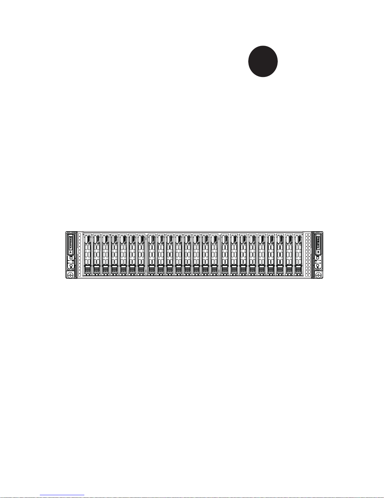
SuperServer
2026TT-DLRF
2026TT-DLIBXRF
2026TT-DLIBQRF

The information in this User’s Manual has been carefully reviewed and is believed to be accurate.
The vendor assumes no responsibility for any inaccuracies that may be contained in this document,
makes no commitment to update or to keep current the information in this manual, or to notify any
person or organization of the updates. Please Note: For the most up-to-date version of this
manual, please see our web site at www.supermicro.com.
Super Micro Computer, Inc. ("Supermicro") reserves the right to make changes to the product
described in this manual at any time and without notice. This product, including software and documentation, is the property of Supermicro and/or its licensors, and is supplied only under a license.
Any use or reproduction of this product is not allowed, except as expressly permitted by the terms
of said license.
IN NO EVENT WILL SUPERMICRO BE LIABLE FOR DIRECT, INDIRECT, SPECIAL, INCIDENTAL,
SPECULATIVE OR CONSEQUENTIAL DAMAGES ARISING FROM THE USE OR INABILITY TO
USE THIS PRODUCT OR DOCUMENTATION, EVEN IF ADVISED OF THE POSSIBILITY OF
SUCH DAMAGES. IN PARTICULAR, SUPERMICRO SHALL NOT HAVE LIABILITY FOR ANY
HARDWARE, SOFTW ARE, OR DA TA STORED OR USED WITH THE PRODUCT, INCLUDING THE
COSTS OF REPAIRING, REPLACING, INTEGRATING, INSTALLING OR RECOVERING SUCH
HARDWARE, SOFTWARE, OR DATA.
Any disputes arising between manufacturer and customer shall be governed by the laws of Santa
Clara County in the State of California, USA. The State of California, County of Santa Clara shall
be the exclusive venue for the resolution of any such disputes. Super Micro's total liability for all
claims will not exceed the price paid for the hardware product.
FCC Statement: This equipment has been tested and found to comply with the limits for a Class A
digital device pursuant to Part 15 of the FCC Rules. These limits are designed to provide reasonable
protection against harmful interference when the equipment is operated in a commercial environment. This equipment generates, uses, and can radiate radio frequency energy and, if not installed
and used in accordance with the manufacturer’s instruction manual, may cause harmful interference
with radio communications. Operation of this equipment in a residential area is likely to cause harmful
interference, in which case you will be required to correct the interference at your own expense.
California Best Management Practices Regulations for Perchlorate Materials: This Perchlorate warning applies only to products containing CR (Manganese Dioxide) Lithium coin cells. “Perchlorate
Material-special handling may apply. See www.dtsc.ca.gov/hazardouswaste/perchlorate”
WARNING: Handling of lead solder materials used in this
product may expose you to lead, a chemical known to the
State of California to cause birth defects and other reproductive harm.
Manual Revision 1.0
Release Date: June 28, 2011
Unless you request and receive written permission from Super Micro Computer, Inc., you may not
copy any part of this document.
Information in this document is subject to change without notice. Other products and companies
referred to herein are trademarks or registered trademarks of their respective companies or mark
holders.
Copyright © 2011 by Super Micro Computer, Inc.
All rights reserved.
Printed in the United States of America
Preface
About This Manual
This manual is written for professional system integrators and PC technicians. It
provides information for the installation and use of the SuperServer 2026TT-DLRF/
DLIBXRF/DLIBQRF. Installation and maintenance should be performed by experienced technicians only.
The SuperServer 2026TT-DLRF/DLIBXRF/DLIBQRF is a 2U Twin (two serverboards/nodes in a 2U chassis) rackmount server based on the SC217HD-R1400BP
server chassis and two Super X8DTT-HEF+/X8DTT-HIBXF+/X8DTT-HIBQF+
serverboards.
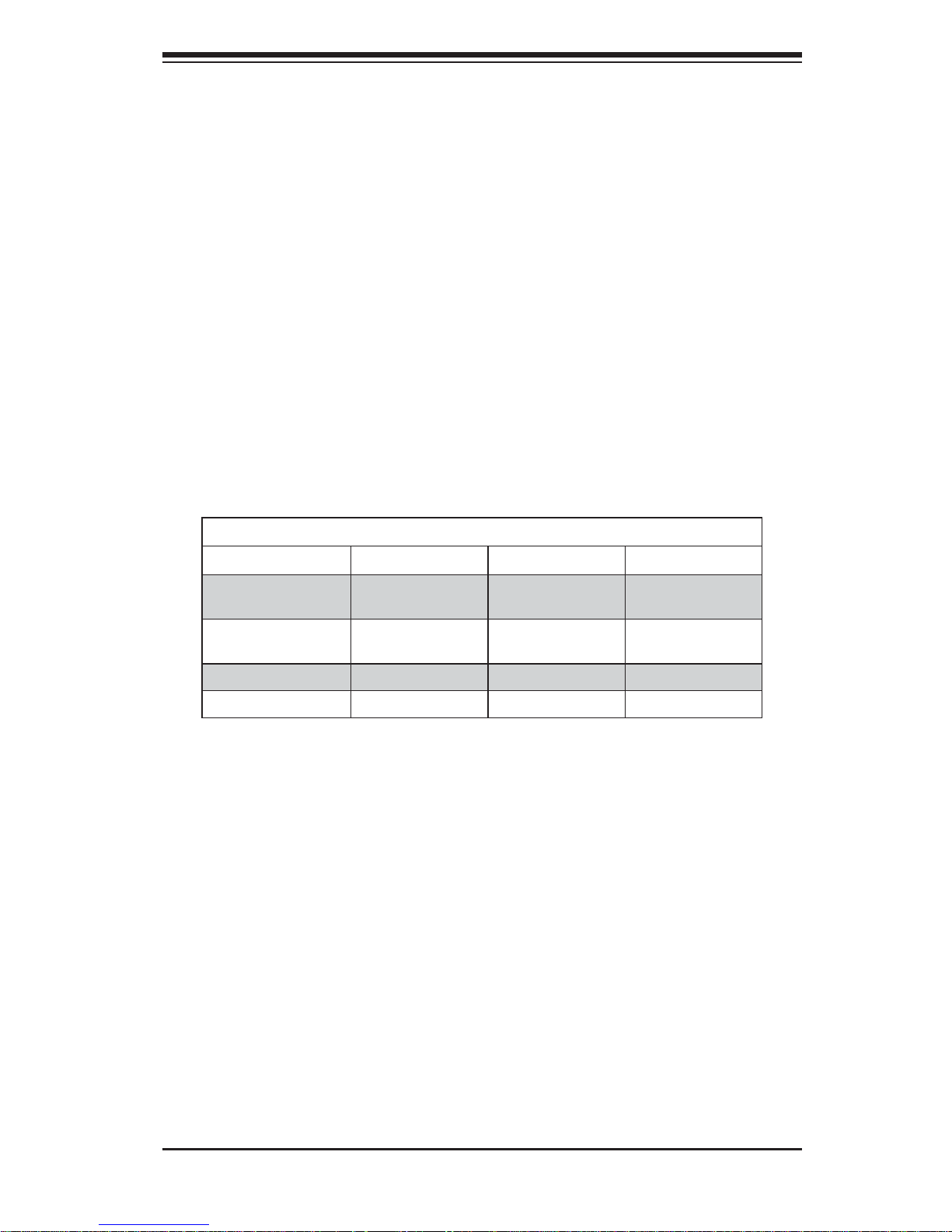
The main differences between the various serverboards and the servers they are
in is shown in the table below:
Model Variations (Differences between X8DTT-x Models)
X8DTT-HEF+ X8DTT-HIBXF+ X8DTT-HIBQF+
IPMI 2.0 w/ KVM
Over LAN
Yes Yes Yes
Infi niBand
Connection
No Yes Yes
DDR IB
No Yes No
QDR IB
No No Yes
Manual Organization
Chapter 1: Introduction
The fi rst chapter provides a checklist of the main components included with the
server system and describes the main features of the Super X8DTT-HEF+/X8DTTHIBXF+/X8DTT-HIBQF+ serverboard and the SC217HD-R1400BP chassis.
Chapter 2: Server Installation
This chapter describes the steps necessary to install the SuperServer 2026TTDLRF/DLIBXRF/DLIBQRF into a rack and check out the server confi guration prior
to powering up the system. If your server was ordered without the processor and
memory components, this chapter will refer you to the appropriate sections of the
manual for their installation.
iii
Preface

iv
Chapter 3: System Interface
Refer to this chapter for details on the system interface, which includes the functions
and information provided by the control panel on the chassis as well as other LEDs
located throughout the system.
Chapter 4: System Safety
You should thoroughly familiarize yourself with this chapter for a general overview
of safety precautions that should be followed when installing and servicing the
SuperServer 2026TT-DLRF/DLIBXRF/DLIBQRF.
Chapter 5: Advanced Serverboard Setup
Chapter 5 provides detailed information on the X8DTT-HEF+/X8DTT-HIBXF+/
X8DTT-HIBQF+ serverboard, including the locations and functions of connectors,
headers and jumpers. Refer to this chapter when adding or removing processors
or main memory and when reconfi guring the serverboard.
Chapter 6: Advanced Chassis Setup
Refer to Chapter 6 for detailed information on the SC217HD-R1400BP 2U rackmount server chassis. You should follow the procedures given in this chapter when
installing, removing or reconfi guring SATA or peripheral drives and when replacing
system power supply units and cooling fans.
Chapter 7: BIOS
The BIOS chapter includes an introduction to BIOS and provides detailed information on running the CMOS Setup Utility.
Appendix A: BIOS Error Beep Codes
Appendix B: System Specifi cations
SUPERSERVER 2026TT-DLRF/DLIBXRF/DLIBQRF User's Manual

v
Preface
Notes

vi
Table of Contents
Chapter 1 Introduction
1-1 Overview .........................................................................................................1-1
1-2 Serverboard Features .....................................................................................1-2
Processors ......................................................................................................1-2
Memory ...........................................................................................................1-2
SAS .................................................................................................................1-2
SATA ................................................................................................................1-2
PCI Expansion Slots .......................................................................................1-2
Ethernet Ports .................................................................................................1-2
Onboard Controllers/Ports ..............................................................................1-3
Graphics Controller .........................................................................................1-3
Other Features ................................................................................................1-3
Infi niBand ........................................................................................................1-3
1-3 Server Chassis Features ................................................................................1-5
System Power ................................................................................................. 1-5
SAS/SATA Subsystem .....................................................................................1-5
Control Panel .................................................................................................. 1-5
Rear I/O ...........................................................................................................1-5
Cooling System ...............................................................................................1-5
1-4 2U Twin: System Notes ...................................................................................1-6
Nodes ..............................................................................................................1-6
System Power ................................................................................................. 1-6
SAS/SATA Backplane/Drives .......................................................................... 1-6
1-5 Contacting Supermicro ....................................................................................1-7
Chapter 2 Server Installation
2-1 Overview .........................................................................................................2-1
2-2 Unpacking the System .................................................................................... 2-1
2-3 Preparing for Setup ......................................................................................... 2-1
Choosing a Setup Location ............................................................................. 2-2
Rack Precautions ............................................................................................ 2-2
Server Precautions .......................................................................................... 2-2
Rack Mounting Considerations ....................................................................... 2-3
Ambient Operating Temperature ................................................................ 2-3
Reduced Airfl ow ......................................................................................... 2-3
Mechanical Loading ................................................................................... 2-3
Circuit Overloading ..................................................................................... 2-3
SUPERSERVER 2026TT-DLRF/DLIBXRF/DLIBQRF User's Manual

vii
Table of Contents
Reliable Ground ......................................................................................... 2-3
Removing the Protective Film ......................................................................... 2-4
2-4 Rack Mounting Instructions ............................................................................. 2-5
Separating the Sections of the Rack Rails ..................................................... 2-5
Installing The Inner Rails on the Chassis ....................................................... 2-6
Installing the Outer Rails on the Rack ............................................................ 2-7
Standard Chassis Installation .........................................................................2-8
2-5 Checking the Serverboard Setup .................................................................... 2-9
2-6 Preparing to Power On ................................................................................. 2-10
Chapter 3 System Interface
3-1 Overview .........................................................................................................3-1
3-2 Control Panel Buttons ..................................................................................... 3-1
Power ..............................................................................................................3-1
UID ..................................................................................................................3-1
3-3 Control Panel LEDs ........................................................................................ 3-2
Alert LED .........................................................................................................3-2
NIC ..................................................................................................................3-2
3-4 Hard Drive Carrier LEDs ................................................................................. 3-3
Chapter 4 System Safety
4-1 Electrical Safety Precautions .......................................................................... 4-1
4-2 General Safety Precautions ............................................................................ 4-2
4-3 ESD Precautions ............................................................................................. 4-3
4-4 Operating Precautions .................................................................................... 4-4
Chapter 5 Advanced Serverboard Setup
5-1 Handling the Serverboard ............................................................................... 5-1
Precautions .....................................................................................................5-1
5-2 I/O Ports ..........................................................................................................5-2
Unpacking .......................................................................................................5-2
5-3 Processor and Heatsink Installation................................................................5-3
Installing LGA1366 Processors ....................................................................... 5-3
Installing a CPU Heatsink ............................................................................... 5-5
Removing the Heatsink ................................................................................... 5-6
5-4 Installing Memory ............................................................................................ 5-7
5-5 Adding PCI Expansion Cards ......................................................................... 5-9
5-6 Serverboard Details ...................................................................................... 5-10
X8DTT-H+ Series Quick Reference ...............................................................5-11
5-7 Connector Defi nitions .................................................................................... 5-12
5-8 Jumper Settings ............................................................................................5-16

viii
5-9 Onboard Indicators ........................................................................................5-18
5-10 SAS/SATA Ports ............................................................................................5-19
5-11 Installing Additional Drivers ...........................................................................5-20
5-12 Confi guring Super Doctor III ......................................................................... 5-21
Chapter 6 Advanced Chassis Setup
6-1 Static-Sensitive Devices ..................................................................................6-1
Precautions .....................................................................................................6-1
Unpacking .......................................................................................................6-1
6-2 Control Panel ..................................................................................................6-2
6-3 System Fans ...................................................................................................6-2
Fan Confi guration ............................................................................................ 6-3
System Fan Failure ......................................................................................... 6-3
6-4 Hard Drive Installation/Removal......................................................................6-4
Overview .........................................................................................................6-4
Installing and Removing Hard Drives ............................................................. 6-4
6-5 Node Installation/Removal ..............................................................................6-7
6-6 Installing the Air Shrouds ................................................................................ 6-9
Air Shrouds ..................................................................................................... 6-9
6-7 Power Supply .................................................................................................. 6-9
Chapter 7 BIOS
7-1 Introduction ......................................................................................................7-1
Starting BIOS Setup Utility .............................................................................. 7-1
How To Change the Confi guration Data .........................................................7-1
Starting the Setup Utility ................................................................................. 7-2
7-2 Main Setup ...................................................................................................... 7-2
7-3 Advanced Setup Confi gurations...................................................................... 7-4
7-4 Security Settings ...........................................................................................7-23
7-5 Boot Confi guration ........................................................................................ 7-24
7-6 Exit Options ................................................................................................... 7-26
7-7 BIOS Recovery ............................................................................................. 7-26
How to Recover the AMIBIOS Image (the Main BIOS Block) ...................... 7-27
Boot Sector Recovery from a USB Device .............................................. 7-27
Boot Sector Recovery from an IDE CD-ROM .......................................... 7-27
Boot Sector Recovery from a Serial Port ("Serial Flash") ....................... 7-28
Appendix A BIOS Error Beep Codes
A-1 BIOS Error Beep Codes ................................................................................. A-1
Appendix B System Specifi cations
SUPERSERVER 2026TT-DLRF/DLIBXRF/DLIBQRF User's Manual

Chapter 1
Introduction
1-1 Overview
The SuperServer 2026TT-DLRF/DLIBXRF/DLIBQRF is a "2U Twin" server comprised of the SC217HD-R1400BP 2U chassis and two X8DTT-HEF+/X8DTTHIBXF+/X8DTT-HIBQF+ serverboards. See the list below for the serverboard
included in each server model.
In addition to the serverboard and chassis, various hardware components may have
been included with the system, as listed below.
Four passive CPU heatsinks (SNK-P0038PS)•
Four 8-cm cooling fans (FAN-0111L4)•
Two air shrouds (MCP-310-82708-0B)•
SAS/SATA Accessories: •
Twenty four 2.5" hard drive carriers (twelve per node) (MCP-220-00047-0B)
One internal HDD backplane (BPN-SAS-217D)
Two PCI Express riser cards (RSC-R2UT-2E8R)•
Rackmount rails kit (MCP-290-00053-0N)•
One CD containing drivers and utilities•
2026TT-DLRF/DLIBXRF/DLIBQRF User's Manual•
Note: These servers do not require the use of SAS/SATA cables.
Chapter 1: Introduction
1-1

1-2
SUPERSERVER 2026TT-DLRF/DLIBXRF/DLIBQRF User's Manual
1-2 Serverboard Features
The 2026TT-DLRF/DLIBXRF/DLIBQRF includes two X8DTT series dual processor
serverboards (see list on previous page), which are based on Intel's 5520 + ICH10R
chipset. Below are the main features of the serverboards. Note that the features on
each board are doubled for the server, which includes two nodes.
Processors
Each X8DTT series serverboard supports two Intel® 5600/5500 series processors
in LGA1366 sockets. Please refer to our web site for a complete listing of supported
processors (www.supermicro.com).
Memory
Each X8DTT has twelve DIMM sockets that can support up to 192 GB of registered ECC DDR3-1333/1066/800 SDRAM or 48 GB of unbuffered ECC/Non-ECC
1333/1066/800 MHz memory for a maximum of 768 GB for the system. See Chapter
5 Section 6 for more details on installing memory into the system.
SAS
An LSI 2008 SAS daughter card may be included with the system to provide support
for six SAS drives per node. The hot-swap SAS drives are connected to a backplane
that provides power, bus termination and confi guration settings.
SATA
SATA may be supp orted w ith a SATA daug hter card (inste ad of a SAS daughter
card) fo r six Gb/s S ATA dri ves. The hot-swappable SATA drives are connected to
a backplane that provides power, bus termination and confi guration settings.
PCI Expansion Slots
Each X8DTT-HEF+/X8DTT-HIBXF+/X8DTT-HIBQF+ has included riser cards that
allow it to support two full-sized PCI Express 2.0 x8 expansion cards (in x16 slots),
or four total for the server.
Ethernet Ports
An Intel® network controller is integrated into each of the serverboards to support
two Gigabit LAN ports (100/1000Base-T/1000BaseTX, RJ45 output).

Chapter 1: Introduction
1-3
Onboard Controllers/Ports
Onboard I/O backpanel ports on each serverboard include one COM port, a VGA
port, two USB ports, a dedicated IPMI LAN port and two Gigabit LAN (NIC) ports. An
Infi niBand port is also included on the X8DTT-H IBXF+/HI BQF+ serverboards (the
2026TT-HIBXRF, 2026TT-HIBQRF, 2026TT-H6IBXRF and 2026TT-H6IBQRF only).
Up to four U SB 2.0 (U nivers al Ser ial Bus) conn ecti ons (2 Rear US B Por ts and 1
T ype A Header w/2 USB connections supported) are on each of the servers. There
are two sets of I/O ports included in the server (one set for each serverboard).
Graphics Controller
The X8DTT-HF+/X8DTT-HIBXF+/X8DTT-HIBQF+ features an integrated Matrox
G200eW graphics chip, which includes 16 MB of DDR2 memory.
Other Features
Other onboard features that promote system health include voltage monitors, autoswitching voltage regulators, chassis and CPU overheat sensors, virus protection
and BIOS rescue.
Infi niBand
The 2026TT-DLRF/DLIBXRF/DLIBQRF include an Infi niBand port at DDR (dual
data rate) and QD R (quad dat a r ate) speed s, re s pe c t ive ly. Infi niBand is a scalable
serial communications link intended for connecting processors with high-speed
peripherals. (Infi niBand requires a QSFP connector.)
1-4
SUPERSERVER 2026TT-DLRF/DLIBXRF/DLIBQRF User's Manual
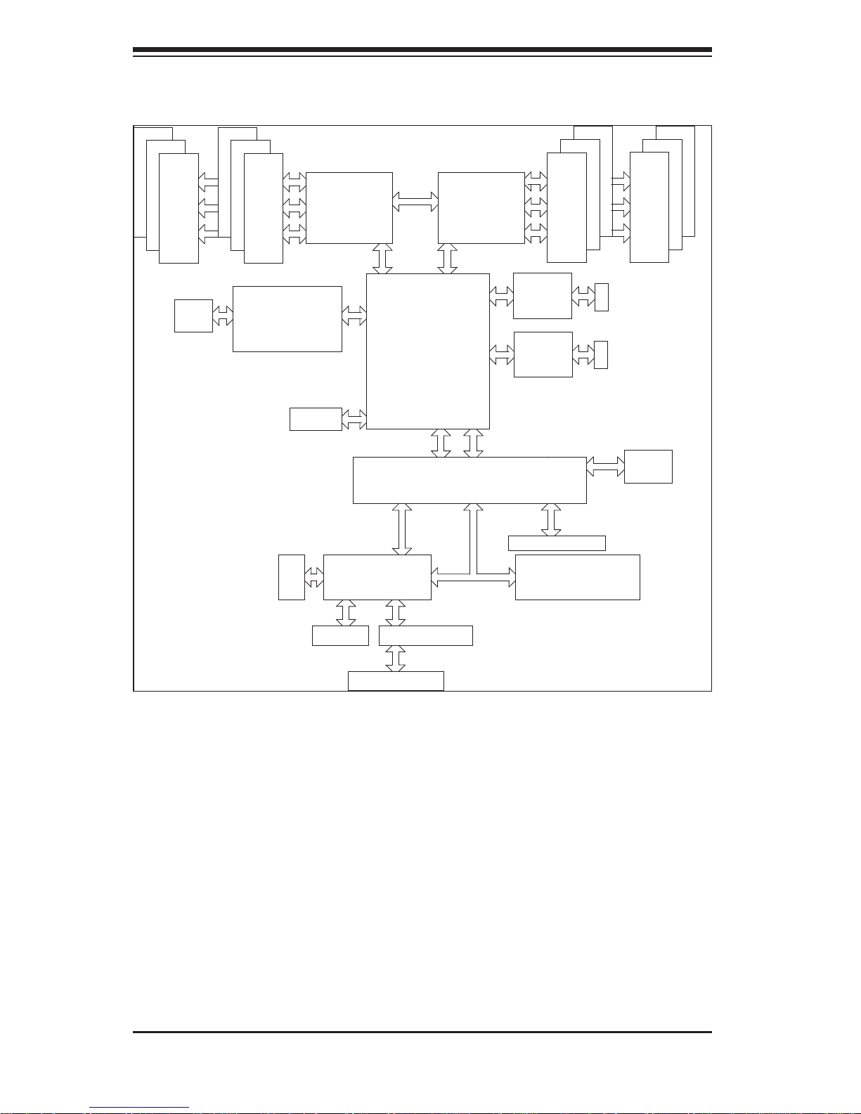
Figure 1-1. Intel 5520 Chipset:
System Block Diagram
Note1: This is a general block diagram. Please see Chapter 5 for details.
PROCESSOR#0
#1
#1
#1
#2
DDR3 DIMM
#2
#2
DDR3 DIMM
#1
#1
#1
DDR3 DIMM
#2
#2
#2
DDR3 DIMM
C
C
A
A
B
B
DD
E
E
FF
IOH
5520/5500
36-D/24-D
ICH10R
Intel
82574
BMC/VGA
VGA CONN
DDR II
PCI
4 SATA
LPC
SPI
AT25
DF321
MT25408
Connect-X IB
PCI-E Gen2/DDR or QDR
(For 36D Only)
QSFP
RTL8201N PHY
Dedicated LAN
LPCIO W83527
RMII
PCI-E
x16 Slot
Hotswap Connector
Intel
82574
PROCESSOR#1
RJ-45
RJ-45
QPI

Chapter 1: Introduction
1-5
1-3 Server Chassis Features
The following is a general outline of the main features of the SC217HD-R1400BP
2U chassis. Details on the chassis can be found in Chapter 6.
System Power
The SC217HD-R1400BP includes a redundant (dual) 1400W power supply, which
provides power to both serverboards (nodes). If either power supply fails, the other
will allow the system to continue to run.
SAS/SATA Subsystem
The SC217HD cha ssis was desi gned to suppo rt 24 2.5 " SAS/SATA h ard drives,
which a re hot- swappa ble unit s. Twelve hard dri ves are as signe d to each n ode in
the system.
Control Panel
The SC217HD-R1400BP features two independant control panels. Each control
panel has LEDs to indicate power on, network activity, power fail, fan fail, system
overheat conditions and the UID LED for its own specifi c node. Each control panel
also includes a main power button and a UID button.
Rear I/O
Each node provides slots for two low-profi le PCI Express x16 expansion cards and
includes one COM port, two USB ports, one VGA port, two Gb Ethernet ports and
one dedicated IPMI (LAN) port. See Chapter 6 for details.
Cooling System
The chassis has an innovative cooling design that features four 8-cm high-performance fans. A fan speed control setting in BIOS allows fan speed to be determined
by system temperature. See Chapter 6 for details.

1-6
SUPERSERVER 2026TT-DLRF/DLIBXRF/DLIBQRF User's Manual
1-4 2U Twin: System Notes
As a 2U Twin confi guration, the 2026TT-DLxRF series is a unique server system.
With two system boards incorporated into a single chassis acting as two separate
nodes, there are several points you should keep in mind.
Nodes
Each of the two serverboards act as a separate node in the system. As independant
nodes, each may be powered off and on without affecting the others. In addition,
each node is a hot-swappable unit that may be removed from the rear of the chassis.
The nodes are connected to the server backplane by means of an adapter card.
System Power
The server has an additional 1400W power supply module (two total) for power
redundancy. If a power supply module fails the other backup module will keep the
system running until it can be replaced.
SAS/SATA Backplane/Drives
As a system, the 2026TT-DLxRF supports the use of 24 SAS or SATA drives. A
single backplane works to apply system-based control for power and fan speed
functions, yet at the same time logically connects a set of 12 drives to each
serverboard..

Chapter 1: Introduction
1-7
1-5 Contacting Supermicro
Headquarters
Address: Super Micro Computer, Inc.
980 Rock Ave.
San Jose, CA 95131 U.S.A.
Tel: +1 (408) 503-8000
Fax: +1 (408) 503-8008
Email: marketing@supermicro.com (General Information)
support@supermicro.com (Technical Support)
Web Site: www.supermicro.com
Europe
Address: Super Micro Computer B.V.
Het Sterrenbeeld 28, 5215 ML
's-Hertogenbosch, The Netherlands
Tel: +31 (0) 73-6400390
Fax: +31 (0) 73-6416525
Email: sales@supermicro.nl (General Information)
support@supermicro.nl (Technical Support)
rma@supermicro.nl (Customer Support)
Asia-Pacifi c
Address: Super Micro Computer, Inc.
4F, No. 232-1, Liancheng Rd.
Chung-Ho 235, Taipei County
Taiwan, R.O.C.
Tel: +886-(2) 8226-3990
Fax: +886-(2) 8226-3991
Web Site: www.supermicro.com.tw
Technical Support:
Email: support@supermicro.com.tw
Tel: 886-2-8226-5990

1-8
SUPERSERVER 2026TT-DLRF/DLIBXRF/DLIBQRF User's Manual
Notes
Chapter 2: Server Installation
2-1
Chapter 2
Server Installation
2-1 Overview
This chapter provides a quick setup checklist to get the 2026TT-DLxRF up and
running. Following these steps in the order given should enable you to have the
system operational within a minimum amount of time. This quick setup assumes
that your system has come to you with the processors and memory preinstalled. If
your system is not already fully integrated with a serverboard, processors, system
memory etc., please turn to the chapter or section noted in each step for details on
installing specifi c components.
2-2 Unpacking the System
You should inspect the box the system was shipped in and note if it was damaged
in any way. If the server itself shows damage you should fi le a damage claim with
the carrier who delivered it.
Decide on a suitable location for the rack unit that will hold the server. It should be
situated in a clean, dust-free area that is well ventilated. Avoid areas where heat,
electrical noise and electromagnetic fi elds are generated. You will also need it placed
near a grounded power outlet. Be sure to read the Rack and Server Precautions
in the next section.
2-3 Preparing for Setup
The box the server was shipped in should include the rackmount hardware needed
to install the system into the rack. Follow the steps in the order given to complete
the installation process in a minimum amount of time. Please read this section in
its entirety before you begin the installation procedure outlined in the sections that
follow.

2-2
SUPERSERVER 2026TT-DLRF/DLIBXRF/DLIBQRF User's Manual
Choosing a Setup Location
Leave enough clearance in front of the rack to enable you to open the front •
door completely (~25 inches).
Leave approximately 30 inches of clearance in the back of the rack to allow for
•
suffi cient airfl ow and ease in servicing.
This product is for installation only in a Restricted Access Location (dedicated •
equipment rooms, service closets and the like).
This product is not suitable for use with visual display work place devices accord-•
ing to §2 of the the German Ordinance for Work with Visual Display Units.
!
!
Warnings and Precautions!
Rack Precautions
Ensure that the leveling jacks on the bottom of the rack are fully extended to •
the fl oor with the full weight of the rack resting on them.
In single rack installation, stabilizers should be attached to the rack.•
In multiple rack installations, the racks should be coupled together.•
Always make sure the rack is stable before extending a component from it.•
You should extend only one component at a time - extending two or more si-•
multaneously may cause the rack to become unstable.
Server Precautions
Review the electrical and general safety precautions in Chapter 4.•
Determine the placement of each component in the rack • before you install the
rails.
Install the heaviest server components on the bottom of the rack fi rst, and then •
work up.
Use a regulating uninterruptible power supply (UPS) to protect the server from •
power surges, voltage spikes and to keep your system operating in case of a
power failure.

Chapter 2: Server Installation
2-3
Allow the hot plug hard drives and power supply modules to cool before touch-•
ing them.
Always keep the rack's front door and all panels and components on the servers •
closed when not servicing to maintain proper cooling.
Make sure all power and data cables are properly connected and not blocking
•
the chassis airfl ow. See Chapter 5 for details on cable connections.
Rack Mounting Considerations
Ambient Operating Temperature
If installed in a closed or multi-unit rack assembly, the ambient operating temperature of the rack environment may be greater than the ambient temperature of the
room. Therefore, consideration should be given to installing the equipment in an
environment compatible with the manufacturer’s maximum rated ambient temperature (Tmra).
Reduced Airfl ow
Equipment should be mounted into a rack so that the amount of airfl ow required
for safe operation is not compromised.
Mechanical Loading
Equipment should be mounted into a rack so that a hazardous condition does not
arise due to uneven mechanical loading.
Circuit Overloading
Consideration should be given to the connection of the equipment to the power
supply circuitry and the effect that any possible overloading of circuits might have
on overcurrent protection and power supply wiring. Appropriate consideration of
equipment nameplate ratings should be used when addressing this concern.
Reliable Ground
A reliable ground must be maintained at all times. To ensure this, the rack itself
should be grounded. Particular attention should be given to power supply connections other than the direct connections to the branch circuit (i.e. the use of power
strips, etc.).
2-4
SUPERSERVER 2026TT-DLRF/DLIBXRF/DLIBQRF User's Manual
!
Warning: Except for short periods of time, do NOT operate the server
without the cover in place. The chassis cover must be in place to
allow proper airfl ow and prevent overheating.
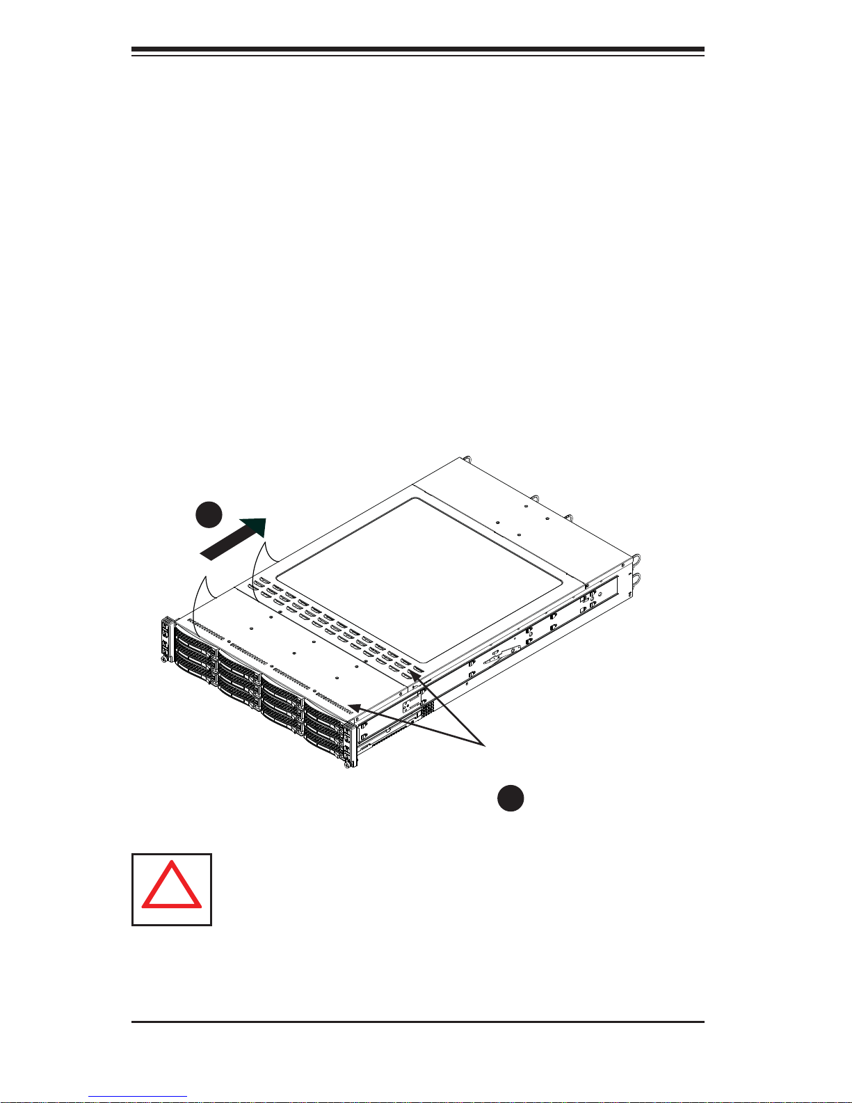
Removing the Protective Film
Before operating the server for the fi rst time, it is important to remove the protec-
tive fi lm covering the top of the chassis, in order to allow for proper ventilation and
cooling.
Removing the Protective Film
Peel off the protective fi lm covering the top cover and the top of the chassis1.
Check that all ventilation openings on the top cover and the top of the chassis 2.
are clear and unobstructed.
Figure 2-1: Removing the Protective Film
Check Ventilation
Openings
1
1
1
2
Chapter 2: Server Installation
2-5
2-4 Rack Mounting Instructions
This section provides information on installing the SC217 chassis into a rack unit
with the quick-release rails provided. There are a variety of rack units on the market,
which may mean the assembly procedure will differ slightly. Y ou should also refer to
the installation instructions that came with the rack unit you are using.
Note: This rail will fi t a rack between 26" and 33.5" deep.
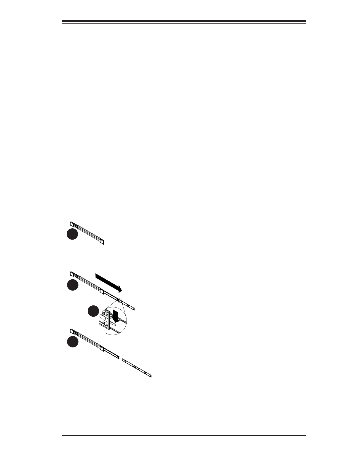
Separating the Sections of the Rack Rails
The chassis package includes two rail assemblies in the rack mounting kit. Each
assembly consists of two sections: an inner fi xed chassis rail that secures directly
to the server chassis and an outer fi xed rack rail that secures directly to the rack
itself.
Figure 2-2. Separating the Rack Rails
1
1
1
2
1
4
1
3
Separating the Inner and Outer Rails
Locate the rail assembly in the chassis 1.
packaging.
Extend the rail assembly by pulling it 2.
outward.
Press the quick-release tab.3.
Separate the inner rail extension from 4.
the outer rail assembly.
Rail Assembly
Extending the Rails
Quick-
Release Tab
Separating
the Inner Rail
Extension
2-6
SUPERSERVER 2026TT-DLRF/DLIBXRF/DLIBQRF User's Manual
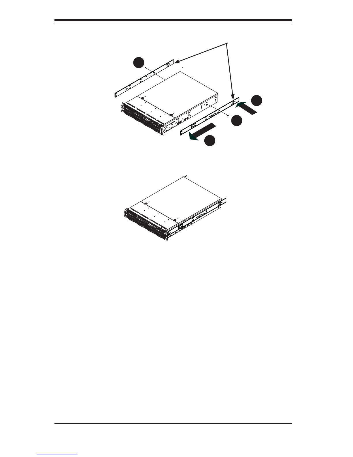
Figure 2-3: Installing the Inner Rails
Figure 6-3: Installing the Inner Rails
Installing The Inner Rails on the Chassis
Installing the Inner Rails
Confi rm that the left and right inner rails have been correctly identifi ed.1.
Place the inner rail fi rmly against the side of the chassis, aligning the hooks 2.
on the side of the chassis with the holes in the inner rail.
Slide the inner rail forward toward the front of the chassis until the rail clicks 3.
into the locked position, which secures the inner rail to the chassis.
Secure the inner rail to the chassis with the screws provided. 4.
Repeat steps 1 through 4 above for the other inner rail.5.
1
3
1
4
1
4
1
2
Inner Rails
Chapter 2: Server Installation
2-7
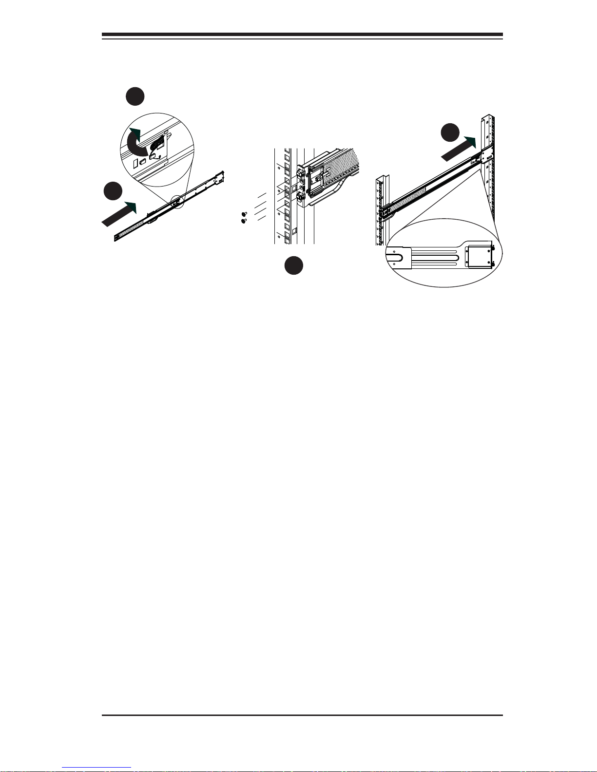
Installing the Outer Rails on the Rack
Installing the Outer Rails
Press upward on the locking tab at the rear end of the middle rail. 1.
Push the middle rail back into the outer rail.2.
Hang the hooks of the front of the outer rail onto the slots on the front of 3.
the rack. If necessary, use screws to secure the outer rails to the rack, as
illustrated above.
Pull out the rear of the outer rail, adjusting the length until it fi ts within the 4.
posts of the rack.
Hang the hooks of the rear portion of the outer rail onto the slots on the rear 5.
of the rack. If necessary, use screws to secure the rear of the outer rail to the
rear of the rack.
Repeat steps 1-5 for the remaining outer rail.6.
Figure 6-5: Extending and Releasing the Outer Rails
1
1
1
2
1
3
1
4
2-8
SUPERSERVER 2026TT-DLRF/DLIBXRF/DLIBQRF User's Manual
Figure 6-6: Installing into a Rack
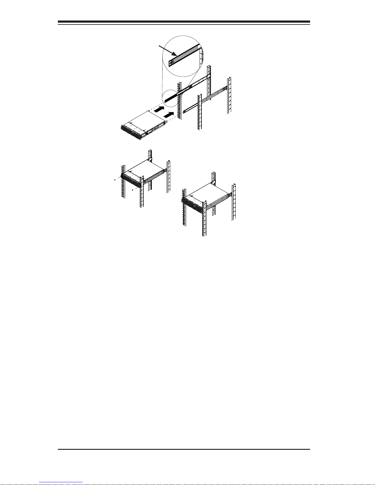
Standard Chassis Installation
Installing the Chassis into a Rack
Confi rm that the inner rails are properly installed on the chassis. 1.
Confi rm that the outer rails are correctly installed on the rack. 2.
Pull the middle rail out from the front of the outer rail and make sure that the 3.
ball-bearing shuttle is at the front locking position of the middle rail.
Align the chassis inner rails with the front of the middle rails.4.
Slide the inner rails on the chassis into the middle rails, keeping the pressure 5.
even on both sides, until the locking tab of the inner rail clicks into the front of
the middle rail, locking the chassis into the fully extended position.
Depress the locking tabs of both sides at the same time and push the chassis 6.
all the way into the rear of the rack.
If necessary for security purposes, use screws to secure the chassis handles 7.
to the front of the rack.
Ball-Bearing
Shuttle

Chapter 2: Server Installation
2-9
2-5 Checking the Serverboard Setup
After you install the system in the rack, you will need to access the inside of the
nodes to make sure the serverboard is properly installed.
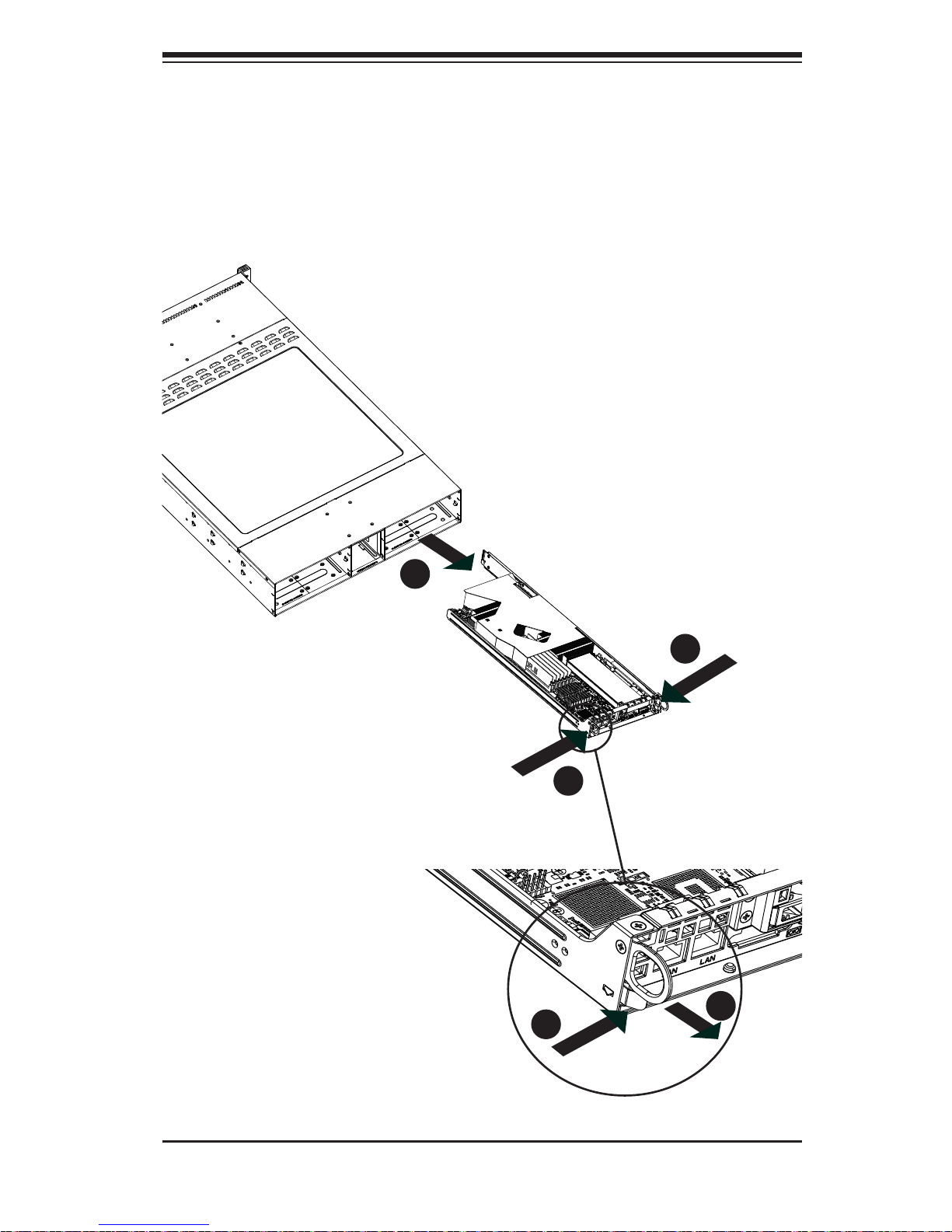
Accessing the Inside of a Node (Figure 2-6)
Make sure the protective fi lm on the cover has been removed as described in 1.
the previous section.
Before removing a node, unplug all the cables that connect to that node.2.
To remove a node, fi rst push the two latches (located near the handles) 3.
inward.
Grasp the handles and pull the node out from the rear of the chassis.4.
To remove the system from the rack completely, depress the locking tabs in 5.
the chassis rails (push the right-side tab down and the left-side tab up) to
continue to pull the system out past the locked position.
Checking the Components and Setup
You may have one or two processors already installed in each of the 1.
serverboards. Each processor needs its own heatsink. See Chapter 5 for
instructions on processor and heatsink installation.
Your server system may have come with system memory already installed. 2.
Make sure all DIMMs are fully seated in their slots. For details on adding
system memory, refer to Chapter 5.
You can install four add-on cards to the system (two for each node). See 3.
Chapter 5 for details on installing PCI add-on cards.
Make sure all power and data cables are properly connected and not blocking 4.
the chassis airfl ow. See Chapter 5 for details on cable connections.

2-10
SUPERSERVER 2026TT-DLRF/DLIBXRF/DLIBQRF User's Manual
2-6 Preparing to Power On
Next, you should check to make sure the hard drives and the backplane have been
properly installed and all connections have been made.
Checking the Hard Drives
The hard disk drives are accessable from the front of the server and can be 1.
installed and removed from the front of the chassis without removing the top
chassis cover.
Depending upon your system's confi guration, your system may have one or 2.
more drives already installed. If you need to install hard drives, please refer to
Chapter 6.
Checking the Airfl ow
Airfl ow is provided by four 8-cm PWM fans and (for each serverboard) one 1.
air shroud. The system component layout was carefully designed to direct
suffi cient cooling airfl ow to the components that generate the most heat.
Note that all power and data cables have been routed in such a way that they 2.
do not block the airfl ow generated by the fans.
Providing Power
Plug the power cords from the power supplies unit into a high-quality power 1.
strip that offers protection from electrical noise and power surges.
It is recommended that you use an uninterruptible power supply (UPS).2.
Finally, depress the power on button on the front of the chassis.3.
Chapter 2: Server Installation
2-11
Figure 2-6. Removing a Node from the System
1
1
1
1
1
2
1
2
1
1

2-12
SUPERSERVER 2026TT-DLRF/DLIBXRF/DLIBQRF User's Manual
Notes
Chapter 3: System Interface
3-1
Chapter 3
System Interface
3-1 Overview
There are LEDs on the control panels and on the hard drive carriers to keep you
constantly informed of the overall status of the system as well as the activity and
health of specifi c components. There are also two buttons on each control panel.
This chapter explains the meanings of all LED indicators and the appropriate response you may need to take. Note that the server has two control panels, one
for each serverboard (node) installed in the system. This allows each node to be
controlled independently of the other.
3-2 Control Panel Buttons
There are two push-buttons located on each control panel: a power on/off button
and a UID button.
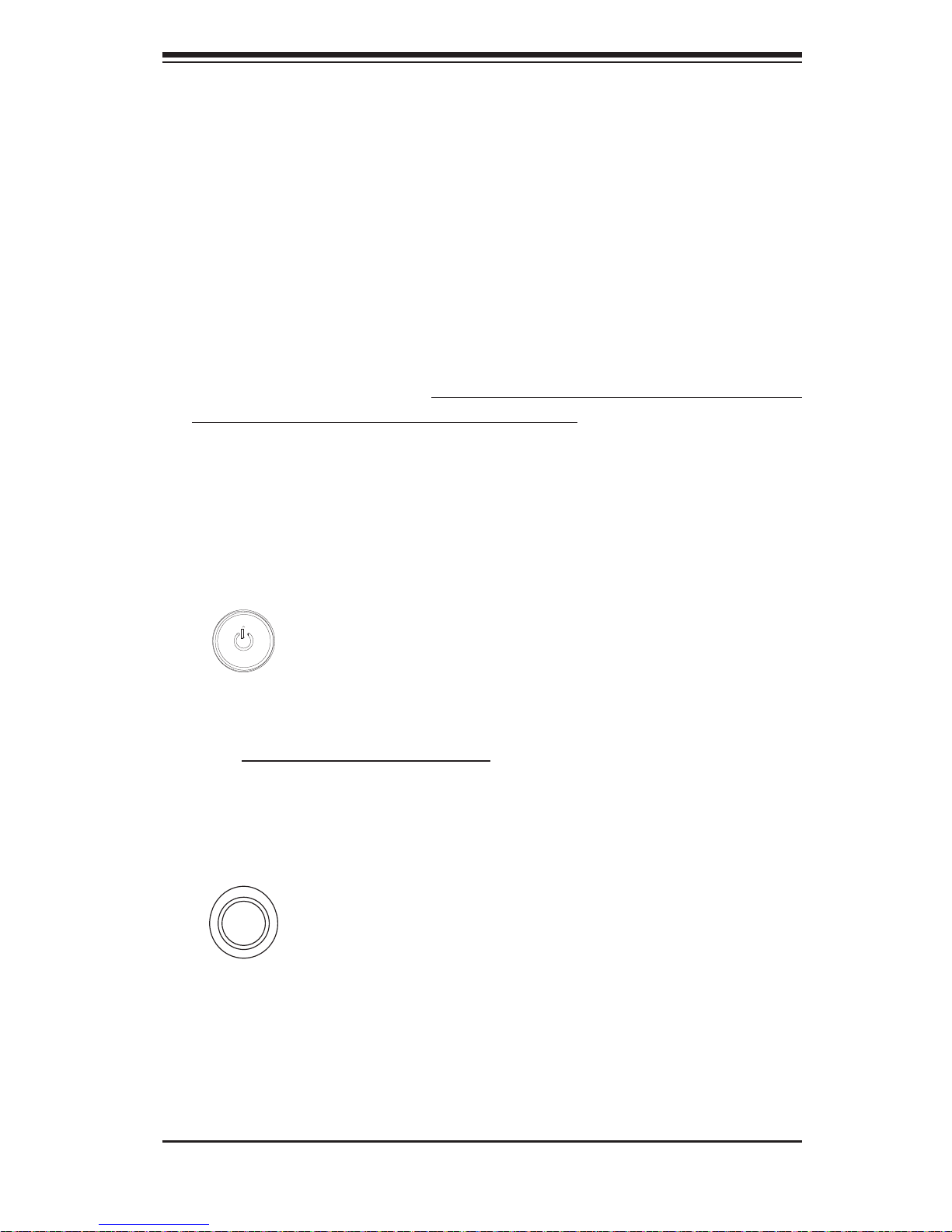
Power
This is the main power button, which is used to apply or turn off the main system
power only to the node it is connected to. Depressing this button removes the main
power but keeps standby power supplied to the serverboard. Therefore, you must
unplug the AC power cord from any external power source before servicing. This
button has an LED built into it, which will illuminate when its node is powered on.
UID
Depressing the UID (unit identifi er) button illuminates an LED on both the front and
rear of the chassis for easy system location in large stack confi gurations. The LED
will remain on until the button is pushed a second time. Another UID button on the
rear of the chassis serves the same function. This button has an LED built into it,
which will illuminate when either the front or rear UID button is pushed.
3-2
SUPERSERVER 2026TT-DLRF/DLIBXRF/DLIBQRF User's Manual
3-3 Control Panel LEDs
In addition to the LEDs built into the power and UID buttons, each of the control
panels located on the front of the SC217 chassis has two LEDs that provide you
with critical information related their own node. This section explains what each LED
indicates when illuminated and any corrective action you may need to take.
Alert LED
This LED is illuminated when an alert condition occurs. A solid red light indicates
an overheat condition in the system. A red light that fl ashes in one second inter-
vals indicates a fan failure. A red light which fl ashes in four second intervals indi-
cates a power failure. When notifi ed of an alert, check the routing of the cables
and make sure all fans are present and operating normally. You should also
check to make sure that the chassis covers and air shrouds are installed. Finally,
verify that the heatsinks are installed properly. This LED will remain fl ashing or on
as long as the temperature is too high or a fan does not function properly.
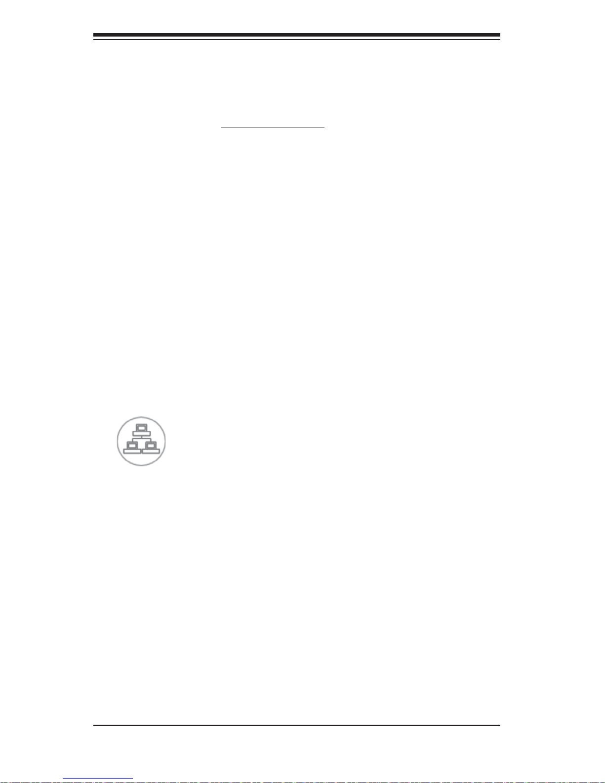
NIC
Indicates network activity on any of the LAN ports when fl ashing
 Loading...