

Supero SUPERSERVER 1027R-WRF User Manual
SUPERSERVER
1027R-WRF
®
SUPER
USER'S MANUAL
Revision 1.0

The information in this User’s Manual has been carefully reviewed and is believed to be accurate.
The vendor assumes no responsibility for any inaccuracies that may be contained in this document,
makes no commitment to update or to keep current the information in this manual, or to notify any
person or organization of the updates. Please Note: For the most up-to-date version of this
manual, please see our web site at www.supermicro.com.
Super Micro Computer, Inc. ("Supermicro") reserves the right to make changes to the product
described in this manual at any time and without notice. This product, including software and
documentation, is the property of Supermicro and/or its licensors, and is supplied only under a
license. Any use or reproduction of this product is not allowed, except as expressly permitted by
the terms of said license.
IN NO EVENT WILL SUPERMICRO BE LIABLE FOR DIRECT, INDIRECT, SPECIAL, INCIDENTAL,
SPECULATIVE OR CONSEQUENTIAL DAMAGES ARISING FROM THE USE OR INABILITY TO
USE THIS PRODUCT OR DOCUMENTATION, EVEN IF ADVISED OF THE POSSIBILITY OF
SUCH DAMAGES. IN PARTICULAR, SUPERMICRO SHALL NOT HAVE LIABILITY FOR ANY
HARDWARE, SOFTW ARE, OR DA TA STORED OR USED WITH THE PRODUCT, INCLUDING THE
COSTS OF REPAIRING, REPLACING, INTEGRATING, INSTALLING OR RECOVERING SUCH
HARDWARE, SOFTWARE, OR DATA.
Any disputes arising between manufacturer and customer shall be governed by the laws of Santa
Clara County in the State of California, USA. The State of California, County of Santa Clara shall
be the exclusive venue for the resolution of any such disputes. Super Micro's total liability for all
claims will not exceed the price paid for the hardware product.
FCC Statement: This equipment has been tested and found to comply with the limits for a Class
A digital device pursuant to Part 15 of the FCC Rules. These limits are designed to provide
reasonable protection against harmful interference when the equipment is operated in a commercial
environment. This equipment generates, uses, and can radiate radio frequency energy and, if not
installed and used in accordance with the manufacturer’s instruction manual, may cause harmful
interference with radio communications. Operation of this equipment in a residential area is likely
to cause harmful interference, in which case you will be required to correct the interference at your
own expense.
California Best Management Practices Regulations for Perchlorate Materials: This Perchlorate
warning applies only to products containing CR (Manganese Dioxide) Lithium coin cells. “Perchlorate
Material-special handling may apply. See www.dtsc.ca.gov/hazardouswaste/perchlorate”
WARNING: Handling of lead solder materials used in this
product may expose you to lead, a chemical known to
the State of California to cause birth defects and other
reproductive harm.
Manual Revision 1.0
Release Date: August 31, 2012
Unless you request and receive written permission from Super Micro Computer, Inc., you may not
copy any part of this document.
Information in this document is subject to change without notice. Other products and companies
referred to herein are trademarks or registered trademarks of their respective companies or mark
holders.
Copyright © 2012 by Super Micro Computer, Inc.
All rights reserved.
Printed in the United States of America

iii
Preface
Preface
About This Manual
This manual is written for professional system integrators and PC technicians. It
provides information for the installation and use of the SuperServer 1027R-WRF
Installation and maintainance should be performed by experienced technicians only .
The SuperServer 1027R-WRF is a high-end server based on the SC1 13TQ-R700WB
1U rackmount chassis and the X9DRW-iF dual processor serverboard.
Manual Organization
Chapter 1: Introduction
The fi rst chapter provides a checklist of the main components included with the
server system and describes the main features of the X9DRW-iF serverboard and
the SC113TQ-R700WB chassis.
Chapter 2: Server Installation
This chapter describes the steps necessary to install the SuperServer 1027R-WRF
into a rack and check out the server confi guration prior to powering up the system.
If your server was ordered without processor and memory components, this chapter
will refer you to the appropriate sections of the manual for their installation.
Chapter 3: System Interface
Refer here for details on the system interface, which includes the functions and
information provided by the control panel on the chassis as well as other LEDs
located throughout the system.
Chapter 4: System Safety
You should thoroughly familiarize yourself with this chapter for a general overview
of safety precautions that should be followed when installing and servicing the
SuperServer 1027R-WRF.
Chapter 5: Advanced Serverboard Setup
Chapter 5 provides detailed information on the X9DRW-iF serverboard, including the
locations and functions of connections, headers and jumpers. Refer to this chapter
when adding or removing processors or main memory and when reconfi guring the
serverboard.

SUPERSERVER 1027R-WRF USER'S MANUAL
iv
Chapter 6: Advanced Chassis Setup
Refer to Chapter 6 for detailed information on the SC113TQ-R700WB server
chassis. You should follow the procedures given in this chapter when installing,
removing or reconfi guring SAS/SATA or peripheral drives and when replacing
system power supply units and cooling fans.
Chapter 7: BIOS
The BIOS chapter includes an introduction to BIOS and provides detailed information
on running the CMOS Setup Utility for the X9DRW-iF serverboard.
Appendix A: BIOS Error Beep Codes
Appendix B: Installing Windows
Appendix C: System Specifi cations

Notes
Preface
v

vi
Table of Contents
Chapter 1 Introduction
1-1 Overview .........................................................................................................1-1
1-2 Serverboard Features .....................................................................................1-2
Processors ......................................................................................................1-2
Memory ...........................................................................................................1-2
Serial ATA ....................................................................................................... 1-2
Onboard Controllers/Ports ..............................................................................1-2
Graphics Controller .........................................................................................1-3
Other Features ................................................................................................ 1-3
1-3 Server Chassis Features ................................................................................1-3
System Power ................................................................................................. 1-3
Hard Drive Subsystem .................................................................................... 1-3
PCI Expansion Slots ....................................................................................... 1-3
Front Control Panel ......................................................................................... 1-3
I/O Backplane ..................................................................................................1-4
Cooling System ............................................................................................... 1-4
1-4 Advanced Power Management ....................................................................... 1-4
Intel® Intelligent Power Node Manager (NM) .................................................1-4
Manageability Engine (ME) ............................................................................. 1-4
1-5 Contacting Supermicro ....................................................................................1-6
Chapter 2Server Installation
2-1 Overview .........................................................................................................2-1
2-2 Unpacking the System .................................................................................... 2-1
2-3 Preparing for Setup ......................................................................................... 2-1
Choosing a Setup Location .............................................................................2-2
2-4 Precautions! ....................................................................................................2-2
Rack Precautions ............................................................................................ 2-2
Server Precautions ..........................................................................................2-2
Rack Mounting Considerations ....................................................................... 2-3
Ambient Operating Temperature ................................................................ 2-3
Reduced Airfl ow ......................................................................................... 2-3
Mechanical Loading ................................................................................... 2-3
Circuit Overloading ..................................................................................... 2-3
Reliable Ground ......................................................................................... 2-3
2-5 Installing the System into a Rack ................................................................... 2-4
Identifying the Sections of the Rack Rails ...................................................... 2-4
SUPERSERVER 1027R-WRF USER'S MANUAL

vii
Inner Rails .......................................................................................................2-5
Outer Rails ...................................................................................................... 2-6
Installing the Server into a Telco Rack ........................................................... 2-9
2-6 Checking the Serverboard Setup ..................................................................2-10
2-7 Checking the Drive Bay Setup .......................................................................2-11
Chapter 3 System Interface
3-1 Overview .........................................................................................................3-1
3-2 Control Panel Buttons ..................................................................................... 3-1
Reset ...............................................................................................................3-1
Power ..............................................................................................................3-1
UID ..................................................................................................................3-1
3-3 Control Panel LEDs ........................................................................................3-2
Universal Information LED .............................................................................. 3-2
NIC2 ................................................................................................................3-3
NIC1 ................................................................................................................3-3
HDD ................................................................................................................. 3-3
Power ..............................................................................................................3-3
3-4 Hard Drive Carrier LEDs ................................................................................. 3-4
3-5 Power Supply LEDs ........................................................................................ 3-4
700W Power Supply LED ............................................................................... 3-4
Chapter 4 System Safety
4-1 Electrical Safety Precautions .......................................................................... 4-1
4-2 General Safety Precautions ............................................................................ 4-2
4-3 ESD Precautions ............................................................................................. 4-3
4-4 Operating Precautions .................................................................................... 4-4
Chapter 5 Advanced Serverboard Setup
5-1 Handling the Serverboard ............................................................................... 5-1
Precautions .....................................................................................................5-1
Unpacking .......................................................................................................5-1
5-2 Processor and Heatsink Installation................................................................5-2
Installing a Passive CPU Heatsink ................................................................. 5-6
Removing the Heatsink ................................................................................... 5-7
5-3 Connecting Cables .......................................................................................... 5-8
Connecting Data Cables ................................................................................. 5-8
Connecting Power Cables ..............................................................................5-8
Connecting the Control Panel ......................................................................... 5-8
5-4 I/O Ports ..........................................................................................................5-9
Table of Contents

viii
5-5 Installing Memory .......................................................................................... 5-10
Memory Support ............................................................................................5-10
5-6 Adding PCI Expansion Cards ....................................................................... 5-13
5-7 Serverboard Details ...................................................................................... 5-14
X9DRW-iF Quick Reference ......................................................................... 5-15
5-8 Connector Defi nitions ................................................................................... 5-17
5-9 Jumper Settings ............................................................................................5-26
Explanation of Jumpers ................................................................................5-26
5-10 Onboard Indicators ........................................................................................5-28
5-11 SATA Drive Connections ............................................................................... 5-29
5-13 Installing Drivers ............................................................................................5-30
Supero Doctor III ........................................................................................... 5-31
Chapter 6 Advanced Chassis Setup
6-1 Static-Sensitive Devices ..................................................................................6-1
Precautions .....................................................................................................6-1
6-2 Control Panel ..................................................................................................6-2
6-3 System Fans ...................................................................................................6-2
System Fan Failure ......................................................................................... 6-3
6-4 Drive Bay Installation/Removal ....................................................................... 6-4
Accessing the Drive Bays ............................................................................... 6-4
Hard Drive Installation .....................................................................................6-4
DVD Drive Installation ..................................................................................... 6-7
6-5 Power Supply .................................................................................................. 6-8
Power Supply Failure ...................................................................................... 6-8
Chapter 7 BIOS
7-1 Introduction ......................................................................................................7-1
Starting the Setup Utility ................................................................................. 7-1
7-2 Main Menu ...................................................................................................... 7-1
System Time/System Date .............................................................................7-2
7-3 Advanced Settings Menu ................................................................................ 7-2
7-3 Event Logs .................................................................................................... 7-22
7-4 IPMI ...............................................................................................................7-24
7-5 Boot ...............................................................................................................7-26
7-6 Security .........................................................................................................7-27
7-7 Save & Exit ................................................................................................... 7-27
Appendix A BIOS Error Beep Codes
Appendix B System Specifi cations
SUPERSERVER 1027R-WRF USER'S MANUAL

Chapter 1
Introduction
1-1 Overview
Supermicro's SUPERSERVER 1027R-WRF is a dual processor, 1U rackmount
server. The 1027R-WRF is a high-end server comprised of two main subsystems:
the SC113TQ-R700WB 1U server chassis and the X9DRW-iF dual processor
serverboard. Please refer to our web site for information on operating systems that
have been certifi ed for use with the system (www.supermicro.com).
In addition to the serverboard and chassis, various hardware components have
been included with the 1027R-WRF, as listed below:
• Two (2) 1U passive CPU heat sink (SNK-P0047PS)
• One (1) SC815/113/116 Intel DP X9, X8 PC air shroud (MCP-310-19002-0N)
• Five (5) 40x56mm 4-pin PWM fans (FAN-0086L4)
• One (1) 70-cm front control cable 20-pin-to-20-pin w/tube (CBL-0335L)
• SAS/SATA Accessories
One (1) HD Backplane (BPN-SAS-113TQ-O-P)
One (1) 30 AWG 70/60/50/50-cm, W/70-cm SB AOC connection cable
(CBL-0288L-01)
One (1) 30 AWG Ipass to 4SATA 90/90/70/70-cm W/70-cm SB AOC
connection cable (CBL-0388L-01)
Eight (8) 2.5" hot-swap hard disk drive trays (MCP-220-00047-0B)
• One (1) set outer rail for 1U chassis (MCP-290-00101-0N)
• One (1) set inner rail, front for 1U chassis (MCP-290-00107-0N)
• One (1) set inner rail, extension for 1U chassis (MCP-290-00111-0N)
• One (1) riser card (RSC-R1UW-2E16-O-P)
• One CD containing drivers and utilities
Chapter 1: Introduction
1-1

1-2
SUPERSERVER 1027R-WRF USER'S MANUAL
1-2 Serverboard Features
At the heart of the SUPERSERVER 1027R-WRF lies the X9DRW-iF, a dual
processor serverboard based on the C602 chipset. Below are the main features of
the X9DRW-iF. (See Figure 1-1 for a block diagram of the chipset).
Processors
The X9DRW-iF supports single or dual E5-2600 series processors in
Socket R LGA 2011 type sockets. Please refer to our web site for a complete
listing of supported processors (www.supermicro.com).
Memory
The X9DRW-iF has sixteen (16) single/dual/tri/quad channel 240-pin DIMM sockets
that can support up to 512 GB of DDR3 1600/1333/1066/800 MHz speed registered
ECC RDIMM/LRDIMM SDRAM in two-channel memory bus. Memory sizes of
512 MB, 1 GB, 2 GB, 4 GB, 8 GB, 16 GB or 32 GB size @ 1.35V/1.5V voltages
are supported. Please refer to Chapter 5 for installing memory.
Note: LRDIMM (Reduced Load) memory supports only 1333/1066/800 MHz speed
memory.
Serial ATA
An on -chi p (Intel PCH C602) SATA c ontrol ler is integr ated into the X9 DRW-i F to
provid e a s i x-port SATA sub sy ste m (two SATA 3.0 and four SATA 2.0 ports), which
is R AID 0, 1, 5 and 10 (W ind ows SATA) or RA ID 0, 1 an d 10 (LINUX ) supp or te d.
By default t hes e SATA por ts a re no t use d in th is se r ver, but you c an add o pti ona l
cable s to co nnect t o these p or ts The S ATA dr ives ar e hot-s wappab le units .
Note: You must have RAID set up to enable the hot-swap capability of the SATA
drives. D ocum entati on on R AI D setup gui deline s can be fo und on our we b site.
Onboard Controllers/Ports
The color-coded I/O ports on the X9DRW-iF include two COM ports (one header
and one port), a VGA (monitor) port, six USB 2.0 ports (4x rear, 1x header for two
front panel), two gigabit Ethernet ports and one dedicated IPMI LAN port.
Note: For more information on IPMI confi guration, please refer to the IPMI User's
Guide posted on our website at http://www.supermicro.com/support/manuals/

Chapter 1: Introduction
1-3
Graphics Controller
The X9DRW-iF features an integrated Renesas Base-board Controller (BMC) chip,
which also acts as a video controller.
Other Features
Other onboard features that promote system health include onboard voltage
monitors, auto-switching voltage regulators, chassis and CPU overheat sensors,
power management, AC power loss recovery, virus protection and BIOS rescue.
1-3 Server Chassis Features
The SC113TQ-R700WB is Supermicro's third-generation 1U chassis and features
eight 2.5" hard drive bays and two high-effi ciency power supplies. The following is
a general outline of the main features of the SC113TQ-R700WB chassis.
System Power
When confi gured as a SuperServer 1027R-WRF, the SC113TQ-R700WB chassis
includes two redundant 700 Watt power supplies.
Hard Drive Subsystem
The SC113TQ-R700WB chassis was designed to support eight hot-swap SATA
hard drives.
PCI Expansion Slots
A riser card (RSC-R1UW-2E16-O-P) on the left side of the chassis can support two
PCI-E x16 cards. See section 5-6 for further details.)
Front Control Panel
The SC113TQ-R700WB control panel provides important system monitoring and
control information. LEDs indicate power on, network activity , hard disk drive activity
and a UID (Universal Information) LED. Also present are a main power button, a
system reset button and a UID button.

1-4
SUPERSERVER 1027R-WRF USER'S MANUAL
I/O Backplane
The SC113TQ-R700WB is an extended ATX form factor chassis that is designed to
be used in a 1U rackmount confi guration. Ports on the I/O backplane include one
COM port, a VGA port, four USB 2.0 ports, two one-gigabit Ethernet ports and a
dedicated IPMI LAN port. A UID (Unit Identifi er) button and LED are also located
beside the VGA port.
Cooling System
The SuperServer 1027R-WRF has an innovative cooling design that features fi ve
sets of 4-cm counter-rotating fans located in the middle section of the chassis.
There is a "Fan Speed Control Mode" setting in IPMI that allows chassis fan speed
to be determined by system temperature. The power supply module also includes
a cooling fan.
1-4 Advanced Power Management
Intel® Intelligent Power Node Manager (NM)
The Intel® Intelligent Power Node Manager (IPNM) provides your system with
real-time thermal control and power management for maximum energy effi ciency.
Although IPNM Specifi cation Version 1.5 is supported by the BMC (Baseboard
Management Controller), your system must also have IPNM-compatible
Manageability Engine (ME) fi rmware installed to use this feature.
Manageability Engine (ME)
The Manageability Engine, which is an ARC controller embedded in the IOH (I/O
Hub), provides Server Platform Services (SPS) to your system. The services
provided by SPS are different from those proveded by the ME on client platforms.
Chapter 1: Introduction
1-5
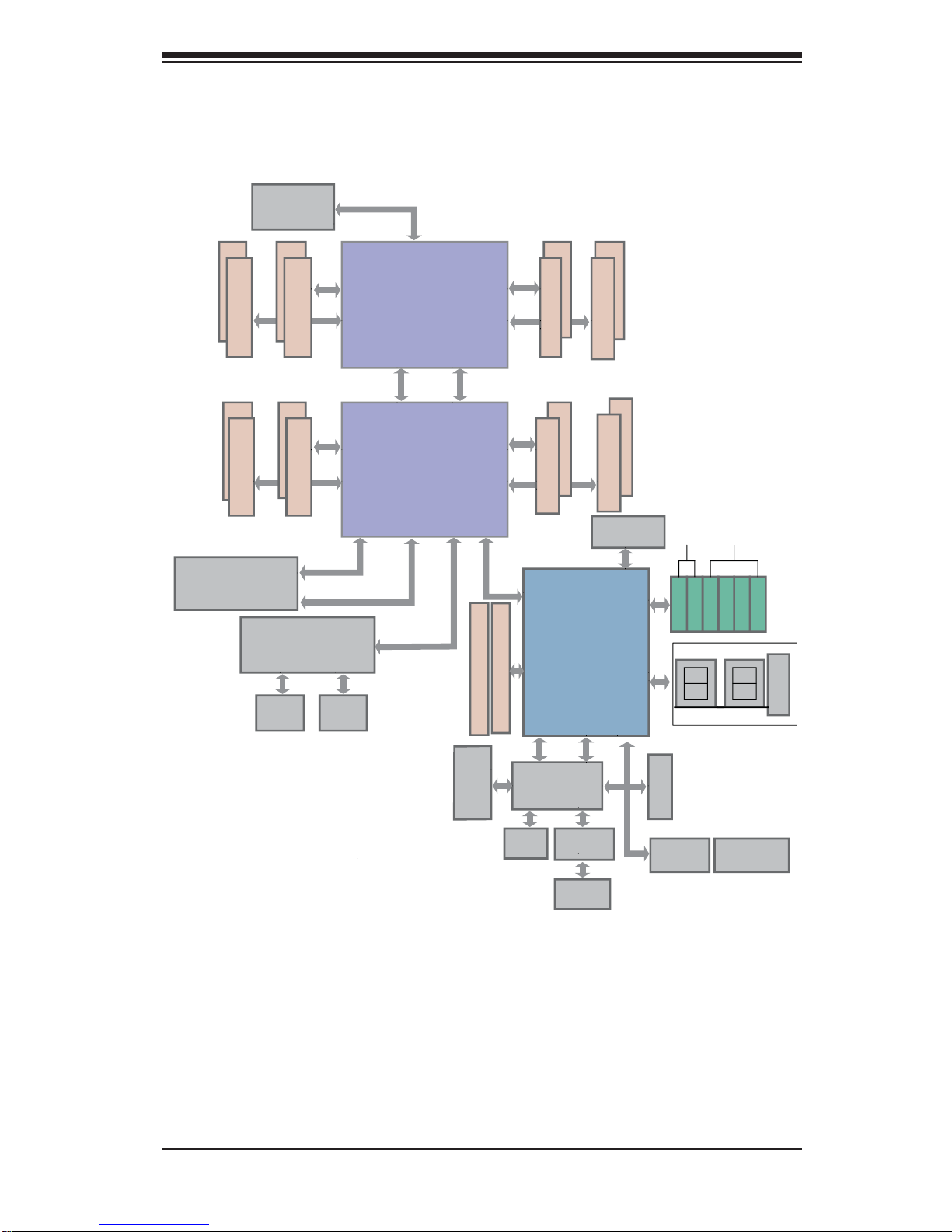
Figure 1-1. C602 Chipset:
System Block Diagram
Note: This is a general block diagram. Please see Chapter 5 for details.
PROCESSOR
PROCESSOR
DDR3 DIMM
#1
#2
DDR3 DIMM
DDR3 DIMM
DDR3 DIMM
DDR3 DIMM
#2
#1
DDR3 DIMM
G
A
CPU Rear
DDR3 DIMM
B
DDR3 DIMM
D
C
H
F
E
Socket 00
Socket 01
#1
#2
#1
#2
#1
#2
#1
#2
#1
#2
#1
#2
P0
P0
P1
P1
x1
x16
x16
x16
J1
Right Slot
PCIE 3.0x16
DMI
PE3 PE2 PE1
QPI
QPI
CPU Front
DMI
PE1PE2PE3
P0PE3
J3
Left Slot
PCIE 3.0x16+x16
x4 (Lane4~7)
UL1
I350AM2
JLAN1
RJ45
JLAN2
RJ45
Lane Reversal & Polarity Inversion
DMI: Lane Reversal
BIOS
SPI Flash
SPI
DMI
PEG [0...3]
PET8 USB [10,11] LPC
SSB
PCH C602
Gen 3 [1...7]
SATA [0...5]
USB [0...9]
SATA Gen3
SATA Gen2
SATA0
SATA1
SATA2
SATA3
SATA4
SATA5
DDR3 RAM
Renesas
VGA
BMC
TPM Chip
Super I/O
W83527
NCT7904D
HW Monitor
VGA
CONN
PHY
RTL8211E
IPMI LAN
RJ45
REAR
HDR 2X5
REAR
3Gbps
6Gbps
JSM2(SCU4~7)
(3F only)
JSM1(SCU0~3)

1-6
SUPERSERVER 1027R-WRF USER'S MANUAL
1-5 Contacting Supermicro
Headquarters
Address: Super Micro Computer, Inc.
980 Rock Ave.
San Jose, CA 95131 U.S.A.
Tel: +1 (408) 503-8000
Fax: +1 (408) 503-8008
Email: marketing@supermicro.com (General Information)
support@supermicro.com (Technical Support)
Web Site: www.supermicro.com
Europe
Address: Super Micro Computer B.V.
Het Sterrenbeeld 28, 5215 ML
's-Hertogenbosch, The Netherlands
Tel: +31 (0) 73-6400390
Fax: +31 (0) 73-6416525
Email: sales@supermicro.nl (General Information)
support@supermicro.nl (Technical Support)
rma@supermicro.nl (Customer Support)
Asia-Pacifi c
Address: Super Micro Computer, Inc.
4F, No. 232-1, Liancheng Rd.
Chung-Ho Dist., New Taipei City 235
Taiwan, R.O.C.
Tel: +886-(2) 8226-3990
Fax: +886-(2) 8226-3991
Web Site: www.supermicro.com.tw
Technical Support:
Email: support@supermicro.com.tw
Tel: +886-(2) 8226-5990
Chapter 2: Server Installation
2-1
Chapter 2
Server Installation
2-1 Overview
This chapter provides a quick setup checklist to get your SuperServer 1027R-WRF
up and running. Following these steps in the order given should enable you to have
the system operational within a minimum amount of time. This quick setup assumes
that your system has come to you with the processors and memory preinstalled. If
your system is not already fully integrated with a serverboard, processors, system
memory etc., please turn to the chapter or section noted in each step for details on
installing specifi c components.
2-2 Unpacking the System
You should inspect the box the SuperServer 1027R-WRF was shipped in and note
if it was damaged in any way. If the server itself shows damage you should fi le a
damage claim with the carrier who delivered it.
Decide on a suitable location for the rack unit that will hold the SuperServer
1027R-WRF. It should be situated in a clean, dust-free area that is well ventilated.
Avoid areas where heat, electrical noise and electromagnetic fi elds are generated.
You will also need it placed near a grounded power outlet. Be sure to read the Rack
and Server Precautions in the next section.
2-3 Preparing for Setup
The box the SuperServer 1027R-WRF was shipped in should include two sets of
rail assemblies, two rail mounting brackets and the mounting screws you will need
to install the system into the rack. Follow the steps in the order given to complete
the installation process in a minimum amount of time. Please read this section in
its entirety before you begin the installation procedure outlined in the sections that
follow.

2-2
SUPERSERVER 1027R-WRF USER'S MANUAL
Choosing a Setup Location
• Leave enough clearance in front of the rack to enable you to open the front door
completely (~25 inches) and approximately 30 inches of clearance in the back
of the rack to allow for suffi cient airfl ow and ease in servicing.This product is for
installation only in a Restricted Access Location (dedicated equipment rooms,
service closets and the like).
• This product is not suitable for use with visual display work place devices
acccording to §2 of the the German Ordinance for Work with Visual Display Units.
2-4 Precautions!
Rack Precautions
• Ensure that the leveling jacks on the bottom of the rack are fully extended to
the fl oor with the full weight of the rack resting on them.
• In single rack installation, stabilizers should be attached to the rack. In multiple
rack installations, the racks should be coupled together.
• Always make sure the rack is stable before extending a component from the
rack.
• You should extend only one component at a time - extending two or more
simultaneously may cause the rack to become unstable.
Server Precautions
• Review the electrical and general safety precautions in Chapter 4.
• Determine the placement of each component in the rack before you install the
rails.
• Install the heaviest server components on the bottom of the rack fi rst, and then
work up.
• Use a regulating uninterruptible power supply (UPS) to protect the server from
power surges, voltage spikes and to keep your system operating in case of a
power failure.
• Allow the hot plug SATA drives and power supply modules to cool before
touching them.
• Always keep the rack's front door and all panels and components on the servers
closed when not servicing to maintain proper cooling.

Chapter 2: Server Installation
2-3
Rack Mounting Considerations
Ambient Operating Temperature
If installed in a closed or multi-unit rack assembly, the ambient operating
temperature of the rack environment may be greater than the ambient temperature
of the room. Therefore, consideration should be given to installing the equipment
in an environment compatible with the manufacturer’s maximum rated ambient
temperature (Tmra).
Reduced Airfl ow
Equipment should be mounted into a rack so that the amount of airfl ow required
for safe operation is not compromised.
Mechanical Loading
Equipment should be mounted into a rack so that a hazardous condition does not
arise due to uneven mechanical loading.
Circuit Overloading
Consideration should be given to the connection of the equipment to the power
supply circuitry and the effect that any possible overloading of circuits might have
on overcurrent protection and power supply wiring. Appropriate consideration of
equipment nameplate ratings should be used when addressing this concern.
Reliable Ground
A reliable ground must be maintained at all times. To ensure this, the rack
itself should be grounded. Particular attention should be given to power supply
connections other than the direct connections to the branch circuit (i.e. the use of
power strips, etc.).
2-4
SUPERSERVER 1027R-WRF USER'S MANUAL
2-5 Installing the System into a Rack
This section provides information on installing the SuperServer 1027R-WRF into a
rack. If the SuperServer 1027R-WRF has already been mounted into a rack, you
can skip ahead to Sections 2-5 and 2-6.
Note: This rail will fi t a rack between 26" and 33.5" deep.
There are a variety of rack units on the market, which may mean the assembly
procedure will differ slightly . The following is a guideline for installing the SuperServer
1027R-WRF into a rack with the rack rails provided. You should also refer to the
installation instructions that came with the rack unit you are using.
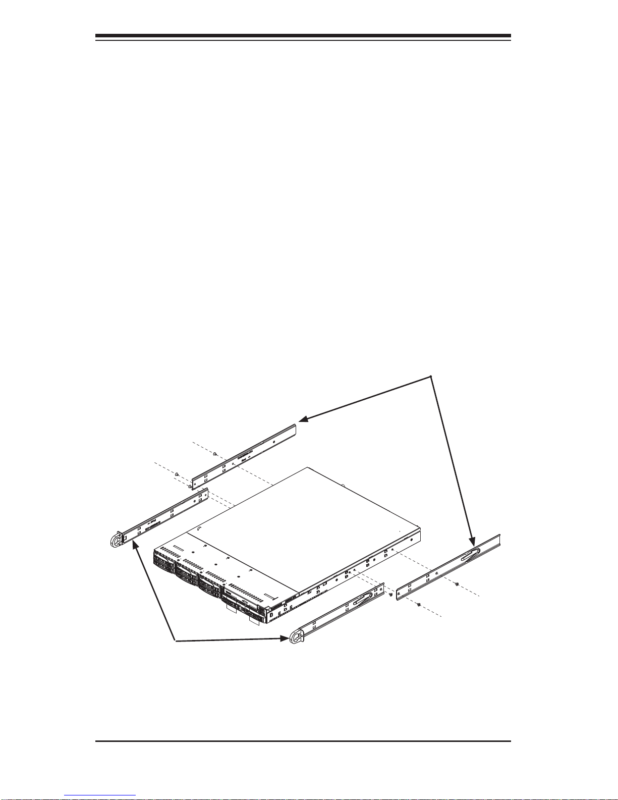
Identifying the Sections of the Rack Rails
Each assembly consists of two sections: an inner fi xed chassis rail that secures
directly to the server chassis and an outer fi xed rack rail that secures directly to
the rack itself.
Figure 2-1. Identifying the Sections of the Rack Rails
Inner Rails
Inner Rail
Extensions
Chapter 2: Server Installation
2-5
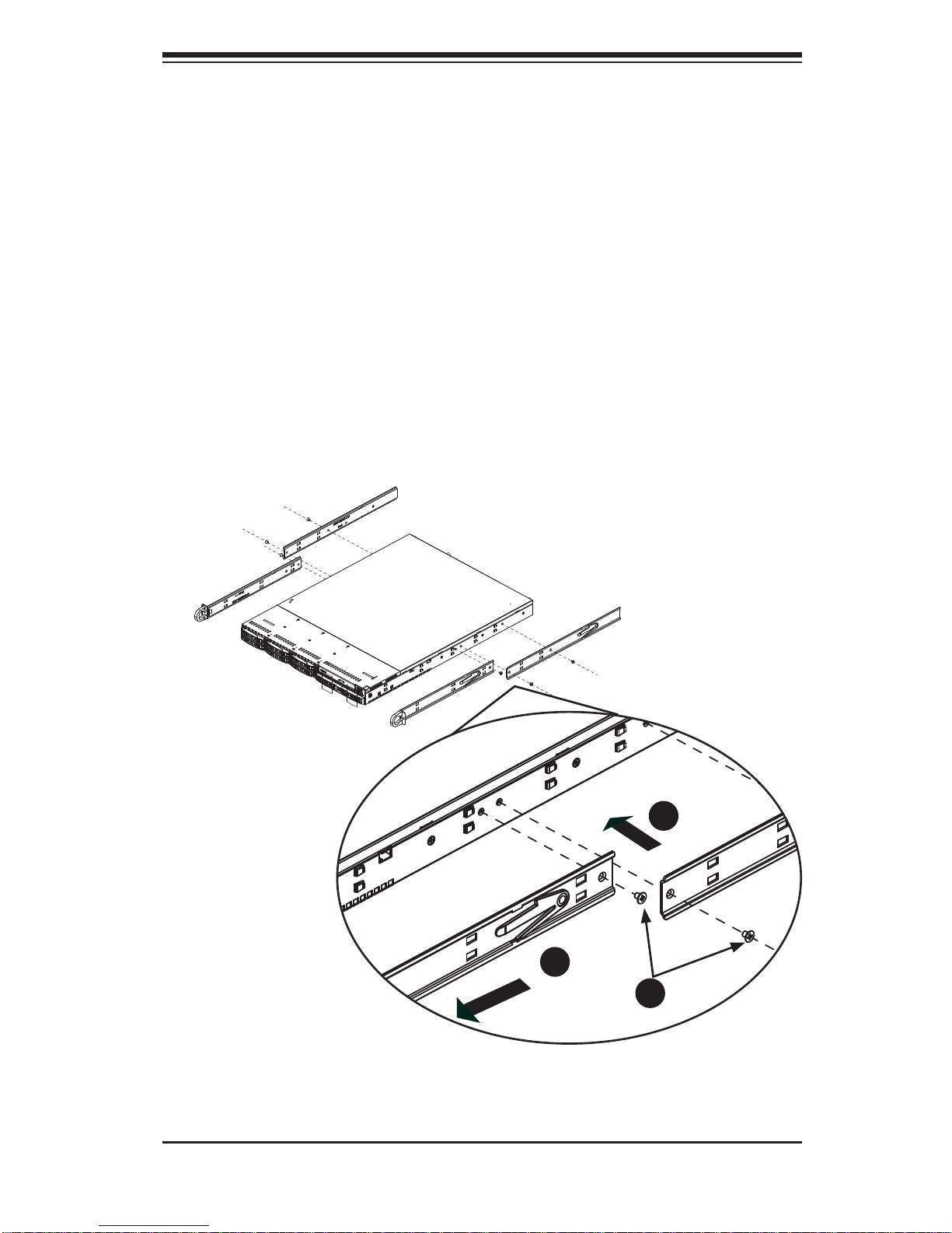
Figure 2-2. Installing Chassis Rails
Inner Rails
The SC1 13 chassis includes a set of inner rails in two sections: inner rails and inner
rail extensions. The inner rails are pre-attached and do not interfere with normal use
of the chassis if you decide not to use a server rack. Attach the inner rail extension
to stabilize the chassis within the rack.
Installing the Inner Rails (Figure 2-2)
1. Place the inner rack extensions on the side of the chassis aligning the hooks
of the chassis with the rail extension holes. Make sure the extension faces
"outward" just like the pre-attached inner rail.
2. Slide the extension toward the front of the chassis.
3. Secure the chassis with two screws as illustrated.
4. Repeat steps 1-3 for the other inner rail extension.
1
1
1
2
1
3
2-6
SUPERSERVER 1027R-WRF USER'S MANUAL
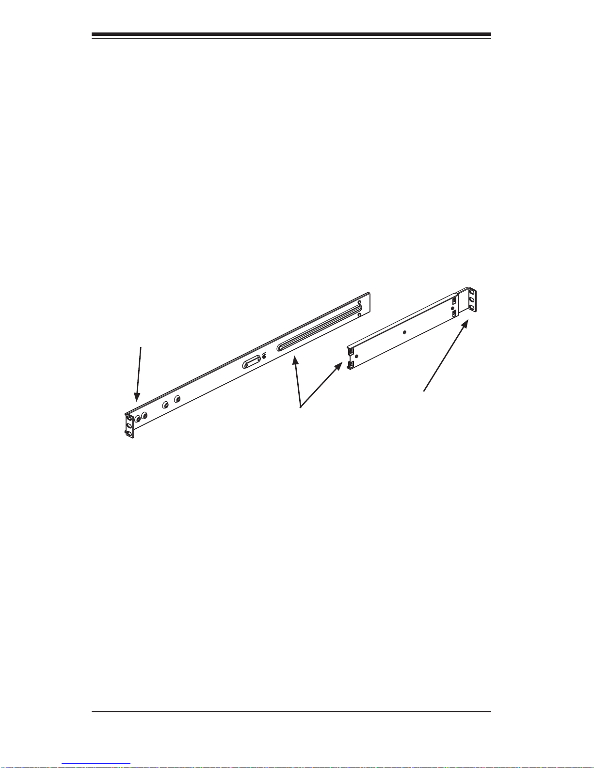
Outer Rails
Installing the Outer Rails to the Rack (Figures 2-3 and 2-4)
1. Attach the short bracket to the outside of the long bracket. You must align the
pins with the slides. Also, both bracket ends must face the same direction.
2. Adjust both the short and long brackets to the proper distance so that the rail
fi ts snugly into the rack.
3. Secure the long bracket to the front side of the outer rail with two M5 screws
and the short bracket to the rear side of the outer rail with three M5 screws.
4. Repeat steps 1-4 for the left outer rail.
Figure 2-3. Assembling the Outer Rails
Secure to the
Front of the Rack
Secure to the
Rear of the Rack
Attach Outer Rails
Together
Chapter 2: Server Installation
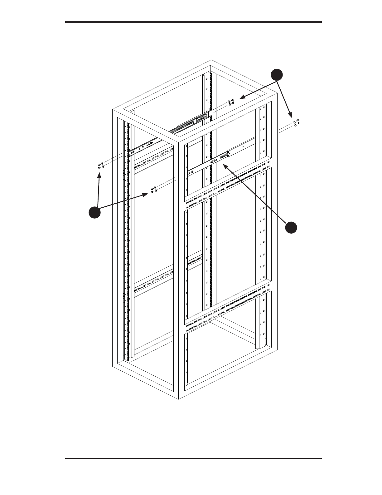
2-7
Figure 2-4. Installing the Outer Rails to the Rack
1
2
1
3
1
3
2-8
SUPERSERVER 1027R-WRF USER'S MANUAL
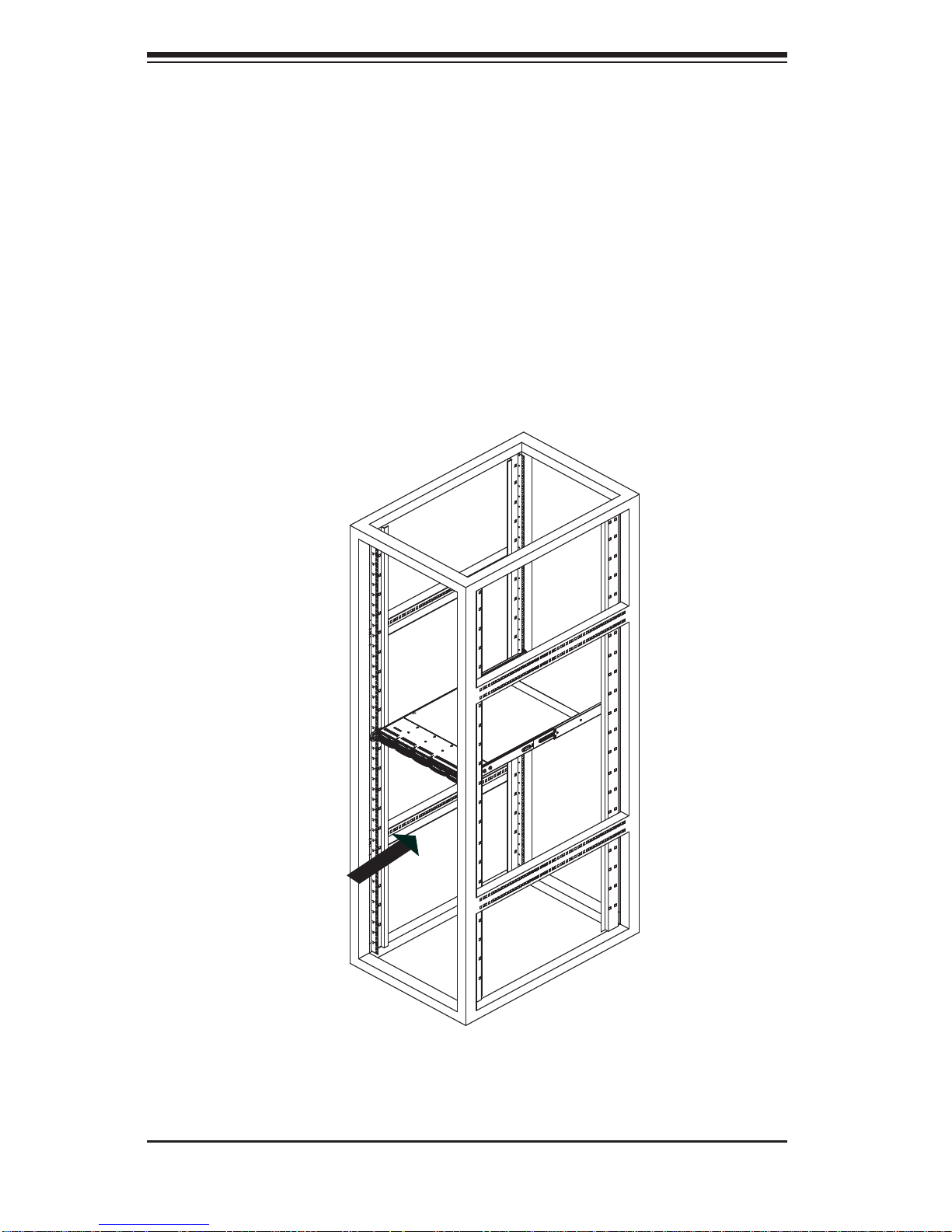
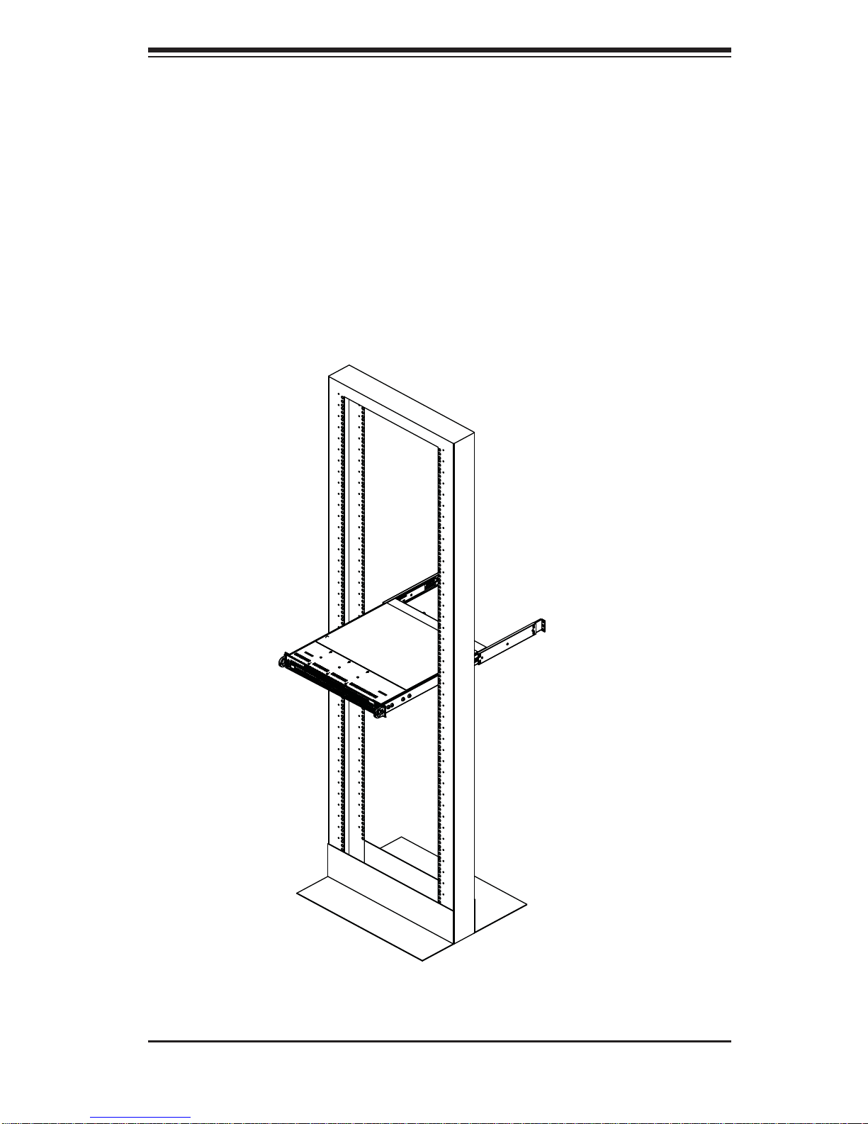
Figure 2-5. Installing the Server into a Rack
Installing the Chassis into a Rack (Figure 2-5)
1. Confi rm that chassis includes the inner rails and rail extensions . Also, confi rm
that the outer rails are installed on the rack.
2. Line chassis rails with the front of the rack rails.
3. Slide the chassis rails into the rack rails, keeping the pressure even on both
sides (you may have to depress the locking tabs when inserting). When the
server has been pushed completely into the rack, you should hear the locking
tabs "click".
4. (Optional) Insert and tightening the thumbscrews that hold the front of the
server to the rack.
Chapter 2: Server Installation
2-9
Installing the Server into a Telco Rack
To install the SuperServer SuperServer 1027R-WRF into a Telco type rack, use two
L-shaped brackets on either side of the chassis (four total). First, determine how
far follow the server will extend out the front of the rack. Larger chassis should be
positioned to balance the weight between front and back. If a bezel is included on
your server, remove it. Then attach the two front brackets to each side of the chassis,
then the two rear brackets positioned with just enough space to accommodate the
width of the telco rack. Finish by sliding the chassis into the rack and tightening
the brackets to the rack.
Figure 2-6. Installing the Server into a Telco Rack
2-10
SUPERSERVER 1027R-WRF USER'S MANUAL
2-6 Checking the Serverboard Setup
After you install the SuperServer 1027R-WRF in the rack, you will need to open
the unit to make sure the serverboard is properly installed and all the connections
have been made.
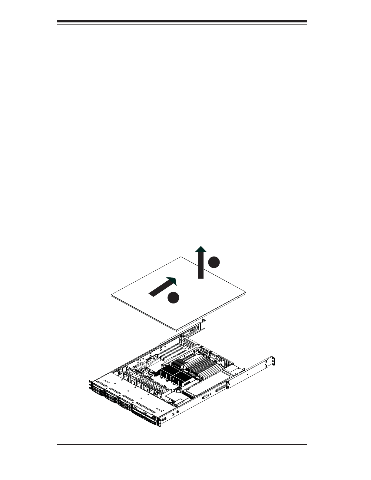
Removing the Chassis Cover (Figure 2-5)
1. Grasp the two handles on either side and pull the unit straight out until it
locks (you will hear a "click").
2. Remove the screws securing the top cover to the chssis.
3. Slide the cover toward the rear of the chassis.
4. Lift the cover off the chassis.
Checking the Components
1. You should have one or two processors already installed into the serverboard.
Each processor needs its own heatsink. See Chapter 5 for instructions on
processor and heatsink installation.
Figure 2-5: Removing the Chassis Cover
1
3
1
2

Chapter 2: Server Installation
2-11
2. Your SuperServer 1027R-WRF system may have come with system memory
already installed. Make sure all DIMMs are fully seated in their slots. For
details on adding system memory, refer to Chapter 5.
3. If desired, you can install add-on cards to the system. See Chapter 5 for
details on installing PCI add-on cards.
4. Make sure all power and data cables are properly connected and not blocking
the chassis airfl ow. See Chapter 5 for details on cable connections. Also,
check the air seals for damage. The air seals are located under the blower
fan and beneath the frame cross section that separates the drive bay area
from the serverboard area of the chassis.
2-7 Checking the Drive Bay Setup
Next, you should check to make sure the hard drives have been properly installed
and all connections have been made.
Checking the Drives
1. For servicing the hard drives, you will need to remove the top chassis cover.
2. If you need to remove or install hard drives, please refer to Chapter 6.
Checking the Airfl ow
1. Airfl ow is provided by four 4-cm counter-rotating fans. The system component
layout was carefully designed to direct suffi cient cooling airfl ow to the
components that generate the most heat.
2. Note that all power and data cables have been routed in such a way that they
do not block the airfl ow generated by the fans.
Providing Power
1. The last thing you must do is to provide input power to the system. Plug the
power cord from the power supply unit into a high-quality power strip that
offers protection from electrical noise and power surges. It is recommended
that you use an uninterruptible power supply (UPS).
2. Finish by depressing the power button on the chassis control panel.

2-12
SUPERSERVER 1027R-WRF USER'S MANUAL
Notes
Chapter 3: System Interface
3-1
Chapter 3
System Interface
3-1 Overview
There are several LEDs on the control panel to keep you constantly informed of the
overall status of the system as well as the three buttons described below.
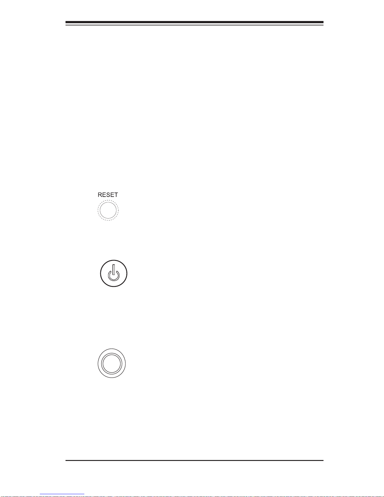
3-2 Control Panel Buttons
There are three buttons located on the front of the chassis: a reset button, a power
on/off button and a UID button.
Reset
Use the reset button to reboot the system.
Power
This is the main power button, which is used to apply or turn off the main system
power. T urning off system power with this button removes the main power but keeps
standby power supplied to the system.
UID
Depressing the UID (unit identifi er) button illuminates an LED on both the front
and rear of the chassis for easy system location in large stack confi gurations. The
LED will remain on until the button is pushed a second time. Another UID button
on the rear of the chassis serves the same function. See the table in Figure 3-1 for
descriptions of UID LED states.
3-2
SUPERSERVER 1027R-WRF USER'S MANUAL
3-3 Control Panel LEDs
The control panel located on the front of the SC113TQ-R700WB chassis has fi ve
LEDs. These LEDs provide you with critical information related to different parts of
the system. This section explains what each LED indicates when illuminated and
any corrective action you may need to take.
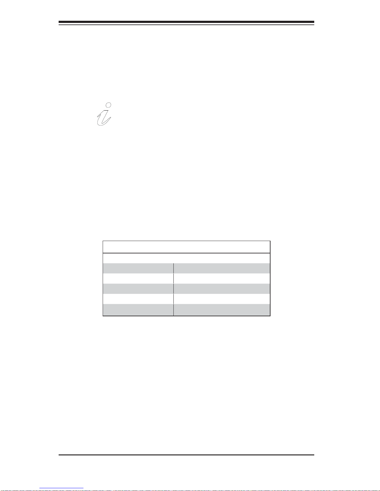
Universal Information LED
When this LED blinks red quickly, it indicates a fan failure and when blinking red
slowly a power failure. This LED will be blue when used for UID (Unit Identifi er).
When on continuously it indicates an overheat condition, which may be caused by
cables obstructing the airfl ow in the system or the ambient room temperature being
too warm. Check the routing of the cables and make sure all fans are present and
operating normally. You should also check to make sure that the chassis covers
are installed. Finally, verify that the heatsinks are installed properly (see Chapter
5). This LED will remain fl ashing or on as long as the indicated condition exists.
See the table below for descriptions of the LED states.
Universal Information LED States
State Indication
Fast Blinking Red (1x/sec) Fan Fail
Solid Red CPU Overheat
Slow Blinking Red (1x/4 sec) Power Fail
Solid Blue Local UID Button Depressed
Blinking Blue IPMI-Activated UID
Note: deactivating the UID LED must be performed in the same way it was activated.
(If the UID LED was activated via IPMI, you can only turn the LED off via IPMI and
not with the UID button.)
Chapter 3: System Interface
3-3
NIC2
Indicates network activity on LAN2 when fl ashing.
NIC1
Indicates network activity on LAN1 when fl ashing.
HDD
Indicates IDE channel activity when fl ashing.
Power
Indicates power is being supplied to the system's power supply units. This LED
should normally be illuminated when the system is operating.
3-4
SUPERSERVER 1027R-WRF USER'S MANUAL
3-4 Hard Drive Carrier LEDs
Each hard drive carrier has two LEDs.
• Green: When illuminated, the green LED on the front of the drive carrier
indicates drive activity. A connection to the SATA backplane enables this LED
to blink on and off when that particular drive is being accessed.
• Red: The red LED indicates two states. When blinking, it indicates the drive is
rebuilding. When solid, it indicates a drive failure. If a drive fails, you should be
notifi ed by your system management software. Please refer to Chapter 6 for
instructions on replacing failed drives.
3-5 Power Supply LEDs
This chassis provides several options which may include hot-swappable, coldswappable, and redundant power supplies. Some power supplies include an LED
in the rear with the following defi nitions:
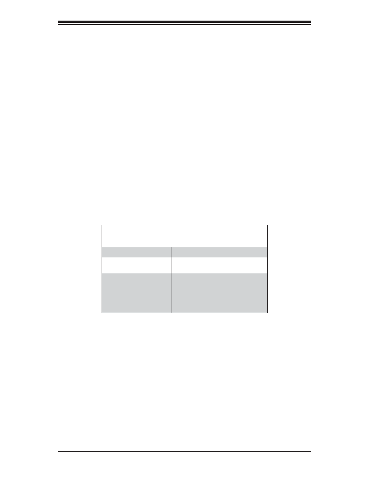
700W Power Supply LED
700W Power Supply LEDs
State Indication
Solid: Green System is on.
Solid: Amber System is off and plugged in or 5V stand
by on.
Blinking: Amber
(Only for 650W)
Power supply internal temperature has
reached 63º Celsius, and will be shut
down if the temperature reaches 70º
Celsius.
• Solid Green: When illuminated, the green LED indicates that the power supply
is on.
• Solid Amber: When illuminated, the amber LED indicates the power supply is
plugged in and turned off, or the system is off but in an abnormal state.
 Loading...