

Supero SuperServer 1027GR-72RT2+, SuperServer 1027GR-72R2+, SuperServer 1027GR-TRT2+, SuperServer 1027GR-TR2+ User Manual
SUPER
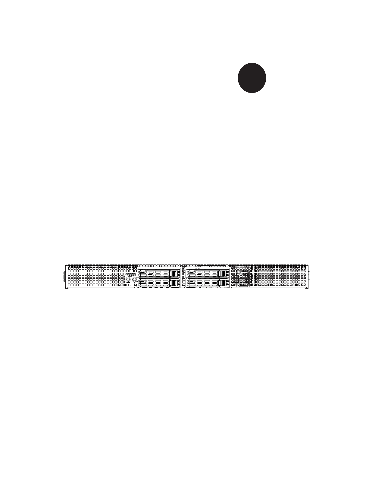
SUPERSERVER
1027GR-72RT2+
1027GR-72R2+
1027GR-TRT2+
1027GR-TR2+
®
USER’S MANUAL
Revision 1.0

The information in this User’s Manual has been carefully reviewed and is believed to be accurate.
The vendor assumes no responsibility for any inaccuracies that may be contained in this document,
makes no commitment to update or to keep current the information in this manual, or to notify any
person or organization of the updates. Please Note: For the most up-to-date version of this
manual, please see our web site at
www.supermicro.com.
Super Micro Computer, Inc. ("Supermicro") reserves the right to make changes to the product
described in this manual at any time and without notice. This product, including software and documentation, is the property of Supermicro and/or its licensors, and is supplied only under a license.
Any use or reproduction of this product is not allowed, except as expressly permitted by the terms
of said license.
IN NO EVENT WILL SUPERMICRO BE LIABLE FOR DIRECT, INDIRECT, SPECIAL, INCIDENTAL,
SPECULATIVE OR CONSEQUENTIAL DAMAGES ARISING FROM THE USE OR INABILITY TO
USE THIS PRODUCT OR DOCUMENTATION, EVEN IF ADVISED OF THE POSSIBILITY OF
SUCH DAMAGES. IN PARTICULAR, SUPERMICRO SHALL NOT HAVE LIABILITY FOR ANY
HARDWARE, SOFTW ARE, OR DA TA STORED OR USED WITH THE PRODUCT, INCLUDING THE
COSTS OF REPAIRING, REPLACING, INTEGRATING, INSTALLING OR RECOVERING SUCH
HARDWARE, SOFTWARE, OR DATA.
Any disputes arising between manufacturer and customer shall be governed by the laws of Santa
Clara County in the State of California, USA. The State of California, County of Santa Clara shall
be the exclusive venue for the resolution of any such disputes. Super Micro's total liability for all
claims will not exceed the price paid for the hardware product.
FCC Statement: This equipment has been tested and found to comply with the limits for a Class A
digital device pursuant to Part 15 of the FCC Rules. These limits are designed to provide reasonable
protection against harmful interference when the equipment is operated in a commercial environment. This equipment generates, uses, and can radiate radio frequency energy and, if not installed
and used in accordance with the manufacturer’s instruction manual, may cause harmful interference
with radio communications. Operation of this equipment in a residential area is likely to cause harmful
interference, in which case you will be required to correct the interference at your own expense.
California Best Management Practices Regulations for Perchlorate Materials: This Perchlorate warning applies only to products containing CR (Manganese Dioxide) Lithium coin cells. “Perchlorate
Material-special handling may apply. See
www.dtsc.ca.gov/hazardouswaste/perchlorate”
WARNING: Handling of lead solder materials used in this
product may expose you to lead, a chemical known to the
State of California to cause birth defects and other reproductive harm.
Manual Revision 1.0
Release Date: August 14, 2013
Unless you request and receive written permission from Super Micro Computer, Inc., you may not
copy any part of this document.
Information in this document is subject to change without notice. Other products and companies
referred to herein are trademarks or registered trademarks of their respective companies or mark
holders.
Copyright © 2013 by Super Micro Computer, Inc.
All rights reserved.
Printed in the United States of America

Preface
About This Manual
This manual is written for professional system integrators and PC technicians.
It provides information for the installation and use of the SuperServer 1027GR72RT2+/72R2+/TRT2+/TR2+. Installation and maintenance should be performed
by experienced technicians only.
The SuperServer 1027GR-72RT2+/72R2+/TRT2+/TR2+ is based on the SC118GH-R1K66B 1U server chassis and the Super X9DRG-HF+II/X9DRG-HFT+II
serverboard. Please refer to our web site for an up-to-date list of supported operating
systems, processors and memory. See Chapter 1 for a list of differences between
the server models.
Manual Organization
Chapter 1: Introduction
The fi rst chapter provides a checklist of the main components included with the
server system and describes the main features of the Super X9DRG-HF+II/X9DRGHFT+II serverboard and the SC118GH-R1K66B chassis.
Chapter 2: Server Installation
This chapter describes the steps necessary to install the system into a rack and
check out the server confi guration prior to powering up the system. If your server
was ordered without the processor and memory components, this chapter will refer
you to the appropriate sections of the manual for their installation.
Chapter 3: System Interface
Refer to this chapter for details on the system interface, which includes the functions
and information provided by the control panel on the chassis as well as other LEDs
located throughout the system.
Chapter 4: Standardized Safety Warnings
You should thoroughly familiarize yourself with this chapter for a general overview
of safety precautions that should be followed when installing and servicing the
system.
iii
Preface

SUPERSERVER 1027GR-72RT2+/72R2+/TRT2+/TR2+ User's Manual
iv
Chapter 5: Advanced Serverboard Setup
Chapter 5 provides detailed information on the X9DRG-HF+II/X9DRG-HFT+II
serverboard, including the locations and functions of connectors, headers and jumpers. Refer to this chapter when adding or removing processors or main memory
and when reconfi guring the serverboard.
Chapter 6: Advanced Chassis Setup
Refer to Chapter 6 for detailed information on the SC1 18GH-R1K66B 1U rackmount
server chassis. You should follow the procedures given in this chapter when installing, removing or reconfi guring SATA or peripheral drives and when replacing system
power supply units and cooling fans.
Chapter 7: BIOS
The BIOS chapter includes an introduction to BIOS and provides detailed information on running the CMOS Setup Utility.
Appendix A: BIOS Eror Beep Codes
Appendix B: System Specifi cations

v
Preface
Notes

vi
Table of Contents
Chapter 1 Introduction
1-1 Overview .........................................................................................................1-1
1-2 Serverboard Features .....................................................................................1-2
Processors ......................................................................................................1-2
Memory ...........................................................................................................1-2
Serial ATA .......................................................................................................1-2
PCI Expansion Slots ....................................................................................... 1-2
Onboard Controllers/Ports ..............................................................................1-2
IPMI .................................................................................................................1-2
1-3 Server Chassis Features ................................................................................1-3
System Power ................................................................................................. 1-3
SATA Subsystem .............................................................................................1-3
Front Control Panel .........................................................................................1-3
Cooling System ............................................................................................... 1-3
1-4 GPU Subsystem ..............................................................................................1-4
1-4 Contacting Supermicro .................................................................................... 1-6
Chapter 2 Server Installation
2-1 Overview .........................................................................................................2-1
2-2 Unpacking the System .................................................................................... 2-1
2-3 Preparing for Setup .........................................................................................2-1
Choosing a Setup Location .............................................................................2-1
2-4 Warnings and Precautions! ............................................................................. 2-2
Rack Precautions ............................................................................................ 2-2
Server Precautions ..........................................................................................2-2
Rack Mounting Considerations .......................................................................2-3
Ambient Operating Temperature ................................................................ 2-3
Reduced Airfl ow .........................................................................................2-3
Mechanical Loading ................................................................................... 2-3
Circuit Overloading .....................................................................................2-3
Reliable Ground ......................................................................................... 2-3
2-5 Installing the System into a Rack ................................................................... 2-4
Identifying the Sections of the Rack Rails ...................................................... 2-4
Installing the Inner Rail Extensions ................................................................2-5
Assembling the Outer Rails ............................................................................ 2-6
Installing the Outer Rails onto the Rack ......................................................... 2-7
Installing and Removing the Chassis From a Rack ....................................... 2-8
SUPERSERVER 1027GR-72RT2+/72R2+/TRT2+/TR2+ User's Manual

vii
Table of Contents
Installing the Server into a Telco Rack ........................................................... 2-9
Chapter 3 System Interface
3-1 Overview .........................................................................................................3-1
3-2 Control Panel Buttons ..................................................................................... 3-1
3-3 Control Panel LEDs ........................................................................................3-2
3-4 Drive Carrier LEDs ..........................................................................................3-3
Chapter 4 Standardized Warning Statements for AC Systems
4-1 About Standardized Warning Statements .......................................................4-1
Warning Defi nition ...........................................................................................4-1
Installation Instructions ....................................................................................4-4
Circuit Breaker ................................................................................................ 4-5
Power Disconnection Warning ........................................................................ 4-6
Equipment Installation ..................................................................................... 4-8
Restricted Area ................................................................................................ 4-9
Battery Handling ............................................................................................4-10
Redundant Power Supplies ..........................................................................4-12
Backplane Voltage ........................................................................................ 4-13
Comply with Local and National Electrical Codes ........................................ 4-14
Product Disposal ........................................................................................... 4-15
Hot Swap Fan Warning ................................................................................. 4-16
Power Cable and AC Adapter ...................................................................... 4-18
Chapter 5 Advanced Serverboard Setup
5-1 Handling the Serverboard ............................................................................... 5-1
Precautions .....................................................................................................5-1
Unpacking .......................................................................................................5-1
5-2 Connecting Cables .......................................................................................... 5-2
Connecting Data Cables ................................................................................. 5-2
Connecting Power Cables ..............................................................................5-2
Connecting the Control Panel ......................................................................... 5-2
5-3 I/O Ports ..........................................................................................................5-3
5-5 Installing the Processor and Heatsink ............................................................ 5-4
Installing an LGA 2011 Processor ................................................................... 5-4
Installing a CPU Heatsink ............................................................................... 5-7
Memory Support .............................................................................................. 5-8
Processor/DIMM Population Confi gurations ..............................................5-9
5-6 Expansion Cards ........................................................................................... 5-10
5-7 Serverboard Details .......................................................................................5-11
X9DRG-HF+II/ X9DRG-HTF+II Quick Reference ......................................... 5-12

viii
5-8 Connector Defi nitions ................................................................................... 5-14
5-9 Jumper Settings ............................................................................................5-20
5-10 Onboard Indicators ........................................................................................5-22
5-11 SATA Ports ....................................................................................................5-23
5-12 Installing Software ......................................................................................... 5-24
SuperDoctor III .............................................................................................. 5-25
5-13 Onboard Battery ............................................................................................ 5-27
Chapter 6 Advanced Chassis Setup
6-1 Static-Sensitive Devices ..................................................................................6-1
Precautions .....................................................................................................6-1
6-2 Control Panel ..................................................................................................6-2
6-3 System Cooling ............................................................................................... 6-2
System Fan Failure .........................................................................................6-3
Installing the Air Shroud .................................................................................. 6-4
Installing Graphics (GPU) Cards.....................................................................6-5
6-4 Drive Bay Installation/Removal .......................................................................6-6
Accessing the Drive Bays ...............................................................................6-6
Hard Drive Installation ..................................................................................... 6-6
6-5 Power Supply .................................................................................................. 6-9
Chapter 7 BIOS
7-1 Introduction ......................................................................................................7-1
Starting BIOS Setup Utility .............................................................................. 7-1
How To Change the Confi guration Data .........................................................7-2
Starting the Setup Utility ................................................................................. 7-2
7-2 Main Setup ...................................................................................................... 7-2
7-3 Advanced Setup Confi gurations......................................................................7-4
7-4 Event Logs .................................................................................................... 7-24
7-5 IPMI ............................................................................................................... 7-26
7-6 Boot ............................................................................................................... 7-28
7-7 Secur ity ......................................................................................................... 7-29
7-8 Save & Exit ................................................................................................... 7-31
Appendix A BIOS Error Beep Codes
Appendix B System Specifi cations
SUPERSERVER 1027GR-72RT2+/72R2+/TRT2+/TR2+ User's Manual

Chapter 1
Introduction
1-1 Overview
The SuperServer 1027GR-72RT2+/72R2+/TRT2+/TR2+ series is a GPU-optimized
server comprised of two main subsystems: the SC118GH-R1K66B 1U server chassis and the X9DRG-HF+II/X9DRG-HFT+II serverboard. Please refer to our web
site for information on operating systems that have been certifi ed for use with the
system (www.supermicro.com).
• Ten 4-cm counter-rotating fans (FAN-0141L4)
• One air shroud (MCP-310-11803-0N)
• Two passive CPU heatsinks (SNK-P0047PS:CPU1 and SNK-P0047PSC:CPU2)
• Riser Cards
One RSC-R1UG-EA16+II riser card
One RSC-R1UG-E16AR+II riser card
One RSC-R1UG-E16AB+II riser card with PCI-E x16 for right hand side
One RSC-R1UG-E16R+II riser card with PCI-E x16 for right hand side (TRT
and TRT2+)
One AOC-S2208-E16AR+II-O-P
• Six power cables for GPU cards (CBL-0333L)
• SATA Accessories
One SAS backplane (BPN-SAS-118G-4)
Four hot-swap drive carriers (MCP-220-00047-0B)
Four SATA cables (CBL-0207L, CBL-0227L, 2 pcs. of CBL-0228L)
One SGPIO cable (CBL-0157L)
One backplane power ext. (CBL-0460L)
Five fan extension cables (CBL-0296L)
• One rail set (MCP-290-00054-0N)
Note: a complete list of safety warnings is provided on the Supermicro web site at
http://www.supermicro.com/about/policies/safety_information.cfm
Chapter 1: Introduction
1-1
1-2
SUPERSERVER 1027GR-72RT2+/72R2+/TRT2+/TR2+ User's Manual
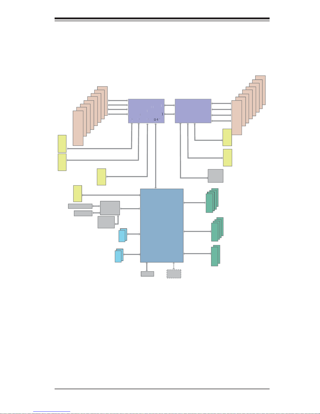
1-2 Serverboard Features
At the heart of the SuperServer 1027GR-72RT2+/72R2+/TRT2+/TR2+ server is the
X9DRG-HF+II/X9DRG-HFT+II , a dual processor serverboard based on the Intel
C602 chipset. Below are the main features of the X9DRG-HF+II/X9DRG-HFT+II .
(See Figure 1-1 for a block diagram of the chipset).
Processors
The X9DRG-HF+II/X9DRG-HFT+II supports two Intel E5-2600 series processors in
LGA 2011 sockets (Socket R). Please refer to the serverboard description pages on
our web site for a complete listing of supported processors (www.supermicro.com).
Memory
The X9DRG-HF+II/X9DRG-HFT+II has 16 DIMM slots that can support up to 512
GB of registered ECC DDR3-1600/1333/1066 MHz RDIMMs or 128 GB of ECC/
non-ECC UDIMMs. Modules of the same size and speed are recommended. See
Chapter 5 for details.
Serial ATA
The serverboard supports a 10-port SATA subsystem, which is RAID 0, 1, 5 and
10 supported. Two of these are SATA 3.0 ports and eight are SATA 2.0 ports. The
SATA drives are hot-swappable units.
PCI Expansion Slots
The X9DRG-HF+II/X9DRG-HFT+II has four PCI-Express 3.0 x16 slots to support
three double-width GPU cards. Additional slots support one PCI-Express 3.0 x8 (in
x16 slot) and one PCI-Express 2.0 x4 (in x8 slot). Note that both CPUs must be
installed for full use of the PCI-E slots.
Onboard Controllers/Ports
The rear I/O ports include a VGA (monitor) port, two USB 2.0 ports, two Gb Ethernet LAN ports (plus two 10 Gb ports on the X9DRG-HFT+II) and one dedicated
IPMI LAN port.
IPMI
IPMI (Intelligent Platform Management Interface) is a hardware-level interface specifi cation that provides remote access, monitoring and administration for Supermicro

1-3
Chapter 1: Introduction
server platforms. IPMI allows server administrators to view a server’s hardware
status remotely, receive an alarm automatically if a failure occurs, and power cycle
a system that is non-responsive.
1-3 Server Chassis Features
System Power
The SC118GH-R1K66B features a high-effi ciency 1600W redundant power sup-
ply. One power module may be removed without shutting down the system. See
Chapter 6 for details.
SATA Subsystem
The SC118GH-R1K66B chassis includes four 2.5" drive bays, which may be used
to house ho t-swappa ble SATA dr ives. R AID 0, 1, 5 and 10 are supp orte d (RA ID
5 is not supp or ted with L inux OS).
Front Control Panel
The control panel provides a system monitoring and control interface. LEDs indicate
system power, HDD activity, network activity, system overheat, UID and power
supply failure. A main power button and a system reset button are also included.
Cooling System
The SC118GH-R1K66B has an innovative cooling design that includes ten 4-cm
counter-rotating PWM (Pulse Width Modulated) fans. The power supply module
also includes a cooling fan. All chassis and power supply fans operate continuously.
These GPU servers include an air shroud (one for each GPU card) to further help
cool the GPUs.
1-4
SUPERSERVER 1027GR-72RT2+/72R2+/TRT2+/TR2+ User's Manual
1-4 GPU Subsystem
The 1027GR-72RT2+/72R2+/TRT2+/TR2+ server represents one of Supermicro's
massively parallel processing multiple-GPU servers, with support for up to three
GPUs. NVIDIA® Fermi™ and Kepler™ GPUs place this system at the forefront of
today's GPU computing solutions.
Please refer to the NVIDIA web site (
www.nvidia.com) for details on Fermi GPUs.
Notes
The 1027GR-72RT2+/72R2+/TRT2+/TR2+ all support NVIDIA M2090 and M2075
GPUs and K10, K20 and K20X (Kepler) GPUs. All four server models also include
SATA and 1 Gb Ethernet ports. The differences between the four models are as
follows:
1027GR-72RT2+: includes SAS (with add-on card controller) and 10 Gb Ethernet/
1027GR-72R2+: includes SAS (with add-on card controller)
1027GR-TRT2+: includes 10 Gb Ethernet.
1027GR-TR2+: basic features (no SAS and no 10 Gb Ethernet).
Note: NVIDIA Kepler™ GPUs (requires their own mounting brackets for installation:
p/n MCP-240-00117-0N)
1-5
Chapter 1: Introduction
VGA Port
SLOT 2
i350/X540
LAN
SLOT 6
SLOT 5
PCI-E X8
#8
#9
#7
#6
#4
#5
i_SATA
#0
#1
#2
#3
USB 2.0
USB
#0
#1
2 in Rear
Panel
3.0 Gb/S
For PORT 2~5
6.0 Gb/S
For PORT 0/1
S_SATA3
PORTs#0~3
800/1066/1333/1600
800/1066/1333/1600
DDRIII
P1
P1
P0
P0
#0-4
#0-3
#0-2
#0-1
DDRIII
#1-4
#1-3
#1-2
#1-1
QPI
8G
SLOT 1
Sandybridge-EP
PCH
PATSBURG
SSB-A or B
PORTs#0~5
PCI-E X16 Gen3
SATA
DMI2
LANE1/2/3/4
SPI
DMI2
#0-5
#0-6
#0-7
#0-8 #1-5
#1-6
#1-7
#1-8
i_SATA
SATA3
SATA2
3.0 Gb/S
BMC
WPCM450
PCI-E X16
PCI-E X16 Gen3
PCI
SATA2
2IMD2IMD
Sandybridge-EP
8 SNB CORE
DDR-III
8 SNB CORE
DDR-III
QPI
8G
4GB/s
PCI-E X16
VGA
PCI-E X8 Gen3
SLOT 4
PCI-E X16
PCI-E X16
SAS
PCI-E X8 Gen3
PCI-E X16 Gen3
PCI-E X16 Gen3
#1 #2 #3
#2 #3 #1
Dedicated Lan
Internal
COM Port
Header
PCI-E X4 Gen2
PCI-E X4
PCI
SLOT 3
CPU 2
CPU 1
SIO
W83527
P
1
P
0
S
andybridge-EP
2MIDM
8 S
NB
COR
E
DDR-III
#2#3#1
CPU 1
USB 2.0
USB
#8
#9
2 in Front
Panel
Figure 1-1. Intel C602 Chipset:
System Block Diagram
Note: This is a general block diagram. Please see Chapter 5 for details.

1-6
SUPERSERVER 1027GR-72RT2+/72R2+/TRT2+/TR2+ User's Manual
1-4 Contacting Supermicro
Headquarters
Address: Super Micro Computer, Inc.
980 Rock Ave.
San Jose, CA 95131 U.S.A.
Tel: +1 (408) 503-8000
Fax: +1 (408) 503-8008
Email: marketing@supermicro.com (General Information)
support@supermicro.com (Technical Support)
Web Site:
www.supermicro.com
Europe
Address: Super Micro Computer B.V.
Het Sterrenbeeld 28, 5215 ML
's-Hertogenbosch, The Netherlands
Tel: +31 (0) 73-6400390
Fax: +31 (0) 73-6416525
Email: sales@supermicro.nl (General Information)
support@supermicro.nl (Technical Support)
rma@supermicro.nl (Customer Support)
Asia-Pacifi c
Address: Super Micro Computer, Inc.
3F, No. 150, Jian 1st Rd.
Zhonghe Dist., New Taipei City 23511
Taiwan (R.O.C)
Tel: +886-(2) 8226-3990
Fax: +886-(2) 8226-3992
Web Site:
www.supermicro.com.tw
Technical Support:
Email: support@supermicro.com.tw
Tel: +886-(2)-8226-3990
Chapter 2: Server Installation
2-1
Chapter 2
Server Installation
2-1 Overview
This chapter provides a quick setup checklist to get your system up and running.
Following these steps in the order given should enable you to have the system
operational within a minimum amount of time. This quick setup assumes that your
system has come to you with the processors and memory preinstalled. If your system is not already fully integrated with a serverboard, processors, system memory
etc., please turn to the chapter or section noted in each step for details on installing
specifi c components.
2-2 Unpacking the System
You should inspect the box the system was shipped in and note if it was damaged
in any way. If the server itself shows damage you should fi le a damage claim with
the carrier who delivered it.
Decide on a suitable location for the rack unit that will hold the server. It should
be situated in a clean, dust-free area that is well ventilated. Avoid areas where
heat, electrical noise and electromagnetic fi elds are generated. You will also need
it placed near a grounded power outlet. Read the Rack and Server Precautions in
the next section.
2-3 Preparing for Setup
The box the server was shipped in should include two sets of rail assemblies, two
rail mounting brackets and the mounting screws you will need to install the system
into the rack. Follow the steps in the order given to complete the installation process
in a minimum amount of time. Please read this section in its entirety before you
begin the installation procedure outlined in the sections that follow.
Choosing a Setup Location
• Leave enough clearance in front of the rack to enable you to open the front door
completely (~25 inches) and approximately 30 inches of clearance in the back
of the rack to allow for suffi cient airfl ow and ease in servicing.This product is for
installation only in a Restricted Access Location (dedicated equipment rooms,
service closets and the like).

2-2
SUPERSERVER 1027GR-72RT2+/72R2+/TRT2+/TR2+ User's Manual
• This product is not suitable for use with visual display work place devices
acccording to §2 of the the German Ordinance for Work with Visual Display Units.
2-4 Warnings and Precautions!
Rack Precautions
• Ensure that the leveling jacks on the bottom of the rack are fully extended to
the fl oor with the full weight of the rack resting on them.
• In single rack installation, stabilizers should be attached to the rack. In multiple
rack installations, the racks should be coupled together.
• Always make sure the rack is stable before extending a component from the
rack.
• You should extend only one component at a time - extending two or more si-
multaneously may cause the rack to become unstable.
• Rack-mounted equipment should not be used as a shelf or work space.
Server Precautions
• Review the electrical and general safety precautions in Chapter 4.
• Determine the placement of each component in the rack before you install the
rails.
• Install the heaviest server components on the bottom of the rack fi rst, and then
work up.
• Use a regulating uninterruptible power supply (UPS) to protect the server from
power surges, voltage spikes and to keep your system operating in case of a
power failure.
• Allow the hot plug SATA drives and power supply modules to cool before touch-
ing them.
• Always keep the rack's front door and all panels and components on the servers
closed when not servicing to maintain proper cooling.
Chapter 2: Server Installation
2-3
Rack Mounting Considerations
Ambient Operating Temperature
If installed in a closed or multi-unit rack assembly, the ambient operating temperature of the rack environment may be greater than the ambient temperature of the
room. Therefore, consideration should be given to installing the equipment in an
environment compatible with the manufacturer’s maximum rated ambient temperature (Tmra).
Reduced Airfl ow
Equipment should be mounted into a rack so that the amount of airfl ow required
for safe operation is not compromised.
Mechanical Loading
Equipment should be mounted into a rack so that a hazardous condition does not
arise due to uneven mechanical loading.
Circuit Overloading
Consideration should be given to the connection of the equipment to the power
supply circuitry and the effect that any possible overloading of circuits might have
on overcurrent protection and power supply wiring. Appropriate consideration of
equipment nameplate ratings should be used when addressing this concern.
Reliable Ground
A reliable ground must be maintained at all times. To ensure this, the rack itself
should be grounded. Particular attention should be given to power supply connections other than the direct connections to the branch circuit (i.e. the use of power
strips, etc.).
Warning! To prevent bodily injury when mounting or servicing this unit in a
rack, you must take special precautions to ensure that the system remains
stable. The following guidelines are provided to ensure your safety:
• This unit should be mounted at the bottom of the rack if it is the only unit in
the rack.
• When mounting this unit in a partially fi lled rack, load the rack from the bottom
to the top with the heaviest component at the bottom of the rack.
• If the rack is provided with stabilizing devices, install the stabilizers before
mounting or servicing the unit in the rack.
2-4
SUPERSERVER 1027GR-72RT2+/72R2+/TRT2+/TR2+ User's Manual
2-5 Installing the System into a Rack
This section provides information on installing the SC1 18GH chassis into a rack unit
with the rails provided. There are a variety of rack units on the market, which may
mean that the assembly procedure will differ slightly. You should also refer to the
installation instructions that came with the rack unit you are using.
Note: This rail will fi t a rack between 26" and 33.5" deep.
Stability hazard. The rack stabilizing mechanism must be in place, or the
rack must be bolted to the fl oor before you slide the unit out for servicing.
Failure to stabilize the rack can cause the rack to tip over.
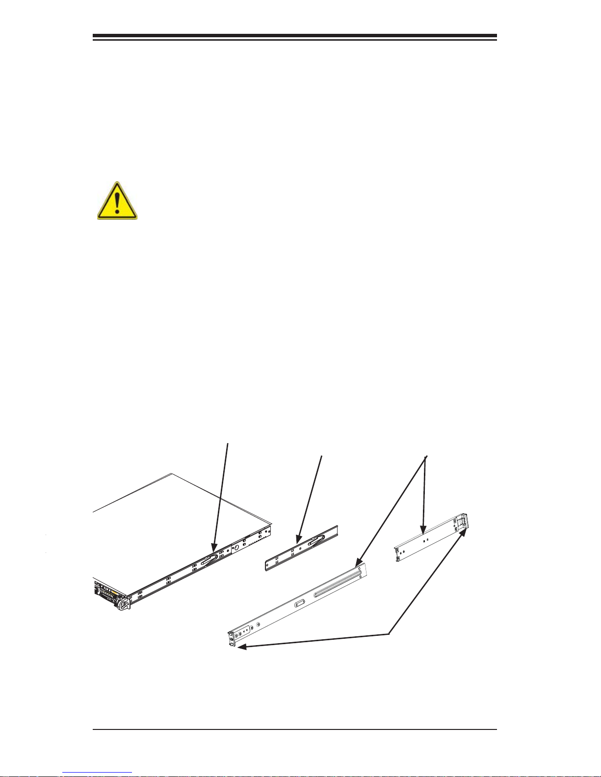
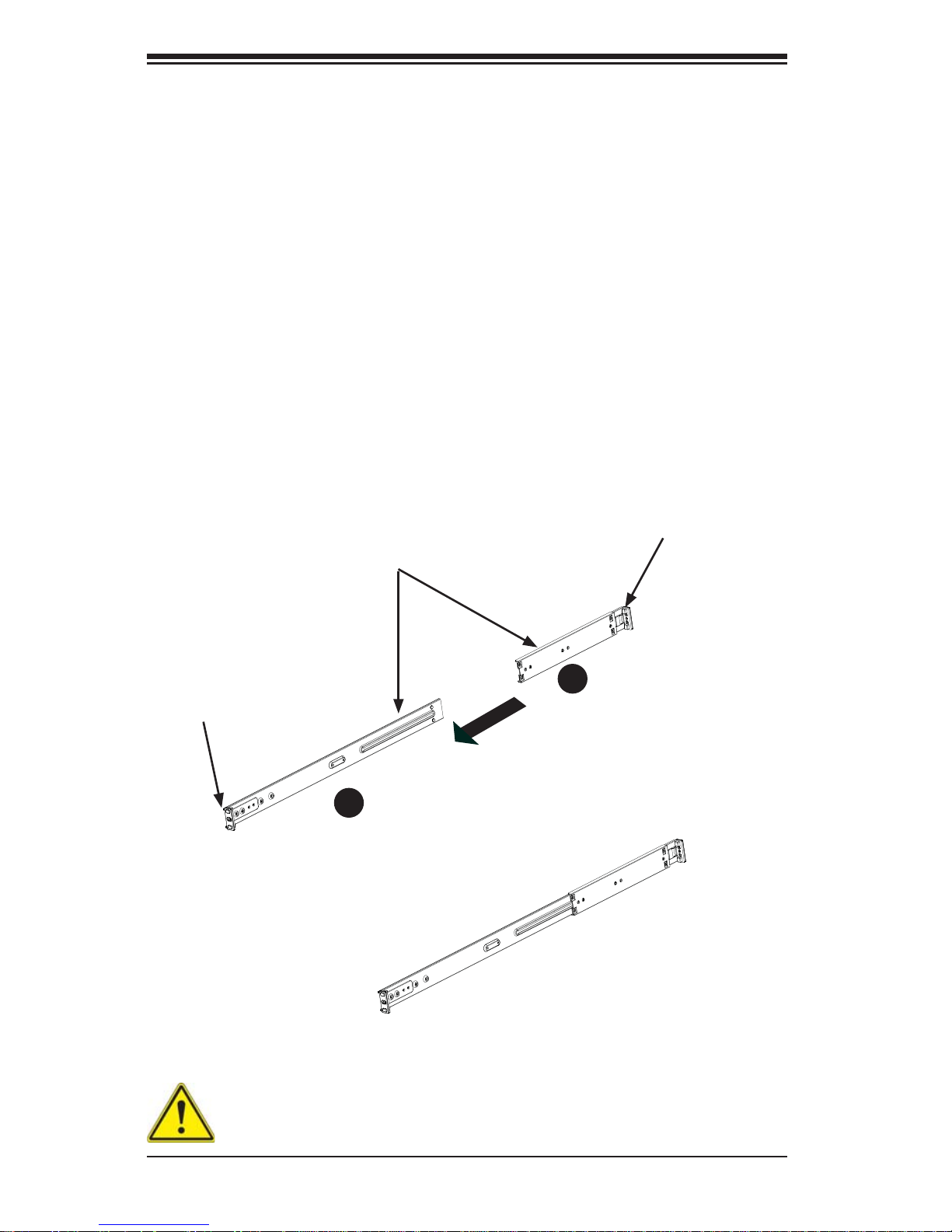
Identifying the Sections of the Rack Rails
The chassis package includes two rack rail assemblies in the rack mounting kit.
Each assembly consists of two sections: an inner fi xed chassis rail that secures
directly to the server chassis and an outer fi xed rack rail that secures directly to
the rack itself.
Figure 2-1. Identifying the Sections of the Rack Rails
Inner Rail
Extension:
attach to the
chassis
Outer Rails:
slide together, then
attach to the front
and rear brackets
Inner Rail (preattached
to the chassis)
Front and Rear
Brackets: attach to
the rack
Chapter 2: Server Installation
2-5
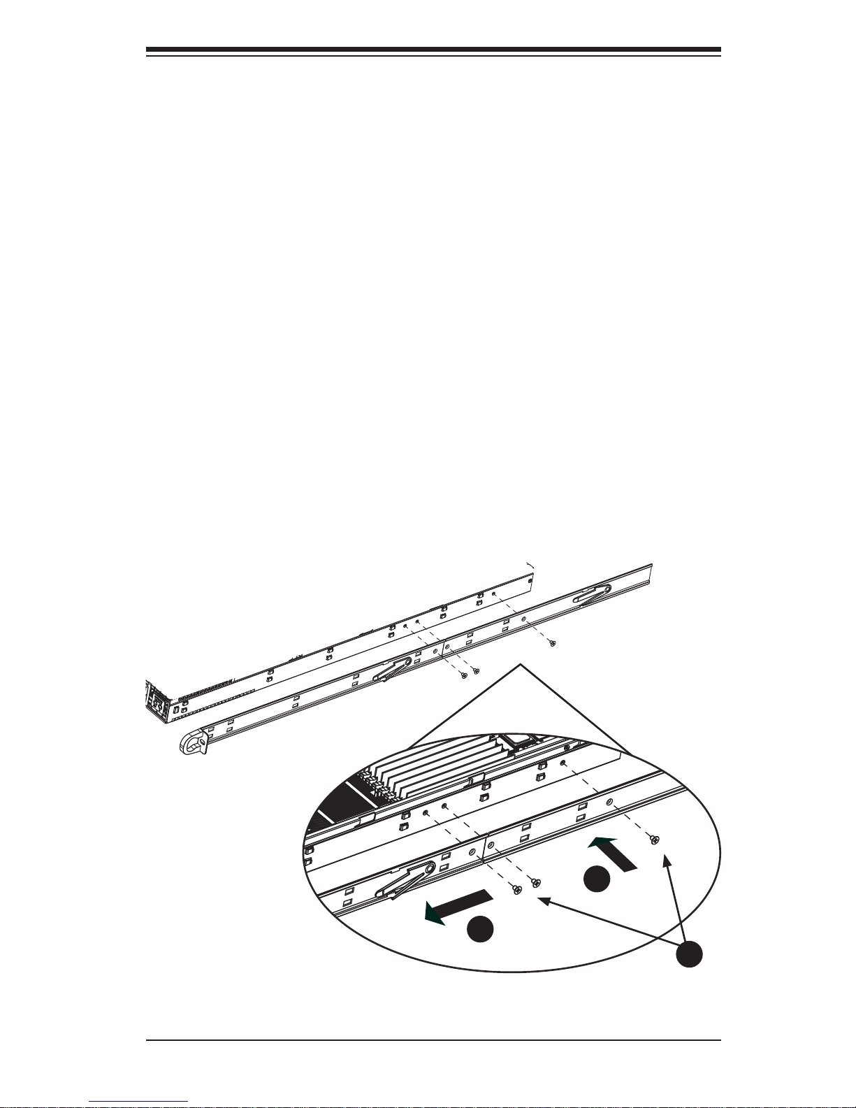
Figure 2-2. Installing the Inner Rails
1
1
1
2
1
3
Installing the Inner Rail Extensions
The SC118GH chassis includes a set of inner rack rails in two sections: inner rails
(A) and inner rail extensions (B). The inner rails are preattached and do not interfere
with normal use of the chassis if you decide not to install to a server rack. Attaching
the inner rail extensions to to the inner rails stabilizes the chassis within the rack.
Installing the Inner Rail Extensions
1. Place the inner rail extensions (B) over the preattached inner rails (A) which
are attached to the side of the chassis. Align the hooks of the inner rail with
the rail extension holes. Make sure the extension faces "outward" just like the
inner rail.
2. Slide the extension toward the front of the chassis.
3. Secure the chassis with screws as illustrated.
4. Repeat steps 1-3 for the other inner rail extension.
2-6
SUPERSERVER 1027GR-72RT2+/72R2+/TRT2+/TR2+ User's Manual
Figure 2-3. Assembling the Outer Rails
Assembling the Outer Rails
Each outer rail is in two sections that must be assembled before mounting on to
the rack.
Assembling the Outer Rails
1. Identify the left and right outer rails by examining the ends, which bend
outward.
2. Slide the front section of the outer rail (A), into the rear section of the outer
rail (B).
Secure to the
front of the rack
Secure to the
rear of the rack
Slide outer rails
together
Outer rail assembled
Assembling the sections of
the outer rail
1
A
1
B
Warning: do not pick up the server with the front handles. They are de-
signed to pull the system from a rack only.
Chapter 2: Server Installation
2-7
Figure 2-4. Installing the Outer Rails to the Rack
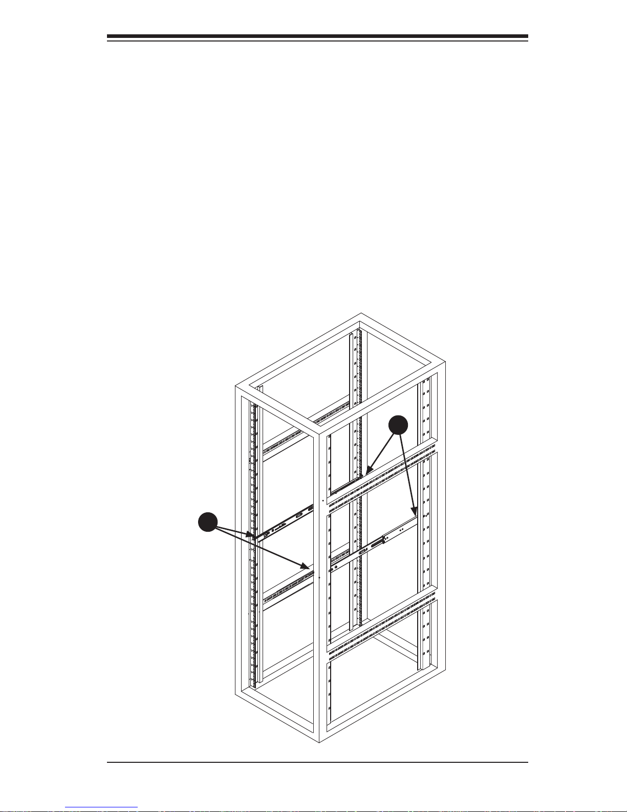
Installing the Outer Rails onto the Rack
Outer Rail Installation
1. Adjust the outer rails to the proper length so that the outer rail fi ts snugly
within the rack.
2. Align the holes on the front of the outer rail, with the holes on the front of the
rack (C) and secure with the screws provided.
3. Align the holes on the rear of the outer rail to the holes on the rack (D) and
secure with the screws provided.
4. Repeat the procedure with the second outer rail assembly.
1
C
1
D
2-8
SUPERSERVER 1027GR-72RT2+/72R2+/TRT2+/TR2+ User's Manual
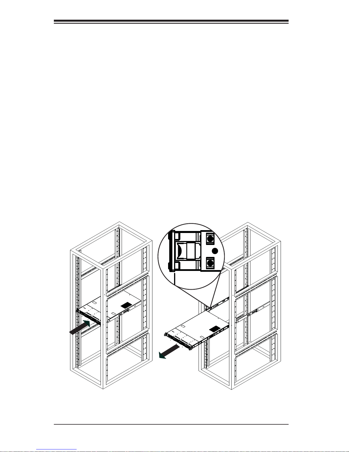
Installing and Removing the Chassis From a Rack
Installation into a Rack
1. Slide the inner rail extensions into the front of the outer rails.
2. Push the chassis backward into the rack until it clicks into the locked postion.
Removing the Chassis From a Rack
1. Press the outer rail latch to release the chassis.
2. Carefully slide the chassis forward, off the outer rails and out of the chassis.
Figure 2-5. Server Installation and Removal
Outer Rail
Latch
Chapter 2: Server Installation
2-9
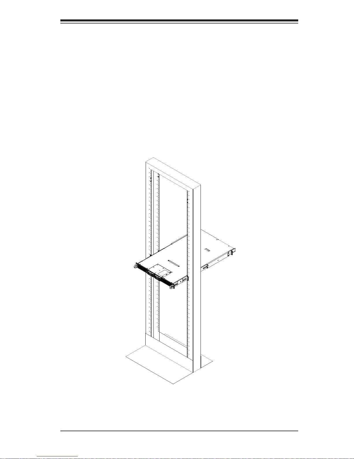
Installing the Server into a Telco Rack
Optional brackets are needed to install the server to a telco (open type) rack.
To install the server into a Telco type rack, use the two L-shaped brackets on either
side of the chassis (four total). First, determine how far follow the server will extend
out the front of the rack. Larger chassis should be positioned to balance the weight
between front and back. If a bezel is included on your server, remove it. Then attach the two front brackets to each side of the chassis, then the two rear brackets
positioned with just enough space to accommodate the width of the telco rack. Finish
by sliding the chassis into the rack and tightening the brackets to the rack.
Figure 2-6. Installing the Server into a Telco Rack
Note: Figures are for illustrative purposes only. Servers should always be installed
into racks starting at the bottom.

2-10
SUPERSERVER 1027GR-72RT2+/72R2+/TRT2+/TR2+ User's Manual
Notes
Chapter 3: System Interface
3-1
Power
The main power button is used to apply or remove power from the power supply
to the server system. Turning off system power with this button removes the main
power but keeps standby power supplied to the system.
Chapter 3
System Interface
3-1 Overview
There are several LEDs on the control panel as well as others on the drive carriers to keep you constantly informed of the overall status of the system as well as
the activity and health of specifi c components. There are also two buttons on the
chassis control panel. This chapter explains the meanings of all LED indicators and
the appropriate response you may need to take.
3-2 Control Panel Buttons
There are two push-buttons located on the front of the chassis: a reset button and
a power on/off button.
Reset
Use the reset button to reboot the system.
3-2
SUPERSERVER 1027GR-72RT2+/72R2+/TRT2+/TR2+ User's Manual
1
2
NIC1
Indicates network activity on GLAN1 when fl ashing .
3-3 Control Panel LEDs
The two control panels are located on the front of the SC118GH chassis. Each
control panel has six LEDs. These LEDs provide critical information related to different parts of the system. This section explains what each LED indicates when
illuminated and any action that may be required..
NIC2
Indicates network activity on GLAN2 when fl ashing .
Overheat/Fan Fail/UID LED
When this LED fl ashes it indi c ates a f an fai lur e. Whe n c onti nuo usly o n (not fl ash-
ing) it indicates an overheat condition, which may be caused by cables obstructing
the airfl ow in the system or the ambient room temperature being too warm. Check
the rout ing of the cab les and make sure that a ll fans are pres ent and operati ng
norma lly. Also ch eck to make sur e that the a ir shrou ds are inst alled a nd that th e
top cover i s on. Final ly, verify t hat the he atsink s are inst alled p rope rly.
This LED will rema in fl ashing or on as long as the overheat condition exists. When
used with a UID-compatible motherboard, the UID function is used to turn on or off
the blue light function of the the LED. Once the blue light is activated through the
system software, the unit can be easily located in very large racks and server banks.
Chapter 3: System Interface
3-3
3-4 Drive Carrier LEDs
• Green: Eac h hard drive c arrier (fo r use with SATA drives) has a gree n LED.
When ill umin ated, th is gre en LED (on th e fro nt of the S ATA drive car r ier) ind icates drive activity. A connection to the backplane enables this LED to blink on
and of f w h e n t hat p a rtic u l ar d rive is bei ng a cces s e d. Please refer to Chapter 6
for instructions on replacing failed SATA drives.
• Red: The red LED to indicate a SATA drive failure. If one of the SATA drives
fail, you should be notifi ed by your system management software. Please refer
to Chapter 6 for instructions on replacing failed SATA drives.
HDD
This ligh t indic ates SATA and/or per ipher al drive ac tivit y whe n fl ashing.
Power
Indic ates power is bein g supplied to the sy stem's power supply u nits. This LED
should normally be illuminated when the system is operating.

3-4
SUPERSERVER 1027GR-72RT2+/72R2+/TRT2+/TR2+ User's Manual
Notes
4-1
Chapter 4: Warning Statements for AC Systems
Chapter 4
Standardized Warning Statements for AC Systems
4-1 About Standardized Warning Statements
The following statements are industry standard warnings, provided to warn the user
of situations which have the potential for bodily injury. Should you have questions
or experience difficulty, contact Supermicro's Technical Support department
for assistance. Only certifi ed technicians should attempt to install or confi gure
components.
Read this appendix in its entirety before installing or confi guring components in the
Supermicro chassis.
These warnings may also be found on our web site at http://www.supermicro.com/
about/policies/safety_information.cfm.
Warning!
This warning symbol means danger. You are in a situation that could cause bodily
injury. Before you work on any equipment, be aware of the hazards involved with
electrical circuitry and be familiar with standard practices for preventing accidents.
Warning Defi nition
警告の定義
この警告サインは危険を意味します。
人身事故につながる可能性がありますので、いずれの機器でも動作させる前に、
電気回路に含まれる危険性に注意して、標準的な事故防止策に精通して下さい。
此警告符号代表危险。
您正处于可能受到严重伤害的工作环境中。在您使用设备开始工作之前,必须充分
意识到触电的危险,并熟练掌握防止事故发生的标准工作程序。请根据每项警告结
尾的声明号码找到此设备的安全性警告说明的翻译文本。
此警告符號代表危險。
您正處於可能身體可能會受損傷的工作環境中。在您使用任何設備之前,請注意觸
電的危險,並且要熟悉預防事故發生的標準工作程序。請依照每一注意事項後的號
碼找到相關的翻譯說明內容。

4-2
SUPERSERVER 1027GR-72RT2+/72R2+/TRT2+/TR2+ User's Manual
Warnung
WICHTIGE SICHERHEITSHINWEISE
Dieses Warnsymbol bedeutet Gefahr. Sie befi nden sich in einer Situation, die zu
Verletzungen führen kann. Machen Sie sich vor der Arbeit mit Geräten mit den
Gefahren elektrischer Schaltungen und den üblichen Verfahren zur Vorbeugung
vor Unfällen vertraut. Suchen Sie mit der am Ende jeder Warnung angegebenen
Anweisungsnummer nach der jeweiligen Übersetzung in den übersetzten
Sicherheitshinweisen, die zusammen mit diesem Gerät ausgeliefert wurden.
BEWAHREN SIE DIESE HINWEISE GUT AUF.
INSTRUCCIONES IMPORTANTES DE SEGURIDAD
Este símbolo de aviso indica peligro. Existe riesgo para su integridad física. Antes
de manipular cualquier equipo, considere los riesgos de la corriente eléctrica y
familiarícese con los procedimientos estándar de prevención de accidentes. Al
fi nal de cada advertencia encontrará el número que le ayudará a encontrar el texto
traducido en el apartado de traducciones que acompaña a este dispositivo.
GUARDE ESTAS INSTRUCCIONES.
IMPORTANTES INFORMATIONS DE SÉCURITÉ
Ce symbole d'avertissement indique un danger. Vous vous trouvez dans une
situation pouvant entraîner des blessures ou des dommages corporels. Avant
de travailler sur un équipement, soyez conscient des dangers liés aux circuits
électriques et familiarisez-vous avec les procédures couramment utilisées pour
éviter les accidents. Pour prendre connaissance des traductions des avertissements
fi gurant dans les consignes de sécurité traduites qui accompagnent cet appareil,
référez-vous au numéro de l'instruction situé à la fi n de chaque avertissement.
CONSERVEZ CES INFORMATIONS.
ןונקת תורהצהאהרהז
ןה תואבה תורהצהא ינפמ שמתשמה תא ריהזהל תנמ לע ,היישעתה ינקת יפ לע תורהז הלבח
ה וא תולאש שיו הדימב .תירשפא תיזיפי ,יהשלכ היעבב תולקתרוציל שי הכימת תקלחמ םע רשק
רידגהל וא ןיקתהל םיאשר דבלב םיכמסומ םיאנכט .ורקימרפוס לש תינכט תאה .םיביכר
אורקל שי .ורקימרפוס יזראמב םיביכרה
תרדגה וא תנקתה ינפל ואולמב חפסנה תא
 Loading...