

Supero SuperRack User Manual
®
SUPER
SuperRack™
USER'S MANUAL
Revision 1.0

Manual Revision 1.0
Release Date: September 20, 2011
The information in this User’s Manual has been carefully reviewed and is believed to be accurate.
The vendor assumes no responsibility for any inaccuracies that may be contained in this document,
makes no commitment to update or to keep current the information in this manual, or to notify any
person or organization of the updates. Please Note: For the most up-to-date version of this
manual, please see our web site at www.supermicro.com.
Super Micro Computer, Inc. ("Supermicro") reserves the right to make changes to the product
described in this manual at any time and without notice. This product, including software and
documentation, is the property of Supermicro and/or its licensors, and is supplied only under a
license. Any use or reproduction of this product is not allowed, except as expressly permitted by
the terms of said license.
IN NO EVENT WILL SUPERMICRO BE LIABLE FOR DIRECT, INDIRECT, SPECIAL, INCIDENTAL,
SPECULATIVE OR CONSEQUENTIAL DAMAGES ARISING FROM THE USE OR INABILITY TO
USE THIS PRODUCT OR DOCUMENTATION, EVEN IF ADVISED OF THE POSSIBILITY OF
SUCH DAMAGES. IN PARTICULAR, SUPERMICRO SHALL NOT HAVE LIABILITY FOR ANY
HARDWARE, SOFTW ARE, OR DA TA STORED OR USED WITH THE PRODUCT, INCLUDING THE
COSTS OF REPAIRING, REPLACING, INTEGRATING, INSTALLING OR RECOVERING SUCH
HARDWARE, SOFTWARE, OR DATA.
Any disputes arising between manufacturer and customer shall be governed by the laws of Santa
Clara County in the State of California, USA. The State of California, County of Santa Clara shall
be the exclusive venue for the resolution of any such disputes. Super Micro's total liability for all
claims will not exceed the price paid for the hardware product.
FCC Statement: This equipment has been tested and found to comply with the limits for a Class
A digital device pursuant to Part 15 of the FCC Rules. These limits are designed to provide
reasonable protection against harmful interference when the equipment is operated in a commercial
environment. This equipment generates, uses, and can radiate radio frequency energy and, if not
installed and used in accordance with the manufacturer’s instruction manual, may cause harmful
interference with radio communications. Operation of this equipment in a residential area is likely
to cause harmful interference, in which case you will be required to correct the interference at your
own expense.
California Best Management Practices Regulations for Perchlorate Materials: This Perchlorate
warning applies only to products containing CR (Manganese Dioxide) Lithium coin cells. “Perchlorate
Material-special handling may apply. See www.dtsc.ca.gov/hazardouswaste/perchlorate”
WARNING: Handling of lead solder materials used in this
product may expose you to lead, a chemical known to
the State of California to cause birth defects and other
reproductive harm.
Unless you request and receive written permission from Super Micro Computer, Inc., you may not
copy any part of this document.
Information in this document is subject to change without notice. Other products and companies
referred to herein are trademarks or registered trademarks of their respective companies or mark
holders.
Copyright © 2011 by Super Micro Computer, Inc.
All rights reserved.
Printed in the United States of America

iii
Preface
Preface
About This Manual
This manual is written for professional system integrators and PC technicians. It
provides information for the installation and use of the SuperRack™ system. Setup,
installation and maintainance should be performed by experienced technicians
only.
The SuperRack system is a high-end rack mount system that includes parts for
making different rack systems based upon any one of fi ve standard models of the
SuperRack.
Manual Organization
Chapter 1: Introduction
The fi rst chapter provides a overview of the SuperRack system and its various
models and components.
Chapter 2: SuperRack System Installation
This chapter describes the steps necessary to install the SuperRack system on site
and how to unship the SuperRack from its crate.
Chapter 3: Safety
You should thoroughly familiarize yourself with this chapter for a general overview
of safety precautions that should be followed when installing and servicing the
SuperRack.
Chapter 4: SuperRack Standard Models
This chapter provides detailed information about the features and elements of the
SuperRack system's standard models.
Appendix A: SuperRack System Specifi cations
This appendix contains specifi cations for the standard models of the SuperRack
system.

SuperRack Installation Manual
iv
Notes

v
Table of Contents
Chapter 1 Introduction
1-1 Overview .........................................................................................................1-1
1-2 SuperRack Features .......................................................................................1-2
1-3 Returning Merchandise for Service.................................................................1-2
1-4 Contacting Supermicro ....................................................................................1-3
Chapter 2 System Safety
2-1 Electrical Safety Precautions .......................................................................... 2-1
2-2 General Safety Precautions ............................................................................2-2
2-3 ESD Precautions ............................................................................................. 2-3
2-4 Rack Precautions ............................................................................................2-4
Chapter 3 Rack Setup and Installation
3-1 Overview .........................................................................................................3-1
3-2 Inspecting the Rack and Shipping Crate ........................................................3-1
3-3 Preparing for Setup ......................................................................................... 3-1
Location Setup Recommendations .................................................................3-1
Rack Precautions ............................................................................................3-2
Server or Component Precautions..................................................................3-2
3-4 Unpacking the SuperRack from its Shipping Carton ......................................3-3
3-5 Installing EIA Mounting Posts .........................................................................3-7
Chapter 4 SuperRack Models
4-1 SuperRack Model SRK-42BF-01 ...................................................................4-1
4-2 SuperRack Model SRK-42OR-01 .................................................................. 4-3
4-3 SuperRack Model SRK-42OR-02 .................................................................. 4-5
4-4 SuperRack Model SRK-42SE-01 ................................................................... 4-7
4-5 SuperRack Model SRK-42SE-02 ................................................................... 4-9
Chapter 5 Optional Accessories
5-1 Tools ................................................................................................................ 5-2
Screw Bag ....................................................................................................... 5-2
5-2 Accessories and Modifi cation Procedures ...................................................... 5-3
Doors ...............................................................................................................5-3
Top and Side Panels .......................................................................................5-6
Installing and Uninstalling Top Panels ....................................................... 5-8
Types of Top Panels ................................................................................... 5-9
Expansion Units ............................................................................................5-10
EIA Posts .......................................................................................................5-12
Changing Casters ......................................................................................... 5-15
SuperRack Installation Manual

vi
Shelves and Slide Rails ................................................................................ 5-16
Component Installation .................................................................................5-18
Fan Modules ................................................................................................. 5-18
Cable Management Troughs and Fiber Optic Pipes .................................... 5-18
Mounting a Vertical Plate ......................................................................... 5-20
Mounting a Cable Management Trough to a Vertical Plate ..................... 5-21
Appendix A SuperRack System Parts List
Table of Contents
Chapter 1
Introduction
1-1 Overview
The SuperRack system consists of fi ve standard models of racks that are assembled
from the same pool of components and accessories. The below table lists the
available standard rack models in the SuperRack system and their described
uses.
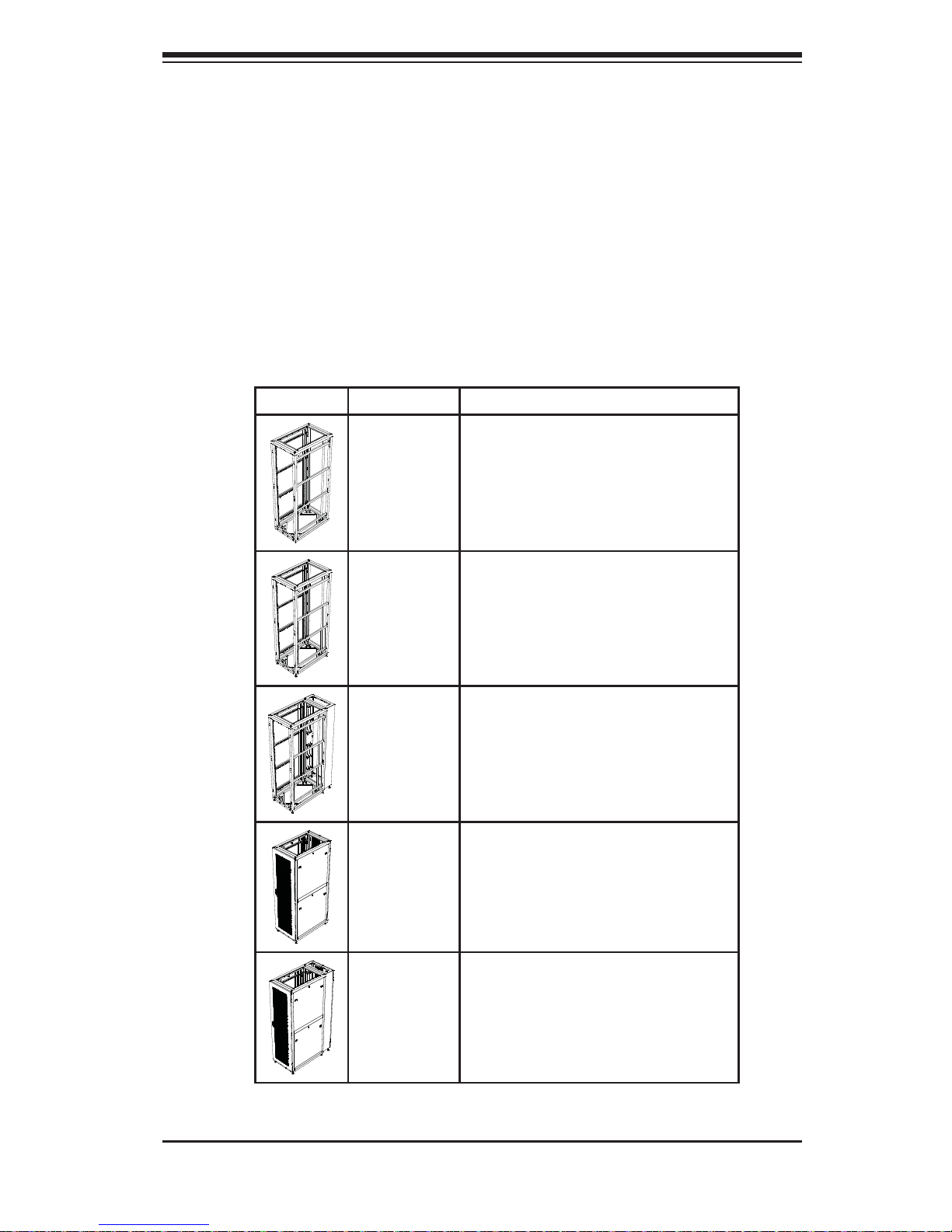
Picture Rack Model Description
SBK-42BF-01 42U Basic Frame system
SRK-42OR-01 42U Open Frame system
SRK-420R-02 42U Open Frame with Rear Expansion system
SRK-42SE-01 42U Enclosure system
SRK-42SE-02 42U Enclosure with Rear Expansion system
For details on these models see Chapter 4. Additional components or accessories
can be added or subtracted from these standard models by the user.
Chapter 1: Introduction
1-1

1-2
SuperRack Installation Manual
1-2 SuperRack Features
The SuperRack system offers the following features:
• Supports quick release square mounting holes with adapters for round screw
mounts
• User conventional cabling and cabling identifi cation designs
• Front, rear and side expansion units provide modular solutions for any system
confi guration
• Static load rating of 551 1.55lbs (2500kg) to support high density rack components
• EIA standard 310D hardware
• Sturdy fully welded construction
• Wide range of fl exible accessory options
1-3 Returning Merchandise for Service
A receipt or copy of your invoice marked with the date of purchase is required
before any warranty service will be rendered. You can obtain service by calling your
vendor for a Returned Merchandise Authorization (RMA) number. When returning
to the manufacturer, the RMA number should be prominently displayed on the
outside of the shipping carton, and mailed prepaid or hand-carried. Shipping and
handling charges will be applied for all orders that must be mailed when service
is complete.
For faster service, RMA authorizations may be requested online at:
http://www. supermicro.com/support/rma/
Whenever possible, repack the chassis in the original Supermicro carton, using the
original packaging material. If these are no longer available, be sure to pack the
chassis securely, using packaging material to surround the chassis so that it does
not shift within the carton and become damaged during shipping.
This warranty only covers normal consumer use and does not cover damages
incurred in shipping or from failure due to the alteration, misuse, abuse or improper
maintenance of products. During the warranty period, contact your distributor fi rst for
any product problems. The Supermicro warranty can be found on our website at:
http://www.supermicro.com/support/Warranty/

1-3
Chapter 1: Introduction
1-4 Contacting Supermicro
Headquarters
Address: Super Micro Computer, Inc.
980 Rock Ave.
San Jose, CA 95131 U.S.A.
Tel: +1 (408) 503-8000
Fax: +1 (408) 503-8008
Email: marketing@supermicro.com (General Information)
support@supermicro.com (Technical Support)
Web Site: www.supermicro.com
Europe
Address: Super Micro Computer B.V.
Het Sterrenbeeld 28, 5215 ML
's-Hertogenbosch, The Netherlands
Tel: +31 (0) 73-6400390
Fax: +31 (0) 73-6416525
Email: sales@supermicro.nl (General Information)
support@supermicro.nl (Technical Support)
rma@supermicro.nl (Customer Support)
Asia-Pacifi c
Address: Super Micro Computer, Inc.
4F, No. 232-1, Liancheng Rd.
Chung-Ho 235, Taipei County
Taiwan, R.O.C.
Tel: +886-(2) 8226-3990
Fax: +886-(2) 8226-3991
Web Site: www.supermicro.com.tw
Technical Support:
Email: support@supermicro.com.tw
Tel: +886-(2) 8226-5990

1-4
SuperRack Installation Manual
Notes
Chapter 2: Safety
2-1
2-1 Electrical Safety Precautions
!
Basic electrical safety precautions should be followed to protect yourself from harm
and the SuperRack system from damage:
• Be aware of the locations of the power on/off switch on the chassis as well
as the room's emergency power-off switch, disconnection switch or electrical
outlet. If an electrical accident occurs, you can then quickly remove power from
the system.
• Do not work alone when working with high voltage components.
• Power should always be disconnected from the system when removing
or installing main system components, such as a server system. When
disconnecting power, you should fi rst power down the operating system fi rst
and then unplug the power cords.
• When working around exposed electrical circuits, another person who is
familiar with the power-off controls should be nearby to switch off the power if
necessary.
• Use only one hand when working with powered-on electrical equipment. This
is to avoid making a complete circuit, which will cause electrical shock. Use
extreme caution when using metal tools, which can easily damage any electrical
components or circuit boards they come into contact with.
• Do not use mats designed to decrease static electrical discharge as protection
from electrical shock. Instead, use rubber mats that have been specifi cally
designed as electrical insulators.
• The power supply power cords must include a grounding plug and must be
plugged into grounded electrical outlets.
!
!
Warnings and Precautions!
Chapter 2
System Safety
SuperRack Installation Manual
2-2
• This product may be connected to an power system. In all cases, make sure
that the unit is also reliably connected to Earth (ground).
2-2 General Safety Precautions
!
Follow these rules to ensure general safety:
• Keep the area around the SuperRack system clean and free of clutter.
• The SuperRack system weighs up to 258.91 lbs (117.44 kg) empty, and has a
shipping weight of up to 331.08 lbs (150.18 kg). The system should be moved
on its casters.
• Place any system components and accessories that have been removed away
from the system or on a table so that they won't accidentally be stepped on.
• While working on the system, do not wear loose clothing such as neckties and
unbuttoned shirt sleeves, which can come into contact with electrical circuits or
be pulled into a cooling fan.
• Remove any jewelry or metal objects from your body, which are excellent metal
conductors that can create short circuits and harm you if they come into contact
with printed circuit boards or areas where power is present.
• After accessing the inside of the system, close the system back up and secure
it after ensuring that all connections have been made.
Chapter 2: Safety
2-3
2-3 ESD Precautions
!
Electrostatic discharge (ESD) is generated by two objects with different electrical
charges coming into contact with each other. An electrical discharge is created to
neutralize this difference, which can damage electronic com ponents and printed
circuit boards. The following measures are generally suffi cient to neutralize this
difference before contact is made to protect your equipment from ESD:
• Use a grounded wrist strap designed to prevent static discharge.
• Keep all components and printed circuit boards (PCBs) in their antistatic bags
until ready for use.
• Touch a grounded metal object before removing the board from the antistatic
bag.
• Do not let components or PCBs come into contact with your clothing, which may
retain a charge even if you are wearing a wrist strap.
• Handle a board by its edges only; do not touch its components, peripheral chips,
memory modules or contacts.
• When handling chips or modules, avoid touching their pins.
• Put the serverboard and peripherals back into their antistatic bags when not
in use.
• For grounding purposes, make sure your computer chassis provides excellent
conductivity between the power supply, the case, the mounting fasteners and
the serverboard.
SuperRack Installation Manual
2-4
2-4 Rack Precautions
!
Warning: To reduce the risk of personal injury or damage to the equipment, do not
attempt to move large equipment racks alone. Obtain adequate assistance to stabilize
the rack during movement or hire professional equipment riggers to move it.
Make sure to follow the below rack precautions:
• Ensure that the leveling jacks on the bottom of the rack are fully extended to
the fl oor with the full weight of the rack resting on them when the SuperRack
is setup in its location.
Caution: To reduce the risk of damage to the casters make sure that the full
weight of the rack rests on the leveling feet, and not on the casters. The casters
are designed only as an aid in moving the rack into position and are not designed
to support the weight of the rack, and may become damaged if relied upon to
support the rack.
• In single rack installation, stabilizers should be attached to the rack. In multiple
rack installations, the racks should be coupled together.
• Always make sure the rack is stable before extending a component from the
rack.
• You should extend only one component at a time – extending two or more
simultaneously may cause the rack to become unstable.

Chapter 3: Rack Setup and Installation
3-1
Chapter 3
Rack Setup and Installation
3-1 Overview
This chapter provides information on setting up and installing your SuperRack
system. It is assumed in this chapter that your SuperRack system is shipped
assembled and ready for installation on site. .
3-2 Inspecting the Rack and Shipping Crate
You should inspect the crate the SuperRack system was shipped in and note if it
was damaged in any way. After unshipping the SuperRack from the crate inspect
the SuperRack itself for any damage. If the rack itself shows damage you should
fi le a damage claim with the carrier who delivered it.
3-3 Preparing for Setup
Before setting up your SuperRack system, please review the following setup
information and considerations for the location where the SuperRack system will
be installed.
Location Setup Recommendations
Below are recommended requirements for the setup location:
• Location should have reliable local power and the utility should have the
availability to provide two alternate electrical feeds preferably from separate
sources
• Have a minimum of two routes for data and phone infrastructure into the
building
• Minimum one hour fi re rated walls
• Minimum 100+ PSF fl oor loading, or 200+ PSF fl oor loading to be determined
by equipment load
• Nine (9) feet raised fl oor to ceiling clear height minimum

3-2
SuperRack Installation Manual
• No exterior windows
• No overhead water pipes
• Power and Data cabling shall be in separate raceways overhead.
Rack Precautions
Equipment should be mounted into a rack so that a hazardous conditions do not
arise due to uneven mechanical loading.
Observe the following rack precautions
• Leave enough clearance in front of the rack to enable you to open the front
door completely (~25-inches).
• Allow approximately 30-inches of clearance in the back of the rack to allow for
suffi cient airfl ow and ease in servicing.
• Ensure that the leveling jacks on the bottom of the rack are fully extended to
the fl oor, with the full weight of the rack resting upon them.
• In single rack installation, stabilizers should be attached to the rack. In multiple
rack installations, the racks should be coupled together.
• Always make sure the rack is stable before extending a component from the
rack.
• You should extend only one component at a time – extending two or more
simultaneously may cause the rack to become unstable.
Server or Component Precautions
Below are server and component precautions to observe for all components installed
in the SuperRack system:
• Review the electrical and general safety precautions in Chapter 2.
• Determine the placement of each component in the rack before you install the
rails.
• Install the heaviest server components on the bottom of the rack fi rst, and then
work up.

Chapter 3: Rack Setup and Installation
3-3
• Use a regulating uninterruptible power supply (UPS) to protect the rack's servers
from power surges, voltage spikes and to keep your system operating in case
of a power failure.
• Allow any hot plug drives and power supply modules to cool before touching
them.
• Always keep the rack's front door (if installed) and all panels and components
on the servers closed when not servicing to maintain proper cooling.
3-4 Unpacking the SuperRack from its Shipping Carton
Use the procedure below to help you unpack the SuperRack system from its
shipping carton. The SuperRack comes mounted on a pallet with steel retaining
brackets, packaged in a cardboard shipping carton. It is reinforced with plastic
strapping, and with both an interior plastic bag and exterior plastic covering that is
secured by tape to protect it from damage.
Note: The drawing for this section are for illustration purposes only. They do not
necessarily refl ect the exact product(s) described in this manual.
Unpacking the SuperRack Shipping Carton
1. Inspect the shipping carton for damage. If you see any damage, contact your
shipping company.
Note: Make sure the crate is upright with the label arrow pointing upward.
2. Move the shipping carton to the SuperRack's deployment location.
Note: It is recommended that you use a lift or forklift for moving the SuperRack
to its fi nal location.
3-4
SuperRack Installation Manual
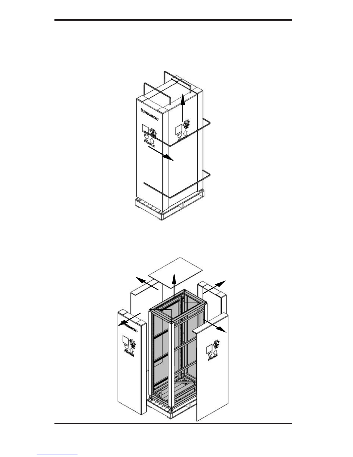
Figure 3-1. Remove Retaining Straps
3. Remove the outer plastic wrapping from the carton, then cut and remove the
retaining straps from the outside of the shipping carton (see Figure 3-1).
4. Remove the sides from the shipping carton (see Figure 3-2).
Figure 3-2. Remove Shipping Carton Sides
 Loading...