


SUPER
®
Dual Pentium Pro Processor
®
SUPER P6DNF
Single Pentium Pro Processor
SUPER P6SNF
USER’S MANUAL
®
Revision 2.1

The information in this User’s Manual has been carefully reviewed and is believed to be
accurate. The vendor assumes no responsibility for any inaccuracies that may be
contained in this document, makes no commitment to update or to keep current the
information in this manual, or to notify any person or organization of the updates.
SUPER P6DNF/P6SNF reserves the right to make changes to the product described in this
manual at any time and without notice. This product, including software, if any, and
documentation may not, in whole or in part, be copied, photocopied, reproduced, translated
or reduced to any medium or machine without prior written consent.
IN NO EVENT WILL SUPER P6DNF/P6SNF BE LIABLE FOR DIRECT, INDIRECT,
SPECIAL, INCIDENTAL, OR CONSEQUENTIAL DAMAGES ARISING FROM THE USE OR
INABILITY TO USE THIS PRODUCT OR DOCUMENTATION, EVEN IF ADVISED OF THE
POSSIBILITY OF SUCH DAMAGES. IN PARTICULAR, THE VENDOR SHALL NOT HAVE
LIABILITY FOR ANY HARDWARE, SOFTWARE, OR DATA STORED OR USED WITH THE
PRODUCT, INCLUDING THE COSTS OF THE REPAIRING, REPLACING, OR
RECOVERING SUCH HARDWARE, SOFTWARE, OR DATA.
Copyright © 1996 by SUPER P6DNF/P6SNF
All rights reserved.
Printed in the United States of America.
Unless you request and receive written permission from SUPER P6DNF/P6SNF, you may
not copy any part of this document.
Intel i386 and Pentium Pro are trademarks and Intel is a registered trademark of Intel Corporation.
AMI is a trademark of American Megatrend, Inc. Novell is a registered trademark of
Novell, Inc. SUPER P6DNF/P6SNF is a trademark of SUPER P6DNF/P6SNF. UNIX is
a registered trademark of UNIX Systems Laboratories. Windows, Windows NT and Windows 95 are trademarks and Microsoft, MS-DOS and XENIX are registered trademarks of
Microsoft Corporation. AT, IBM, OS/2 and PS/2 are registered trademarks of International
Business Machines Corporation.
All products and company names not mentioned above are trademarks or registered
trademarks of their respective holders.
Do not upgrade the BIOS unless you are notified to do so. Please call technical
support first before upgrading the boot-block BIOS.
Baud Rate: 1200-14400 bps, Data Bits: 8, Stop Bit: 1, Parity: None
SUPER BBS # (408) 451-1114 (24 hours)

Preface
About This Manual
This manual is written for system houses, PC technicians and
knowledgeable PC end users. It provides information for the installation and use of the SUPER™ P6DNF/P6SNF motherboard, which
supports the 200/180/166/150 and >200 MHz Intel® Pentium® Pro
processors.
The Pentium Pro processor has two 64-bit data buses. One bus
interconnects to the built-in L2 cache and the other is an external
bus that interconnects with the system memory, I/O and the other
processor. Both come with ECC (Error Checking and Correction)
allowing for the correction of single-bit data errors and detection of
2-bit errors on the data bus.
Manual Organization
Chapter 1, Introduction, describes the features, specifications and
performance of the SUPER P6DNF/P6SNF system board, provides
detailed information about the chipset, and offers warranty information.
Refer to Chapter 2, Installation, for a list of the equipment needed
for a system based on the SUPER P6DNF/P6SNF system board.
This chapter provides you with the instructions for handling staticsensitive devices, checking and/or configuring the jumpers. Read
this chapter when you want to install or remove SIMM memory modules and to mount the system board in the chassis. Also refer to
this chapter to connect the floppy and hard disk drives, IDE interface, parallel port, serial ports, as well as the cables for the power
supply, reset cable, Keylock/Power LED, speaker and keyboard.
iii

SUPER P6DNF/P6SNF User's Manual
If you encounter any problem, please see Chapter 3, Troubleshooting, which describes troubleshooting procedures for video, memory, and the setup configuration stored in memory. Instructions are
also included on contacting a technical assistance support representative and returning merchandise for service and the BBS# for
BIOS upgrades .
iv

Preface
Table of Contents
Preface
About This Manual ......................................................................................... iii
Manual Organization...................................................................................... iii
Chapter 1:
1-1 Overview............................................................................................... 1-1
SUPER P6DNF Motherboard Layout........................................ 1-4
SUPER P6SNF Motherboard Layout ........................................ 1-5
SUPER P6DNF/P6SNF System Board Architecture.............. 1-6
Features......................................................................................... 1-7
1-2 Power Supply ...................................................................................... 1-9
1-3 Chipset Overview................................................................................ 1-9
1-4 National Semiconductor 87306 ..................................................... 1-10
1-5 Voltage Regulator Modules ............................................................ 1-10
1-6 System Overheat Thermal Control ................................................1-11
1-7 Warranty, Technical Support, and Service .................................. 1-12
Parts.............................................................................................. 1-12
BIOS .............................................................................................. 1-12
Labor............................................................................................. 1-12
Returns......................................................................................... 1-12
Chapter 2: Installation
2-1 SUPER P6DNF/P6SNF System Components.............................. 2-1
Standard System Configuration ................................................ 2-1
Enhanced System Configuration .............................................. 2-2
2-2 Static-Sensitive Devices ................................................................... 2-2
Precautions ................................................................................... 2-2
Unpacking...................................................................................... 2-3
2-3 Configuring System Board Jumpers.............................................. 2-3
v

Manufacturing Settings ............................................................... 2-3
Changing the CPU Speed ......................................................... 2-4
2-4 Mounting the Motherboard in the Chassis ................................... 2-4
2-5 Connecting Cables ............................................................................ 2-4
Power Supply Connectors.......................................................... 2-5
Turbo Function.............................................................................. 2-5
Reset Cable Connector .............................................................. 2-7
Keylock/Power LED Cable Connector ..................................... 2-7
Keyboard Connector .................................................................... 2-8
Thermal Control Connector ....................................................... 2-8
Hard Drive LED ............................................................................ 2-9
Speaker Cable Connector.......................................................... 2-9
PS/2 Keyboard and Mouse Ports ........................................... 2-10
Serial Ports.................................................................................. 2-10
Back-up Cooling Fan and Buzzer Connectors ..................... 2-11
2-6 Installing/Removing the SIMM Modules ...................................... 2-12
SIMM Module Installation .......................................................... 2-12
Removing SIMM Modules ......................................................... 2-13
2-7 Connecting Floppy and Hard Disk Drives .................................. 2-14
Parallel Port Connector ............................................................ 2-15
Floppy Connector ....................................................................... 2-16
IDE Interfaces ............................................................................. 2-17
Chapter 3: Troubleshooting
3-1 Troubleshooting Procedures ........................................................... 3-1
No Video ........................................................................................ 3-1
Troubleshooting Flowchart ........................................................ 3-2
Memory Error ................................................................................. 3-3
Losing the System’s Setup Configuration.............................. 3-3
3-2 Technical Support Procedures........................................................ 3-4
3-3 Returning Merchandise for Service................................................ 3-4
vi

Table of Contents
vii

SUPER P6DNF/P6SNF User's Manual
viii

Chapter 1: Introduction
Chapter 1
Introduction
1-1 Overview
SUPER™ P6DNF/P6SNF is a high performance, function-enhanced
computer system board based on Intel® Pentium® Pro 200/180/166/
150 MHz processors. SUPER P6DNF/P6SNF incorporates Intel
440FX chipset. It supports dual processing (SUPER P6DNF) and
FPM or EDO memory of up to 1GB.
The Pentium Pro processor is Intel’s top-of-the-line generation of
performance for servers, workstations, and high-end desktops. It
delivers its superior performance through its Dynamic Execution
microarchitecture which allows multiple branch prediction, dataflow
analysis and speculative execution.
The Pentium Pro processor includes 16KB of internal cache and an
integrated 256KB or 512KB non-blocking secondary cache in the
same package. Having the L2 cache inside the package will not
only save space, it will also have the CPU core communicating with
the L2 cache at full speed. Non-blocking means that the transactions on the processor bus do not block subsequent bus transactions. For example, when a cache miss occurs, the processor will
continue to process other instructions while initiating a bus transaction to satisfy the cache miss. These instructions could generate
additional cache misses which could cause more bus transactions.
The Pentium Pro processor can maintain up to four concurrent requests of the bus.
The general purpose registers of the Pentium Pro processor are
the same as on previous generations. The processor bus achieves
high bus efficiency by providing support for multiple, pipelined
transactions and deferred replies. A single processor may have up
to 4 outstanding transactions at the same time. There are a variety
1-1

SUPER P6DNF/P6SNF User’s Manual
of wider datapaths both inside and outside the chip. It has an
external 64-bit bus in order to communicate more efficiently with the
system memory. The package have two cavities with about 21 million transistors. The larger one is the CPU core with 5.5 million
transistors. The smaller one is the non-blocking cache which contains 15.5 million transistors.
Peripheral Component Interconnect (PCI) provides industry-leading
performance and compatibility. The 32-bit, 33 MHz pathway to the
CPU offers performance unmatched by other bus architectures. The
PCI standard is clearly defined to ensure complete compatibility. A
PCI add-on card available today will work in any PC-compliant system in the future. The PCI add-on card interface is processor independent. This will enable an efficient transition to future processor
generations and use with multiple processor architecture.
In addition to the security of a true standard, PCI add-on cards feature auto-configurability for easy integration. The user-friendly BIOS
automatically allocates system resources for add-on cards and configures hard disk, memory, and other peripherals. No more
hassles with settings, jumpers, or switches. Just plug in the card
and go (Plug and Play or PnP).
The motherboard’s four 32-bit slots with industry standard PCI design have a very high performance capability that provides an ideal
system board solution for a wide range of demanding applications;
such as networking multiuser environments, computer aided
design (CAD), computer aided manufacturing (CAM), computeraided engineering (CAE), database management, desktop publishing, image processing, and artificial intelligence. The
motherboard’s additional four ISA slots provide standard 16-bit
compatibility for AT-type add-on card expansion.
1-2

Chapter 1: Introduction
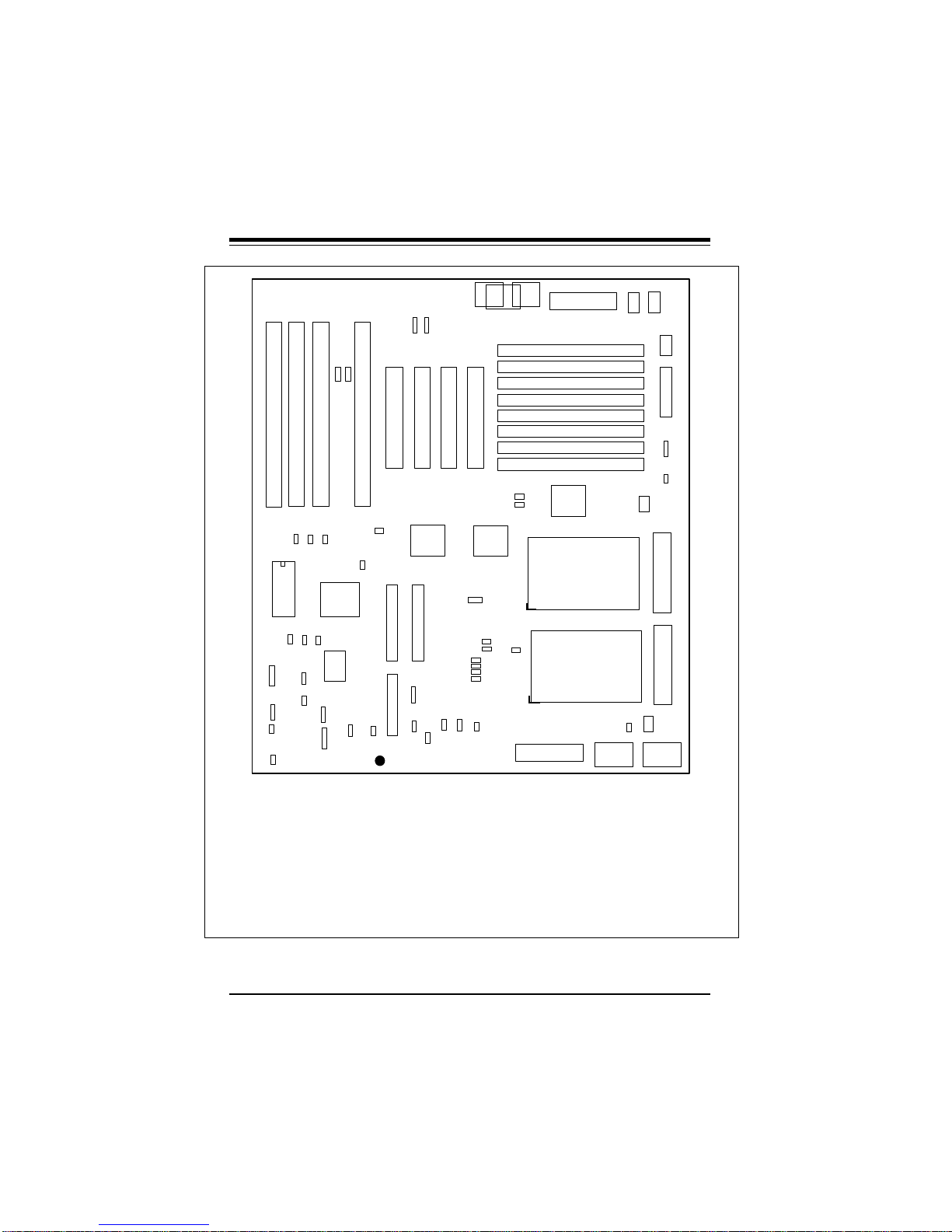
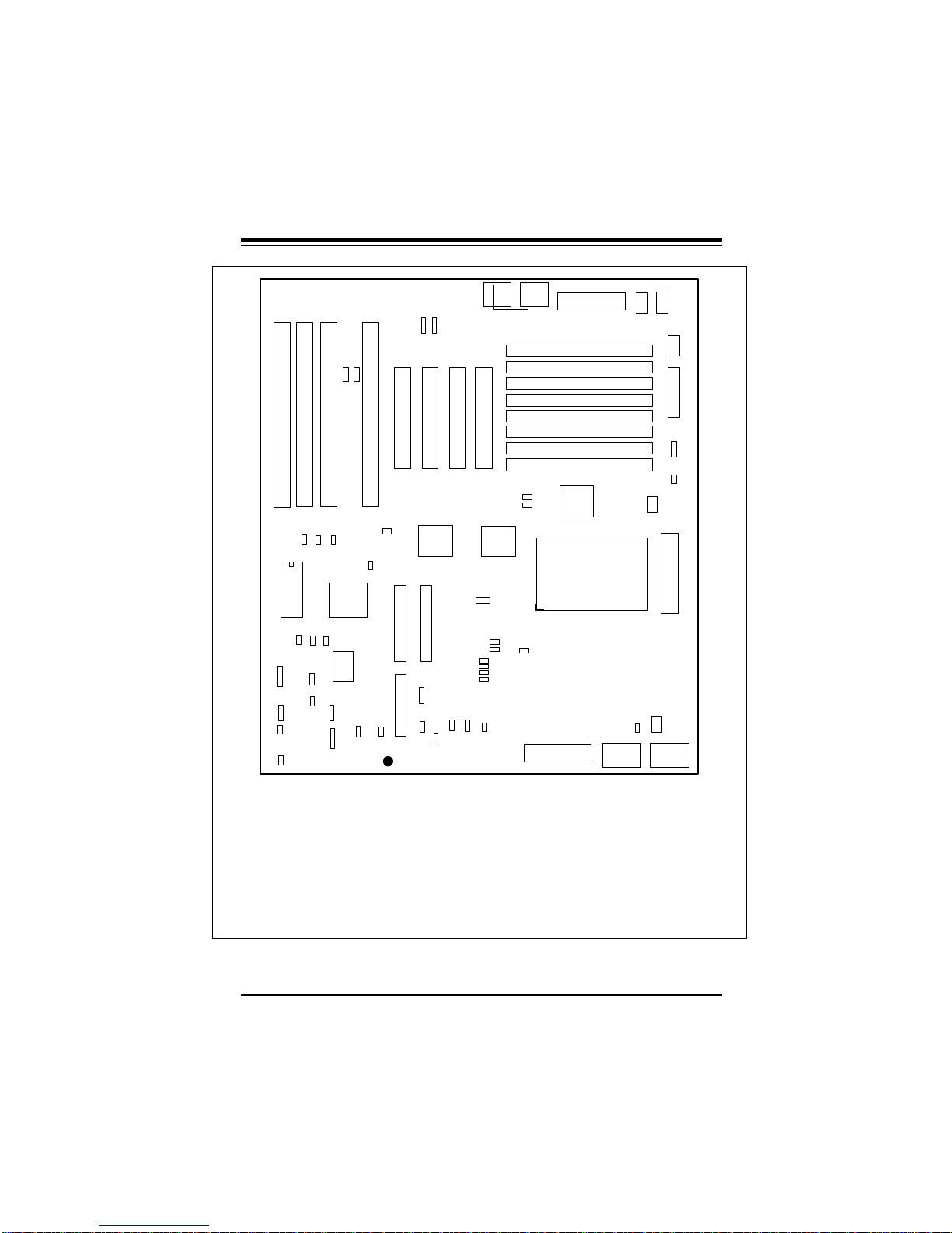
Figure 1-1 shows the layout of the SUPER P6DNF motherboard.
Figure 1-2 shows the layout of the SUPER P6SNF motherboard.
Figure 1-3 shows the architecture of the SUPER P6DNF/P6SNF
motherboard.
1-3
SUPER P6DNF/P6SNF User’s Manual
J28 J31 J29
U834
JP20
KEYLOCK
1
J22
SPEAKER
1
1
JP21
RESET
1
BIOS
J829
1
JP39
SMI SW
1 1
JP880
J828
1
1
JP38
1
JP96
IR CON
J32
J88 J86
11
J832 J833 J831
1
J830
1
U831
J827
1
BT1
BATTERY
+
JP97
1
JP89
ALARM
JP88
1
1
SUPER
JP42
1
J37 J38
J12 J11
1
IDE 2
J85
1
HD LED
FLOPPY
JP95
®
P6DNF
1 1
USB2
1
1
1
J23
J35 J36
U13
IDE 1
JP91
1
USB1
JP921 JP93
J20
5V POWER
Bank3
Bank3
Bank2
Bank2
Bank1
Bank1
Bank0
Bank0
U6
U33
J39
J82
PS/2
MOUSE
J40
J81 AT KB
U5
J83
PS/2 KB
1
JP27
1
JP26
CPU 1
JP15
1
JP36
JP37
1
1
1
1
1
1
JP32
JP31
JP30
JP29
JP90
1
U34
1
JP13
1
1
CPU 2
1
J21
3V POWER
J818
1
JP23
COM1
JP35
JP34
J824
1
VRM
1
VRM
2
COM2
J84
PS/2
MOUSE
1
J817
1
PARALLEL
JP881
Ext Battery
JP22
1
11
VR4VR3
——–——— Manufacturer Settings ——–——
J86: 1-2 JP15: 2-3
J88: 1-2 JP26: OFF
J827: 1-2 JP27: ON
J828 1-2 JP38: OFF
J829: 1-2 JP88: OFF
JP13: 2-3
JP880: 1-2 (default)
2-3 CMOS Clear
JP42: ON (ISA CLK=PCI CLK/4)
OFF (ISA CLK=PCI CLK/3)
——–———————–————––——–——–—
Figure 1-1. SUPER P6DNF Motherboard Layout
—–—–—–——CPU Speed—––—–————
150 166 180 200
JP29 OFF OFF ON ON
JP30 ON ON OFF OFF
JP31 ON ON ON ON
JP32 ON ON ON ON
JP36 ON OFF ON OFF
JP37 OFF ON OFF ON
——–—–——————————–—————
1-4
Chapter 1: Introduction
J28 J31 J29
U834
JP20
KEYLOCK
1
J22
SPEAKER
1
1
JP21
RESET
1
J88 J86
11
J832 J833 J831
1 1
1
J828
1
JP880
1
JP38
1
JP96
IR CON
J827
1
JP97
1
U831
BT1
+
JP89
ALARM
1
1
BIOS
J829
1
JP39
SMI SW
SUPER P6SNF
J32
J830
1
BATTERY
JP88
JP42
1
J37 J38
J12 J11
1
IDE 2
J85
1
HD LED
FLOPPY
JP95
®
1 1
USB2
1
1
1
J23
J35 J36
U13
IDE 1
JP91
1
USB1
JP921 JP93
1
J39
J82
PS/2
MOUSE
J40
JP15
1
JP36
JP37
1
1
1
1
1
J81 AT KB
U5
JP32
JP31
JP30
JP29
JP90
J20
5V POWER
J83
PS/2 KB
Bank3
Bank3
Bank2
Bank2
Bank1
Bank1
Bank0
Bank0
U6
1
JP27
1
JP26
U33
CPU 1
1
1
JP13
1
1
J21
3V POWER
J818
1
JP23
COM1
JP35
JP34
J824
COM2
1
JP881
Ext Battery
1
VRM
1
J84
PS/2
MOUSE
1
J817
1
PARALLEL
JP22
11
VR4VR3
——–——— Manufacturer Settings ——–——
J86: 1-2 JP15: 2-3
J88: 1-2 JP26: OFF
J827: 1-2 JP27: ON
J828 1-2 JP38: OFF
J829: 1-2 JP88: OFF
JP13: 2-3
JP880: 1-2 (default)
2-3 CMOS Clear
JP42: ON (ISA CLK=PCI CLK/4)
OFF (ISA CLK=PCI CLK/3)
——–———————–————––——–——–—
Figure 1-2. SUPER P6SNF Motherboard Layout
—–—–—–——CPU Speed—––—–————
150 166 180 200
JP29 OFF OFF ON ON
JP30 ON ON OFF OFF
JP31 ON ON ON ON
JP32 ON ON ON ON
JP36 ON OFF ON OFF
JP37 OFF ON OFF ON
——–—–——————————–—————
1-5

SUPER P6DNF/P6SNF User’s Manual
PCI
Bus
PCI
CPU 1
with 256/512KB
L2 cache
CPU 2 (P6DNF)
with 256/512KB
L2 cache
1 GB DRAM
FPM or EDO
Intel
440FX
Chipset
PCI
PCI
PCI
ISA
ISA
ISA
ISA
ISA
Bus
Figure 1-3. P6DNF/P6SNF System Board Architecture
1-6

Chapter 1: Introduction
Features
The following list covers the general features of the SUPER P6DNF/
P6SNF motherboard.
CPU
• (SUPER P6DNF) Dual Pentium Pro 200/180/166/150 and >200
MHz processors with integrated 256 or 512KB non-blocking
secondary cache
• (SUPER P6SNF) Single Pentium Pro 200/180/166/150 and >200
MHz processors with integrated 256 or 512KB non-blocking
secondary cache
• 16KB internal cache
• 387-pin ZIF (Zero Insertion Force) socket 8
Bus Speed
• 66/60 MHz external bus with 64-bit data plus 8 bits ECC
Memory
• 64-bit wide data bus of up to 1GB
• Supports 1 MB, 2 MB, 4 MB, 8MB, 16MB and 32MB (x32 or x36
60ns, 72-pin) Fast Page DRAM or EDO
• Error Checking and Correction and Parity Checking support
Dimensions
• Full AT size
• 13.8" x 12"
IDE support
• Integrated IDE controller provides two IDE interfaces for hard
disk(s) and/or CD ROM(s)
• Supports Mode 4
Super I/O
• Supports EPP (Enhanced Parallel Port) and ECP (Extended
Capabilities Port) parallel port, floppy interface and 2 Fast
UART 16550 serial ports
1-7

SUPER P6DNF/P6SNF User’s Manual
Expansion
• Four 16-bit ISA slots
• Four 32-bit PCI slots
BIOS
• AMI® Flash BIOS with built-in setup
• Plug and Play (PnP) with boot block support
Software Compatibility
• 100% IBM® PC/AT® compatible
• DOS, OS/2, SCO UNIX® Open Server, XENIX®, Novell® SMP,
Windows™, Windows NT™ and Windows™ 95
Testing
• 50°C, 48-hour, dynamic burn-in with system-level testing
Manufacturing and Support
• Made in U.S.A.
• Design-level Technical Support and Service in U.S.A.
1-8

Chapter 1: Introduction
1-2 Power Supply
As with all computer products, a stable power source is necessary
for proper and reliable operation. It is even more important for high
CPU clock rates like 200, 180, 166, 150 MHz and future Pentium
Pro processors for the SUPER P6DNF/P6SNF system board.
The SUPER P6DNF/P6SNF can accomodate 5V power supplies.
Although most power supplies generally meet the specifications required by the CPU, some power supplies are not adequate. To
obtain the highest system reliability, be certain that your power supply provides +5 VDC with a voltage range between +4.95 VDC (minimum) and +5.25 VDC (maximum).
It is highly recommended that you use a high quality power supply.
Additionally, in areas where noisy power transmission is present,
you may choose to install a line filter to separate noise from the
computer. You can also install a power surge protector to help
avoid problems caused by power surges.
1-3 Chipset Overview
The Intel 440FX chipset is a high-performance PCIset that supports
full symmetric multi-processor protocol for up to two processors. It
is compliant to the PCI Rev. 2.1 specification. The memory controller provides capability for auto-detection of EDO/FPM DRAM type
installed in the system. It also provides data integrity features including ECC in the memory array and parity error detection. Memory
is upgradable up to 1GB for the SUPER P6DNF/P6SNF.
1-9

SUPER P6DNF/P6SNF User’s Manual
1-4 National Semiconductor Super I/O Controller
The National Semiconductor 87306 Super I/O Controller incorporates an IDE control logic, two full function serial ports, an IEEE
1284 parallel port, industry standard floppy disk controller with 16
byte FIFO, Real Time Clock and an 8042 compatible keyboard controller all in one chip.
The IDE interfaces provide up to Mode 4 support. The two serial
ports are software compatible with the Fast UART 16550. The parallel port is EPP (Enhanced Parallel Port) and ECP (Extended Capabilities Port) compatible, including level 2 support. It includes a
protection circuit against damage caused when the printer is powered up. EPP mode provides for greater throughput than Compatible or Extended modes by supporting faster transfer rates and a
mechanism that allows the host to address peripheral device registers directly. Faster transfers are achieved by automatically generating the address and data strobes. EPP is compatible with both
Compatible and Extended mode parallel-port devices.
1-5 Voltage Regulator Modules (VRM)
The Voltage Regulator Module (VRM1 and VRM2) is a DC-to-DC
converter with a standardized interface to the system. The standardization allows a variety of Voltage Regulator Modules to support
the Pentium Pro processor family and to provide a cost effective
support for CPU upgrade.
1-10

Chapter 1: Introduction
1-6 System Overheat Thermal Control
A back-up cooling fan can be hooked up to JP91, JP92 or JP93. If
the power supply fan or the processor cooling fan goes down, the
circuitry will detect an overheat temperature depending on the user
setting. It will then trigger the backup cooling fan or alarm. The
alarm can be turned on or off using JP88. JP90 is used to connect
the overheat LED. The user can set the temperature range using
JP95. A buzzer can also be connected on JP89 that will sound off
that it is time to replace the power supply fan or the CPU cooling
fan. It is important that the back-up cooling fan be installed correctly in such a way that it will not only cool down the processor but
the whole system as well.
1-11

SUPER P6DNF/P6SNF User’s Manual
1-7 Warranty, Technical Support, and Service
The manufacturer will repair or exchange any unit or parts free of
charge due to manufacturing defects for one year (12 months) from
the original invoice date of purchase.
Parts
Defective parts will be exchanged or repaired within one year (12
months) from the manufacturer’s original invoice purchase date.
BIOS
The manufacturer will exchange the BIOS free of charge (shipping
and handling excluded) due to existing incompatibility issues within
one year from the manufacturer’s original invoice purchase date.
Labor
Mail-in or carry-in service is available for one year (12 months) from
the manufacturer’s original invoice purchase date.
Returns
If you must return products for any reason, refer to Chapter 3 in this
manual, “Returning Merchandise for Service.”
1-12

Chapter 2: Installation
Chapter 2
Installation
2-1 SUPER P6DNF/P6SNF System Components
The equipment listed in this section is required to build a high performance system based on the SUPER P6DNF/P6SNF motherboard. The minimum configuration for a standard system is listed
below. To create the full enhanced configuration, add the enhanced
system configuration equipment listed on the next page to the
equipment listed below.
Standard System Configuration
• 300 watt (minimum) 5V power supply for SUPER P6DNF
• 250 watt (minimum) 5V power supply for SUPER P6SNF
• Chassis with a speaker connected to a 4-pin connector, a push
button switch with 2-pin connector for the reset function, and a
keylock connected to a 5-pin connector
• SUPER P6DNF/P6SNF system board
• AT-compatible keyboard (84 or 101 style keyboard)
• 8 MB or 16 MB of system memory
• One 1.2 MB 5.25" and/or one 1.44 MB 3.5" floppy disk drive
• Use PCI Fast SCSI card and hard disk drive or the on-board
IDE interface
• PCI VGA card
2-1

SUPER P6DNF/P6SNF User’s Manual
Enhanced System Configuration
• Tape drive (for backups)
• Sound card
• Modem/FAX card
• CD-ROM drive
• Add SIMM modules for 32 MB, 64 MB, or 128 MB of system
memory
• Use one or two PCI Ultra Wide Fast SCSI cards
• Use up to four PCI Fast Network cards
2-2 Static-Sensitive Devices
Static-sensitive electric discharge can damage electronic components. To prevent damage to your system board, it is important
to handle it very carefully. The following measures are generally
sufficient to protect your equipment from static discharge.
Precautions
• Use a grounded wrist strap designed for static discharge.
• Touch a grounded metal object before you remove the board
from the anti-static bag.
• Handle the board by its edges only; do not touch its
components, peripheral chips, memory modules, or gold
contacts.
• When handling chips or modules, avoid touching their pins.
• Put the system board and peripherals back into their anti-static
bags when not in use.
• Be sure your computer system’s chassis allows excellent
conductive contacts between its power supply, case, mounting
fasteners, and the system board for grounding purposes.
2-2

Chapter 2: Installation
Unpacking
The system board is shipped in anti-static packaging to avoid static
damage. When unpacking the board, be sure the person handling
the board is static-protected.
2-3 Configuring System Board Jumpers
Use the following settings to configure your system board. Refer to
Figure 1-1 or Figure 1-2 for an illustration of the jumpers. Manufacturing jumpers are permanently fixed or preset in place on the system board. You cannot move them. These jumpers are labeled on
the system board and are listed below as Manufacturer Settings.
Manufacturer Settings
J86: 1-2
J88: 1-2
J827: 1-2
J828 1-2
J829: 1-2
JP13: 2-3
JP15: 2-3
JP26: OFF
JP27: ON
JP38: OFF
JP88: OFF
JP880: 1-2 Default
2-3 CMOS Clear
JP42: ON (ISA CLK=PCI CLK/4)
OFF (ISA CLK=PCI CLK/3)
2-3

SUPER P6DNF/P6SNF User’s Manual
Changing the CPU Speed
The SUPER P6DNF/P6SNF motherboard supports Intel Pentium
Pro 200/180/166/150 MHz and future Pentium Pro processors. For
SUPER P6DNF, both CPU1 and CPU2 have to be the same speed.
To change the CPU speed, change the jumpers shown below on
Table 2-1:
Table 2-1. CPU Speed Selection
150 166 180 200
JP29 OFF OFF ON ON
JP30 ON ON OFF OFF
JP31 ON ON ON ON
JP32 ON ON ON ON
JP36 ON OFF ON OFF
JP37 OFF ON OFF ON
2-4 Mounting the Motherboard in the Chassis
The motherboard has eight standard mounting holes to fit all different types of chassis. Chassis may come with a variety of mounting
fasteners, made of metal or plastic. Although a chassis may have
both metal and plastic fasteners, metal fasteners are the most
highly recommended because they ground the system board to the
chassis. Therefore, use as many metal fasteners as possible for
better grounding.
®
2-5 Connecting Cables
After you have securely mounted the motherboard to the chassis,
you are ready to connect the cables.
2-4
Chapter 2: Installation
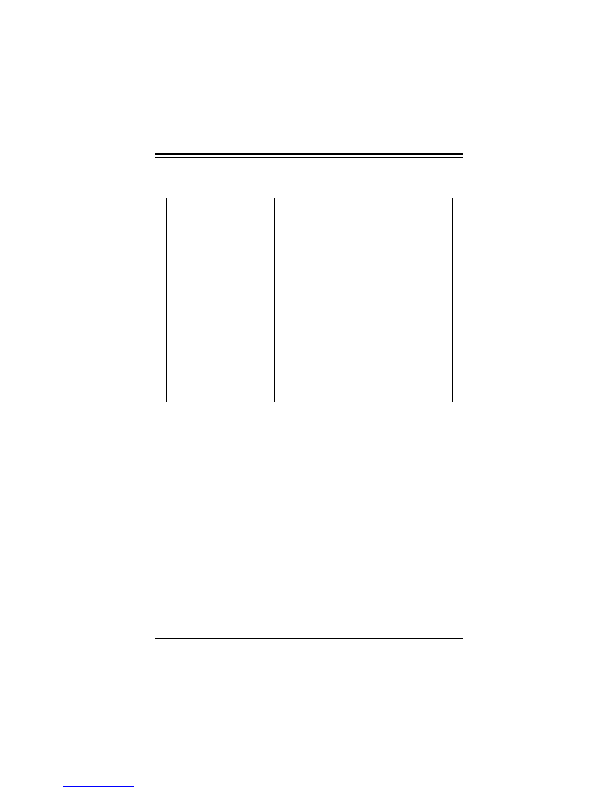
Table 2-2. 5V Power Supply Connector Pin Definitions
Connector Pin
Number Number Function
J20 1 Power Good (Power on reset, TTL signal)
2 +5 VCC
3 +12 VCC
4 -12 VCC
5 Ground (Black wire to be connected)
6 Ground (Black wire to be connected)
7 Ground (Black wire to be connected)
8 Ground (Black wire to be connected)
9 -5 VCC
10 +5 VCC
11 +5 VCC
12 +5 VCC
Power Supply Connectors
Attach power supply cables to J20 for a 5V power supply or J21 for
a 3.3V power supply (optional for OEM customers only). Do not
force the cables, but make sure they are fully seated. The two black
wires on each power cable sit next to each other when correctly
installed. See Table 2-2 for pin definitions of a 5V power supply.
See Table 2-3 for pin definitions of a 3.3V power supply.
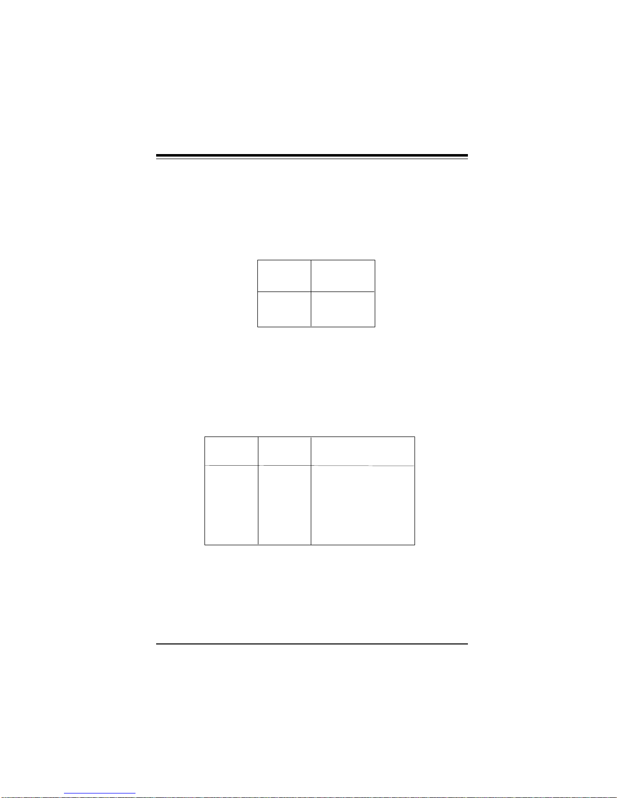
Turbo Function
There are no jumpers for turbo switch and turbo LED. By default,
SUPER P6DNF/P6SNF is in turbo mode.
2-5

SUPER P6DNF/P6SNF User’s Manual
Table 2-3. 3.3V Power Supply Connector Pin Definitions
(Optional for OEM customers only)
Connector Pin
Number Number Function
J21 1 Ground (Black wire to be connected)
2 Ground (Black wire to be connected)
3 Ground (Black wire to be connected)
4 +3.3 VCC
5 +3.3 VCC
6 +3.3 VCC
7 +3.3 VCC
8 +3.3 VCC
9 +3.3 VCC
10 Ground (Black wire to be connected)
11 Ground (Black wire to be connected)
12 Ground (Black wire to be connected)
Note:
The +3.3V power supply is for 3.3V PCI add-on cards or CPU power
support when 3.3V CPU is used.
2-6
Chapter 2: Installation
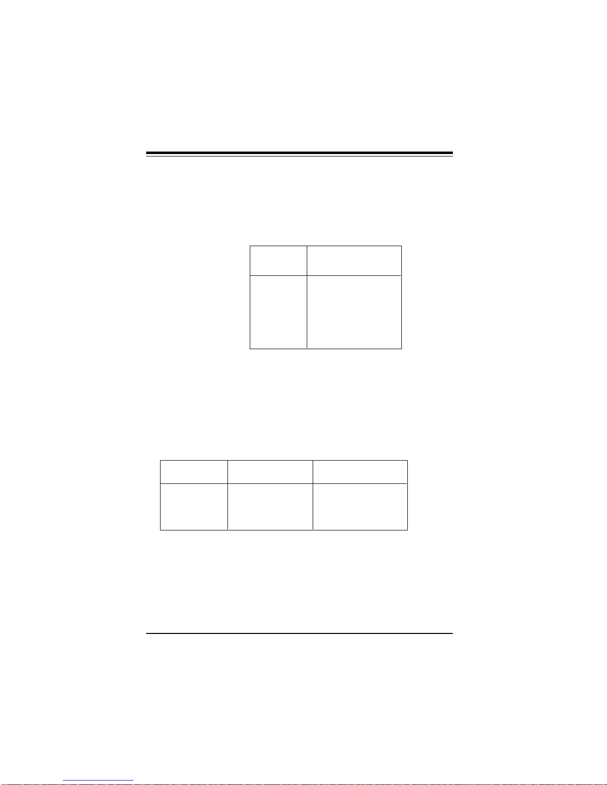
Reset Cable Connector
The reset cable connector JP21 has two pins. The
connector attaches to the hardware Reset switch on the computer
case. See Table 2-4 for pin definitions
Table 2-4. Reset Pin Definitions
Pin
Number Definition
1 Reset
2 Ground
Keylock/Power LED Cable Connector
The keylock/power LED cable connector JP20 has five pins. See
Table 2-5 for pin definitions.
Table 2-5. Keylock/Power LED Pin Definitions
Pin
Number Function Definition
1 + Red wire, LED power
2 Key No connection
3 GND Black wire
4 Keyboard inhibit
5 GND Black wire
2-7
SUPER P6DNF/P6SNF User’s Manual
Keyboard Connector
The keyboard connector J81 has five pins. See Table 2-6 for pin
definitions.
Table 2-6. Keyboard Connector Pin Definitions
Pin
Number Function
1 Keyboard clock
2 Keyboard data
3 Spare
4 Ground
5 +5 VDC
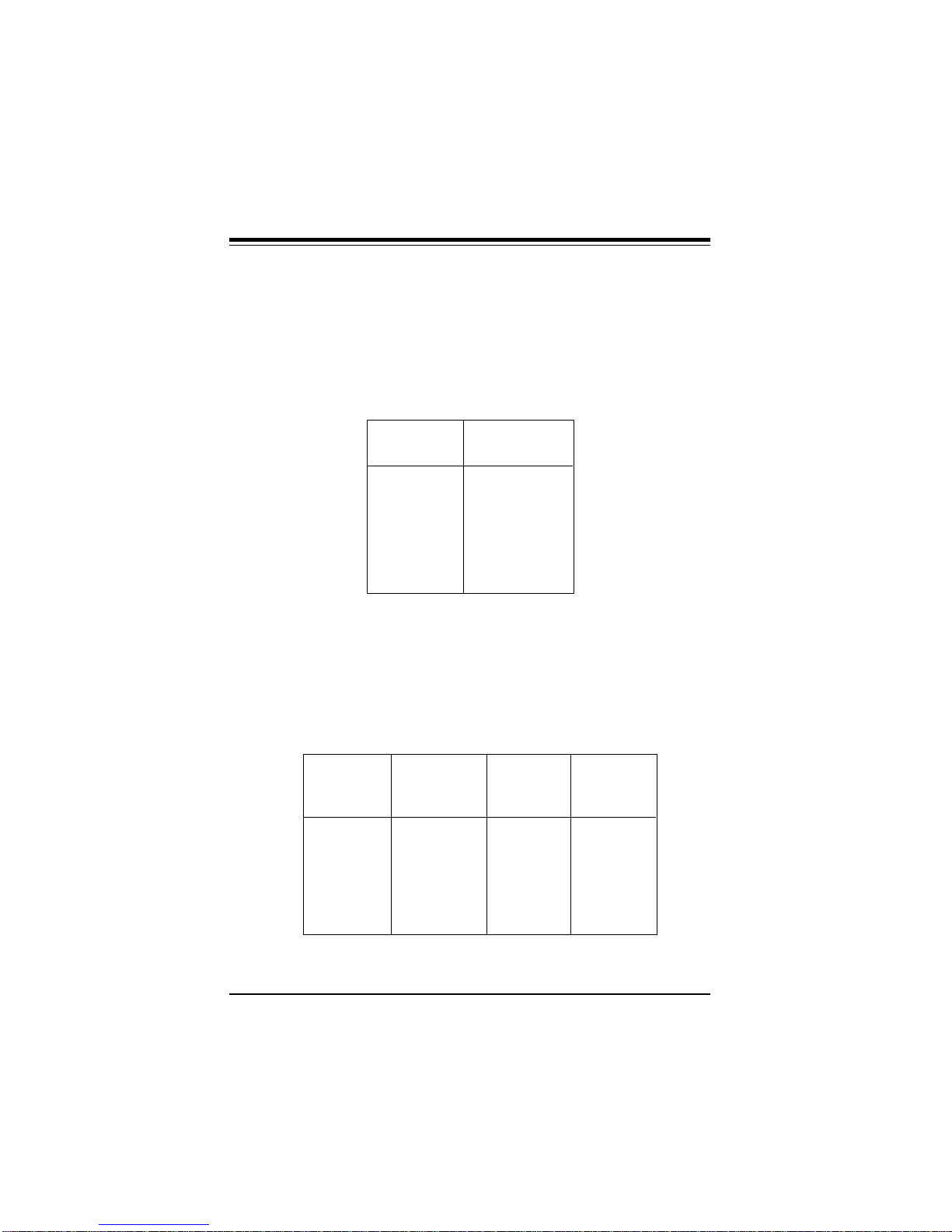
Thermal Control Connector
Use the settings on Table 2-7 to set the system temperature condition for JP95. Once the temperature cools down, the back-up fan
will automatically shut down.
Table 2-7. Thermal Control Connector
Setting Turn on (°°C) Shut down (°°C)
1-2 55 51
2-3 62 58
OFF 69 65
2-8

Chapter 2: Installation
Hard Drive LED
The hard drive LED J23 has four pins. See Table 2-8 for pin definitions.
Table 2-8. Hard Drive LED Pin Definitions
Pin
Number Function
1 Pull_Up_330
2 Key
3 HD Active
4 Pull_Up_330
Speaker Cable Connector
The speaker cable connector J22 has four pins. See Table 2-9 for
pin definitions.
Table 2-9. Speaker Connector Pin Definitions
Pin
Number Function Definition
1 + Red wire, speaker data
2 Key No connection
3 VCC Speaker data
4 GND Black wire
2-9
SUPER P6DNF/P6SNF User’s Manual
PS/2 Keyboard and Mouse Ports
The PS/2 keyboard is located on J83 and the PS/2 mouse is located
on J82 and J84. The cable for J84 can be obtained from the manufacturer. See Table 2-10 for pin definitions.
Table 2-10. PS/2 Keyboard and Mouse Pin Definitions
(J82 and J83 Optional for OEM customers only)
Pin
Number Function
1 Data
2 NC
3 Ground
4 VCC
5 Clock
6 NC
Serial Ports
Serial port COM1 is located on J818 and serial port COM2 is
located on J824. See Table 2-11 for pin definitions.
Table 2-11. Serial Ports Pin Definitions
Pin Pin
Number Function Number Function
1 DCD 6 CTS
2 DSR 7 DTR
3 Serial In 8 RI
4 RTS 9 GND
5 Serial Out 10 NC
2-10
 Loading...