


SUPER
SUPER P6DGH
USER’S AND BIOS
®
MANUAL
Revision 1.0

The information in this User’s Manual has been carefully reviewed and is believed to be
accurate. The vendor assumes no responsibility for any inaccuracies that may be
contained in this document, makes no commitment to update or to keep current the
information in this manual, or to notify any person or organization of the updates.
SUPERMICRO COMPUTER reserves the right to make changes to the product described in
this manual at any time and without notice. This product, including software, if any, and
the documentation may not, in whole or in part, be copied, photocopied, reproduced,
translated or reduced to any medium or machine without prior written consent.
IN NO EVENT WILL SUPERMICRO COMPUTER BE LIABLE FOR DIRECT, INDIRECT,
SPECIAL, INCIDENTAL OR CONSEQUENTIAL DAMAGES ARISING FROM THE USE OR
INABILITY TO USE THIS PRODUCT OR DOCUMENTATION, EVEN IF ADVISED OF THE
POSSIBILITY OF SUCH DAMAGES. IN PARTICULAR, THE VENDOR SHALL NOT HAVE
LIABILITY FOR ANY HARDWARE, SOFTWARE OR DATA STORED OR USED WITH THE
PRODUCT, INCLUDING THE COSTS OF REPAIRING, REPLACING, INTEGRATING,
INSTALLING OR RECOVERING SUCH HARDWARE, SOFTWARE OR DATA.
Unless you request and receive written permission from SUPERMICRO COMPUTER, you
may not copy any part of this document.
Information in this document is subject to change without notice. Other products and
companies referred to herein are trademarks or registered trademarks of their respective
companies or mark holders.
Copyright © 1998 by SUPERMICRO COMPUTER INC.
All rights reserved.
Printed in the United States of America.

Preface
About This Manual
This manual is written for system houses, experienced PC technicians and knowledgeable PC end users. It provides information for
the installation and use of the SUPER P6DGH motherboard. The
SUPER P6DGH supports Pentium II 233-450 MHz Slot 1 processors.
The Pentium II processor with Dual Independent Bus Architecture is
housed in a new packaging technology called the Single Edge Contact Cartridge (S.E.C.C.). This new cartridge package and its associated "Slot 1" infrastructure will provide the headroom for future
high-performance processors.
Manual Organization
Chapter 1, Introduction, describes the features, specifications and
performance of the SUPER P6DGH system board, provides detailed
information about the chipset, and offers warranty information.
Preface
Refer to Chapter 2, Installation, for instructions on how to install the
Pentium II processor, the retention mechanism and the heat sink
support. This chapter also provides you with instructions for handling static-sensitive devices. Read this chapter when you want to
install or remove SIMM/DIMM memory modules and to mount the
system board in the chassis. Also refer to this chapter to connect
the floppy and hard disk drives, IDE interfaces, and the parallel and
serial ports as well as the cables for the power supply, the reset
cable, the Keylock/Power LED, the speaker and the keyboard.
iii

SUPER P6DGH User’s Manual
If you encounter any problems, please see Chapter 3, Troubleshooting, which describes troubleshooting procedures for the video,
the memory and the setup configuration stored in memory. Instructions are also included for contacting a technical assistance support representative, returning merchandise for service and visiting
our website for BIOS upgrades.
See Chapter 4 for configuration data and the AMIBIOS features.
Chapter 5 covers the WinBIOS setup options.
iv

Table of Contents
Table of Contents
Preface
About This Manual ......................................................................................... iii
Manual Organization...................................................................................... iii
Quick Reference Guide................................................................................. ix
Chapter 1: Introduction
1-1 Overview............................................................................................... 1-1
SUPER P6DGH Image................................................................ 1-4
SUPER P6DGH Motherboard Layout ....................................... 1-5
SUPER P6DGH Features ........................................................... 1-6
1-2 PC Health Monitoring ........................................................................ 1-8
1-3 ACPI/PC 98 Features ...................................................................... 1-11
1-4 Chipset Overview.............................................................................. 1-12
1-5 Wake-On-LAN .................................................................................... 1-13
1-6 Power Supply .................................................................................... 1-13
1-7 Winbond Super I/O Controller ........................................................ 1-14
1-8 AIC-7896 SCSI Controller ................................................................ 1-15
1-9 Warranty, Technical Support and Service ................................... 1-16
Parts.............................................................................................. 1-16
BIOS .............................................................................................. 1-16
Labor............................................................................................. 1-16
Returns......................................................................................... 1-16
Chapter 2: Installation
2-1 Pentium II Processor Installation ................................................... 2-1
OEM Pentium II and Heat Sink Support.................................. 2-5
Removing the Pentium II Processor........................................ 2-7
2-2 Static-Sensitive Devices ................................................................... 2-8
Precautions ................................................................................... 2-8
v

SUPER P6DGH User’s Manual
Unpacking...................................................................................... 2-8
2-3 Changing the CPU Speed ............................................................... 2-8
2-4 Mounting the Motherboard in the Chassis ................................. 2-10
2-5 Connecting Cables and Jumpers ................................................ 2-10
Power Supply Connectors........................................................ 2-11
PW_ON Connector ...................................................................... 2-13
Infrared Connector ...................................................................... 2-13
Reset Header.............................................................................. 2-14
Keylock/Power LED Connector ............................................... 2-14
Hard Drive LED .......................................................................... 2-15
Speaker Connector .................................................................... 2-15
AT Keyboard Connector ............................................................ 2-16
Universal Serial Bus .................................................................. 2-16
PS/2 Mouse Header ................................................................... 2-17
Serial Ports.................................................................................. 2-17
Power On/Off State .................................................................... 2-18
CMOS Clear................................................................................. 2-18
Overheat LED .............................................................................. 2-19
Buzzer Overheat Notification .................................................... 2-19
Chassis Intrusion Connector .................................................. 2-19
Wake-On-LAN .............................................................................. 2-20
Fan Connectors.......................................................................... 2-20
i960 Serial Port ........................................................................... 2-21
i960 Fail LED Indicator ............................................................. 2-21
i960 Initialization Modes........................................................... 2-22
i960 Jumper Settings ................................................................ 2-22
I2C Connector .............................................................................. 2-23
SLED (SCSI LED) Indicator ..................................................... 2-23
I2O Debug LED (Optional) ........................................................ 2-24
AT/ATX Power Mode Jumper Settings ................................... 2-24
SCSI Termination Jumper Settings ....................................... 2-25
vi

Table of Contents
SBLINK Connector ..................................................................... 2-26
2-6 Installing/Removing SIMM/DIMM Modules .................................. 2-27
SIMM/DIMM Module Installation ............................................... 2-29
Removing DIMM Modules ......................................................... 2-29
Removing SIMM Modules ......................................................... 2-29
2-7 Connecting Parallel, FDD and HDD ............................................ 2-30
Parallel Port Connector ............................................................ 2-31
Floppy Connector ....................................................................... 2-32
IDE Interfaces ............................................................................. 2-33
AGP Port Interface ...................................................................... 2-34
ULTRA II LVD SCSI Interfaces ................................................ 2-35
Wide SCSI Interface .................................................................. 2-36
Chapter 3: Troubleshooting
3-1 Troubleshooting Procedures ........................................................... 3-1
Before Power On .......................................................................... 3-1
Troubleshooting Flowchart ........................................................ 3-1
No Power ........................................................................................ 3-2
No Video ........................................................................................ 3-2
Memory Errors............................................................................... 3-2
Losing the System's Setup Configuration .............................. 3-7
3-2 Technical Support Procedures ........................................................ 3-3
3-3 Frequently Asked Questions............................................................ 3-4
3-4 Returning Merchandise for Service................................................ 3-7
Chapter 4: AMIBIOS
4-1 Introduction .......................................................................................... 4-1
4-2 BIOS Features ..................................................................................... 4-2
BIOS Configuration Summary Screen ..................................... 4-3
AMIBIOS Setup .............................................................................. 4-3
vii

SUPER P6DGH User's Manual
Chapter 5: Running Setup
5-1 Setup ..................................................................................................... 5-1
Standard Setup ............................................................................. 5-1
Advanced Setup ............................................................................ 5-3
Chipset Setup ............................................................................... 5-7
Power Management ................................................................... 5-13
PCI/PnP Setup ............................................................................ 5-15
Peripheral Setup......................................................................... 5-18
5-2 Security Setup ................................................................................... 5-21
5-3 Utility Setup ........................................................................................ 5-22
Anti-Virus ...................................................................................... 5-22
Language..................................................................................... 5-22
5-4 Default Settings ................................................................................ 5-22
Optimal Default........................................................................... 5-22
Fail-Safe Default......................................................................... 5-22
Appendices:
Appendix A: BIOS Error Beep Codes and Messages ......................... A-1
Appendix B: AMIBIOS Post Diagnostic Error Messages .................... B-1
viii

Quick Reference Guide
Quick Reference Guide
Jumper Function Page
BZ_ON Buzzer Enable/Disable 2-18
JA5, JA6, JA7 SCSI Terminations 2-24
JB1, JB2, JB3, JB4 CPU Speed Selection 2-8
JBT1 CMOS Clear 2-17
JP11 External Bus Speed 2-8
JP20 ATX Power On/Off State 2-17
JP911 i960 Jumper 2-21
JP915 i960 Initialization Mode 2-21
JP917 i960 Jumper 2-21
JP918 i960 Reset Mode 2-21
JP919 i960 Retry Mode 2-21
JP920 i960 Disable Mode 2-21
JP921 i960 BIST Mode 2-21
JP924 i960 Jumper 2-21
Connector Function Page
AGP AGP Port 2-33
ID4 i960 Fail LED 2-20
J15, J16 IDE Interfaces 2-32
J17, J18 USB 2-15
J19 Parallel Port 2-30
J22 Floppy Connector 2-31
J36 (PWR_SEC) Secondary ATX Pwr Connector 2-11
J74 AT Keyboard 2-15
J940 I2C Connector 2-22
J943 i960 Serial Port 2-20
JF1 Hard Drive LED 2-14
JF1 Keylock/Power LED 2-13
JF1 Speaker 2-14
ix

SUPER P6DGH User's Manual
Connector Function Page
JF2 IR Connector 2-12
JF2 ATX PW_ON 2-12
JF2 Reset Header 2-13
JL1 Chassis Intrusion 2-18
JOH1 Overheat LED 2-18
JP20, JP21 COM 1, COM 2 2-16
JP25 PS/2 Mouse Header 2-16
JT1, JT2 CPU1, CPU2 Fans 2-19
JT3 Thermal/Overheat Fan 2-19
PW1 Main AT Power Connector 2-10
PW2 Main ATX Power Connector 2-11
PW5 Secondary AT Pwr Connector 2-10
WOL Wake-On-LAN 2-19
x

Chapter 1: Introduction
Chapter 1
Introduction
1-1 Overview
The SUPER P6DGH supports dual Pentium II 233-450 MHz processors. This motherboard is based on Intel’s 440GX chipset, which
enables a 100 MHz system bus speed, an Accelerated Graphics
Port (AGP), Wake-on-LAN, SDRAM, concurrent PCI and an Ultra
DMA 33 MB/s burst data transfer rate. In addition, the SUPER
P6DGH is I2O−ready with a built-in 66MHz Intel i960 RD I/O processor.
The motherboard is Full AT size (13.2" x 12.2"). The SUPER P6DGH
provides 9 PCI slots, 2 ISA slots and an Accelerated Graphics Port.
It can accommodate a total of 2 GB registered DIMM or EDO supported (66Mhz), or 1 GB SDRAM memory with 4 168-pin DIMM sockets.
AGP reduces contention between the CPU and I/O devices by broadening the bandwidth of graphics to memory. It delivers a maximum
of 532 MB/s 2x transfer mode, which is quadruple the PCI speed!
The I2O architecture of the SUPER P6DGH consists of a 66 MHz
i960 RD I/O processor, an 8 Mb Flash I/O BIOS and local IOP
memory (optional) of up to 64 MB in 2 72-pin SIMMS. The I2O architecture provides a standard way to off-load the I/O functions from
the CPU, creating a direct I/O pipeline that no longer passes
through the host processor. Besides delivering increased system
performance, the I2O specification eliminates the need for different
drivers for each combination of operating system and SCSI or Network Interface Card. Because the drivers may be standardized and
not rewritten for new operating system releases, they can become
more highly optimized and robust to improve performance and reliability in mission-critical enterprise computing.
1-1

SUPER P6DGH User’s Manual
To attain portability across multiple operating systems and host
platforms, I2O drivers are divided into the OS Services Module (OSM)
and the Hardware Device Module (HDM). The first module interfaces with the host operating system. The second interfaces with
the particular device, media or server managed by the driver. The
two modules interface with each other through a two-layered communications system. A Message Layer sets up a communications
session and a Transport Layer defines how information will be
shared. The Message Layer resides on the Transport Layer.
The i960 RD I/O processor (IU20) is a highly integrated, intelligent
I/O subsystem on a chip. Mode 3 is the default setting for normal
I2O operation. The i960 RD has two main functions. As a local
processor, it off-loads interrupt-intensive I/O tasks from the host
CPU. Its architecture is composed of a RISC core surrounded by
peripherals essential to the I/O function. The onboard PCI-to-PCI
bridge enables designers to connect I/O components directly to the
PCI bus and to also add additional PCI slots. The bridge improves
overall system performance by reducing bus traffic.
Wake-on-LAN allows for remote network management and configuration of the PC, even in off-hours when the PC is turned off. This
reduces the complexity of managing the network.
Other features that maximize simplicity in managing the computer
are PC 98-ready and support for an Advanced Configuration and
Power Interface (ACPI). With PC Health Monitoring, you can protect
your system from problems before they even occur.
Included in the I/O are 2 EIDE ports, a floppy port, an ECP/EPP
parallel port, a PS/2 mouse port, 2 serial ports (including an infrared port) and 2 USB ports. The SUPER P6DGH has an onboard
Adaptec 7896 dual-channel Ultra II LVD (Low Voltage Device) SCSI
controller with a data transfer rate of up to 80 MB/s. This supports
the Adaptec ARO-1130CA2 RAIDport III card for increased I/O performance and fault tolerance. The boards come with a CD that
includes such software utilities as the SUPERMICRO PIIX4 Upgrade
1-2

Chapter 1: Introduction
Utility for Windows 95, a BIOS Flash Upgrade Utility, a DMI
Browser for Windows 95/98, a DMI Wizard, the SUPERMICRO SUPER Doctor Utility ver 1.31a and Intel's LANDesk Client Manager
for Windows NT and Windows 95/98 (optional).
1-3

SUPER P6DGH User’s Manual
SUPER P6DGH
Figure 1-1. SUPER P6DGH Motherboard Image
1-4
Chapter 1: Introduction
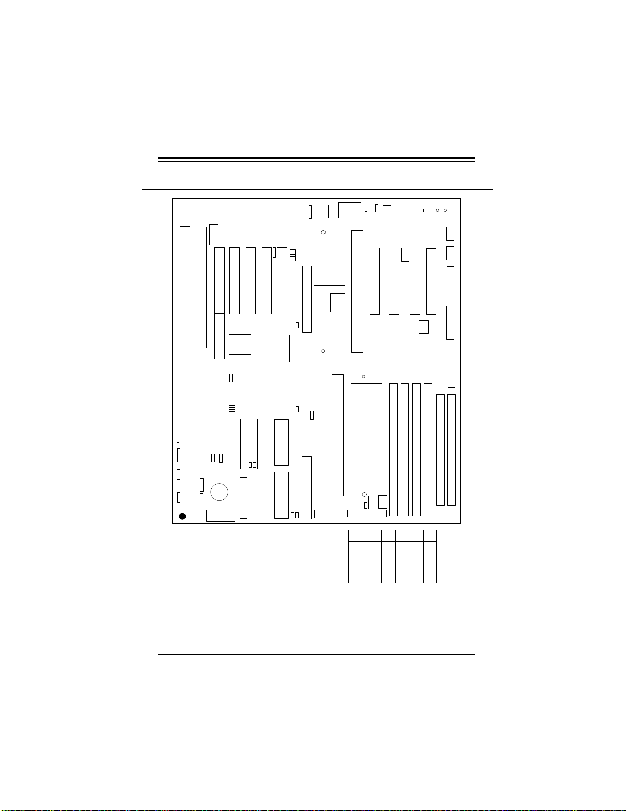
Figure 1-2. P6DGH Motherboard Layout
SBLINK
J14
J13
PCI 2
PCI 3
PCI 1
J9
J10
RAID PORT III
JA4
U38
BIOS
JF2
IR
CON
PW_ON
RESET
JF1
IDE
SLED
LED
KEY
LOCK
SPEAKER
®
——–—— Primary Jumper Settings ————
BZ_ON: ON (default)
JA5: ON
JA6: ON
JA7: ON
JBT1: 1-2 (default)
JL1: OFF (default)
JP11: 1-2 Auto (default)
JP20: 1-2 PIIX4 CTL
JP911: ON
JP917: ON
JP924: 1-2
——–———————–———–——–——–—
WOL
JB4
JB3
JB2
JB1
JBT1 JP20
CMOS
Clear
BT2
+
JL1
-
PWR_SEC
J36
2-3 CMOS Clear
2-3 66 Mhz
OFF 100 Mhz
2-3 Save PD State (default)
PCI 4
J11
J12
* J9 is PCI slave only
U14
PIIX4E
J15
J16
1
1
IDE 1
IDE 2
JA6
JA7
J22
1
BATTERY
FLOPPY
PCI 5
J940
J35
UA1
7896
SCSI
JA1
1
ULTRA II LVD/SE
JA2
1
ULTRA II LVD/SE
JP915
JP918
JP919
JP920
JP921
JP911
JA5
JA3
(CHANNEL A)
1
(CHANNEL B)
JOH1
BZ_ON
USB
JP25
11
1
PS/2
J74 AT KB
MOUSE
J17
J18
IU20
i960 RD
AGP PORT
i960 BIOS
J2
JP11
CPU 2
ULTRA SCSI
JATPWR
CPU Core/
Bus Ratio
i960 Initialization Jumper Defaults (See page 2-21.)
JP915 OFF
JP918 ON (Mode 0)
JP919 ON (Mode 0)
JP920 OFF (Enable 960)
JP921 ON (Disable BIST)
——————–—–——————————————
1
JPWAKE
J1
CPU 1
U2
443GX
JT2
JP100
ATX POWER
PW2
3.0
3.5
4.0
4.5
5.0
5.5
6.0
JT1
JP924
IJ6
IJ7
IJ8 IJ22
1
J943
J4
Bank0
Bank1
JT3
JB1
JB2
JB3
ON
OFF
ON
OFF
OFF
ON
ON
ON
OFF
OFF
ON
OFF
ON
OFF
OFF
OFF
OFF
OFF
ON
ON
ON
J6J7J5
JP917
IU48
Bank2
JB4
ON
ON
ON
ON
ON
ON
OFF
ID4 ID3
+5V EXTRA
PW5
J918
Bank3
i960 MEM
JP21
1
JP20
1
J19
1
PW1
1
POWER
J917
COM2
COM1
PARALLEL
AT POWER
1-5

SUPER P6DGH User’s Manual
SUPER P6DGH Features
The following list covers the general features of the SUPER P6DGH.
CPU
• Dual Pentium II 233-450 MHz processors
I2O-Ready
• 66 MHz i960 RD I/O processor
• Up to 64 MB Local IOP memory
• 8 MB Flash I/O BIOS
Memory
• 2 GB Registered DIMM or EDO, or 1 GB SDRAM
• Error Checking and Correction and Parity Checking support
Chipset
• Intel 440GX
Expansion Slots
• 9 PCI slots
• 2 ISA slots
• 1 AGP slot
BIOS
• 2 MB AMI® Flash BIOS
• DMI 2.0, Plug and Play (PnP)
PC Health Monitoring (781D)
• Seven onboard voltage monitors for CPU cores, +3.3V, ±5V and
±12V
• Three fan-status monitors with firmware/software on/off control
• Chassis temperature monitor and control
• CPU fan auto-off in sleep mode
• System overheat control and alarm
• Chassis intrusion detection
• System resource alert
• Hardware BIOS virus protection
• Switching voltage regulators for the CPU core
• SUPERMICRO SUPER Doctor and Intel LANDesk Client
1-6

Chapter 1: Introduction
Manager (LDCM) support
ACPI/PC 98 Features
• Microsoft OnNow
• Slow blinking LED for sleep-state indicator (ATX power only)
• BIOS support for USB keyboard
• Real-time clock wake-up alarm (ATX power only)
• Main switch override mechanism (ATX power only)
• External modem ring-on (wake-on-ring) (ATX power only)
Onboard I/O
• Two 68-pin 16-bit Ultra II LVD/SE SCSI connectors and one 50pin 8-bit Ultra SCSI connector
• RAIDport for Adaptec ARO-1130CA2 RAIDport III card
• Two EIDE Bus Master interfaces that support Ultra DMA/33 and
Mode 4
• One floppy interface
• Two UART 16550A serial ports
• One parallel port that supports both EPP (Enhanced Parallel
Port) and ECP (Extended Capabilities Port)
• PS/2 mouse port
• Infrared port
• Two USB ports
CD Utilities
• Intel LANDesk Client Manager for Windows NT® and Windows
95 (optional)
• PIIX4 Upgrade Utility for Windows 95
• BIOS Flash Upgrade Utility
• SUPER Doctor Utility
• SCSI Utility, manual and driver
Dimensions
• Full AT size (13.2" x 12.2")
®
1-7

SUPER P6DGH User’s Manual
1-2 PC Health Monitoring
This section describes the PC health monitoring features of the
SUPER P6DGH. It has an onboard Winbond 781D System Hardware Monitor chip that supports PC health monitoring.
Seven Onboard Voltage Monitors for the CPU Cores,
+3.3V, ±±5V, and ±±12V
The onboard voltage monitors scan seven voltages every second.
When running SUPER Doctor or Intel LDCM, once a voltage becomes unstable, a warning or an error message will be reported
on-screen. Users can adjust the threshold of the monitored voltage
to determine the sensitivity of the voltage monitor.
Three Fan-Status Monitors with Firmware/Software On/
Off Control
The PC health monitor can check the RPM status of the cooling
fans. The onboard 3-pin CPU fans are controlled by the ACPI BIOS
and the ACPI-enabled operating system. The thermal fan is controlled by the overheat detection logic.
Chassis Temperature Control
The thermal control sensor monitors the real-time chassis temperature. It will turn on the backup fan whenever the chassis temperature exceeds a user-defined threshold. The overheat circuitry
runs independently from the CPU. It can still monitor for overheat
conditions even if the CPU is in sleep mode. Once it detects that
the chassis temperature is too high, it will automatically turn on the
backup fan and trigger the overheat LED (JOH1) and the overheat
buzzer (BZ_ON). The onboard chassis thermal circuitry can monitor
the overall system temperature and alert users when the chassis
temperature gets too high.
1-8

Chapter 1: Introduction
CPU Fan Auto-Off in Sleep Mode
The CPU fan(s) runs when the power is on, but can be turned off
when the CPU is in sleep mode. When in sleep mode, the CPU
does not run at full power and therefore generates less heat. For
power saving purposes, the user has the option of shutting down
the CPU fan(s) at such times.
System Overheat Alarm and LED
This feature is available when used with SUPERMICRO's SUPER
Doctor Utility. The program will generate a beep sound via the
speaker when it detects a system overheat condition. The overheat
condition can be defined by the user. The program can also give an
on-screen indication when the system overheats.
Chassis Intrusion Detection
The chassis intrusion circuitry can detect unauthorized intrusion to
the system. The chassis intrusion connector is located on JL1.
Attach a microswitch to JL1. When the microswitch is closed, it
means that the chassis has been opened. The circuitry will then
alert the user with a warning message when the system is turned
on. This circuitry uses the onboard battery for power.
System Resource Alert
This feature is available when used with the Intel LANDesk Client
Manager. It is used to notify the user of certain system events. For
example, if the system is running low on virtual memory, there might
not be enough hard drive space to save the data. LDCM will then
alert the user of the potential problem.
1-9

SUPER P6DGH User’s Manual
Hardware BIOS Virus Protection
The system BIOS is protected by hardware so that no virus can
infect the BIOS area. The user can only change the BIOS content
through the flash utility provided by SUPERMICRO. This feature can
prevent viruses from infecting the BIOS area and destroying valuable data.
Switching Voltage Regulator for the CPU Core
The switching voltage regulator for the CPU core can support current up to 20A with the auto-sensing voltage ID ranging from 1.8V to
3.5V. This will allow the regulator to run cooler and thus make the
system more stable.
Intel LANDesk Client Manager (LDCM) Support
As the computer industry grows, PC systems have become more
complex and harder to manage. Historically, only experts have
been able to fully understand and control these complex systems.
Today's users want manageable systems that they can interact with
automatically. Client Manager enables both administrators and clients to:
• Review system inventory
• View DMI-compliant component information
• Back up and restore system configuration files
• Troubleshoot
• Receive notifications of system events
• Transfer files to and from client workstations
• Remotely reboot client workstations
1-10

Chapter 1: Introduction
1-3 ACPI/PC 98 Features
ACPI stands for Advanced Configuration and Power Interface. The
ACPI specification defines a flexible and abstract hardware interface that provides a standard way to integrate power management
features throughout a PC system, which includes its hardware, the
operating system and application software. This enables the system to automatically turn on and off peripherals such as CD-ROMs,
network cards, hard disk drives and printers. This also includes
consumer devices connected to the PC such as VCRs, TVs, telephones and stereos.
In addition to enabling operating system-directed power management, ACPI provides a generic system event mechanism for Plug
and Play and an operating system-independent interface for configuration control. ACPI leverages the Plug and Play BIOS data
structures while providing an architecture-independent processor
implementation that is compatible with both Windows 95 and Windows NT.
Microsoft OnNow
The OnNow design initiative is a comprehensive, system-wide approach to system and device power control. OnNow is a term for a
PC that is always on but appears to be off and that can respond
immediately to user or other requests.
Slow Blinking LED for Sleep-State Indicator
When the CPU goes into a sleep state, the power LED will start
blinking to indicate that the CPU is in sleep mode. When the user
presses any key, the CPU will wake-up and the LED will automatically stop blinking and remain on.
1-11

SUPER P6DGH User’s Manual
BIOS Support for USB Keyboard
If the USB keyboard is the only keyboard in the system. It will work
like a normal keyboard during system boot-up.
Real-Time Clock Wake-up Alarm (ATX power only)
Although the PC is perceived to be off when not in use, it is still
capable of responding to wake-up events according to a scheduled
date and time. The user can set a timer to wake-up or shutdown
the system at some predetermined time.
Main Switch Override Mechanism (ATX power only)
When an ATX power supply is used, the power button can function
as a system suspend button. When the user presses the power
button, the system will enter a SoftOff state. The monitor will be
suspended and the hard drive will spin down. Pressing the power
button again will cause the whole system to wake-up. During the
SoftOff state, the ATX power supply provides power to keep the required system circuitry alive. If the system malfunctions and you
want to turn off the power, just press and hold the power button for
approximately 4 seconds. The power will turn off and enter the
SoftOff state.
External Modem Ring-On (ATX power only)
Wake-up events can be triggered by a device (such as an external
modem ringing) when BIOS enables this function and the system is
in the SoftOff state.
1-4 Chipset Overview
The 440GX chipset developed by Intel is the ultimate processor platform targeted for 3D graphics and multimedia applications. Along
with System-to-PCI bridge integrated with optimized DRAM control-
1-12

Chapter 1: Introduction
ler and data path, the chipset supports the Accelerated Graphics
Port (AGP) interface. AGP is a high performance, component level
interconnect targeted at 3D applications and is based on a set of
performance enhancements to PCI. The I/O subsystem portion of
the 440GX platform is based on the PIIX4, a highly integrated version of Intel's PCI-to-ISA bridge family.
The PCI/AGP and system bus interface controller (82443GX) supports up to two Pentium II processors. It provides an optimized 72bit DRAM interface (64-bit data plus ECC). This interface supports
3.3V DRAM technologies. The controller provides the interface to a
PCI bus operating at 33 MHz. This interface implementation is compliant with the PCI Rev 2.1 Specification. The AGP interface is
based on AGP Specification Rev 1.0. It can support up to 133 MHz
(532 MB/s) data transfer rates.
1-5 Wake-On-LAN (WOL) (ATX power only)
Wake on LAN is defined as the ability of a management application
to remotely power up a computer which is powered off. Remote PC
setup, updates and asset tracking can occur after-hours and on
weekends, so daily LAN traffic is kept to a minimum and users are
not interrupted.
The motherboard has a 3-pin header (WOL) that connects to the 3pin header on the Network Interface Card (NIC), which has WOL
capability.
1-6 Power Supply
As with all computer products, a stable power source is necessary
for proper and reliable operation. It is even more important for
Pentium II processors that have high CPU clock rates of 300 MHz
and above.
1-13

SUPER P6DGH User’s Manual
The SUPER P6DGH accommodates both AT and ATX power supplies. Although most power supplies generally meet the specifications required by the CPU, some are inadequate. To obtain the
highest system reliability, be certain that your AT power supply provides +5 VDC with a voltage range between +4.95 VDC (minimum)
and +5.25 VDC (maximum) and a current rating of 25 A or above.
It is highly recommended that you use a high quality power supply.
Additionally, in areas where noisy power transmission is present,
you may choose to install a line filter to shield the computer from
noise. It is recommended that you also install a power surge protector to help avoid problems caused by power surges. For serious
workstation/server applications, it is highly recommended that users employ the secondary power connector PW5 (for AT power) or
J36 (for ATX power) to ensure balanced power distribution.
1-7 Winbond Super I/O Controller
The disk drive adapter functions of the Super I/O chip include a
floppy disk drive controller that is compatible with industry standard
82077/765, a data separator, write pre-compensation circuitry, decode logic, data rate selection, a clock generator, drive interface
control logic and interrupt and DMA logic. The wide range of functions integrated into the Super I/O chip greatly reduces the number
of components required for interfacing with floppy disk drives. The
Super I/O supports four 360 K, 720 K, 1.2 M, 1.44 M or 2.88 M disk
drives and data transfer rates of 250 Kb/s, 500 Kb/s or 1 Mb/s.
It also provides two high-speed serial communication ports
(UARTs), one of which can support serial infrared communication.
Each UART includes a 16-byte send/receive FIFO, a programmable
baud rate generator, complete modem control capability and a processor interrupt system. Both UARTs provide legacy speed with
baud rates up to 115.2 Kbps as well as advanced speed with baud
rates of 230 K, 460 K, or 921 Kbps, which support higher speed
modems.
1-14

Chapter 1: Introduction
The Super I/O controller provides support for one PC-compatible
printer port (SPP), Bidirectional Printer Port (BPP), Enhanced Parallel Port (EPP) or Extended Capabilities Port (ECP). Also available,
through the printer port interface pins, are Extension FDD and Extension 2FDD Modes, allowing one or two external floppy disk drives
to be connected.
The Super I/O provides functions that comply with ACPI (Advanced
Configuration and Power Interface), which includes support for
legacy and ACPI power management through an SMI or SCI function pin. It also features auto power management to reduce power
consumption.
The Super I/O complies with the Microsoft PC97 Hardware Design
Guide. IRQs, DMAs and I/O space resources can flexibly adjust to
meet ISA PnP requirements. Moreover, it meets the specifications
of PC97's requirement regarding power management: ACPI and
DPM (Device Power Management).
1-8 AIC-7896 MultiChannel
TM
Single-Chip
UltraSCSI Controller
The SUPER P6DGH has an onboard Adaptec SCSI controller, which
is 100% compatible with all major operating and hardware platforms. PCI 2.1 and SCAM Level 1 compliance are assured.
Two independent Ultra II LVD SCSI channels provide a per channel
data transfer rate of 80 MB/s. Connectors include two 68-pin 16-bit
Ultra Wide SCSI connectors (JA1 and JA2) and one 50-pin 8-bit
Ultra SCSI connector (JA3). The AIC-7896 Ultra II SCSI chip connects to a 32-bit PCI bus. You can connect up to 15 devices (seven
8-bit internal and eight 16-bit internal or external SCSI devices, or
15 Wide internal and external SCSI devices).
1-15

SUPER P6DGH User’s Manual
When Fast SCSI devices are connected, the total length of all
cables (internal and external) must not exceed 3 meters (9.8 ft) to
ensure reliable operation. If no Fast SCSI devices are connected,
the total length of all cables must not exceed 6 meters (19.7 ft).
The AIC-7896 consolidates the functions of two SCSI chips to eliminate the need of a PCI bridge. Reducing PCI bus loading enables
system capabilities to be expanded with additional PCI devices.
1-9 Warranty, Technical Support and Service
The manufacturer will repair or exchange any unit or parts that fail
due to manufacturing defects. This warranty covers the cost of parts
for one year (12 months) and the cost of labor for two years (24
months) from the original invoice date of purchase.
Warranty Terms and Conditions
Super Micro Computer, Inc. warrants its products to be free from
defects in material and workmanship. The warranty period is for
two years (24 months) beginning from the original purchase date.
Super Micro shall, at our option and cost, repair or replace the defective product if the product is returned within the applicable warranty period and if the product is found by Super Micro to be defective within the terms of this warranty. Before presenting any
motherboard for warranty service, the customer must first remove
the CPU(s), memory or other peripherals.
This warranty shall not apply to any failure or defect caused by misuse, abnormal or unusually heavy use, neglect, abuse, alteration,
improper installation, unauthorized repair or modification, improper
testing, or accidents or causes external to the product such as, but
not limited to, excessive heat or humidity, power failure, power
surges or acts of God/Nature. Super Micro makes no warranty with
respect to (i) expendable components, (ii) any software products
1-16

Chapter 1: Introduction
supplied by us, (iii) any experimental or developmental products
and (iv) products not manufactured by us; all of which components,
software and products are provided "AS-IS."
This warranty is in lieu of any other warranty expressed or implied.
In no event will Super Micro be held liable for incidental or consequential damages, such as loss of revenue or loss of business
arising from the purchase of Super Micro products.
Returns
If you must return products for any reason, refer to the section in
Chapter 3 of this manual entitled “Returning Merchandise for Service.”
1-17
Chapter 2: Installation
Chapter 2
Installation
2-1 Pentium II Processor Installation
1. Check the Intel-boxed processor kit for the following items: the
processor with the fan/heat sink attached, two black plastic pegs,
two black plastic supports and one power cable.
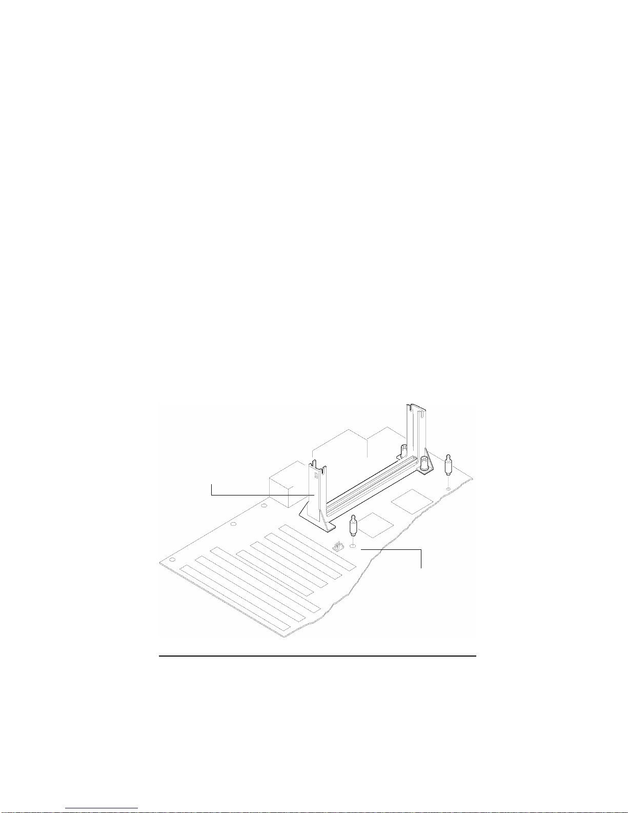
2. Install the retention mechanism attachment mount under the
motherboard. Do this before mounting the motherboard in the
chassis. Do not screw it too tight. Mount the two black plastic pegs
on the motherboard (Figure 2.1). These pegs will be used to attach
the fan/heat sink supports. Notice that one hole and the base of
one peg are larger than the other hole and peg base. Push each
peg into its hole firmly until you hear it "click" into place.
Figure 2-1. Mounting the Pegs
Retention
Mechanism
Large peg and hole
2-1
SUPER P6DGH User’s Manual
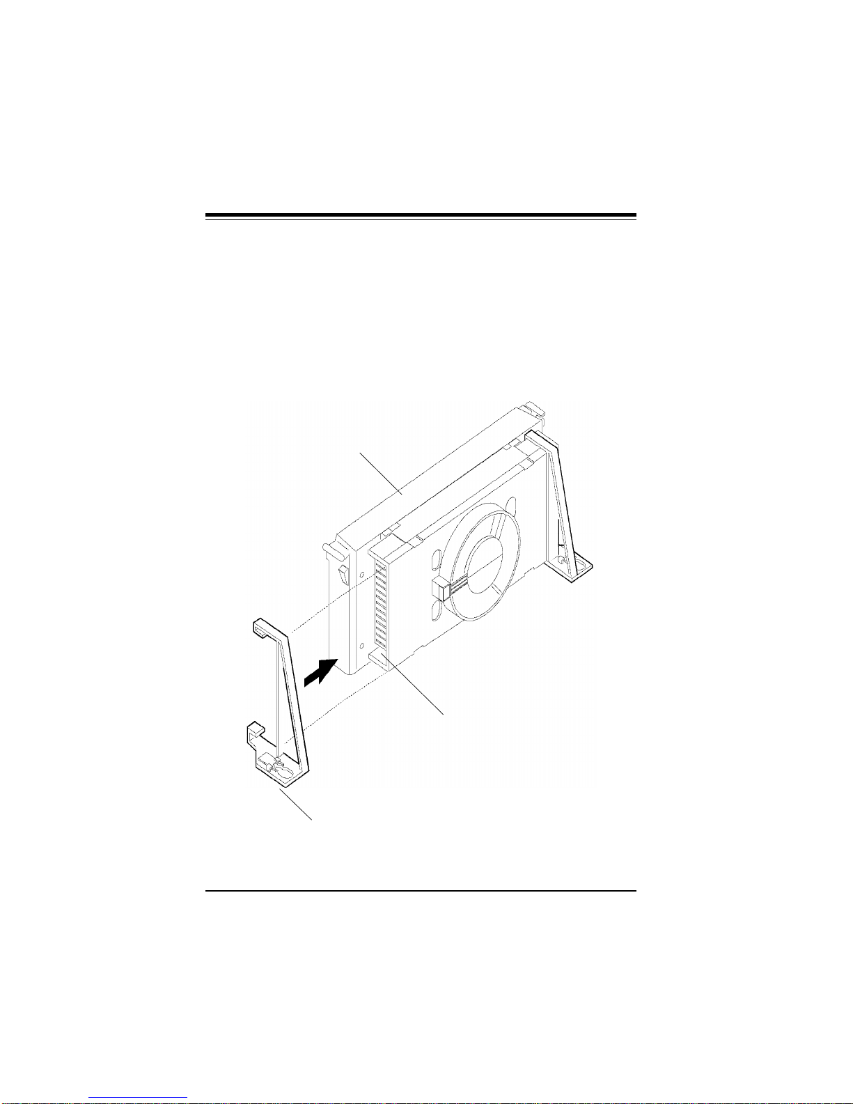
3. Slide a black plastic support onto each end of the fan/heat sink
making sure that the hole and clip are on the outside edge of the
support. If the supports are reversed, the holes will not line up with
the pegs on the motherboard. Slide each support toward the center
of the processor until the support is seated in the outside groove in
the fan housing.
Figure 2-2. Support for Fan/Heat Sink
Top of processor
Groove in fan housing
Hole and clip on outside edge
2-2

Chapter 2: Installation
4. Slid the clip (A) onto each support toward the processor, expos-
ing the hole that will fit over the peg on the motherboard. Push the
latches (B) on the processor toward the center of the processor
until they click into place.
5. Hold the processor so that the fan shroud is facing toward the
pegs on the motherboard. Slide the processor (C) into the retention mechanism and slide the supports onto the pegs. Ensure that
the pegs on the motherboard slide into the holes in the heat sink
support and that the alignment notch in the SEC cartridge fits over
the plug in Slot 1. Push the processor down firmly, with even pressure on both sides of the top, until it is seated.
Figure 2-3. Retention Mechanism
B
C
A
Do not screw in too tight!
2-3
 Loading...