


®
SUPER
®
Pentium System
P5MMA98/P5MMS98
P5MMA2/P5MMS2
USER’S MANUAL
Revision 1.3

The information in this User’s Manual has been carefully reviewed and is believed to be
accurate. The vendor assumes no responsibility for any inaccuracies that may be
contained in this document, makes no commitment to update or to keep current the
information in this manual, or to notify any person or organization of the updates.
SUPERMICRO COMPUTER reserves the right to make changes to the product described in
this manual at any time and without notice. This product, including software, if any, and
documentation may not, in whole or in part, be copied, photocopied, reproduced, translated
or reduced to any medium or machine without prior written consent.
IN NO EVENT WILL SUPERMICRO COMPUTER BE LIABLE FOR DIRECT, INDIRECT,
SPECIAL, INCIDENTAL, OR CONSEQUENTIAL DAMAGES ARISING FROM THE USE OR
INABILITY TO USE THIS PRODUCT OR DOCUMENTATION, EVEN IF ADVISED OF THE
POSSIBILITY OF SUCH DAMAGES. IN PARTICULAR, THE VENDOR SHALL NOT HAVE
LIABILITY FOR ANY HARDWARE, SOFTWARE, OR DATA STORED OR USED WITH THE
PRODUCT, INCLUDING THE COSTS OF THE REPAIRING, REPLACING, OR
RECOVERING SUCH HARDWARE, SOFTWARE, OR DATA.
Unless you request and receive written permission from SUPERMICRO COMPUTER, you
may not copy any part of this document.
Information in this document is subject to change without notice. Other products and
companies referred to herein are trademarks or registered trademarks of their respective
companies or mark holders.
Copyright © 1997 by SUPERMICRO COMPUTER INC.
All rights reserved.
Printed in the United States of America.

Preface
About This Manual
This manual is written for system houses, PC technicians and
knowledgeable PC end users. It provides information for the installation and use of the SUPER P5MMA98/P5MMS98/P5MMA2/P5MMS2
motherboard, which supports the 75/90/100/120/133/150/166/180/
200/233 MHz Intel® Pentium® processor, Cyrix/IBM 5x86, 6x86,
AMD-K5, AMD-K6, MMX
The Intel Pentium processor will take personal computer systems
to a new level of performance. The emergence of the PCI local bus
will also have a significant impact on PCs. Memory and I/O components have also made significant strides in both performance and
integration, enhancing the CPU’s ability to move data quickly. Putting these all together creates the next generation of PC systems.
Manual Organization
Chapter 1, Introduction, describes the features, specifications and
performance of the SUPER P5MMA98/P5MMS98/P5MMA2/P5MMS2
system board, provides detailed information about the chipset,
cache memory, main memory system, PC health monitoring, ACPI,
PC 98 and offers warranty information.
TM
and future Pentium processors.
Refer to Chapter 2, Installation, for instructions on handling staticsensitive devices, checking and/or configuring the jumpers for
manufacturing. Read this chapter when you want to configure CPU
and voltage settings, install or remove SIMM/DIMM memory modules, and to mount the system board in the chassis. Also refer to
this chapter to connect the floppy and hard disk drives, enhanced
IDE configurations, Infrared, USB, parallel port, serial ports, as well
as the cables for the power supply, reset cable, Keylock/Power LED,
speaker, overheat fan and keyboard.
iii

P5MMA98/P5MMA2/P5MMS98/P5MMS2 User's Manual
If you encounter any problem, please see Chapter 3, Troubleshooting, which describes troubleshooting procedures for video, memory, and the setup configuration stored in memory. Instructions are
also included on contacting a technical assistance support representative and returning merchandise for service and the BBS# for
BIOS upgrading.
iv

Preface
Table of Contents
Preface.......................................................................... iii
About This Manual ......................................................................................... iii
Manual Organization...................................................................................... iii
Quick Reference ........................................................................................... viii
Chapter 1: Introduction ............................................. 1-1
1-1 Overview............................................................................................... 1-1
SUPER P5MMA98 Motherboard Layout ................................... 1-4
SUPER P5MMA2 Motherboard Layout ..................................... 1-5
SUPER P5MMS98 Motherboard Layout ................................... 1-6
SUPER P5MMS2 Motherboard Layout ..................................... 1-7
SUPER P5MMA98 Features ....................................................... 1-8
SUPER P5MMA2 Features ....................................................... 1-10
SUPER P5MMS98 Features..................................................... 1-12
SUPER P5MMS2 Features ....................................................... 1-14
1-2 PC Health Monitoring ....................................................................... 1-16
1-3 ACPI/PC 98 Features ....................................................................... 1-19
1-4 Power Supply .................................................................................... 1-21
1-5 Chipset Overview.............................................................................. 1-21
1-6 Super I/O Controller.......................................................................... 1-22
1-7 Warranty, Technical Support, and Service .................................. 1-23
Parts.............................................................................................. 1-23
BIOS .............................................................................................. 1-23
Labor............................................................................................. 1-23
Returns......................................................................................... 1-23
v

Chapter 2: Installation............................................... 2-1
2-1 Static-Sensitive Devices ................................................................... 2-1
Precautions ................................................................................... 2-1
Unpacking...................................................................................... 2-1
2-2 Configuring System Board Jumpers.............................................. 2-2
Manufacturing Settings ............................................................... 2-2
Changing the CPU Speed ......................................................... 2-3
CPU Voltage Settings ................................................................. 2-5
On-Board Memory ........................................................................ 2-6
Cache Size Selection .................................................................. 2-6
Green PC Function ...................................................................... 2-6
2-3 Mounting the Motherboard in the Chassis ................................... 2-6
2-4 Connecting Cables ............................................................................ 2-7
Power Supply Connectors.......................................................... 2-7
PS/2 Keyboard and Mouse Ports ............................................. 2-8
AT Keyboard Connector ............................................................... 2-9
Reset Cable Connector ............................................................ 2-10
Keylock/Power LED Cable Connector ................................... 2-10
Hard Drive LED .......................................................................... 2-11
Speaker Cable Connector........................................................ 2-11
PW_ON Connector ..................................................................... 2-12
Infrared Connector ..................................................................... 2-12
FIR and CIR Connector ............................................................ 2-13
CMOS Clear................................................................................. 2-14
BIOS Flash Protection ............................................................... 2-14
PC Health Monitor IRQ .............................................................. 2-14
Overheat LED .............................................................................. 2-15
External Battery ........................................................................... 2-15
Overheat Fan (2-pin) ................................................................. 2-16
Overheat Fan (3-pin) ................................................................. 2-16
CPU Fan....................................................................................... 2-17
vi

Table of Contents
Chassis Fan ............................................................................... 2-17
Chassis Intrusion Connector .................................................. 2-18
Serial Ports.................................................................................. 2-18
USB Connectors......................................................................... 2-19
Power On/Off State .................................................................... 2-19
2-5 Installing/Removing the SIMM/DIMM Modules ........................... 2-20
SIMM/DIMM Module Installation ............................................... 2-21
Removing SIMM/DIMM Modules .............................................. 2-21
2-6 Connecting Floppy and Hard Disk Drives .................................. 2-22
Parallel Port Connector ............................................................ 2-23
Floppy Connector ....................................................................... 2-24
Enhanced IDE Configurations ................................................ 2-25
Chapter 3: Troubleshooting...................................... 3-1
3-1 Troubleshooting Procedures ........................................................... 3-1
No Video ........................................................................................ 3-1
Troubleshooting Flowchart ........................................................ 3-2
Memory Error ................................................................................. 3-3
Losing the System’s Setup Configuration.............................. 3-3
3-2 Technical Support Procedures........................................................ 3-4
3-3 Returning Merchandise for Service................................................ 3-4
vii

P5MMA98/P5MMA2/P5MMS98/P5MMS2 User's Manual
Quick Reference
Jumpers Function Page
JP2 CMOS Clear 2-14
JP3 External Battery 2-15
JP5, JP6, JP7 Bus Speed 2-3
JP9 (MMA98) Overheat Fan (2 pins) 2-16
JP15 (MMS98) Overheat Fan (2 pins) 2-16
JP24 (MMA98) Power On/Off State 2-19
JP27 (MMS98) Power On/Off State 2-19
J7 Boot Block Protection 2-14
J35, J36 Clock Multiplier 2-3
J45 (MMS98) Overheat LED 2-15
J46, J47, J48, J49 (MMA98) CPU Voltage 2-5
J55 (MMS98) IRQ for PC Health 2-14
J43 (MMA98) IRQ for PC Health 2-14
J42 (MMA98) Overheat LED 2-15
J51, J44 (MMA98) CPU Fan 2-16
J54 (MMS98) CPU Fan 2-16
J41 (MMA98) Overheat Fan (3 pins) 2-16
J53 (MMS98) Overheat Fan (3 pins) 2-16
J58 (MMS98) Chassis Fan 2-17
J59 (MMS98) Chassis Intrusion 2-18
J50 (MMA98) Chassis Intrusion 2-18
J37 (MMS98) USB 2-19
J38 (MMA98) USB 2-19
viii

Chapter 1: Introduction
Chapter 1
Introduction
1-1 Overview
SUPER P5MMA98, P5MMS98, P5MMA2, P5MMS2 are PC 98-ready
motherboards designed to maximize user satisfaction and simplicity in managing the personal computer. The four motherboards
support Intel® Pentium® 233/200/180/166/150/133/120/100/90/75
MHz, Cyrix/IBM 5x86, 6x86, AMD-K5, AMD-K6 and MMXTM processors.
They are based on Intel's advanced 430TX chipset to provide the
best possible platform for multimedia applications. They support
Synchronous DRAM (SDRAM), Concurrent PCI, and 33 MB/s Ultra
DMA for fast disk reads and writes.
All motheboards support PC Health Monitoring features including
CPU fan auto-off in sleep mode, CPU overheat alarm and LED,
hardware BIOS virus protection, and a switching voltage regulator
for the CPU core. SUPER P5MMA98 and P5MMS98 have an LM78
chip on-board which support additional PC Health Monitoring features, including seven voltage monitors, fan status monitors with
firmware/software control on/off, CPU/chassis temperature monitors, Intel LANDesk® Client Manager support, and system resource
alert. A chassis intrusion detection prevents system tampering.
ACPI/PC 98 features include Microsoft® OnNow power management, with a slow blinking LED to indicate the system is in the
sleep state, BIOS support for the USB (Universal Serial Bus) keyboard, and real time clock wake-up alarm. The motherboards provide a main switch override mechanism, and external modem ringon if the system is in a SoftOff state.
SUPER P5MMA98 and P5MMA2 are ATX size (12" x 8.3"). SUPER
P5MMS98 and P5MMS2 are baby AT size (11" x 8.3"). All support up
to 256 MB of FPM, EDO, or SDRAM, with 512 KB pipelined burst
SRAM or L2 cache, using two 168-pin unbuffered 3.3 V DIMM sock-
1-1

SUPER P5MMA98/P5MMS98/P5MMA2/P5MMS2 User’s Manual
ets and four 72-pin 5 V SIMM sockets. They include four PCI and
four ISA slots with two EIDE, one floppy, ECP/EPP parallel port, PS/
2 mouse and keyboard connectors, two 16550-based serial ports,
two USBs, and a fast IR port. SUPER P5MMS98 and P5MMS2 support 2 Mb/s back-up tapes.
Figure 1-1. SUPER P5MMA98 Motherboard Picture
1-2

Chapter 1: Introduction
Figure 1-2. SUPER P5MMS98 Motherboard Picture
For maximum flexibility, all four motherboards support AT or ATXtype power supply. The AMI WinBIOS has a 1 Mb flash memory for
convenient BIOS upgrade. The BIOS supports Advanced Power
Management (APM), Plug and Play, and PC health management.
1-3
SUPER P5MMA98/P5MMS98/P5MMA2/P5MMS2 User’s Manual
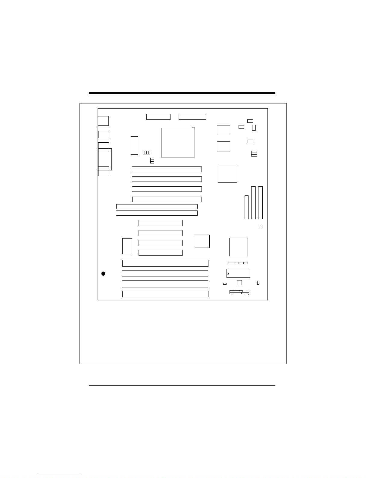
J46
J47
J48
1
J49
PW1
AT POWER
J35
J3611
J40
Bank1
Bank1
Bank2
Bank2
Bank1
Bank0
J4
PS/2 KB
PS/2
MOUSE
J37
USB
J38
J5
COM2
J3
PRINTER
JJ5
COM1
NOTE: DO NOT
POPULATE U6, J33,
AND J34 AT THE
SAME TIME!
®
BATTERY
+
BT2
-
S UPER P5MMA98
——–——— Manufacturer Settings ————
JP2: 1-2 J40: OFF
JP24: 2-3 J43: OPEN
J7: 1-2
——–———————–————––——–—–—
——–—————————–————————
Cyrix/IBM Jumper Settings: p. 2-4
AMD Jumper Settings: p. 2-4
Future CPU Settings: p. 2-5
CPU Voltage Settings: p. 2-5
CMOS Clear: p. 2-14
——–———————–————––——–—–—
J16
ATX POWER
J10
U17
U16
U13
JP3
1 111
U1
J9
J50
LM78
J8
HDD LED/KB LOCK/SPEAKER
1
1 JP23
U14
1
CPU
J34
J33
J32
J31
U6
U5
J14
J13
J12
J11
————–———–—Intel CPU Speed————––—–————
233 OFF OFF 1-2 2-3 2-3 (MMX)
200 OFF ON 1-2 2-3 2-3
180 OFF ON 2-3 2-3 1-2
166 ON ON 1-2 2-3 2-3
150 ON ON 2-3 2-3 1-2 (60 MHz Bus)
150 ON OFF 2-3 1-2 1-2 (75 MHz Bus)
133 ON OFF 1-2 2-3 2-3
120 ON OFF 2-3 2-3 1-2
100 OFF OFF 1-2 2-3 2-3
90 OFF OFF 2-3 2-3 1-2
75 OFF OFF 2-3 2-3 2-3
——–—–——————————–—————————————
U15
JJ10
J36 J35 JP5 JP6 JP7
J41
J44
PMC FAN
J41, JP9: THERMAL FAN
J51
J19
1
FLOPPY
1
U29
JP2
J43
J7
BIOS
U39
IR
PWR SW RESET
1
1
J20 J21
1
IDE 2
JJP23
JP9
JP5
1
JP24
1
J42
JP7
JP6
IDE 1
Figure 1-3. SUPER P5MMA98 Motherboard Layout
1-4
Chapter 1: Introduction
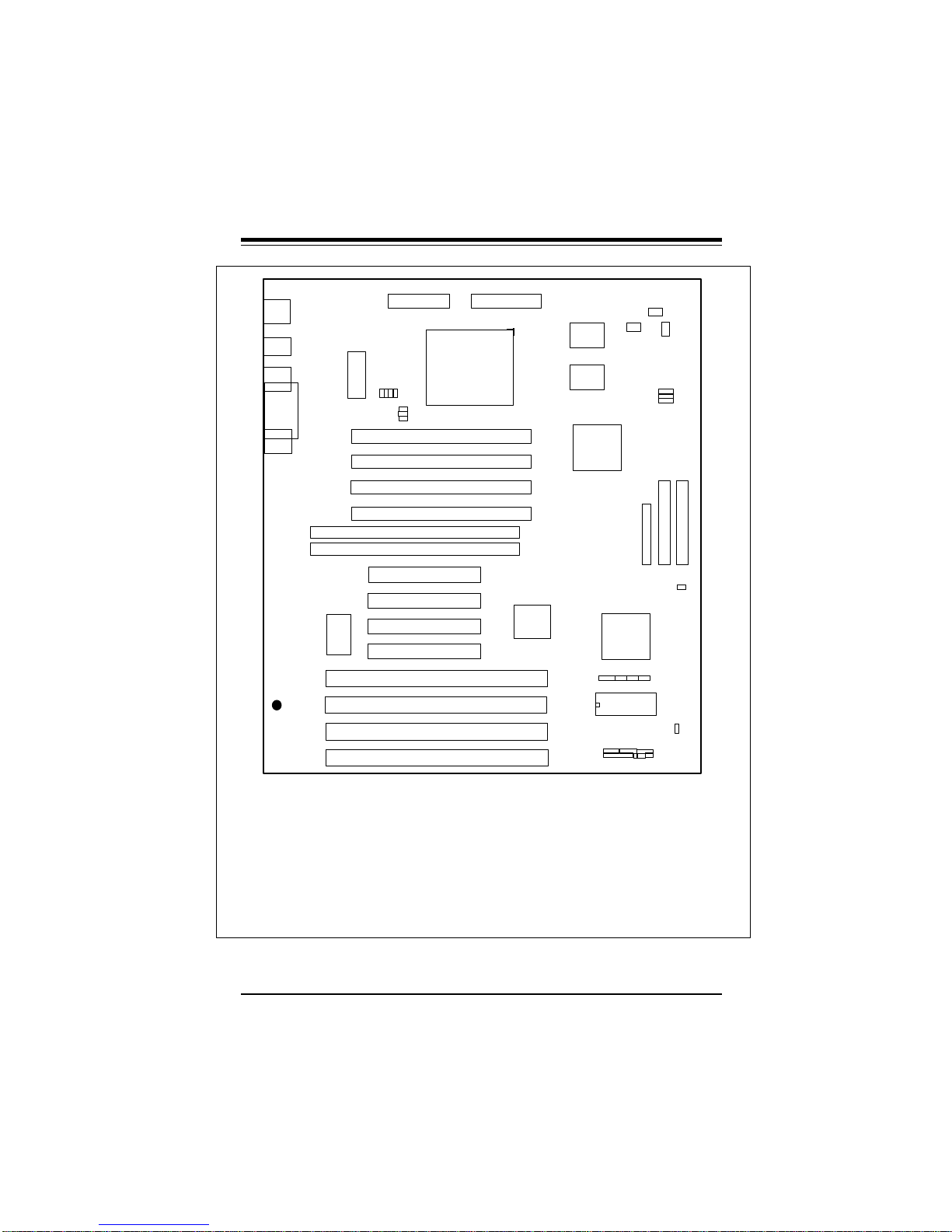
J46
J47
J48
1
PW1
AT POWER
J49
J35
J3611
J40
Bank1
Bank1
Bank2
Bank2
Bank1
Bank0
J4
PS/2 KB
PS/2
MOUSE
J37
USB
J38
J5
COM2
J3
PRINTER
JJ5
COM1
NOTE: DO NOT
POPULATE U6, J33,
AND J34 AT THE
SAME TIME!
®
BATTERY
+
BT2
-
S UPER P5MMA2
——–——— Manufacturer Settings ————
JP2: 1-2 J40: OFF
JP24: 2-3 J43: OPEN
J7: 1-2
——–———————–————––——–—–—
——–—————————–————————
Cyrix/IBM Jumper Settings: p. 2-4
AMD Jumper Settings: p. 2-4
Future CPU Settings: p. 2-5
CPU Voltage Settings: p. 2-5
CMOS Clear: p. 2-14
——–———————–————––——–—–—
J16
ATX POWER
J10
U17
U16
U13
JP3
1 111
U1
J9
J8
HDD LED/KB LOCK/SPEAKER
1
1 JP23
U14
1
CPU
J34
J33
J32
J31
U6
U5
J14
J13
J12
J11
————–———–—Intel CPU Speed————––—–————
233 OFF OFF 1-2 2-3 2-3 (MMX)
200 OFF ON 1-2 2-3 2-3
180 OFF ON 2-3 2-3 1-2
166 ON ON 1-2 2-3 2-3
150 ON ON 2-3 2-3 1-2 (60 MHz Bus)
150 ON OFF 2-3 1-2 1-2 (75 MHz Bus)
133 ON OFF 1-2 2-3 2-3
120 ON OFF 2-3 2-3 1-2
100 OFF OFF 1-2 2-3 2-3
90 OFF OFF 2-3 2-3 1-2
75 OFF OFF 2-3 2-3 2-3
——–—–——————————–—————————————
U15
JJ10
J36 J35 JP5 JP6 JP7
J41
J44
PMC FAN
J41, JP9: THERMAL FAN
1
1
J20 J21
1
J19
1
FLOPPY
U29
JP2
J43
J7
BIOS
JJP23
PWR SWIR
RESET
JP9
JP5
1
IDE 2
JP24
1
J42
JP7
JP6
IDE 1
Figure 1-4. SUPER P5MMA2 Motherboard Layout
1-5
SUPER P5MMA98/P5MMS98/P5MMA2/P5MMS2 User’s Manual
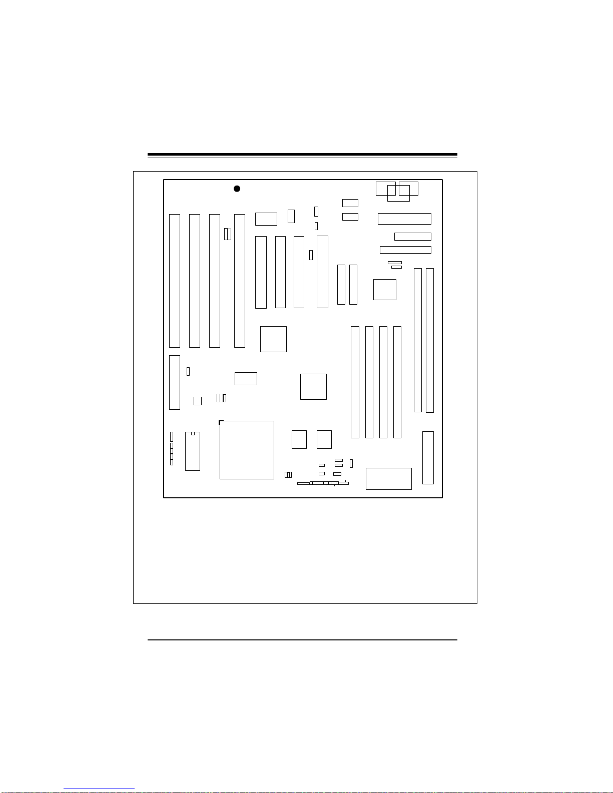
SUPER P5MMS98
J8 J9 J10 J42
J37
J38
USB
J56
J58
U37
SMM SLOT
J551
J51
J50
J49
J48
LM78
U1
BIOS
JP7
JP5
JP6
1
1
®
-
BATTERY
J11 J12
U18
U14
CPU
296-pin ZIF
BT2
U15
JP14
1
+
J47
1
J23
J13
U17 U16
J35
J36
JP2
1
PS/2
JP27
MOUSE
1
J14
JP3
1
EXT
BATTERY
NOTE: DO NOT
POPULATE U6, J33,
AND J34 AT THE
SAME TIME!
U13
JP15
J54
J45
J7
J57
1
HD LED
KEYLOCK PS ON RESET
J53
IDE
# 1
JP10
COM2
JP9
COM1
J20 J21
IDE
# 2
Bank
J59
1
SPEAKER
1
1
1
JP12
PS/2
MOUSE
FIR CON
CONSUMER
IR
Bank1Bank
JP11 AT KB
PW1
JP17
1
1 JP18
U29
J32 J33 J34 J31
Bank
2
PARALLEL
J19
FLOPPY
2
J3
U5
Bank0Bank
JP13
PS/2
KB
J16
U6
1
1
1
ATX POWER
——–——— Manufacturer Settings ————
JP2: 1-2 J47: OFF
JP27: 2-3 J55: OPEN
J7: 1-2
——–———————–————––——–—–—
——–—————————–————————
Cyrix/IBM Jumper Settings: p. 2-4
AMD Jumper Settings: p. 2-4
Future CPU Settings: p. 2-5
CPU Voltage Settings: p. 2-5
CMOS Clear: p. 2-14
——–———————–————––——–—–—
Figure 1-5. SUPER P5MMS98 Motherboard Layout
————–———–—Intel CPU Speed————––—–————
J36 J35 JP5 JP6 JP7
233 OFF OFF 1-2 2-3 2-3 (MMX)
200 OFF ON 1-2 2-3 2-3
180 OFF ON 2-3 2-3 1-2
166 ON ON 1-2 2-3 2-3
150 ON ON 2-3 2-3 1-2 (60 MHz Bus)
150 ON OFF 2-3 1-2 1-2 (75 MHz Bus)
133 ON OFF 1-2 2-3 2-3
120 ON OFF 2-3 2-3 1-2
100 OFF OFF 1-2 2-3 2-3
90 OFF OFF 2-3 2-3 1-2
75 OFF OFF 2-3 2-3 2-3
——–—–——————————–—————————————
1-6
Chapter 1: Introduction
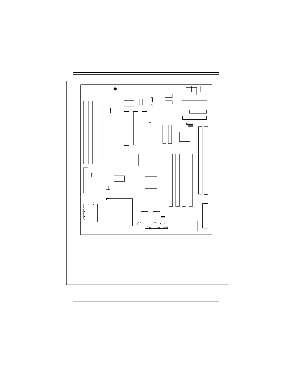
SUPER P5MMS2
J8 J9 J10 J42
J37
J38
USB
J56
J58
SMM SLOT
J551
J51
J50
J49
J48
U1
BIOS
JP7
JP5
JP6
1
1
®
-
BATTERY
J11 J12
U18
U14
CPU
296-pin ZIF
BT2
U15
JP14
1
+
J47
1
J23
PS/2
MOUSE
J13
U17 U16
J35
J36
HD LED
JP2
1
JP27
1
J14
JP3
1
EXT
BATTERY
IDE
# 1
NOTE: DO NOT
POPULATE U6, J33,
AND J34 AT THE
SAME TIME!
U13
J53
JP15
J54
J45
J7
1
J57
KEYLOCK PS ON RESET
JP10
COM2
JP9
COM1
J20 J21
IDE
# 2
Bank
SPEAKER
JP12
PS/2
MOUSE
1
1
1
PW1
FIR CON
CONSUMER
IR
U29
J32 J33 J34 J31
Bank1Bank
JP11 AT KB
JP17
1
1 JP18
Bank
2
PARALLEL
J19
FLOPPY
2
J3
U5
Bank0Bank
JP13
PS/2
KB
U6
J16
1
1
1
ATX POWER
——–——— Manufacturer Settings ————
JP2: 1-2 J47: OFF
JP27: 2-3 J55: OPEN
J7: 1-2
——–———————–————––——–—–—
——–—————————–————————
Cyrix/IBM Jumper Settings: p. 2-4
AMD Jumper Settings: p. 2-4
Future CPU Settings: p. 2-5
CPU Voltage Settings: p. 2-5
CMOS Clear: p. 2-14
——–———————–————––——–—–—
Figure 1-6. SUPER P5MMS2 Motherboard Layout
————–———–—Intel CPU Speed————––—–————
J36 J35 JP5 JP6 JP7
233 OFF OFF 1-2 2-3 2-3 (MMX)
200 OFF ON 1-2 2-3 2-3
180 OFF ON 2-3 2-3 1-2
166 ON ON 1-2 2-3 2-3
150 ON ON 2-3 2-3 1-2 (60 MHz Bus)
150 ON OFF 2-3 1-2 1-2 (75 MHz Bus)
133 ON OFF 1-2 2-3 2-3
120 ON OFF 2-3 2-3 1-2
100 OFF OFF 1-2 2-3 2-3
90 OFF OFF 2-3 2-3 1-2
75 OFF OFF 2-3 2-3 2-3
——–—–——————————–—————————————
1-7

SUPER P5MMA98/P5MMS98/P5MMA2/P5MMS2 User’s Manual
SUPER P5MMA98 Features
The following list covers the general features of SUPER P5MMA98.
CPU
• Pentium 233, 200, 180, 166, 150, 133, 120, 100, 90, 75 MHz,
MMXTM, Cyrix/IBM 5x86, 6x86, AMD-K5, K6, and future processors
Cache
• 512 KB pipelined burst synchronous secondary cache
Memory
• 256 MB of SDRAM, EDO or Fast Page DRAM memory
• 4 72-pin 5V SIMM sockets and 2 168-pin unbuffered 3.3V DIMM
sockets
Chipset
• Intel 430TX
Expansion Slots
• 4 PCI slots and 4 ISA slots
PC Health Monitoring (LM78)
• Seven on-board voltage monitors
• Three-fan status monitors with firmware/software control on/off
• CPU/chassis temperature control
• CPU fan auto-off in sleep mode
• CPU overheat control, alarm, and LED
• Chassis intrusion detection
• System resource alert
• Hardware BIOS virus protection
• Switching voltage regulator for the CPU core
• Intel LANDesk® Client Manager (LDCM) support
ACPI/PC 98 Features
• Microsoft OnNow (ATX power only)
• Slow blinking LED for sleep-state indicator
• BIOS support for USB keyboard
• Real time clock wake-up alarm
• Main switch override mechanism
• External modem ring-on if system is in SoftOff state
1-8

Chapter 1: Introduction
BIOS
• AMI® Flash BIOS with 1 Mb flash memory
• Advanced Power Management (APM) Green PC Function
• Plug and Play (PnP) and boot block support
• Desktop Management Interface 2.0 (DMI)
On-Board I/O
• 2 EIDE interfaces support Mode 4, Ultra DMA Modes 0, 1, 2 with
transfer rates up to 33 MB/s
• 1 floppy interface
• 2 Fast UART 16550 serial ports
• EPP (Enhanced Parallel Port) and ECP (Extended Capabilities
Port) parallel port
• PS/2 mouse and PS/2 keyboard, 2 USB ports, Infra-red port
Power Supply
• ATX power supply (AT optional)
Board Type
• ATX size (12" x 8.3")
1-9

SUPER P5MMA98/P5MMS98/P5MMA2/P5MMS2 User’s Manual
SUPER P5MMA2 Features
The following list covers the general features of SUPER P5MMA2.
CPU
• Pentium 233, 200, 180, 166, 150, 133, 120, 100, 90, 75 MHz,
MMXTM, Cyrix/IBM 5x86, 6x86, AMD-K5, K6, and future processors
Cache
• 512 KB pipelined burst synchronous secondary cache
Memory
• 256 MB of SDRAM, EDO or Fast Page DRAM memory
• 4 72-pin 5V SIMM sockets and 2 168-pin unbuffered 3.3V DIMM
sockets
Chipset
• Intel 430TX
Expansion Slots
• 4 PCI slots and 4 ISA slots
PC Health Monitoring
• CPU fan auto-off in sleep mode
• CPU overheat control, alarm, and LED
• Hardware BIOS virus protection
• Switching voltage regulator for the CPU core
ACPI/PC 98 Features
• Microsoft OnNow (ATX power only)
• Slow blinking LED for sleep-state indicator
• BIOS support for USB keyboard
• Real time clock wake-up alarm
• Main switch override mechanism
• External modem ring-on if system is in SoftOff state
BIOS
• AMI® Flash BIOS with 1 Mb flash memory
• Advanced Power Management (APM) Green PC Function
• Plug and Play (PnP) and boot block support
• Desktop Management Interface 2.0 (DMI)
1-10

Chapter 1: Introduction
On-Board I/O
• 2 EIDE interfaces support Mode 4, Ultra DMA Modes 0, 1, 2 with
transfer rates up to 33 MB/s
• 1 floppy interface
• 2 Fast UART 16550 serial ports
• EPP (Enhanced Parallel Port) and ECP (Extended Capabilities
Port) parallel port
• PS/2 mouse and PS/2 keyboard
• 2 USB ports, Infra-red port
Power Supply
• ATX power supply (AT optional)
Board Type
• ATX size (12" x 8.3")
1-11

SUPER P5MMA98/P5MMS98/P5MMA2/P5MMS2 User’s Manual
SUPER P5MMS98 Features
The following list covers the general features of SUPER P5MMS98.
CPU
• Pentium 233, 200, 180, 166, 150, 133, 120, 100, 90, 75 MHz,
MMXTM, Cyrix/IBM 5x86, 6x86, AMD-K5, K6, and future processors
Cache
• 512 KB pipelined burst synchronous secondary cache
Memory
• 256 MB of SDRAM, EDO or Fast Page DRAM memory
• 4 72-pin 5V SIMM sockets and 2 168-pin unbuffered 3.3V DIMM
sockets
Chipset
• Intel 430TX
Expansion Slots
• 4 PCI slots and 4 ISA slots
PC Health Monitoring (LM78)
• Seven on-board voltage monitors
• Three-fan status monitors with firmware/software control on/off
• CPU/chassis temperature control
• CPU fan auto-off in sleep mode
• CPU overheat control, alarm, and LED
• Chassis intrusion detection
• System resource alert
• Hardware BIOS virus protection
• Switching voltage regulator for the CPU core
• Intel LANDesk® Client Manager (LDCM) support
ACPI/PC 98 Features
• Microsoft OnNow (ATX power only)
• Slow blinking LED for sleep-state indicator
• BIOS support for USB keyboard
• Real time clock wake-up alarm
• Main switch override mechanism
• External modem ring-on if system is in SoftOff state
1-12
 Loading...