

Supero X8DTL-3, Supero X8DTL-i, Supero X8DTL-3F, Supero X8DTL-iF, X8DTL-i User Manual
...
X8DTL-3
X8DTL-i
X8DTL-3F
X8DTL-iF
USER’S MANUAL
Revision 1.2a

The information in this User’s Manual has been carefully reviewed and is believed to be accurate.
The vendor assumes no responsibility for any inaccuracies that may be contained in this document,
makes no commitment to update or to keep current the information in this manual, or to notify any
person or organization of the updates. Please Note: For the most up-to-date version of this
manual, please see our web site at www.supermicro.com.
Super Micro Computer, Inc. ("Supermicro") reserves the right to make changes to the product
described in this manual at any time and without notice. This product, including software and documentation, is the property of Supermicro and/or its licensors, and is supplied only under a license.
Any use or reproduction of this product is not allowed, except as expressly permitted by the terms
of said license.
IN NO EVENT WILL SUPERMICRO BE LIABLE FOR DIRECT, INDIRECT, SPECIAL, INCIDENTAL,
SPECULATIVE OR CONSEQUENTIAL DAMAGES ARISING FROM THE USE OR INABILITY TO
USE THIS PRODUCT OR DOCUMENTATION, EVEN IF ADVISED OF THE POSSIBILITY OF
SUCH DAMAGES. IN PARTICULAR, SUPERMICRO SHALL NOT HAVE LIABILITY FOR ANY
HARDWARE, SOFTW ARE, OR DA TA STORED OR USED WITH THE PRODUCT, INCLUDING THE
COSTS OF REPAIRING, REPLACING, INTEGRATING, INSTALLING OR RECOVERING SUCH
HARDWARE, SOFTWARE, OR DATA.
Any disputes arising between manufacturer and customer shall be governed by the laws of Santa
Clara County in the State of California, USA. The State of California, County of Santa Clara shall
be the exclusive venue for the resolution of any such disputes. Super Micro's total liability for all
claims will not exceed the price paid for the hardware product.
FCC Statement: This equipment has been tested and found to comply with the limits for a Class
A digital device pursuant to Part 15 of the FCC Rules. These limits are designed to provide
reasonable protection against harmful interference when the equipment is operated in a commercial
environment. This equipment generates, uses, and can radiate radio frequency energy and, if not
installed and used in accordance with the manufacturer’s instruction manual, may cause harmful
interference with radio communications. Operation of this equipment in a residential area is likely
to cause harmful interference, in which case you will be required to correct the interference at your
own expense.
California Best Management Practices Regulations for Perchlorate Materials: This Perchlorate
warning applies only to products containing CR (Manganese Dioxide) Lithium coin cells. “Perchlorate
Material-special handling may apply. See www.dtsc.ca.gov/hazardouswaste/perchlorate”
WARNING: Handling of lead solder materials used in this
product may expose you to lead, a chemical known to
the State of California to cause birth defects and other
reproductive harm.
Manual Revision 1.2a
Release Date: Sept. 23, 2011
Unless you request and receive written permission from Super Micro Computer, Inc., you may not
copy any part of this document.
Information in this document is subject to change without notice. Other products and companies
referred to herein are trademarks or registered trademarks of their respective companies or mark
holders.
Copyright © 2011 by Super Micro Computer, Inc.
All rights reserved.
Printed in the United States of America
Preface
About this Manual
This manual is written for system integrators, PC technicians and knowledgeable PC
users. It provides information for the installation and use of the
X8DTL-i/X8DTL-3F/X8DTL-iF motherboard.
About this Motherboard
The X8DTL-3/X8DTL-i/X8DTL-3F/X8DTL-iF supports the Intel® 5500/5600
Series Processor, the fi rst dual-processing platform that supports the Intel Quick-
Path Interconnect (QPI) Technology, providing the next generation point-to-point
system interface to replace the current Front Side Bus. With the Intel 5500/5600
Series Processor built in, the X8DTL-3/X8DTL-i/X8DTL-3F/X8DTL-iF substantially
enhances system performance with increased bandwidth and unprecedented scalability optimized for high-end HCP/Cluster systems and intensive applications.
Please refer to our web site (http://www.supermicro.com/products/) for updates on
processor and memory support. This product is intended to be installed and serviced
by professional technicians.
X8DTL-3/
Preface
Manual Organization
Chapter 1 describes the features, specifi cations and performance of the mother-
board and provides detailed information about the chipset.
Chapter 2 provides hardware installation instructions. Read this chapter when in-
stalling the processor, memory modules and other hardware components into the
system. If you encounter any problems, see Chapter 3, which describes troubleshooting procedures for video, memory and system setup stored in the CMOS.
Chapter 4 includes an introduction to the BIOS and provides detailed information
on running the CMOS Setup utility.
Appendix A lists BIOS POST Error Codes. Appendix B provides Software Installation Instructions.
Conventions Used in the Manual
Special attention should be given to the following symbols for proper installation and
to prevent damage done to the components or injury to yourself:
iii

X8DTL-3/X8DTL-i/X8DTL-3F/X8DTL-iF User's Manual
Danger/Caution: Instructions to be strictly followed to prevent catastrophic
system failure or to avoid bodily injury.
Warning: Important information given to ensure proper system installation
or to prevent damage to the components.
Note: Additional Information given to differentiate various models or to
ensure correct system setup.
iv

Contacting Supermicro
Contacting Supermicro
Headquarters
Address: Super Micro Computer, Inc.
980 Rock Ave.
San Jose, CA 95131 U.S.A.
Tel: +1 (408) 503-8000
Fax: +1 (408) 503-8008
Email: marketing@supermicro.com (General Information)
support@supermicro.com (Technical Support)
Web Site: www.supermicro.com
Europe
Address: Super Micro Computer B.V.
Het Sterrenbeeld 28, 5215 ML
's-Hertogenbosch, The Netherlands
Tel: +31 (0) 73-6400390
Fax: +31 (0) 73-6416525
Email: sales@supermicro.nl (General Information)
support@supermicro.nl (Technical Support)
rma@supermicro.nl (Customer Support)
Asia-Pacifi c
Address: Super Micro Computer, Inc.
4F, No. 232-1, Liancheng Rd.
Chung-Ho 235, Taipei County
Taiwan, R.O.C.
Tel: +886-(2) 8226-3990
Fax: +886-(2) 8226-3991
Web Site: www.supermicro.com.tw
Email: support@supermicro.com.tw (Technical Support)
Tel: +886-(2) 8226-5990 (Technical Support)
v

X8DTL-3/X8DTL-i/X8DTL-3F/X8DTL-iF User's Manual
Table of Contents
Preface
Chapter 1 Introduction
1-1 Overview .........................................................................................................1-1
1-2 Chipset Overview ............................................................................................1-9
1-3 Special Features ...........................................................................................1-10
1-4 PC Health Monitoring .................................................................................... 1-10
1-5 ACPI Features ................................................................................................1-11
1-6 Power Supply ................................................................................................1-12
1-7 Super I/O ....................................................................................................... 1-12
1-8 Overview of the Nuvoton WPCM450R Controller (For X8DTL-3F/X8DTL-iF
Only) ......................................................................................................................1-13
Chapter 2 Installation
2-1 Static-Sensitive Devices ..................................................................................2-1
2-2 Motherboard Installation ..................................................................................2-2
2-3 Processor and Heatsink Installation................................................................2-3
2-4 Installing and Removing the Memory Modules ...............................................2-7
2-5 Control Panel Connectors/IO Ports................................................................2-11
1. Back Panel Connectors/IO Ports ...............................................................2-11
ATX PS/2 Keyboard and PS/2 Mouse Ports ............................................2-12
Universal Serial Bus (USB) ...................................................................... 2-13
Serial Ports ............................................................................................... 2-14
Video Connector .......................................................................................2-14
Ethernet Ports .......................................................................................... 2-15
2. Front Control Panel ...................................................................................2-16
3. Front Control Panel Pin Defi nitions .......................................................... 2-17
NMI Button ............................................................................................... 2-17
Power LED ..............................................................................................2-17
HDD LED .................................................................................................. 2-18
NIC1/NIC2 LED Indicators ....................................................................... 2-18
Overheat (OH)/Fan Fail/PWR Fail/UID LED ............................................ 2-19
Power Fail LED ........................................................................................ 2-19
Reset Button ........................................................................................... 2-20
Power Button ........................................................................................... 2-20
2-6 Connecting Cables ........................................................................................ 2-21
Power Connectors ...................................................................................2-21
Fan Headers ............................................................................................. 2-22
Chassis Intrusion .....................................................................................2-22
vi

Table of Contents
Internal Speaker .......................................................................................2-23
Power LED/Speaker ................................................................................. 2-23
Wake-On-LAN ..........................................................................................2-24
Overheat LED/Fan Fail (JOH1) ................................................................2-24
T-SGPIO 1/2 & 3-SGPIO 1/2 Headers .....................................................2-25
I-Button (For X8DTL-3/3F only)................................................................2-25
Power SMB (I
2
C) Connector .................................................................... 2-26
IPMB .........................................................................................................2-26
Unit Identifi cation Switch/LEDs ................................................................ 2-27
DOM Power Connector ............................................................................ 2-27
Wake-On-Ring ..........................................................................................2-28
2-7 Jumper Settings ............................................................................................2-29
Explanation of Jumpers ................................................................................2-29
GLAN Enable/Disable ..............................................................................2-29
CMOS Clear ............................................................................................. 2-30
Watch Dog Enable/Disable ...................................................................... 2-30
2
I
C Bus to PCI-Exp. Slots ........................................................................2-31
VGA Enable .............................................................................................. 2-31
SAS Enable/Disable (X8DTL-3/X8DTL-3F only) ...................................... 2-32
SAS RAID Mode Select (X8DTL-3/X8DTL-3F only) ................................ 2-32
2-8 Onboard LED Indicators ...............................................................................2-33
GLAN LEDs .............................................................................................. 2-33
IPMI Dedicated LAN LEDs (X8DTL-iF/-3F) ............................................. 2-33
SAS Heartbeat LED (X8DTL-3/-3F) ......................................................... 2-34
BMC Heartbeat LED (X8DTL-iF/3F) ........................................................ 2-34
Onboard Power LED ............................................................................... 2-35
Rear UID LED ......................................................................................... 2-35
2-9 Serial ATA and SAS Connections ................................................................. 2-36
Serial ATA Ports........................................................................................ 2-36
SAS Ports (X8DTL-3/X8DTL-3F only) ...................................................... 2-36
Chapter 3 Troubleshooting
3-1 Troubleshooting Procedures ........................................................................... 3-1
Before Power On ............................................................................................ 3-1
No Power ........................................................................................................ 3-1
No Video ......................................................................................................... 3-1
Losing the System’s Setup Confi guration ....................................................... 3-2
Memory Errors ...............................................................................................3-2
3-2 Technical Support Procedures ........................................................................3-2
3-3 Frequently Asked Questions ...........................................................................3-3
vii

X8DTL-3/X8DTL-i/X8DTL-3F/X8DTL-iF User's Manual
3-4 Returning Merchandise for Service.................................................................3-4
Chapter 4 BIOS
4-1 Introduction ...................................................................................................... 4-1
Starting BIOS Setup Utility ..............................................................................4-1
How To Change the Confi guration Data ......................................................... 4-1
Starting the Setup Utility ................................................................................. 4-2
4-2 Main Setup ......................................................................................................4-2
4-3 Advanced Setup Confi gurations...................................................................... 4-4
Power Confi guration ........................................................................................ 4-5
4-4 Security Settings ........................................................................................... 4-24
4-5 Boot Confi guration ........................................................................................4-25
4-6 Exit Options ................................................................................................... 4-27
Appendix A BIOS Error Beep Codes
Appendix B Software Installation Instructions
B-1 Installing Software Programs .........................................................................B-1
B-2 Confi guring Supero Doctor III .........................................................................B-2
viii

Chapter 1: Introduction
Chapter 1
Introduction
1-1 Overview
Checklist
Congratulations on purchasing your computer motherboard from an acknowledged
leader in the industry. Supermicro boards are designed with the utmost attention
to detail to provide the highest standards in quality and performance. Check that
the following items have all been included with your motherboard. If anything listed
here is damaged or missing, contact your retailer.
The following items are included in the retail box.
One (1) Supermicro Mainboard
•
Eight (8) Serial ATA cables (CBL-0044L) (For X8DTL-3/X8DTL-3F)•
Six (6) Serial ATA cables (CBL-0044L) (For X8DTL-i/X8DTL-iF)•
One (1) I/O backpanel shield (CSE-PT7L) (X8DTL-3/i)•
One (1) I/O backpanel shield (MCP-260-00027-0N) (X8DTL-3F/iF)•
One (1) Supermicro CD containing drivers and utilities•
One (1) User's/BIOS Manual•
1-1
X8DTL-3/X8DTL-i/X8DTL-3F/X8DTL-iF User's Manual
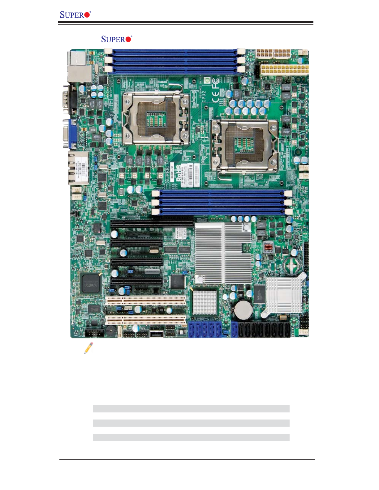
X8DTL-3/X8DTL-i/X8DTL-3F/X8DTL-iF Image
Note: The drawings and pictures shown in this manual were based on the
latest PCB Revision available at the time of publishing of the manual. The
motherboard you’ve received may or may not look exactly the same as
the graphics shown in the manual. Refer to the table below for the differences between the models.
Differences between X8DTL-3/X8DTL-i/X8DTL-3F/ X8DTL-iF
SATA (ICH10R) Yes Yes Yes Yes
SAS (1068E) Yes No Yes No
3-SGPIO 1/2 Yes No Yes No
I-Button Yes No Yes No
IPMI 2.0 w/KVM No No Yes Yes
X8DTL-3 X8DTL-i X8DTL-3F X8DTL-iF
1-2
Chapter 1: Introduction
1
COM1
VGA
USB0/1
FAN6
LE2
W8379
D20
FAN5
UID
5ADG
W8352
BMC CTRL
WPCM450-R
KB/Mouse
LAN1
LAN2
BMC
7HG
COM2
PHY
Chip
IPMI LAN
JPL1
JPL2
LAN
CTRL
LAN
CTRL
Flash ROM
JPG1
JWOR
JWD
Buzzer
SP1
JI2C2
JI2C1
JD1
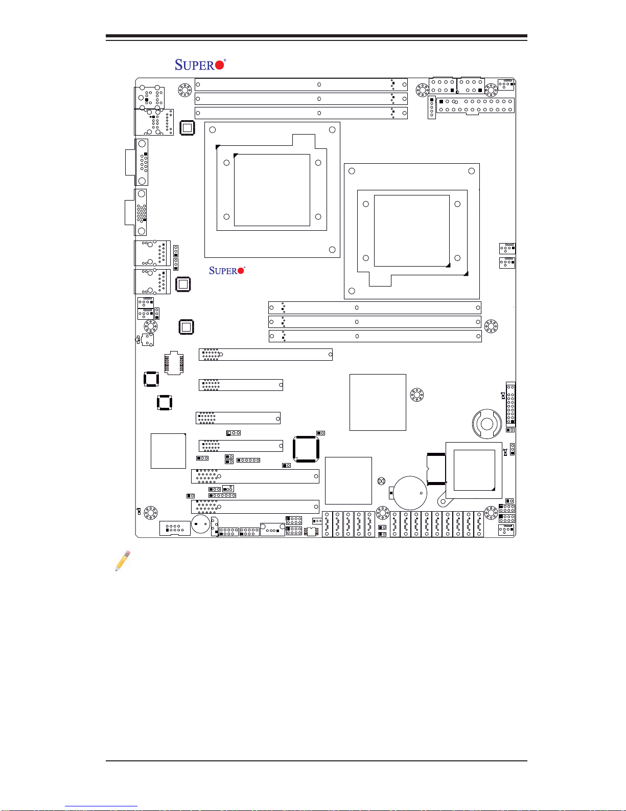
X8DTL-3/X8DTL-i/X8DTL-3F/X8DTL-iF Layout
P1-DIMM3A
SAS0
SAS1
JPI2C
SAS2
JPW3
SAS3
CPU1
X8DTL Series
Slot6 PCI-E 2.0 x8 (in x16 Slot)
Slot5 PCI-E 2.0 x4 (in x8 Slot)
Slot4 PCI-E 2.0 x8
JPB
Slot2 PCI 33MHz
JWOL
Slot1 PCI 33MHz
USB4/5
(in x8 Slot)
J16
USB6
Slot3 PCI-E 1.0 x4
IPMB
USB2/3
T-SGPIO1
P1-DIMM2A
P1-DIMM1A
Rev. 2.01
LC4128ZE-
7TN100C
BIOS
T-SGPIO2
JWF1
CPU2
P2-DIMM1A
P2-DIMM2A
P2-DIMM3A
Intel
5500
(North Bridge)
JP5
Intel
ICH10R
(South Bridge)
I-SATA5
I-SATA4
JBT1
Battery
JBAT1
JPS2
I-SATA2
I-SATA3
I-SATA0
I-SATA1
JP3
LSI SAS1068E
SAS4
JPW2
JPW1
SAS5
SAS6
I-Button
3-SGPIO1
3-SGPIO2
SAS7
FAN1/
CPU1 FAN
FAN2/
CPU2FAN
FAN3
LE1
JF1
JOH1
LES2
JL1
FAN4
1
JPS1
Notes
The DOM Power connector (JWF1) and the Wake-On-Ring header (JWOR), 1.
are supported by the PCB Rev. 2.01 or a newer version board only.
SAS Ports, SAS jumpers, the I-Button, and the LSI 1068E chip are available 2.
on the X8DTL-3/-3F only. For SAS RAID confi guration, refer to the LSI User
Guide posted at our website at http://www.supermicro.com/support/manuals/
IPMI 2.0, the PHY chip, and the Dedicated LAN (w/KVM support) are avail-3.
able on the X8DTL-3F/-iF only. For mo+re information, refer to the IPMI user
guide posted on our website at http://www.supermicro.com/support/manuals/.
1-3
X8DTL-3/X8DTL-i/X8DTL-3F/X8DTL-iF User's Manual
1
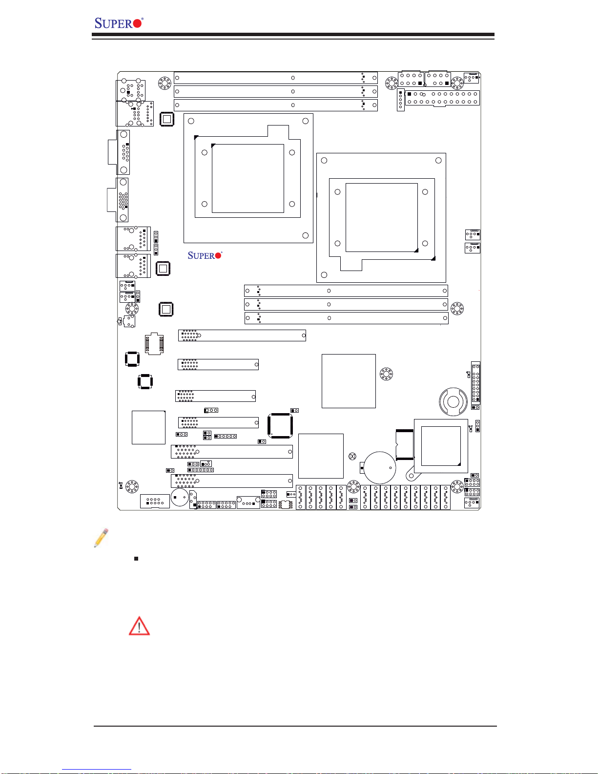
Quick Reference
P1-DIMM3A
CPU1
USB6
T-SGPIO1
P1-DIMM2A
P1-DIMM1A
Rev. 2.01
LC4128ZE-
7TN100C
BIOS
T-SGPIO2
JWF1
CPU2
P2-DIMM1A
P2-DIMM2A
P2-DIMM3A
Intel
5500
(North Bridge)
JP5
Intel
ICH10R
(South Bridge)
I-SATA5
I-SATA4
JBT1
Battery
JBAT1
JPS2
I-SATA2
I-SATA1
I-SATA3
JP3
SAS1
SAS0
I-SATA0
COM1
VGA
USB0/1
FAN6
LE2
W8379
D20
FAN5
UID
5ADG
W8352
BMC CTRL
WPCM450-R
KB/Mouse
LAN1
LAN2
BMC
7HG
COM2
PHY
Chip
IPMI LAN
JPL1
JPL2
LAN
CTRL
LAN
CTRL
Flash ROM
JPG1
JWOR
Buzzer
SP1
JWD
JI2C2
JI2C1
JD1
X8DTL Series
Slot6 PCI-E 2.0 x8 (in x16 Slot)
Slot5 PCI-E 2.0 x4 (in x8 Slot)
Slot4 PCI-E 2.0 x8
JPB
Slot3 PCI-E 1.0 x4
IPMB
USB2/3
(in x8 Slot)
J16
Slot2 PCI 33MHz
JWOL
Slot1 PCI 33MHz
USB4/5
Notes
Jumpers not indicated are for test purposes only. •
JPI2C
SAS2
JPW3
SAS3
LSI SAS1068E
SAS4
JPW2
JPW1
SAS5
SAS6
I-Button
3-SGPIO1
3-SGPIO2
SAS7
FAN1/
CPU1 FAN
FAN2/
CPU2FAN
FAN3
LE1
JF1
JOH1
LES2
JL1
FAN4
1
JPS1
" " indicates the location of Pin 1.•
When LE1 is on, the onboard power connection is on. Make sure to unplug the •
power cables before removing or installing components.
Warning! 1. To prevent damage to the power supply or motherboard,
please use a power supply that contains a 24-pin and two 8-pin power
connectors. Be sure to connect these connectors to the 24-pin (JPW1)
and the two 8-pin (JPW2, JPW3) power connectors on the motherboard.
Failure in doing so will void the manufacturer warranty on your power supply and motherboard. 2. To avoid possible system overheating, be sure to
provide adequate airfl ow to the system.
1-4

Chapter 1: Introduction
X8DTL-3/X8DTL-3F/ X8DTL-i/ X8DTL-iF Quick Reference
Jumper Description Default Setting
JBT1 CMOS Clear Open (Normal)
2
C1/JI2C2 SMB to PCI/PCI-E Slots Open/Open (Disabled)
JI
JPG1 VGA Enabled Pins 1-2 (Enabled)
JPL1/JPL2 LAN1/2 Enable Pins 1-2 (Enabled)
JPS1 SAS Enable Pins 1-2 (Enabled) (X8DTL-3/3F)
JPS2 SAS RAID Select Closed (SR RAID Enabled) (X8DTL-3/3F)
JWD Watch Dog Pins 1-2 (Reset)
Connector Description
COM1/COM2 COM1/COM2 Serial Port/Header
FAN 1-6 System/CPU Fan Headers (Fans 1~2: CPU Fans)
I-Button I-Button for RAID data storage (for X8DTL-3/3F only)
2
IPMB IPMB I
2
C Power Supply SMBbus I2C Header
JPI
C Header (for an IPMI card) (for X8DTL-iF/3F only)
JD1 PWR LED/Speaker Header (Pins 4~7: Speaker)
JF1 Front Panel Connector
JL1 Chassis Intrusion Header
JOH1 Overheat LED Header
JPW1, JPW2/JPW3 24-pin ATX PWR, 8-pin Secondary PWR (*Warning P. 1-4)
JWF1 DOM (Disk-On-Module) Power Connector (Note 1 on P.1-3.)
JWOL Wake-On-LAN Header
JWOR Wake-On-Ring Header (See Note 1 on P. 1-3.)
LAN1/2, Dedicated LAN G-LAN (RJ45) Ports (Dedicated LAN: X8DTL-iF/3F)
I-SATA0 ~ I-SATA5 (Intel South Bridge) SATA Ports
SAS 0~7 SAS Ports 0~7 (for X8DTL-3/-3F only)
SP1 Internal Buzzer
3-SGPIO-1/3-SGPIO-2 Serial General Purpose I/O Headers for SAS (X8DTL-3/3F)
T-SGPIO-1/T-SGPIO-2 Serial General Purpose I/O Headers for SATA
USB 0/1, 2/3, 4/5, 6 Universal Serial Bus (USB) Ports
UID Rear Unit Identify Switch
VGA VGA Con nec tor
LED Description
D20 BMC Heartbeat LED Indicator
LE1 O nboa rd St andby L ED Ind ica tor
LE2 Rear UID LED
LES2 SAS Heartbeat LED
1-5

X8DTL-3/X8DTL-i/X8DTL-3F/X8DTL-iF User's Manual
Motherboard Features
CPU
Two Intel•
ing two full-width Intel QuickPath Interconnect (QPI) @6.4 GT/s with a total of
up to 51.2 GB/s Data Transfer Rate (6.4 GB/s per direction)
®
5500/5600* Series (LGA 1366) processors, each processor support-
(*Note 1 on P. 1-3.)
Memory
Six 240-pin DIMM sockets support up to 96 GB Reg. ECC or 24 GB Unbuffered •
ECC/Non-ECC DDR3 1333 MHz/1066 MHz/ 800 MHz Memory modules (See
Section 2-4 in Chapter 2 for DIMM Slot Population.)
Chipset
Intel 5500 chipset, including: the 5500 (IOH-24D) and the ICH10R (South •
Bridge).
Expansion Slots
One PCI-E 2.0 x8 (in x16) slot (Slot 6)•
One PCI-E 2.0 x8 slot (Slot 4)•
One PCI-E 2.0 x4 (in x8) slot (Slot 5)•
One PCI-E 1.0 x4 (in x8) (Slot 3)•
Two 32-bit PCI 33 slot (Slot 1 and Slot 2)•
BIOS
32 Mb AMI SPI Flash ROM•
PCI 2.2, ACPI 1.0/2.0/3.0, Plug and Play (PnP), DMI 2.3, USB Keyboard sup-•
port, and SMBIOS 2.3
PC Health Monitoring
Onboard voltage monitors for CPU1 Vcore, CPU2 Vcore, CPU2 DIMM, CPU1 •
DIMM, 5V, 5VSB, 12V, -12V, 3.3Vcc, 3.3VSB, VBAT and Vtt.
Fan status monitor with fi rmware control and CPU fan auto- of f in sl eep mod e
•
Platfo rm Environme nt Control In terfac e (PECI) ready and The rmal Moni tor 2 •
(TM2) support
CPU/chas sis tempe rature m onitor s and CPU sl ow- down on ove rheat
•
Pulse Wi dth Mo dulati on (PW M) Fan Contr ol •
CPU ther mal tr ip supp or t for pro ces sor pr otecti on, power L ED•
Power-up mod e cont rol for r ecover y fr om AC power l oss•
Auto- switc hing vol tage r egulato r for CPU c ore s•
System over heat /Fan Fail LED I ndic ator and c ontr ol•
Chassis i ntrus ion detec tion•
System re sourc e aler t vi a Super o Doc tor III•
1-6

Chapter 1: Introduction
ACPI Features
Slow blinking LED for suspend state indicator•
Main switch override mechanism•
ACPI Pow er Ma nag eme nt•
Keyboard Wakeup from Soft-off •
Onboard I/O
Intel ICH10R supports six SATA2 ports (with RAID0, RAID1, RAID10, RAID5 •
supported in the Windows OS and RAID0, RAID1, RAID10 in the Linux platforms) (Note 1)
LSI 1068E supports eight SAS ports support RAID0, RAID1, RAID10, and op-
•
tional RAID5 w/I-Button 68 (For X8DTL-3/-3F) (Note 2)
Dual 82574L Giga bit Ether net c ontro llers s uppor t G igabi t LA N1/2 port s
•
A PHY chip su ppor ts t he Dedic ated IP MI L AN (X8 DTL-iF/3F only) (Note 3)•
One VGA Por t sup por ted by the W inbon d G20 0EW•
Two COM po rt s(1 header, 1 por t)•
PS/2 mo use and PS /2 keyboa rd por ts•
Up to seven US B 2.0 (U niver sal S eri al Bus) (2 Backp anel U SB Por t s, 1 Front •
USB Hea der, and 2 Type A Hea ders)
Super I/ O: Winbo nd W83 627DH G -P
•
IPMI 1.5/2 .0 wit h full K VM s uppor t ( X8DTL-3F/iF on ly) (• Note 3)
Other
Wake-on-LAN (WOL) and Wake-o n- Ring ( WO R)•
Console redirection•
Onboa rd Fan Spee d Contr ol by Ther mal Ma nagem ent via BI OS•
CD/Diskette Utilities
BIOS fl ash upgrade utility and device drivers•
Dimensions
Ext . ATX 12.00" (L) x 10.00 " (W ) (30 4.80 m m x 254. 20 mm)•
Note 1: For more information on SATA HostRAID confi guration, please
refer to the Intel SATA HostRAID User's Guide posted on our website @
http://www.supermicro.com/support/manuals/.
Note 2: For more information on LSI SAS RAID confi guration, please refer
to the LSI MegaRAID User's Guide posted on our website @ http://www.
supermicro.com/support/manuals/.
Note 3: For more information on IPMI confi guration, please refer to the
Embedded IPMI User's Guide posted on our website @ http://www.supermicro.com/support/manuals/.
1-7
X8DTL-3/X8DTL-i/X8DTL-3F/X8DTL-iF User's Manual
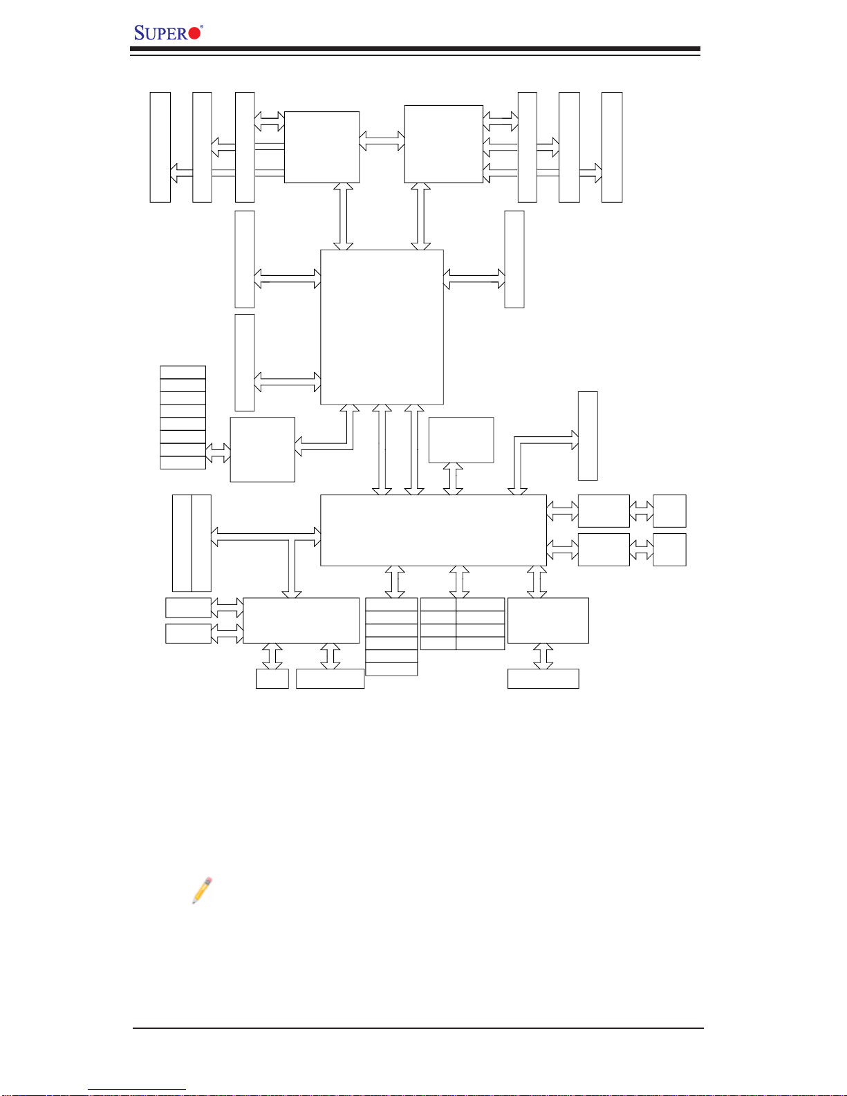
C
DDR3 DIMM
SAS #0
SAS #1
SAS #2
SAS #3
SAS #4
SAS #5
SAS #6
SAS #7
B
DDR3 DIMM
DDR3 DIMM
PCI-E x8 (Slot5)
PCI-E x16 (Slot6)
LSI 1068E
PCI 32bit_33MHz
A
Gen2
Gen2
CPU1
LGA1366
Port
x4
Ports
x8
Ports
Gen2
CSI
1
1,2
Intel 5500
7,8
ESI
3
Port
x4
DMI
Ports
CLIN
LGA1366
Port 0
9,10
CLINK
ICH10R
CPU2
Gen2
ATMEL
AT25DF321
SPI
D
x8
Ports 1-4
PCI-E x8 (Slo4)
Gen1
Port 5
Port 6
DDR3 DIMM
E
x4
x1
x1
F
DDR3 DIMM
PCI-E x8 (Slot3)
82574L
82574L
DDR3 DIMM
RJ45
RJ45
PCI32/33 (Slot1)
PCI32/33 (Slot2)
COM1
COM2
Note: This is a general block diagram. Please see the previous Motherboard Features pages for details on the features of each motherboard.
RJ45
BMC
VGA CONN
SATA
SATA #1
SATA #2
SATA #3
SATA #4
SATA #5
SATA #6
USB
Rear
Front
Front
Type A
USB #0/1
USB #2/3
USB #4/5
USB #6
Block Diagram of the 5500 Chipset
LPC
SIO
W83527DHG-P
PS2 KB/MS
1-8

Chapter 1: Introduction
1-2 Chipset Overview
Built upo n the f unct iona lit y and the c apa bilit y of th e 550 0 pl atf orm, t he X8DT L-3/
X8DTL-i/X8DTL-3F/X8DTL-iF motherboard provides the performance and feature set required for dual-processor-based high -end systems w ith confi guration
optimize d fo r H C P/Clu ste r syst em s an d inte ns i ve ap pl ication s. T h e 5 5 00 plat f o r m
cons ists of t he 55 00/ 56 00 Se ries (LGA 1366) proc ess or, the IOH -24D (I /O Hub),
and the IC H10R (South B ri dg e). With the I ntel Q uic kPat h Inte rc onn ec t (QPI) co n trolle r built in, the 55 00 platf orm is the fi rst dua l-proc essing plat form that of fers
the next generation point-to-point system interconnect interface, replacing the
curr ent Front Si de Bus Technol ogy, substa ntiall y enhan cing sy stem pe r for manc e
with inc reas ed band width a nd sca labili ty.
The IOH-24D connects to each processor through an independent QuickPath
Interconnect (QPI) link. Each link consists of 20 pairs of unidirectional differential
lanes fo r transm issio n and rec eivin g in additi on to a dif fere ntial for war ded cl ock.
A full-width QPI link pair provides 84 signals. Each processor supports two QuickPath links, on e going to t he othe r proc esso r and the ot her to the I OH -24D chi p.
The 5500 Platform supports PCI Express Gen2 lanes, peer-to-peer read and write
transactions. The ICH10R provides up to 6 PCI -Express por ts, six SATA ports
and 10 USB co nnec tion s.
In additi on, the 5 50 0 plat form a lso of fers a w ide ran ge of R AS (Reli abilit y, Availability and Serviceability) features. These features include memory interface ECC,
x4/x8 S ingle Devic e Data C orrec tion (SDD C), Cyclic Redund ancy Chec k (CRC),
parit y pr otect ion, o ut- of- ban d regi ster ac ce ss vi a SM Bus, m emor y m ir ror ing, an d
Hot-p lug supp or t on the P CI- Ex pres s Inter fac e.
Main Features of the 5500/5600* Series Processor and the
5500 Chipset
Four processor cores in each processor with 8MB shared cache among cores•
Two full-width Intel QuickPath interconnect links, up to 6.4 GT/s of data transfer •
rate in each direction
Virtualization Technology, Integrated Management Engine supported
•
Point-to-point cache coherent interconnect, Fast/narrow unidirectional links, and •
Concurrent bi-directional traffi c
Error detection via CRC and Error correction via Link level retry
•
1-9
X8DTL-3/X8DTL-i/X8DTL-3F/X8DTL-iF User's Manual
1-3 Special Features
Recovery from AC Power Loss
BIOS provides a setting for you to determine how the system will respond when
AC power is lost and then restored to the system. You can choose for the system
to remain powered off (in which case you must hit the power switch to turn it back
on) or for it to automatically return to a power- on state. See the Advanced BIOS
Setup section to change this setting. The default setting is Last State.
1-4 PC Health Monitoring
This section describes the PC health monitoring features of the X8DTL-3/X8DTL-i/
X8DTL-3F/X8DTL-iF. All have an onboard System Hardware Monitor chip that supports PC health monitoring. An onboard voltage monitor will scan these onboard
voltages continuously: CPU1 Vcore, CPU2 Vcore, CPU2 DIMM, CPU1 DIMM, 5V,
5VSB, 12V , -12V, 3.3Vcc, 3.3VSB, VBAT and Vtt. Once a voltage becomes unstable,
a warning is given or an error message is sent to the screen. Users can adjust the
voltage thresholds to defi ne the sensitivity of the voltage monitor.
Fan Status Monitor with Firmware Control
The PC health monitor can check the RPM status of the cooling fans. The onboard
CPU and chassis fans are controlled by Thermal Management via BIOS (under
Hardware Monitoring in the Advanced Setting).
Environmental Temperature Control
The thermal control sensor monitors the CPU temperature in real time and will turn
on the thermal control fan whenever the CPU temperature exceeds a user-defi ned
threshold. The overheat circuitry runs independently from the CPU. Once it detects
that the CPU temperature is too high, it will automatically turn on the thermal fan
control to prevent any overheat damage to the CPU. The onboard chassis thermal
circuitry can monitor the overall system temperature and alert users when the chassis temperature is too high.
Warning! To avoid possible system overheating, be sure to provide adequate airfl ow to the system.
System Resource Alert
This feature is availab le when used with S upero Doctor III in the Windows OS
environment or used with Supero Doctor II in Linux. Supero Doctor is used to
1-10

Chapter 1: Introduction
notif y the user of cer tain system events. For example, you can also confi gure
Supero Doctor to provide you with warnings when the system temperature, CPU
temperat ures, volt ages a nd fan spe eds go beyon d a pre- defi ned range.
1-5 ACPI Features
ACPI stands for Advanced Confi guration and Power Interface. The ACPI specifi ca-
tion defi nes a fl exible and abstract hardware interface that provides a standard
way to integrate power management features throughout a PC system, including
its hardware, operating system and application software. This enables the system
to automatically turn on and off peripherals such as CD-ROMs, network cards, hard
disk drives and printers.
In addition to enabling operating system-directed power management, ACPI
provides a generic system event mechanism for Plug and Play and an operating
system-independent interface for confi guration control. ACPI leverages the Plug
and Play BIOS data structures while providing a processor architecture-independent
implementation that is compatible with Windows XP, Windows 2003, Windows 2008
and Windows Vista Operating Systems.
Slow Blinking LED for Suspend-State Indicator
When the CPU goes into a suspend state, the chassis power LED will start blinking
to indicate that the CPU is in suspend mode. When the user presses any key, the
CPU will wake-up and the LED will automatically stop blinking and remain on.
Main Switch Override Mechanism
When an ATX power supply is used, the power button can function as a system
suspend button to make the system enter a SoftOff state. The monitor will be
suspended and the hard drive will spin down. Pressing the power button again
will cause the whole system to wake-up. During the SoftOff state, the ATX power
supply provides power to keep the required circuitry in the system "alive." In case
the system malfunctions and you want to turn off the power, just press and hold
the power button for 4 seconds. This option can be set in the Power section of the
BIOS Setup routine.
Wake-On-LAN (WOL)
Wake-On-LAN is defi ned as the ability of a management application to remotely
power up a computer that is powered off. Remote PC setup, up-dates and asset
tracking can occur after hours and on weekends so that daily LAN traffi c is kept to
a minimum and users are not interrupted. The motherboard has a 3-pin header
(WOL) to connect to the 3-pin header on a Network Interface Card (NIC) that has
1-11
X8DTL-3/X8DTL-i/X8DTL-3F/X8DTL-iF User's Manual
WOL capability. In addition, an onboard LAN controller can also support WOL
without any connection to the WOL header. The 3-pin WOL header is to be used
with a LAN add-on card only.
Note: Wake-On-LAN requires an ATX 2.01 (or above) compliant power
supply.
External Modem Ring-On
Wake-up events can be triggered by a device such as the external modem ringing
when the sy stem is in the Sof tOff state. N ote that external m odem ring- on can
only be us ed wit h an ATX 2.01 (or above) complia nt power sup ply.
1-6 Power Supply
As with all computer products, a stable power source is necessary for proper and
reliable operation. It is even more important for processors that have high CPU
clock rates.
The X8DTL-3/X8DTL-i/X8DTL-3F/X8DTL-iF can accommodate 24-pin ATX power
supplies. Although most power supplies generally meet the specifi cations required
by the CPU, some are inadequate. In addition, the two 12V 8-pin power connections
are also required to ensure adequate power supply to the system. Also your power
supply must supply 1.5A for the Ethernet ports.
Warning: To prevent damage to the power supply or motherboard, please
use a power supply that contains a 24-pin and two 8-pin power connectors.
Be sure to connect these connectors to the 24-pin (JPW1) and the two
8-pin (JPW2,JPW3) power connectors on the motherboard for adequate
power supply to your system. Failure in doing so will void the manufacturer
warranty on your power supply and motherboard.
It is strongly recommended that you use a high quality power supply that meets ATX
power supply Specifi cation 2.02 or above. It must also be SSI compliant (For more
information, please refer to the web site at http://www.ssiforum.org/). Additionally, in
areas where noisy power transmission is present, you may choose to install a line
fi lter to shield the computer from noise. It is recommended that you also install a
power surge protector to help avoid problems caused by power surges.
1-7 Super I/O
The Super I/O supports 360 K, 720 K, 1.2 M, 1.44 M or 2.88 M disk drives and data
transfer rates of 250 Kb/s, 500 Kb/s or 1 Mb/s. It also provides two high-speed,
16550 compatible serial communication ports (UARTs). Each UART includes a
16-byte send/receive FIFO, a programmable baud rate generator, complete modem
1-12

Chapter 1: Introduction
control capability and a processor interrupt system. Both UARTs provide legacy
speed with baud rate of up to 115.2 Kbps as well as an advanced speed with baud
rates of 250 K, 500 K, or 1 Mb/s, which support higher speed modems.
The Super I/O provides functions that comply with ACPI (Advanced Confi guration
and Power Interface), which includes support of legacy and ACPI power management through an SMI or SCI function pin. It also features auto power management
to reduce power consumption.
1-8 Overview of the Nuvoton WPCM450R Controller (For
X8DTL-3F/X8DTL-iF Only)
The Nuvoton WPCM450R Controller is a Baseboard Management Controller
(BMC) that supports the 2D/VGA-compatible Graphics Core with the PCI interface,
Virtual Media, and Keyboard/Video/Mouse Redirection (KVMR) modules. With
blade-oriented Super I/O capability built-in, the WPCM450R Controller is ideal for
legacy-reduced server platforms.
The WPCM450R interfaces with the host system via a PCI interface to communicate with the Graphics core. It supports USB 2.0 and 1.1 for remote keyboard/
mouse/virtual media emulation. It also provides LPC interface to control Super IO
functions. The WPCM450R is connected to the network via an external Ethernet
PHY module.
The WPCM450R communicates with onboard components via six SMBus interfaces, fan control, and Platform Environment Control Interface (PECI) buses.
Note: For more information on IPMI confi guration, please refer to the IPMI
user guide posted on our website @ http://www.supermicro.com/support/
manuals/
1-13

X8DTL-3/X8DTL-i/X8DTL-3F/X8DTL-iF User's Manual
Notes
1-14

Chapter 2: Installation
Chapter 2
Installation
2-1 Static-Sensitive Devices
Electrostatic Discharge (ESD) can damage electronic com ponents. T o prevent damage to your system board, it is important to handle it very carefully. The following
measures are generally suffi cient to protect your equipment from ESD.
Precautions
Use a grounded wrist strap designed to prevent static discharge.•
Touch a grounded metal object before removing the board from the antistatic •
bag.
Handle the board by its edges only; do not touch its components, peripheral
•
chips, memory modules or gold contacts.
When handling chips or modules, avoid touching their pins.
•
Put the motherboard and peripherals back into their antistatic bags when not •
in use.
For grounding purposes, make sure your computer chassis provides excellent
•
conductivity between the power supply, the case, the mounting fasteners and
the motherboard.
Use only the correct type of onboard CMOS battery as specifi ed by the
•
manufacturer. Do not install the onboard battery upside down to avoid possible
explosion.
Unpacking
The motherboar d is shipped i n a ntistati c pa ckaging to avoid static da mage. When
unpacking the board, make sure the person handling it is static protected.
2-1
X8DTL-3/X8DTL-i/X8DTL-3F/X8DTL-iF User's Manual
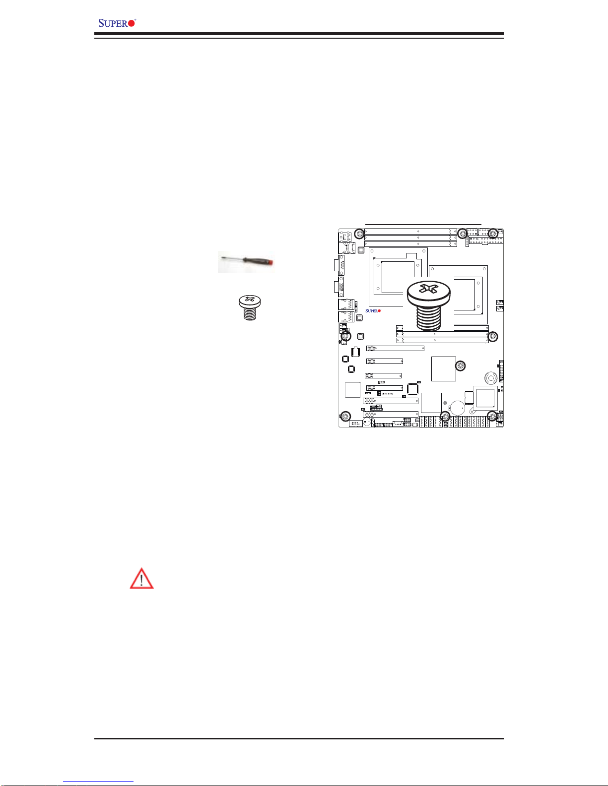
2-2 Motherboard Installation
All motherboards have standard mounting holes to fi t different types of chassis.
Make sure that the locations of all the mounting holes for both motherboard and
chassis match. Although a chassis may have both plastic and metal mounting
fasteners, metal ones are highly recommended because they ground the motherboard to the chassis. Make sure that the metal standoffs click in or are screwed in
tightly. Then use a screwdriver to secure the motherboard onto the motherboard
tray. Note: Some components are very close to the mounting holes. Please take
precautionary measures to prevent damage to these components when installing
the motherboard to the chassis.
Tools Needed
1. Phillips Screwdriver
Locations of Mounting Holes
2. Pan head #6 screws
X8DTL Series
Installation Instructions
Install the IO shield into the chassis. 1.
Locate the mounting holes on the moth-2.
erboard. Refer to the layout above for
mounting hole locations.
Locate the matching mounting holes on the chassis. Align the mounting holes 3.
on the motherboard against the mounting holes on the chassis.
Install standoffs in the chassis as needed.4.
Install the motherboard into the chassis carefully to avoid damage to mother-5.
board components.
Warning: To avoid damaging the motherboard and its components, please
do not apply any force greater than 8 lb/sq.in (8 lbs. per square inch) when
installing a screw into a mounting hole.
Rev. 2.01
Insert a Pan head #6 screw into a mounting hole on the motherboard and its 6.
matching mounting hole on the chassis, using a Phillips screwdriver.
Repeat Step 4 to insert #6 screws to all mounting holes.7.
Make sure that the motherboard is securely placed on the chassis.8.
2-2
2-3 Processor and Heatsink Installation
!
When handling the processor package, avoid placing direct pressure on
the label area of the fan.
Notes:
Always connect the power cord last and always remove it before adding, re-1.
moving or changing any hardware components. Make sure that you install the
processor into the CPU socket before you install the CPU heatsink.
Make sure to install the motherboard into the chassis before you install the 2.
CPU heatsink and heatsink fans.
When purchasing a motherboard without a 5500/5600 Series processor pre-3.
installed, make sure that the CPU socket plastic cap is in place, and none of
the CPU socket pins are bent; otherwise, contact the retailer immediately.
Chapter 2: Installation
Refer to the M B Features S ecti on for mo re deta ils on CPU s uppor t.4.
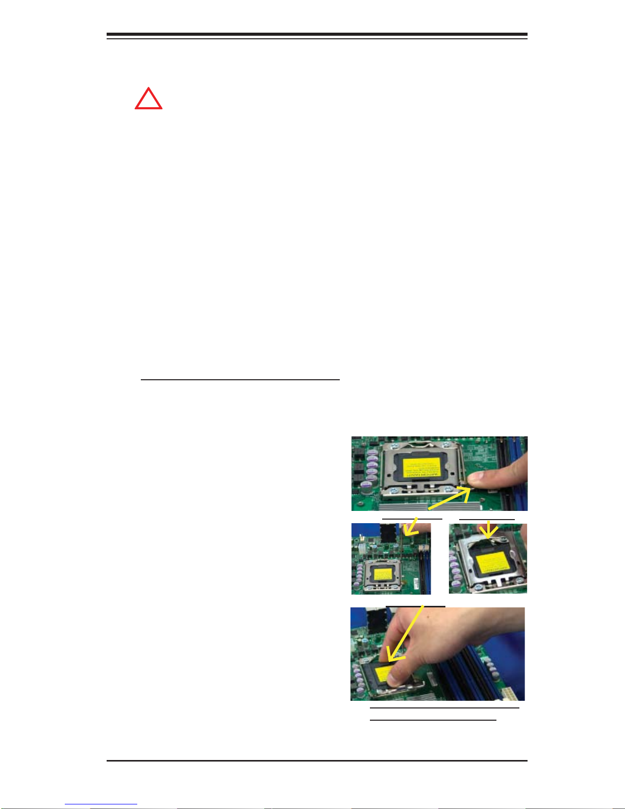
Installing an LGA 1366 Processor
Press the socket clip to release 1.
the load plate, which covers the
CPU socket, from its locking
position.
Gently lift the socket clip to 2.
open the load plate.
Hold the plastic cap at its north 3.
and south center edges to remove it from the CPU socket.
Socket Clip
Plastic Cap
Load Plate
Hold the north & south edges of
the plastic cap to remove it
2-3
X8DTL-3/X8DTL-i/X8DTL-3F/X8DTL-iF User's Manual
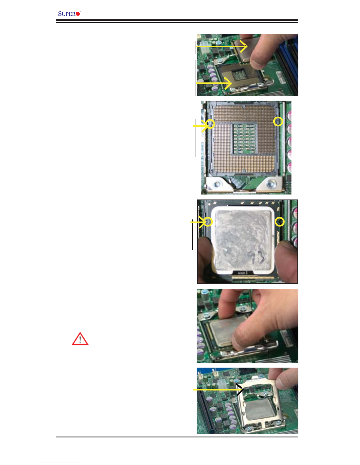
After removing the plastic cap, 1.
using your thumb and the index
fi nger, hold the CPU at the
CPU CPU SocketLoad Plate
north and south center edges.
Align the CPU key, the semi-2.
circle cutout, against the socket
key, the notch below the gold
color dot on the side of the
socket.
Once both the CPU and the 3.
socket are aligned, carefully
lower the CPU straight down
Socket Keys
into the socket. (Do not rub the
CPU against the surface of the
socket or its pins to avoid damaging the CPU or the socket.)
With the CPU inside the socket, 4.
inspect the four corners of the
CPU to make sure that the CPU
is properly installed.
Once the CPU is securely 5.
seated on the socket, lower the
CPU load plate to the socket.
Use your thumb to gently push 6.
the socket clip down to the clip
lock.
Warning: Please s ave the
plastic cap. The motherboard must be shipped
with the plastic cap properly ins tal led to p rotec t the
CPU socket pins. Shipment without the plastic
cap properly installed will
cause damage to the socket pins.
CPU Keys
2-4
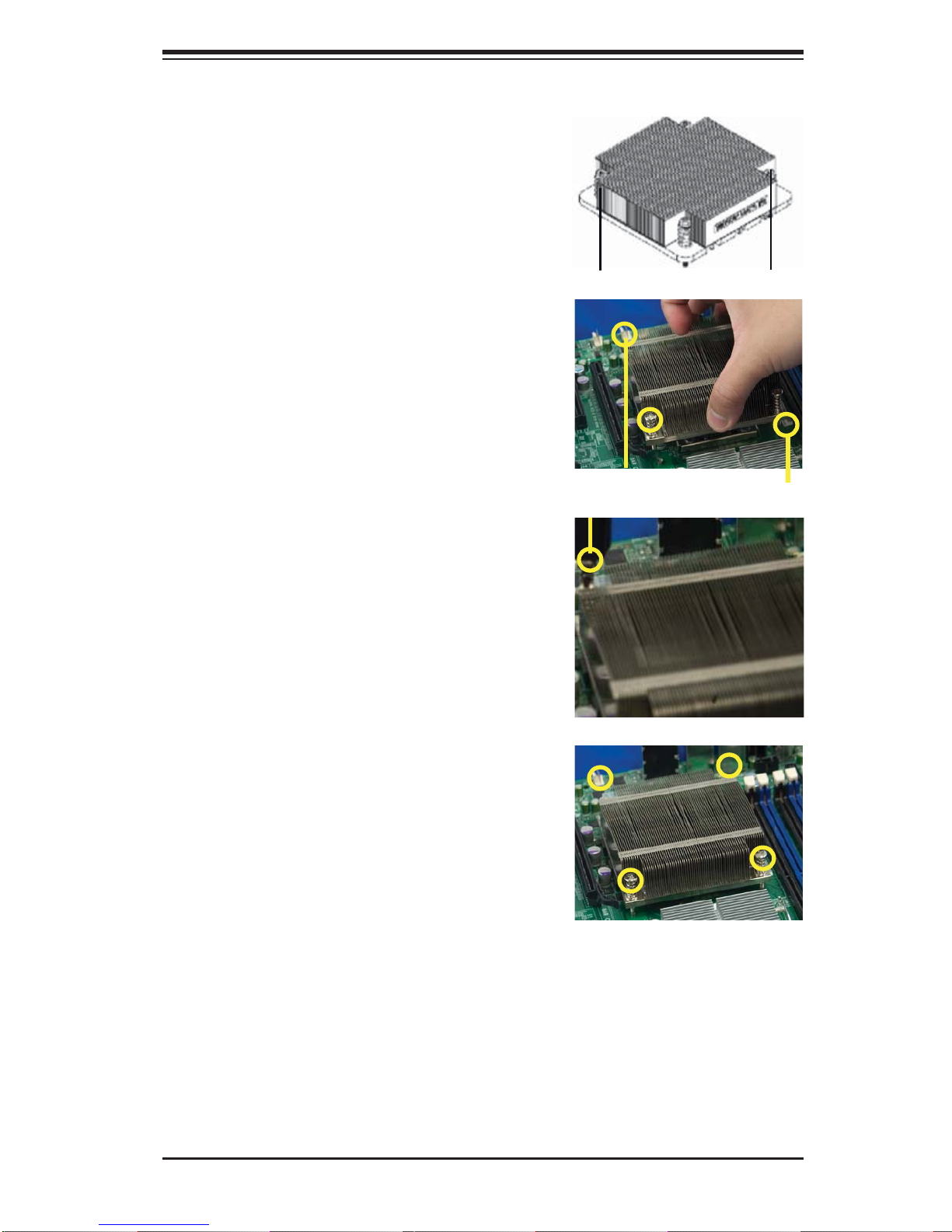
Installing a CPU Heatsink
Do not apply any thermal 1.
grease to the heatsink or the
CPU die because the required
amount has already been applied.
Chapter 2: Installation
Place the heatsink on top of the 2.
CPU so that the four mounting
holes are aligned with those on
the retention mechanism.
3. Install two diagonal screws (ie
the #1 and the #2 screws) and
tighten them until just snug (-do
not fully tighten the screws to
avoid possible damage to the
CPU.)
Screw#1
Screw#1
Install Screw#1
Screw#2
Screw#2
4. Finish the installation by fully
tightening all four screws.
2-5
X8DTL-3/X8DTL-i/X8DTL-3F/X8DTL-iF User's Manual
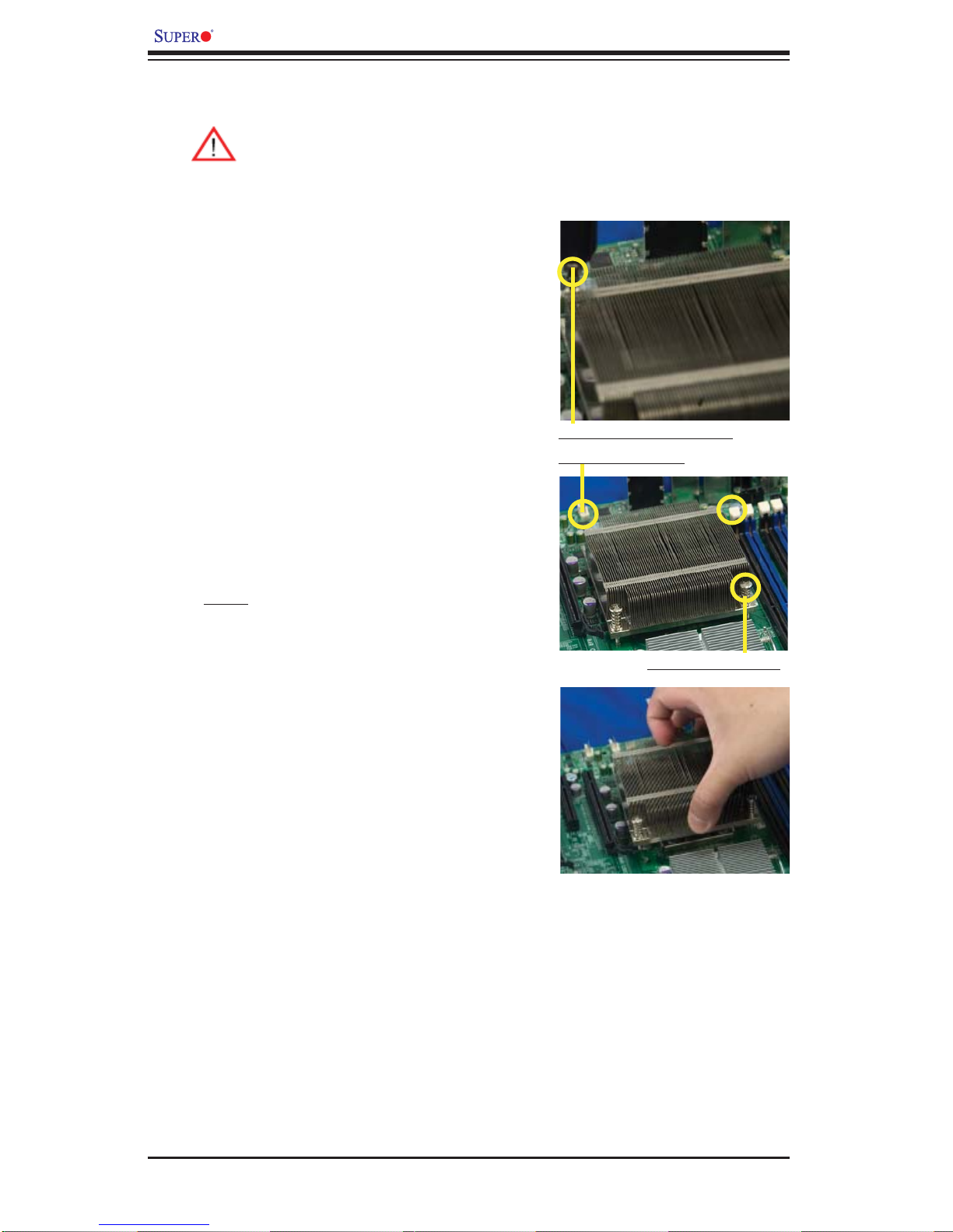
Removing the Heatsink
Warni ng: We do not recommend that the CPU or the heatsink be removed. However, if you do need to remove the heatsink, please follow
the inst ructions be low to uninstall th e heatsink and prevent da mage to
the CPU or ot her co mpone nts.
Unplug the power cord from the 1.
power supply.
Disconnect the heatsink fan 2.
wires from the CPU fan header.
Using a screwdriver, loosen and 3.
remove the heatsink screws
from the motherboard in the sequence as show in the picture
on the right.
Using a screwdriver to
remove Screw#1
Hold the heatsink as shown 4.
in the picture on the right and
gently wriggle the heatsink to
loosen it from the CPU. (Do not
use excessive force when wriggling the heatsink.)
Once the CPU is loosened, 5.
remove the heatsink from the
CPU socket.
To reinstall the CPU and the 6.
heatsink, clean the surface of
the CPU and the heatsink to get
rid of the old thermal grease.
Reapply the proper amount of
thermal grease on the surface
before reinstalling them on the
motherboard.
Remove Screw#2
2-6
Chapter 2: Installation
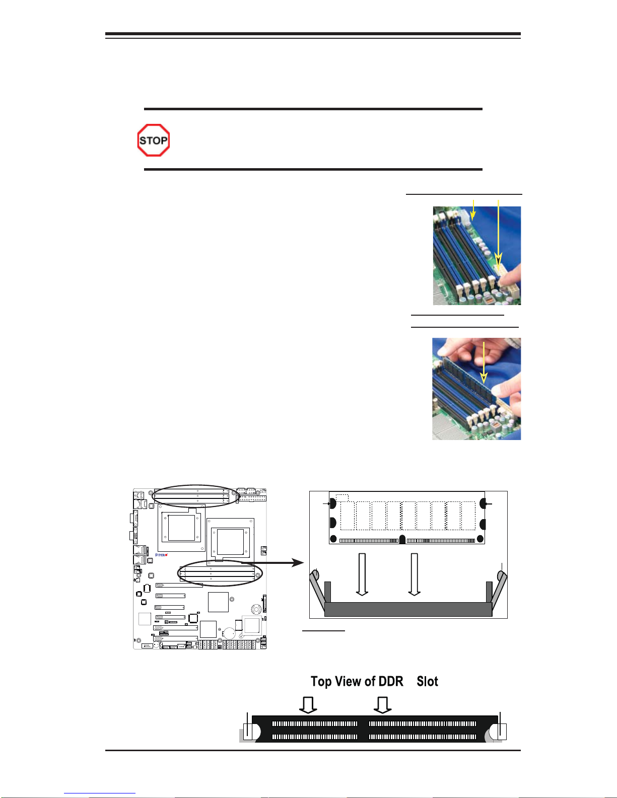
2-4 Installing and Removing the Memory Modules
Note: Check the S uper micro we b site for r ecom mende d memor y mo dules .
CAUTION
Exercise extreme care when installing or removing DIMM
module s to prevent a ny possi ble dam age.
Installing & Removing DIMMs
Insert the desired number of DIMMs into the memory 1.
slots, starting with P1-DIMM #1A. When populating
multiple DIMM modules within a channel, always start
with Bank1 fi rst. (For best performance, please use the
memory modules of the same type and same speed in
the same bank.)
Press down the release tabs on the ends of a memory 2.
slot. Insert each DIMM module vertically into its slot.
Pay attention to the notch along the bottom of the
module to prevent inserting the DIMM module incorrectly.
Gently press down on the DIMM module until it snaps 3.
into place in the slot. Repeat for all modules.
Reverse the steps above to remove the DIMM mod-4.
ules from the motherboard.
otch
DIMM DDR3
Press down the release tabs
Insert & press down a
DIMM module into the slot
Notch
X8DTL Series
Rev. 2.01
To Remove:
Use your thumbs
to gently push the
release tabs near both
ends of the module.
This should release it
from the slot.
Release Tab
Release
Tab
Note: Notch
should align
with the
receptive point
on the slot
Release
Tab
To Install : Insert module vertically and press
down unt il it sn aps in to plac e. Pay at tent ion to t he
align ment n otch at t he bot to m.
3
Release Tab
2-7
X8DTL-3/X8DTL-i/X8DTL-3F/X8DTL-iF User's Manual
Memory Support
The X8DTL-3/-i/-3F/iF supports up to 96 GB Registered ECC or up to 24 GB Unbuffered ECC/Non-ECC DDR3 1333 MHz/1066 MHz/800 MHz in six DIMMs.
Note: Memory Speed support depends on the type(s) of CPU(s) installed
on the motherboard.
DIMM Module Population Confi guration
For memor y to wor k pro perl y, follow the tab les be low for me mor y inst allati on:
Memory Population for Optimal Performance
-For a motherboard with One CPU (CPU1) installed
(To Populate P1-DIMM slots)
Branch 0 Branch 1 Branch 2
3 DIMMs P1-1A P1-2A P1-3A
Memory Population for Optimal Performance
-For a motherboard with One CPU (CPU2) installed
(To Populate P2-DIMM slots)
Branch 0 Branch 1 Branch 2
3 DIMMs P2-1A P2-2A P2-3A
Memory Population for Optimal Performance
-For a motherboard with Two CPUs installed
CPU1 (To populate P1-
DIMMs)
Branch 0 Branch 1 Branch 2 Branch 0 Branch 1 Branch 2
6 DIMMs P1-1A P1-2A P1-3A P2-1A P2-2A P2-3A
CPU2 (To populate P2-
DIMMs)
Memory Support for a Motherboard w/ the 5500 Processors Installed
Memory Population Table
DIMM
Slots per
Channel
1 1 Reg. DDR3 ECC 800,1066,1333 SR, DR
1 1 Reg. DDR3 ECC 800,1066 QR
DIMM
Slots per
Channel
1 1 Unb. DDR3 ECC/
DIMMs
Populated
per Channel
DIMMs
Populated
per Channel
DIMM Type (Reg.=
Registered)
Unbuffered DIMM (UDIMM) Population Table
DIMM Type
(Unb.= Unbuffered)
Non-ECC
Speeds (in MHz) Ranks per DIMM
Speeds (in MHz) Ranks per DIMM
800,1066, 1333 SR or DR
(any combination;
SR=Single Rank,
DR=Dual Rank,
QR=Quad Rank)
(SR=Single Rank,
DR=Dual Rank,
QR=Quad Rank)
2-8
 Loading...