

Supero SC846E26-R1200B, SC846A-R1200B, SC826E16-R1200B, SC846E1-R1200B, SC846BE16-R920B User Manual
...Page 1
IceBreaker 4924
Technical Guide
Rev. 1.0
PENGUIN
COMPUTING
www.penguincomputing.com | 1-888-PENGUIN (736-4846) | twitter:@PenguinHPC
Page 2
SC846 CHASSIS SERIES
USER’S MANUAL
2.0a
SUPER
®
SC846TQ-R1200B
SC846E26-R1200B SC826E16-R1200B
SC846E1-R1200B SC846A-R1200B
SC846BE16-R920B SC846BE26-R920B
SC846BA16-R920B SC846BA26-R920B
SC846TQ-R900B SC846E1-R900B
SC846E2-R900B SC846E1-R710B
Page 3

SC846 Chassis Manual
Manual Revision 2.0a Release
Date: February 19, 2013
Unless you request and receive written permission from Super Micro Computer, Inc., you may not
copy any part of this document.
Information in this document is subject to change without notice. Other products and companies
referred to herein are trademarks or registered trademarks of their respective companies or mark
holders.
Copyright © 2013 by Super Micro Computer, Inc.
All rights reserved.
Printed in the United States of America
ii
The information in this User’s Manual has been carefully reviewed and is believed to be accurate.
The vendor assumes no responsibility for any inaccuracies that may be contained in this document,
makes no commitment to update or to keep current the information in this manual, or to notify any
person or organization of the updates. Please Note: For the most up-to-date version of this
manual, please see our web site at www.supermicro.com.
Super Micro Computer, Inc. ("Supermicro") reserves the right to make changes to the product
described in this manual at any time and without notice. This product, including software and
documentation, is the property of Supermicro and/or its licensors, and is supplied only under a
license. Any use or reproduction of this product is not allowed, except as expressly permitted by
the terms of said license.
IN NO EVENT WILL SUPERMICRO BE LIABLE FOR DIRECT, INDIRECT, SPECIAL, INCIDENTAL,
SPECULATIVE OR CONSEQUENTIAL DAMAGES ARISING FROM THE USE OR INABILITY TO
USE THIS PRODUCT OR DOCUMENTATION, EVEN IF ADVISED OF THE POSSIBILITY OF
SUCH DAMAGES. IN PARTICULAR, SUPERMICRO SHALL NOT HAVE LIABILITY FOR ANY
HARDWARE, SOFTWARE, OR DATA STORED OR USED WITH THE PRODUCT, INCLUDING THE
COSTS OF REPAIRING, REPLACING, INTEGRATING, INSTALLING OR RECOVERING SUCH
HARDWARE, SOFTWARE, OR DATA.
Any disputes arising between manufacturer and customer shall be governed by the laws of Santa
Clara County in the State of California, USA. The State of California, County of Santa Clara shall
be the exclusive venue for the resolution of any such disputes. Super Micro's total liability for all
claims will not exceed the price paid for the hardware product.
California Best Management Practices Regulations for Perchlorate Materials: This Perchlorate
warning applies only to products containing CR (Manganese Dioxide) Lithium coin cells. “Perchlorate
Material-special handling may apply. See
www.dtsc.ca.gov/hazardouswaste/perchlorate”
WARNING: Handling of lead solder materials used in this
product may expose you to lead, a chemical known to
the State of California to cause birth defects and other
reproductive harm.
Page 4

iii
Preface
Preface
About This Manual
This manual is written for professional system integrators and PC technicians. It
provides information for the installation and use of the SC846 chassis. Installation
and maintenance should be performed by experienced technicians only.
This manual lists compatible parts available when this document was published. Always refer to the our Web site for updates on supported parts and configurations.
Page 5

SC846 Chassis Manual
iv
Manual Organization
Chapter 1 Introduction
The first chapter provides a checklist of the main components included with this
chassis and describes the main features of the SC846 chassis. This chapter also
includes contact information.
Chapter 2 System Safety
This chapter lists warnings, precautions, and system safety. It recommended that
you thoroughly familiarize yourself installing and servicing this chassis safety precautions.
Chapter 3 Chassis Components
Refer here for details on this chassis model including the fans, bays, airflow shields,
and other components.
Chapter 4 System Interface
Refer to this chapter for details on the system interface, which includes the functions
and information provided by the control panel on the chassis as well as other LEDs
located throughout the system.
Chapter 5 Chassis Setup and Maintenance
Follow the procedures given in this chapter when installing, removing,
or
reconfiguring your chassis.
Chapter 6 Rack Installation
Refer to this chapter for detailed information on chassis rack installation. You should
follow the procedures given in this chapter when installing, removing or
reconfiguring your chassis into a rack environment.
Page 6

Appendices
This section lists compatible cables, power supply specifications, and compatible
backplanes. Not all compatible backplanes are listed. Refer to our Web site for the
latest compatible backplane information.
Appendix A Cables and Hardware
This section provides information on cabling, and other hardware which is compatible with your chassis. For complete information on supported cables and hardware,
refer to the Supermico Web site at www.supermicro.com.
Appendix B Power Supply Specifications
This chapter lists the specifications for the power supply provided with your chassis. For additional information, refer to the Supermicro website at www.supermicro.
com.
Appendix C SAS-846TQ Backplane Specifications
This section contains details specific to the SAS-846TQ backplane for the SC846TQ
chassis. Additional information can be found on the Supermicro Web site at www.
supermicro.com.
Appendix D SAS-846EL Backplane Specifications
Refer to this chapter for detailed specifications on the SAS-846EL backplane for the
SC846-EL chassis systems. Additional information can be found on the Supermicro
Web site at www.supermicro.com.
Appendix E SAS2-846EL Backplane Specifications
This section contains detailed specifications on the SAS2-846EL backplane for the
SC846-EL chassis system. Additional information can be found on the Supermicro
Web site at www.supermicro.com.
Appendix F SC846B Chassis Specifications
This section provides information specific to the SC846B model chassis. Additional
information can be found on the Supermicro Web site at www.supermicro.com.
v
Preface
Page 7

SC846 Chassis Manual
Chapter 1 Introduction
1Overview 1-1
2Shipping Li
st 1-1
1-3 Where to get Replacement Components 1-2
1-4 Contacting Supermicro 1-3
1-5 Returning Merchandise for Service 1-4
Chapter 2 Standardized Warning Statements for AC Systems
2-1 About Standardized Warning Statements 2-1
Warning Definition 2-1
Installation Instructions 2-4
Circuit Breaker 2-5
Power Disconnection Warning 2-6
Equipment Installation 2-8
Restricted Area 2-9
Battery Handling 2-10
Redundant Power Supplies 2-12
Backplane Voltage 2-13
Comply with Local and National Electrical Codes 2-14
Product Disposal 2-15
Hot Swap Fan Warning 2-16
Power Cable and AC Adapter 2-18
Chapter 3 System Interface
3-1 Overview 3-1
3-2 Control Panel Buttons 3-2
3-3 Control Panel LEDs 3-2
3-4 Drive Carrier LEDs 3-4
SAS/SATA Drives 3-4
SCSI Drives 3-4
Chapter 4 Chassis Setup and Maintenance
4-1 Overview 4-1
4-2 Removing the Chassis Cover 4-2
4-3 Installing Hard Drives 4-3
4-4 Installing the Motherboard
4
-6
I/O Shield 4-6
vi
Table of Contents
Page 8

vii
Preface
Permanent and
Optional Standoffs 4-7
Expansion Card Setup 4-9
4-5 Installing the Air Shroud 4-10
4-6 Checking the Server's Airflow 4-11
4-7 System Fans 4-12
4-8 Power Supply 4-14
4-9 Changing the Power Distributor 4-17
4-10 Changing the CD-ROM or DVD-ROM and HDD Trays 4-19
4-11 Accessing the Backplane 4-22
Chapter 5 Rack Installation
5-1 Overview 5-1
5-2 Unpacking the System 5-1
5-3 Preparing for Setup 5-1
Choosing a Setup Location 5-1
5-4 Warnings and Precautions 5-2
Rack Precautions 5-2
General Server Precautions 5-2
Rack Mounting Considerations 5-3
Ambient Operating Temperature 5-3
Reduced Airflow 5-3
Mechanical Loading 5-3
Circuit Overloading 5-3
Reliable Ground 5-3
5-6 Rack Mounting Instructions 5-4
Identifying the Sections of the Rack Rails 5-4
Locking Tabs 5-5
Releasing the Inner Rail 5-5
Installing The Inner Rails on the Chassis 5-6
Installing the Outer Rails on the Rack 5-
7
S
tandard Chassis Installation 5-8
Optional Quick Installation Method 5-9
Appendix A SC846 Cables and H ardw are
Appendix B SC846 Power Supply Specifications
Appendix C SAS-846TQ Backplane Specifications
Appendix D SAS-846EL Backplane Specifications
Appendix E SAS2-846EL Backplane Specifications
Appendix F SC846B Chassis Specifications
Page 9

SC846 Chassis Manual
viii
Notes
Page 10
Chapter 1: Introduction
Chapter 1
Introduction
1 Overview
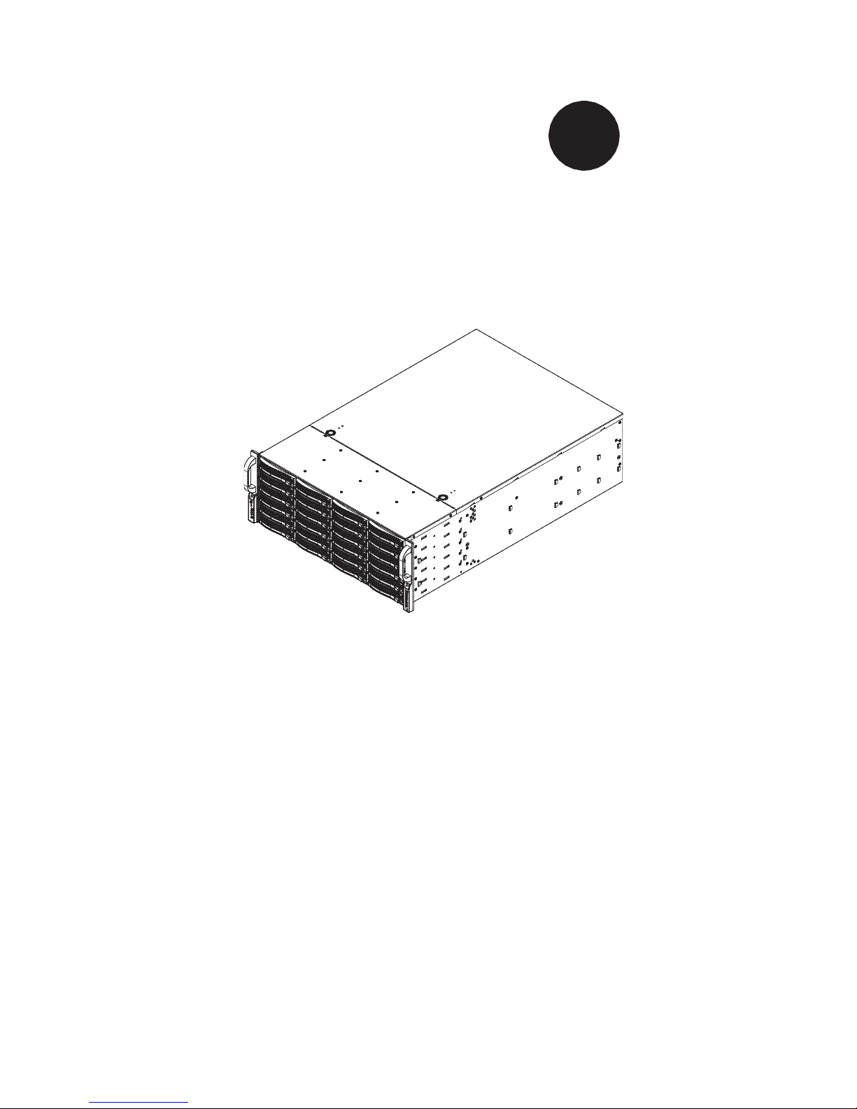
Supermicro’s SC846 4U chassis features a unique and highly optimized design.
The chassis is equipped with redundant high-efficiency power supplies. Highperformance fans provide ample optimized cooling and twenty-four hot-swappable
drive bays offer maximum storage capacity.
2 Shipping List
Visit www.supermicro.com for the latest shipping lists for your chassis model.
Note: A complete list of safety warnimgs is provided on the Supermicro web site at
http://www.supermicro.com/about/policies/safety_information.cfm
1-1
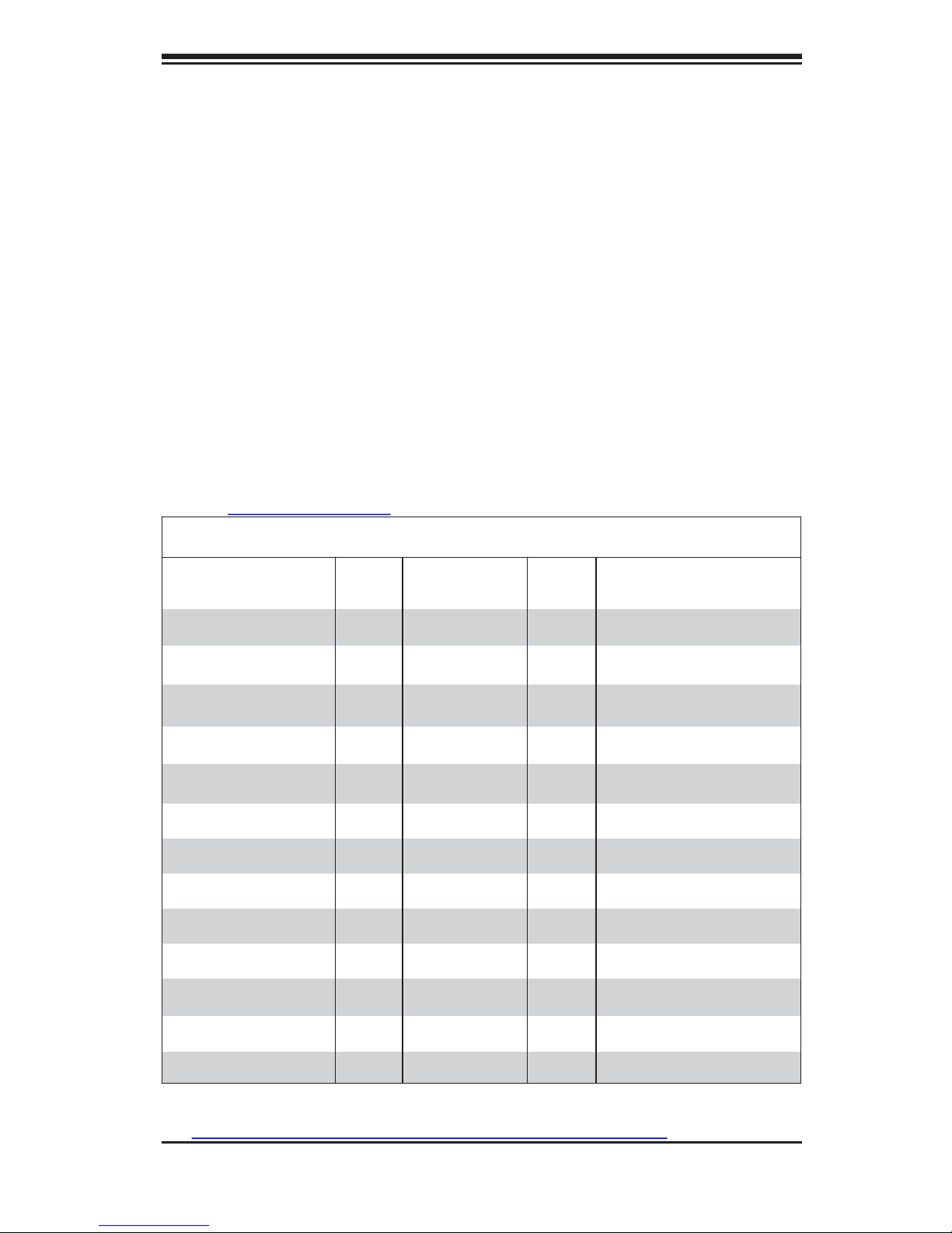
SC846 Chassis
Model CPU HDD PCI
Slots
Redundant Power
Supplies
SC846E16-R1200B
DP/UP 24x SAS/SATA 7x FF 1200W (Gold Level)
SC846E26-R1200B
DP/UP 24x SAS/SATA 7x FF 1200W (Gold Level)
SC846TQ-R1200B
DP/UP 24x SAS/SATA 7x FF 1200W (Gold Level)
SC846E1-R1200B
DP/UP 24x SAS/SATA 7x FF 1200W (Gold Level)
SC846A-R1200B
DP/UP 24x SAS/SATA 7x FF 1200W (Gold Level)
SC846BE26-R920B
DP/UP 24x SAS/SATA 7x FF 920W
SC846BE16-R920B
DP/UP 24x SAS/SATA 7x FF 920W
SC846BA26-R920B
DP/UP 24x SAS/SATA 7x FF 920W
SC846BA16-R920B
DP/UP 24x SAS/SATA 7x FF 920W
SC846TQ-R900B
DP/UP 24x SAS/SATA 7x FF 900W
SC846E1-R900B
DP/UP 24x SAS/SATA 7x FF 900W
SC846E2-R900B
DP/UP 24x SAS/SATA 7x FF 900W
SC846E1-R710B
DP/UP 24x SAS/SATA 7x FF 710W
Page 11

SC846 Chassis Manual
1-3 Where to get Replacement Components
Though not frequently, you may need replacement parts for your system. To ensure the highest level of professional service and technical support, we strongly
recommend purchasing exclusively from our Supermicro Authorized Distributors/
System Integrators/Resellers. A list of Supermicro Authorized Distributors/System
Integrators/Resellers can be found at: http://www.supermicro.com.
Click the Where
to Buy link.
1-2
Page 12

1-3
Chapter 1: Introduction
1-4 Contacting Supermicro
Headquarters
Address: Super Micro Computer, Inc.
980 Rock Ave.
San Jose, CA 95131 U.S.A.
Tel: +1 (408) 503-8000
Fax: +1 (408) 503-8008
Email: marketing@supermicro.com
(General Information)
support@supermicro.com (Technical Support)
Web Site: www.supermicro.com
Europe
Address: Super Micro Computer B.V.
Het Sterrenbeeld 28, 5215 ML
's-Hertogenbosch, The Netherlands
Tel: +31 (0) 73-6400390
Fax: +31 (0) 73-6416525
Email: sales@supermicro.nl
(General Information)
support@supermicro.nl (Technical Support)
rma@supermicro.nl (Customer Support)
Asia-Pacific
Address: Super Micro Computer, Inc.
4F, No. 232-1, Liancheng Rd
Chung-Ho Dist., New Taipei City 235
Taiwan
Tel: +886-(2) 8226-3990
Fax: +886-(2) 8226-3991
Web Site: www.supermicro.com.tw
Technical Support:
Email: support@supermicro.com.tw
Tel: +886-(2)-8226-3990
Page 13

SC846 Chassis Manual
1-5 Returning Merchandise for Service
A receipt or copy of your invoice marked with the date of purchase is required before
any warranty service will be rendered. You can obtain service by calling your vendor
for a Returned Merchandise Authorization (RMA) number. When returning to the
manufacturer, the RMA number should be prominently displayed on the outside of
the shipping carton, and mailed prepaid or hand-carried. Shipping and
handling charges will be applied for all orders that must be mailed when service is
complete.
For faster service, RMA authorizations may be requested online (http://www.
supermicro.com/support/rma/).
Whenever possible, repack the chassis in the original Supermicro carton, using the
original packaging material. If these are no longer available, be sure to pack the
chassis securely, using packaging material to surround the chassis so that it does
not shift within the carton and become damaged during shipping.
This warranty only covers normal consumer use and does not cover damages incurred in shipping or from failure due to the alteration, misuse, abuse or improper
maintenance of products.
During the warranty period, contact your distributor first for any product problems.
1-4
Page 14
2-1
Chapter 2: Warning Statements for AC Systems
Chapter 2
Standardized Warning Statements for AC Systems
2-1 About Standardized Warning Statements
The following statements are industry standard warnings, provided to warn the user
of situations which have the potential for bodily injury. Should you have questions
or experience difficulty, contact Supermicro's Technical Support department
for assistance. Only certified technicians should attempt to install or configure
components.
Read this appendix in its entirety before installing or configuring components in the
Supermicro chassis.
These warnings may also be found on our web site at http://www.supermicro.com/
about/policies/safety_information.cfm.
Warning Definition
Warning!
This warning symbol means danger. You are in a situation that could cause bodily
injury. Before you work on any equipment, be aware of the hazards involved with
electrical circuitry and be familiar with standard practices for preventing accidents.
警告の定義 この警告サインは危険を
意味します。
人身事故につながる可能性がありますので、いずれの機器でも動作させる前に、
電気回路に含まれる危険性に注意して、標準的な事故防止策に精通して下さい。
此警告符号代表危险。
您正处于可能受到严重伤害的工作环境中。在您使用设备开始工作之前,必须充分
意识到触电的危险,并熟练掌握防止事故发生的标准工作程序。请根据每项警告结
尾的声明号码找到此设备的安全性警告说明的翻译文本。
此警告符號代表危險。
您正處於可能身體可能會受損傷的工作環境中。在您使用任何設備之前,請注意觸
電的危險,並且要熟悉預防事故發生的標準工作程序。請依照每一注意事項後的號
碼找到相關的翻譯說明內容。
Page 15
2-2
xxx Chassis User's Manual
Warnung
WICHTIGE SICHERHEITSHINWEISE
Dieses Warnsymbol bedeutet Gefahr. Sie befinden sich in einer Situation, die zu
Verletzungen führen kann. Machen Sie sich vor der Arbeit mit Geräten mit den
Gefahren elektrischer Schaltungen und den üblichen Verfahren zur Vorbeugung
vor Unfällen vertraut. Suchen Sie mit der am Ende jeder Warnung angegebenen
Anweisungsnummer nach der jeweiligen Übersetzung in den
übersetzten Sicherheitshinweisen, die zusammen mit diesem Gerät ausgeliefert
wurden.
BEWAHREN SIE DIESE HINWEISE GUT AUF.
INSTRUCCIONES IMPORTANTES DE SEGURIDAD
Este símbolo de aviso indica peligro. Existe riesgo para su integridad física. Antes
de manipular cualquier equipo, considere los riesgos de la corriente eléctrica y
familiarícese con los procedimientos estándar de prevención de accidentes. Al
final de cada advertencia encontrará el número que le ayudará a encontrar el texto
traducido en el apartado de traducciones que acompaña a este dispositivo.
GUARDE ESTAS INSTRUCCIONES.
IMPORTANTES INFORMATIONS DE SÉCURITÉ
Ce symbole d'avertissement indique un danger.
Vous vous trouvez dans une
situation pouvant entraîner des blessures ou des dommages corporels. Avant
de travailler sur un équipement, soyez conscient des dangers liés aux circuits
électriques et familiarisez-vous avec les procédures couramment utilisées pour
éviter les accidents. Pour prendre connaissance des traductions des avertissements
figurant dans les consignes de sécurité traduites qui accompagnent cet appareil,
référez-vous au numéro de l'instruction situé à la fin de chaque avertissement.
CONSERVEZ CES INFORMATIONS.
Page 16

2-3
Warning Statements for AC Systems
안전을 위한 주의사항
경고!
이 경고 기호는 위험이 있음을 알려 줍니다. 작업자의 신체에 부상을 야기 할 수
있는 상태에 있게 됩니다. 모든 장비에 대한 작업을 수행하기 전에 전기회로와
관련된 위험요소들을 확인하시고 사전에 사고를 방지할 수 있도록 표준 작업절
차를 준수해 주시기 바랍니다.
해당 번역문을 찾기 위해 각 경고의 마지막 부분에 제공된 경고문 번호를
참조하십시오
BELANGRIJKE VEILIGHEIDSINSTRUCTIES
Dit waarschuwings symbool betekent gevaar. U verkeert in een situatie die
lichamelijk letsel kan veroorzaken. Voordat u aan enige apparatuur gaat werken,
dient u zich bewust te zijn van de bij een elektrische installatie betrokken risico's
en dient u op de hoogte te zijn van de standaard procedures om ongelukken te
voorkomen. Gebruik de nummers aan het eind van elke waarschuwing om deze te
herleiden naar de desbetreffende locatie.
BEWAAR DEZE INSTRUCTIES
Page 17
2-4
xxx Chassis User's Manual
Installation Instructions
Warning!
Read the installation instructions before connecting the system to the power source.
設置手順書
システムを電源に接続する前に、設置手順書をお読み下さい。
警告 将此系统连接电源前,请先阅读安装
说明。
警告 將系統與電源連接前,請先閱讀安裝
說明。
Warnung
Vor dem Anschließen des Systems an die Stromquelle die Installationsanweisungen
lesen.
¡Advertencia!
Lea las instrucciones de instalación antes de conectar el sistema a la red de
alimentación.
Attention
Avant de brancher le système sur la source d'alimentation, consulter les directives
d'installation.
시스템을 전원에 연결하기 전에 설치 안내를 읽어주십시오.
Waarschuwing
Raadpleeg de installatie-instructies voordat u het systeem op de voedingsbron
aansluit.
Page 18
2-5
Chapter 2: Warning Statements for AC Systems
Circuit Breaker
Warning!
This product relies on the building's installation for short-circuit (overcurrent)
protection. Ensure that the protective device is rated not greater than: 250 V, 20 A.
サーキット・ブレーカー
この製品は、短絡(過電流)保護装置がある建物での設置を前提としています
。 保護装置の定格が250 V、20 Aを超えないことを確認下さい。
警告 此产品的短路(过载电流)保护由建筑物的供电系统提供,确保短路保护设备的
额定电 流不大于250V,20A。
警告 此產品的短路(過載電流)保護由建築物的供電系統提供,確保短路保護設備的
額定電 流不大於250V,20A。
Warnung
Dieses Produkt ist darauf angewiesen, dass im Gebäude ein Kurzschluss-
bzw. Überstromschutz installiert ist. Stellen Sie sicher, dass der Nennwert der
Schutzvorrichtung nicht mehr als: 250 V, 20 A beträgt.
¡Advertencia!
Este equipo utiliza el sistema de protección contra cortocircuitos (o sobrecorrientes)
del edificio. Asegúrese de que el dispositivo de protección no sea superior a:
250 V, 20 A.
Attention
Pour ce qui est de la protection contre les courts-circuits (surtension), ce produit
dépend de l'installation électrique du local.
Vérifiez que le courant nominal du
dispositif de protection n'est pas supérieur à :250 V, 20 A.
Page 19
2-6
xxx Chassis User's Manual
경고!
이 제품은 전원의 단락(과전류)방지에 대해서 전적으로 건물의 관련 설비에 의
존합니다. 보호장치의 정격이 반드시 250V(볼트), 20A(암페어)를 초과하지
않도록 해야 합니다.
Waarschuwing
Dit product is afhankelijk van de kortsluitbeveiliging (overspanning) van
uw electrische installatie. Controleer of het beveiligde aparaat niet groter
gedimensioneerd is dan 220V, 20A.
Power Disconnection Warning
Warning!
The system must be disconnected from all sources of power and the power cord
removed from the power supply module(s) before accessing the chassis interior to
install or remove system components.
電源切断の警告
システムコンポーネントの取り付けまたは取り外しのために、シャーシー内部にアクセス す
るには、
システムの電源はすべてのソースから切断され、電源コードは電源モジュールから取り
外す必要があります。
警告 在你打开机箱并安装或移除内部器件前,必须将系统完全断电,并移除电
源线。
警告 在您打開機殼安裝或移除內部元件前,必須將系統完全斷電,並移除電
源線。 Warnung
Das System mu
ss von allen Quellen der Energie und vom Netzanschlusskabel
getrennt sein, das von den Spg.Versorgungsteilmodulen entfernt wird, bevor
es auf den Chassisinnenraum zurückgreift, um Systemsbestandteile anzubringen
oder zu entfernen.
Page 20
2-7
Chapter 2: Warning Statements for AC Systems
¡Advertencia!
El sistema debe ser disconnected de todas las fuentes de energía y del
cable eléctrico quitado de los módulos de fuente de alimentación antes de tener
acceso el interior del chasis para instalar o para quitar componentes de sistema.
Attention
Le système doit être débranché de toutes les sources de puissance ainsi que de
son cordon d'alimentation secteur avant d'accéder à l'intérieur du chassis pour
installer ou enlever des composants de systéme.
경고!
시스템에 부품들을 장착하거나 제거하기 위해서는 섀시 내부에 접근하기 전에 반
드시 전원 공급장치로부터 연결되어있는 모든 전원과 전기코드를 분리해주어야
합니다.
Waarschuwing
Voordat u toegang neemt tot het binnenwerk van de behuizing voor het installeren
of verwijderen van systeem onderdelen, dient u alle spanningsbronnen en
alle stroomkabels aangesloten op de voeding(en) van de behuizing te
verwijderen
Page 21
경고!
훈련을 받고 공인된 기술자만이 이 장비의 설치, 교체 또는 서비스를 수행할 수
있습니다.
2-8
xxx Chassis User's Manual
Equipment Installation
Warning!
Only trained and qualified personnel should be allowed to install, replace, or service
this equipment.
機器の設置
トレーニングを受け認定された人だけがこの装置の設置、交換、またはサービスを許可
されています。
警告 只有经过培训且具有资格的人员才能进行此设备的安装、更换和
维修。
警告 只有經過受訓且具資格人員才可安裝、更換與維修此
設備。
Warnung
Das Installieren, Ersetzen oder Bedienen dieser Ausrüstung sollte nur geschultem,
qualifiziertem Personal gestattet werden.
¡Advertencia!
Solamente el personal calificado debe instalar, reemplazar o utilizar este equipo.
Attention
Il est vivement recommandé de confier l'installation, le remplacement et la
maintenance de ces équipements à des personnels qualifiés et expérimentés.
Page 22
Chapter 2: Warning Statements for AC Systems
Waarschuwing
Deze apparatuur mag alleen worden geïnstalleerd, vervangen of hersteld door
geschoold en gekwalificeerd personeel.
Restricted Area
Warning!
This unit is intended for installation in restricted access areas. A restricted access
area can be accessed only through the use of a special tool, lock and key, or
other means of security. (This warning does not apply to workstations).
アクセス制限区域 このユニットは、アクセス制限区域に設置されることを想定しています。
アクセス制限区域は、特別なツール、鍵と錠前、その他のセキュリティの手段を用いての
み出入りが可能です。
警告 此部件应安装在限制进出的场所,限制进出的场所指只能通过使用特殊工具
、锁和 钥匙或其它安全手段进出的场所。
警告 此裝置僅限安裝於進出管制區域,進出管制區域係指僅能以特殊工具、鎖頭
及鑰匙 或其他安全方式才能進入的區域。
Warnung
Diese Einheit ist zur Installation in Bereichen mit beschränktem Zutritt vorgesehen.
Der Zutritt zu derartigen Bereichen ist nur mit einem Spezialwerkzeug, Schloss und
Schlüssel oder einer sonstigen Sicherheitsvorkehrung möglich.
¡Advertencia!
Esta unidad ha sido diseñada para instalación en áreas de acceso
restringido. Sólo puede obtenerse acceso a una de estas áreas mediante la
utilización de una h
erramienta especial, cerradura con llave u otro medio de
seguridad.
Attention
Cet appareil doit être installée dans des zones d'accès réservés. L'accès à
une zone d'accès réservé n'est possible qu'en utilisant un outil spécial, un
mécanisme de verrouillage et une clé, ou tout autre moyen de sécurité.
2-9
Page 23
xxx Chassis User's Manual
경고!
이 장치는 접근이 제한된 구역에 설치하도록 되어있습니다. 특수도구, 잠금 장치 및
키, 또는 기타 보안 수단을 통해서만 접근 제한 구역에 들어갈 수 있습니다.
Waarschuwing
Dit apparaat is bedoeld voor installatie in gebieden met een beperkte
toegang. Toegang tot dergelijke gebieden kunnen alleen verkregen worden door
gebruik te maken van speciaal gereedschap, slot en sleutel of andere
veiligheidsmaatregelen.
Battery Handling
Warning!
There is the danger of explosion if the battery is replaced incorrectly. Replace the
battery only with the same or equivalent type recommended by the manufacturer.
Dispose of used batteries according to the manufacturer's instructions
電池の取り扱い
電池交換が正しく行われなかった場合、破裂の危険性があります。交換する電池はメ
ー カーが推奨する型、または同等のものを使用下さい。使用済電池は製造元の指示に
従 って処分して下さい。
警告 电池更换不当会有爆炸危险。请只使用同类电池或制造商推荐的功能相当的
电池更 换原有电池。请按制造商的说明处理废旧电池。
警告 電池更換不當會有爆炸危險。請使用製造商建議之相同或功能相當的電池更
換原有 電池。請按照製造商的說明指示處理廢棄舊電池。
2-10
Page 24

Chapter 2: Warning Statements for AC Systems
Warnung
Bei Einsetzen einer falschen Batterie besteht Explosionsgefahr. Ersetzen Sie die
Batterie nur durch den gleichen oder vom Hersteller empfohlenen
Batterietyp. Entsorgen Sie die benutzten Batterien nach den Anweisungen des
Herstellers.
Attention
Danger d'explosion si la pile n'est pas remplacée correctement. Ne la remplacer
que par une pile de type semblable ou équivalent, recommandée par le
fabricant. Jeter les piles usagées conformément aux instructions du fabricant.
¡Advertencia!
Existe peligro de explosión si la batería se reemplaza de manera incorrecta.
Reemplazar la batería exclusivamente con el mismo tipo o el equivalente
recomendado por el fabricante. Desechar las baterías gastadas según las
instrucciones del fabricante.
경고!
배터리가 올바르게 교체되지 않으면 폭발의 위험이 있습니다. 기존 배터리와
동일하거나 제조사에서 권장하는 동등한 종류의 배터리로만 교체해야 합니다.
제조사의 안내에 따라 사용된 배터리를 처리하여 주십시오.
Waarschuwing
Er is ontploffingsgevaar indien de batterij verkeerd vervangen wordt. Vervang de
batterij slechts met hetzelfde of een equivalent type die door de fabrikant aanbevolen
wordt. Gebruikte batterijen dienen overeenkomstig fabrieksvoorschriften afgevoerd
te worden.
2-11
Page 25
doivent être débranchées.
xxx Chassis User's Manual
Redundant Power Supplies
Warning!
This unit might have more than one power supply connection. All connections must
be removed to de-energize the unit.
冗長電源装置 このユニットは複数の電源装置が接続されている場合がありま
す。 ユニットの電源を切るためには、すべての接続を取り外さなければなりませ
ん。
警告 此部件连接的电源可能不止一个,必须将所有电源断开才能停止给该部件
供电。
警告 此裝置連接的電源可能不只一個,必須切斷所有電源才能停止對該裝置的
供電。
Warnung
Dieses Gerät kann mehr als eine Stromzufuhr haben. Um sicherzustellen, dass
der Einheit kein trom zugeführt wird, müssen alle Verbindungen entfernt werden.
¡Advertencia!
Puede que esta unidad tenga más de una conexión para fuentes de
alimentación. Para cortar por completo el suministro de energía, deben
desconectarse todas las conexiones.
Attention
Cette unité peut avoir plus d'une connexion d'alimentation. Pour supprimer toute
tension et tout courant électrique de l'unité, toutes les connexions d'alimentation
2-12
Page 26

Chapter 2: Warning Statements for AC Systems
경고!
이 장치에는 한 개 이상의 전원 공급 단자가 연결되어 있을 수 있습니다. 이 장치에
전원을 차단하기 위해서는 모든 연결 단자를 제거해야만 합니다.
Waarschuwing
Deze eenheid kan meer dan één stroomtoevoeraansluiting bevatten. Alle
aansluitingen dienen verwijderd te worden om het apparaat stroomloos te maken.
Backplane Voltage
Warning!
Hazardous voltage or energy is present on the backplane when the system is
operating. Use caution when servicing.
バックプレーンの電圧 システムの稼働中は危険な電圧または電力が、バックプレーン
上にかかっています。
修理する際には注意ください。
警告 当系统正在进行时,背板上有很危险的电压或能量,进行维修时务必
小心。
警告 當系統正在進行時,背板上有危險的電壓或能量,進行維修時務必
小心。
Warnung
Wenn das System in Betrieb ist, treten auf der Rückwandplatine gefährliche
Spannungen oder Energien auf. Vorsicht bei der Wartung.
¡Advertencia!
Cuando el sistema está en funcionamiento, el voltaje del plano trasero es peligroso.
Tenga cuidado cuando lo revise.
Attention
Lorsque le système est en fonctionnement, des tensions électriques circulent sur
le fond de panier. Prendre des précautions lors de la maintenance.
2-13
Page 27

xxx Chassis User's Manual
Comply with Local and National Electrical Codes
Warning!
Installation of the equipment must comply with local and national electrical codes.
地方および国の電気規格に準拠 機器の取り付けはその地方および国の電気
規格に準拠する必要があります。
警告 设备安装必须符合本地与本国电气
法规。 警告 設備安裝必須符合本地與本
國電氣法規。
Warnung
Die Installation der Geräte muss den Sicherheitsstandards entsprechen.
¡Advertencia!
La instalacion del equipo debe cumplir con las normas de electricidad locales y
nacionales.
경고!
시스템이 동작 중일 때 후면판 (Backplane)에는 위험한 전압이나 에너지가 발생
합니다. 서비스 작업 시 주의하십시오.
Waarschuwing
Een gevaarlijke spanning of energie is aanwezig op de backplane wanneer
het systeem in gebruik is. Voorzichtigheid is geboden tijdens het onderhoud.
2-14
Page 28
Chapter 2: Warning Statements for AC Systems
Attention
L'équipement doit être installé conformément aux normes électriques nationales
et locales.
2-15
경고!
현 지역 및 국가의 전기 규정에 따라 장비를 설치해야 합니다.
Waarschuwing
Bij installatie van de apparatuur moet worden voldaan aan de lokale en nationale
elektriciteitsvoorschriften.
Product Disposal
Warning!
Ultimate disposal of this product should be handled according to all national laws
and regulations.
製品の廃棄
この製品を廃棄処分する場合、国の関係する全ての法律・条例に従い処理する必要が
あります。
警告 本产品的废弃处理应根据所有国家的法律和规章
进行。
警告 本產品的廢棄處理應根據所有國家的法律和規章
進行。
Warnung
Die Entsorgung dieses Produkts sollte gemäß allen Bestimmungen und Gesetzen
des Landes erfolgen.
Page 29
xxx Chassis User's Manual
¡Advertencia!
Al deshacerse por completo de este producto debe seguir todas las leyes y
reglamentos nacionales.
Attention
La mise au rebut ou le recyclage de ce produit sont généralement soumis à des
lois et/ou directives de respect de l'environnement. Renseignez-vous auprès de
l'organisme compétent.
경고!
이 제품은 해당 국가의 관련 법규 및 규정에 따라 폐기되어야 합니다.
Waarschuwing
De uiteindelijke verwijdering van dit product dient te geschieden in
overeenstemming met alle nationale wetten en reglementen.
Hot Swap Fan Warning
Warning!
The fans might still be turning when you remove the fan assembly from the chassis.
Keep fingers, screwdrivers, and other objects away from the openings in the fan
assembly's housing.
ファン・ホットスワップの警告
シャーシから冷却ファン装置を取り外した際、ファンがまだ回転している可能性がありま
す。ファンの開口部に、指、ドライバー、およびその他のものを近づけないで下さい。
警告 当您从机架移除风扇装置,风扇可能仍在转动。小心不要将手指、螺丝起子
和其他 物品太靠近风扇
2-16
Page 30

Chapter 2: Warning Statements for AC Systems
警告 當您從機架移除風扇裝置,風扇可能仍在轉動。小心不要將手指、螺絲起子
和其他 物品太靠近風扇。
Warnung
Die Lüfter drehen sich u. U. noch, wenn die Lüfterbaugruppe aus dem Chassis
genommen wird. Halten Sie Finger, Schraubendreher und andere
Gegenstände von den Öffnungen des Lüftergehäuses entfernt.
¡Advertencia!
Los ventiladores podran dar vuelta cuando usted quite ell montaje del ventilador
del chasis. Mandtenga los dedos, los destornilladores y todos los objetos lejos de
las aberturas del ventilador
Attention
Il est possible que les ventilateurs soient toujours en rotation lorsque vous retirerez
le bloc ventilateur du châssis. Prenez garde à ce que doigts, tournevis et autres
objets soient éloignés du logement du bloc ventilateur.
2-17
경고!
섀시로부터 팬 조립품을 제거할 때 팬은 여전히 회전하고 있을 수 있습니다. 팬
조림품 외관의 열려있는 부분들로부터 손가락 및 스크류드라이버, 다른 물체들이
가까이 하지 않도록 배치해 주십시오.
Waarschuwing
Het is mogelijk dat de ventilator nog draait tijdens het verwijderen van het
ventilatorsamenstel uit het chassis. Houd uw vingers, schroevendraaiers
en eventuele andere voorwerpen uit de buurt van de openingen in
de ventilatorbehuizing.
Page 31

xxx Chassis User's Manual
Power Cable and AC Adapter
Warning!
When installing the product, use the provided or designated connection
cables, power cables and AC adaptors. Using any other cables and adaptors
could cause a malfunction or a fire. Electrical Appliance and Material Safety Law
prohibits the use of UL or CSA -certified cables (that have UL/CSA shown on the
code) for any other electrical devices than products designated by Supermicro
only.
電源コードとACアダプター
製品を設置する場合、提供または指定された接続ケーブル、電源コードとACアダプター
を使用下さい。他のケーブルやアダプタを使用すると故障や火災の原因になることがあ
ります。電気用品安全法は、ULまたはCSA認定のケーブル(UL/CSEマークがコードに表
記)を Supermicroが指定する製品以外に使用することを禁止しています。
警告 安装此产品时,请使用本身提供的或指定的连接线,电源线和电源适配器.使用
其它线 材或适配器可能会引起故障或火灾。除了Supermicro所指定的产品,电气
用品和材 料安全法律规定禁止使用未经UL或CSA认证的线材。(线材上会显示UL/CSA
符号)。
警告 安裝此產品時,請使用本身提供的或指定的連接線,電源線和電源適配器.使用
其它線 材或適配器可能會引起故障或火災。除了Supermicro所指定的產品,電氣
用品和材 料安全法律規定禁止使用未經UL或CSA認證的線材。(線材上會顯示UL/CSA
符號)。
Warnung
Bei
der
Installation des Produkts, die zur Verfügung gestellten oder benannt
Anschlusskabel, Stromkabel und Netzteile. Verwendung anderer Kabel und Adapter
kann zu einer Fehlfunktion oder ein Brand entstehen. Elektrische Geräte und
Material Safety Law verbietet die Verwendung von UL-oder CSA-zertifizierte Kabel,
UL oder CSA auf der Code für alle anderen elektrischen Geräte als Produkte von
Supermicro nur bezeichnet gezeigt haben.
¡Advertencia!
Al instalar el producto, utilice los cables de conexión previstos o designados, los
cables y adaptadores de CA. La utilización de otros cables y adaptadores podría
ocasionar un mal funcionamiento o un incendio. Aparatos Eléctricos y la Ley de
Seguridad del Material prohíbe el uso de UL o CSA cables certificados que tienen
UL o CSA se muestra en el código de otros dispositivos eléctricos que los productos
designados por Supermicro solamente.
2-18
Page 32

Chapter 2: Warning Statements for AC Systems
Attention
Lors de l'installation du produit, utilisez les bables de connection fournis ou désigné.
L'utilisation d'autres cables et adaptateurs peut provoquer un dysfonctionnement
ou un incendie. Appareils électroménagers et de loi sur la sécurité Matériel interdit
l'utilisation de UL ou CSA câbles certifiés qui ont UL ou CSA indiqué sur le code
pour tous les autres appareils électriques que les produits désignés par Supermicro
seulement.
경고!
제품을 설치할 때에는 제공되거나 지정된 연결케이블과 전원케이블, AC어댑터를
사용해야 합니다. 그 밖의 다른 케이블들이나 어댑터들은 고장 또는 화재의 원인이
될 수 있습니다. 전기용품안전법 (Electrical Appliance and Material Safety
Law)은 슈퍼마이크로에서 지정한 제품들 외에는 그 밖의 다른 전기 장치들을
위한 UL또는 CSA에서 인증한 케이블(전선 위에 UL/CSA가 표시)들의 사용을
금지합니다.
Waarschuwing
Bij het installeren van het product, gebruik de meegeleverde of aangewezen kabels,
stroomkabels en adapters. Het gebruik van andere kabels en adapters kan leiden
tot een storing of een brand. Elektrisch apparaat en veiligheidsinformatiebladen wet
verbiedt het gebruik van UL of CSA gecertificeerde kabels die UL of CSA die op
de code voor andere elektrische apparaten dan de producten die door Supermicro
alleen.
2-19
Page 33

xxx Chassis User's Manual
Notes
2-20
Page 34

Chapter 3: System Interface
Chapter 3
System Interface
3-1 Overview
There are several LEDs on the control panel as well as others on the drive carriers
to keep you constantly informed of the overall status of the system as well as the
activity and health of specific components. Most SC846 models have two buttons
on the chassis control panel: a reset button and a power on/off switch. This chapter
explains the meanings of all LED indicators and the appropriate responses you
may need to take.
3-1
Page 35

SC846 Chassis Manual
3-2 Control Panel Buttons
There are two push-buttons located on the left handle of the chassis. These are
(in order from top to bottom) a power on/off button and a reset button.
Reset: The reset button is used to reboot the system.
3-3 Control Panel LEDs
The control panel located on the left handle of the SC846 chassis has five LEDs.
These LEDs provide you with critical information related to different parts of the
system. This section explains what each LED indicates when illuminated and any
corrective action you may need to take.
3-2
Power: The main power button is used to apply or remove power from the power
supply to the server system. Turning off system power with this button removes
the main power but keeps standby power supplied to the system. Therefore, you
must unplug system before servicing.
Informational LE
D:
Continuously on and blue: UID function has been activated.
Flashing red: Fan failure.
Continuously on and red: Overheat condition. This may be caused by cables
obstructing the airflow in the system or the ambient room temperature being too
warm. Check the routing of the cables and make sure all fans are present and
operating normally. You should also check to make sure that the chassis covers
are installed. Finally, verify that the heatsinks are installed properly. This LED will
remain flashing or on as long as the overheat or fan failure condition exists.
Page 36

Chapter 3: System Interface
HDD: Indicates IDE channel activity. SAS/SATA drive, and/or DVD-ROM drive
activity when flashing.
NIC1: Indicates network activity on GLAN1 when flashing.
NIC2: Indicates network activity on GLAN2 when flashing.
1
2
!
Power Failure: When this LED flashes, it indicates a failure in the redundant power
supply.
3-3
Overheat/Fan Fail: When this LED flashes, it indicates a fan failure. When continuously on (not flashing) it indicates an overheat condition, which may be caused
by cables obstructing the airflow in the system or the ambient room temperature
being too warm. Check the routing of the cables and make sure all fans are present and operating normally. You should also check to make sure that the chassis
covers are installed. Finally, verify that the heatsinks are installed proper
ly.
This
LED will remain flashing or on as long as the overheat condition exists.
Page 37

SC846 Chassis Manual
4 Drive Carrier LEDs
Your chassis uses SAS/SATA.
SAS/SATA Drives
Each SAS/SATA drive carrier has two LEDs.
• Blue:
Solid on = Drive is present and available.
Blinking = Drive is actively being accessed.
Each Serial ATA drive carrier has a blue LED. When illuminated in a solid
on state, this blue LED (on the front of the SAS/SATA drive carrier) indicates
drive activity. A connection to the SAS/SATA backplane enables this LED to
blink on and off when that particular drive is being accessed.
• Red:
Solid on = Drive failure
Blinking = Rebuilding RAID
The red LED to indicate an SAS/SATA drive failure. If one of the SAS/SATA
drives fail, you should be notified by your system management software.
SCSI Drives
This chassis does not support SCSI drives at this time.
3-4
Page 38

Chapter 4: Chassis Setup and Maintenance
Chapter 4
Chassis Setup and Maintenance
4-1
4-1 Overview
This chapter covers the steps required to install components and perform maintenance on the chassis. The only tool you will need to install components and perform
maintenance is a Phillips screwdriver. Print this chapter to use as a reference while
setting up your chassis.
For SC846B model chassis, see Appendix F of this manual, as the installation
procedures differ for this chassis model.
Review the warnings and precautions listed in the manual before setting up or
servicing this chassis. These include information in Chapter 2: System Safety and
the warnings/precautions listed in the setup instructions.
Safety Warning: Before performing any chassis setup or maintenance, it is recommended that the chassis be removed from the rack and placed on a stable bench
or table. For instructions on how to uninstall the chassis from the rack, refer to
Chapter 5 Rack Installation in this manual.
Page 39

SC846 Chassis Manual
4-2 Removing the Chassis Cover
Figure 4-1: Removing the Chassis Cover
Removing the Chassis Cover
1. Power dow
n the system and remove the power cords from the back of the
power supplies.
2. Press the release tabs to remove the cover from the locked position. Press
both tabs at the same time.
3. Once the top cover is released from the locked position, slide the cover
toward the rear of the chassis.
4. Lift the cover off the chassis.
Warning: Except for short periods of time, do NOT operate the server without the
cover in place. The chassis cover must be in place to allow proper airflow
and prevent overheating.
4-2
Release Tab
Remove this screw
(if necessary)
4
2
2
3
Page 40

Chapter 4: Chassis Setup and Maintenance
4-3 Installing Hard Drives
The SC846 features hot-swappable hard drives in carriers that can be removed
from the chassis without powering down the server.
Removing Hard Drive Carriers from the Chassis
1. Press the
release button on the drive carrier. This extends the drive carrier
handle.
2. Use the handle to pull the drive out of the chassis.
1
Figure 4-2: Removing a Hard Drive Carrier
2
4-3
Page 41

Figure 4-3: Chassis Drive Carrier
The drives are mounted in drive carriers to simplify their installation and removal
from the chassis. These carriers also help promote proper airflow for the drive bays.
Warning: Except for short periods of time (swapping hard drives), do not operate
the server with the hard drive bays empty.
SC846 Chassis Manual
Dummy Drive
Drive Carrier
4-4
Figure 4-4: Removing a Dummy Drive from the Drive Carrier
Installing a Hard Drive into the Hard Drive Carrier
1. Remove the two screws securing the dummy drive to the drive carrier and
remove the dummy drive. Place the drive carrier on a flat surface such as a
desk, table or work bench.
1
1
Page 42

Chapter 4: Chassis Setup and Maintenance
4
Drive Carrier
Figure 4-5: Installing the Hard Drive into the Drive Carrier
2. Slide the
hard drive into the carrier with the printed circuit board side facing
down.
3. Carefully align the mounting holes in both the drive carrier and the hard drive.
4. Secure the hard drive to the carrier using six screws.
5. Replace the drive carrier into the chassis. Make sure to close the drive carrier
handle to lock the drive carrier into place.
SAS/SATA
Hard Drive
Figure 4-6: Installing the Hard Drive
4
5
4-5
Page 43

SC846 Chassis Manual
4-4 Installing the Motherboard
Figure 4-7: I/O Shield Placement
I/O Shield
The I/O shield holds the motherboard ports in place. Install the I/O shield before
you install the motherboard.
Installing the I/O Shield
1. Review the
documentation that came with your motherboard. Become familiar
with component placement, requirements, and precautions.
2. Power down the system, remove the power cords from the back of the power
supplies, lay the chassis on a flat surface, and open the chassis cover.
3. With the illustrations facing the outside of the chassis, place the shield into
the space provided.
4. Once installed, the motherboard will hold the I/O shield in place.
4-6
I/O Shield
Page 44

Chapter 4: Chassis Setup and Maintenance
Permanent and Optional Standoffs
Standoffs prevent short circuits by securing space between the motherboard and
the chassis surface. The SC846 chassis includes permanent standoffs in locations
used by most motherboards. These standoffs accept the rounded Phillips head
screws included in the SC846 accessories packaging.
Some motherboards require additional screws for heatsinks, general components
and/or non-standard security. Optional standoffs are included to these motherboards. To use an optional standoff, you must place the hexagonal screw through
the bottom the chassis and secure the screw with the hexagon nut (rounded
side up).
M/B standoff
6-32 to 6-32
Figure 4-8: Chassis Standoffs
Installing the Motherboard
1. Review the
documentation that came with your motherboard. Become familiar
with component placement, requirements, precautions, and cable connections.
2. Power down the system, remove the power cords from the rear of the power
supplies and open the chassis cover as described in Section 4-1.
3. As required by your motherboard, install standoffs in any areas that do not
have a permanent standoff. To do this:
A. Place a
hexagonal standoff screw through the bottom the chassis.
B. Secure the
screw with the hexagon nut (rounded side up).
4-7
Page 45

SC846 Chassis Manual
Figure 4-9: Motherboard Installation
4. Place the
motherboard in the chassis aligning the permanent and optional
standoffs
5. Secure the motherboard to the chassis using the rounded, Phillips head
screws. Do not exceed eight pounds of torque when tightening down the
motherboard.
6. Secure the CPU(s), heatsinks, and other components to the motherboard as
described in the motherboard documentation.
7. Connect the cables between the motherboard, backplane, chassis, front panel,
and power supply, as needed. The fans may be temporarily removed to allow
access to the backplane ports.
4-8
Figure 4-10: Secure the Motherboard to the Chassis
Page 46

Chapter 4: Chassis Setup and Maintenance
Expansion Card Setup
Figure 4-11: Installing Expansion Cards
The SC846 chassis includes PCI slots for expansion cards.
Installing Expansion Cards in the SC846 Chassis:
1. Power down the system, remove the power cords from the rear of the power
supplies, lay the chassis on a flat surface, and open the chassis cover as
described in Section 4-1.
2. Remove the screw holding the cover in place for each PCI slot you want to
use. Keep this screw for later use.
3. Connect the expansion card to the mother board.
4. Secure each card to the chassis using the card's L bracket and the previously
removed screw.
4-9
PCI Card Slots
Page 47

SC846 Chassis Manual
4-5 Installing the Air Shroud
4-10
Figure 4-12: Air Shroud for SC846LP Chassis
Air shrouds concentrate airflow to maximize fan efficiency. The SC846 chassis air
shroud does not require screws to set up
Installing the Air Shroud
1. Power dow
n the system, remove the power cords from the rear of the power
supplies and remove the cover as described in Section 4-1.
2. Confirm that your air shroud matches your chassis model. Each shroud is
labeled SC846LP, SC846RC, or SC846U.
3. Disconnect the power supply, lay the chassis on a flat surface, and open the
chassis cover.
4. Place air shroud in the chassis. The air shroud fits behind the two fans closest to the power supply.
Page 48

Chapter 4: Chassis Setup and Maintenance
6 Checking the Server's Airflow
Checking the Airflow
1. Make s
ure there are no objects to obstruct airflow in and out of the server.
2. Do not operate the server without drives or drive carriers in the drive bays.
Use only recommended server parts.
3. Make sure no wires or foreign objects obstruct air flow through the chassis.
Pull all excess cabling out of the airflow path or use shorter cables.
The control panel LEDs inform you of system status. See “Chapter 3: System
Interface” for details on the LEDs and the control panel buttons.
In most cases, the chassis power supply and fans are pre-installed. If you need to
install fans continue to the System Fan section of this chapter. If the chassis will be
installed into a rack, continue to the next chapter for rack installation instructions
4-11
Page 49

SC846 Chassis Manual
4-7 System Fans
Five heavy-duty system fans (three front fans and two rear fans) provide cooling for
the chassis. These fans circulate air through the chassis as a means of lowering
the chassis internal temperature.
Release Tab
Release Tab
Figure 4-14: Rear System Fan
Replacing a System Fan
1. If necessary, open the chassis while the power is running to determine which
fan has failed. (Never run the server for an extended period of time with the
chassis open.)
2. Power down the system, disconnect the power cords from the back of the
power supplies, lay the chassis on a flat surface, and open the chassis cover.
3. Remove the failed fan's power cord from the serverboard.
4. Press the fan release tab to lift the failed fan from the chassis and pull it completely from the chassis.
5. Place the new fan into the vacant space in the housing while making sure the
arrows on the top of the fan (indicating air direction) point in the same direction
as the arrows on the other fans.
6. Power up the system and check that the fan is working properly before replacing the chassis cover.
Figure 4-13: Front System Fan
4-12
Page 50

Chapter 4: Chassis Setup and Maintenance
Figure 4-15: Placing the Front System Fan
Figure 4-16: Placing the Rear System Fan
4-13
Page 51

SC846 Chassis Manual
4-8 Power Supply
The SC846 chassis has either a 710, 900, 920 or 1200 Watt, high-efficiency redundant power supply. This power supply is auto-switching capable. This enables it to
automatically sense and operate at a 100v to 240v input voltage. An amber light
will be illuminated on the power supply when the power is off. An illuminated green
light indicates that the power supply is operating.
Redundant power supplies are hot-swappable, and can be changed without powering down the system. New units can be ordered directly from Supermicro at http://
www.supermicro.com
4-14
Page 52

Chapter 4: Chassis Setup and Maintenance
Changing the Power Supply:
1. Your ch
assis includes a redundant power supply with two power modules
which enables you to leave the system running and remove one power supply. If your server has only one power supply installed, you must power down
the system and unplug the power cord.
2. Push the release tab on the back of the power supply as illustrated
Figure 4-17: Power Supply Release Tab
Release
Tab
4-15
Page 53

SC846 Chassis Manual
Figure 4-18: Removing the Power Supply
3.Pull the power supply out using the handle provided.
4. Replace the failed power module with another of the same model.
5.Push the new power supply module into the power bay until it clicks into the
locked position.
6.Plug the
power cord back into the rear of the power module and power up the
system.
3
4-16
Page 54

Chapter 4: Chassis Setup and Maintenance
9 Changing the Power Distributor
Server chassis above 2U require a power distributor. The power distributor provides
failover and power supply redundancy. In the unlikely event that you must change
the power distributor, do following:
Changing the Power Distributor
Power down the system, disconnect the power cords from the back of the power
supplies, lay the chassis on a flat surface, and open the chassis cover.
1. Remove all cable connections to the power supplies from the motherboard,
backplane, and other components . Also, remove both power supplies.
2. Locate the power distributor between the power supply and the fan row.
Figure 4-19: Removing the Power Distributor Cover
Power
Distributor
Cover
Power Supply
Power Distributor Board
(Mounted in the tray on the
chassis wall)
Fan Row
4-17
Page 55

SC846 Chassis Manual
3. Remove the two screws securing the power distributor housing to the chassis
wall
4. Remove the three screws securing the power distributor to the housing.
5. Gently pull the power distributor and housing from the chassis. Carefully
guide all the cables through the power distributor housing.
6. Remove the power distributor from the housing.
7. Slide the new power distributor module into the power distributor housing.
Make sure that you slide the cables through the bottom of the housing.
8. Reconnect all the cables, replace the power supply, plug the power cords
back into the power supplies and power up the system.
4-18
Figure 4-20: Removing the Power Distributor and Housing
Page 56

Chapter 4: Chassis Setup and Maintenance
4-10 Changing the CD-ROM or DVD-ROM and HDD Trays
The SC846 chassis supports the following drive configuration
options:
Figure 4-21: Drive Location Options
After selecting one of the drive configuration options listed above, use the following
instructions to install the drives and their trays into the chassis.
Installing the Fixed Hard Drive
1. Power down the system and unplug the power cord from the back of the
power supplies and remove the chassis cover.
A
B
4-19
Position Description
Position A N/A (Default), or single 3.5" HDD tray, or dual 2.5" HDD tray.
Position B Dummy cover (default), or single 3.5" HDD tray, single 2.5"
HDD tray, DVD, or FDD.
Page 57

SC846 Chassis Manual
2. Install the fixed hard drive into the hard drive tray using four round head
screws (6-32) and two Mylar washers.
Mylar
Washer
4-20
Screw
6-32
Fixed
Screw
6-32
Screw
6-32
Figure 4-22: Securing the Fixed Hard Drive into the Tray
Figure 4-23: Installing the HDD and HDD Tray in the Chassis
3. Lower the
drive and tray into the chassis, carefully inserting the lower rubberlined holes onto the pins at the base of the chassis and aligning the upper
rubber holes with the holes in the chassis.
4. Use the two drive tray screws with Mylar washers to secure the hard drive
and drive tray on the standoff power supply cage.
Install the hard drive and
hard drive tray into the
chassis using two screws
and two Mylar washers.
Page 58

Chapter 4: Chassis Setup and Maintenance
5. Connect the power and data cables from the drive to other chassis components including the motherboard and power distributor board.
4-21
Figure 4-24: Hard Drive and Hard Drive Tray Installed in the Chassis
Page 59

SC846 Chassis Manual
4-11 Accessing the Backplane
The SC846 chassis backplane is located behind the hard drives and in front of the
front system fans. In order to change jumper settings on the backplane, it may be
necessary to remove the backplane from the chassis.
Removing the Backplane
1. Power dow
n the system, remove the power cords from the back of the power
supplies and remove the chassis cover.
2. Disconnect the cabling to the backplane.
3. Remove the four upper screws securing backplane housing to the chassis
and set these aside for later use.
3
Remove
Four Upper
Screws
4-22
Figure 4-25: Removing the Upper Backplane Housing Screws
Page 60

Chapter 4: Chassis Setup and Maintenance
4. Remove the five lower screws securing the backplane housing to the chassis
floor and set these aside for later use.
4
5. Gently ease the backplane up and out of the chassis.
Figure 4-26: Removing the Lower Backplane Housing Screws
Figure 4-27: Removing the Backplane from the Chassis
Remove
Five Lower
Screws
5
Lift the
Backplane
From the Chassis
4-23
Page 61

SC846 Chassis Manual
Installing the Backplane
1. Gently slide the backplane and its housing back into position in the chassis.
Figure 4-28: Replacing the Backplane in the Chassis
2. Replace the five lower screws which secure the backplane housing to the
chassis floor.
2
Replace the Five
Lower Screws
1
Slide the
Backplane into the
Chassis
Figure 4-29: Replacing the Four Lower Screws
4-24
Page 62

Chapter 4: Chassis Setup and Maintenance
3. Replace the four upper screws which secure the backplane housing to the
chassis.
4. Reconnect the cabling to the backplane.
Replace the
Four Upper
Screws
3
4-25
Figure 4-30: Replacing the Three Upper Screws
Page 63

SC846 Chassis Manual
Notes
4-26
Page 64

Chapter 5: Rack Installation
Chapter 5
Rack Installation
5-1
1 Overview
This chapter provides a quick setup checklist to install the chassis into a rack. Following these steps in the order given should enable you to have the system installed
within a minimal amount of time.
2 Unpacking the System
You should inspect the box which the chassis was shipped in and note if it was
damaged in any way. If the chassis itself shows damage, you should file a damage
claim with the carrier who delivered it.
Decide on a suitable location for the rack unit that will hold your chassis. It should
be situated in a clean, dust-free area that is well ventilated. Avoid areas where
heat, electrical noise and electromagnetic fields are generated. The system needs
to be placed near a grounded power outlet. Be sure to read the Rack and Server
Precautions in the next section.
3 Preparing for Setup
The box your chassis was shipped in should include two sets of rail assemblies and
the mounting screws needed for installing the system into the rack. Also included
is an optional square hole to round hole converter bracket, for use in racks with
round mounting holes. Please read this section in its entirety before you begin the
installation procedure outlined in the sections that follow.
Choosing a Setup Location
• Leave enough clearance in front of the rack to enable you to open the front
door completely (~25 inches).
• Leave approximately 30 inches of clearance in the back of the rack to allow for
sufficient airflow and ease in servicing.
• This product is for installation only in a Restricted Access Location (dedicated
equipment rooms, service closets and the like).
Page 65

SC846 Chassis Manual
4 Warnings and Precautions
Rack Precautions
• Ensure that the leveling jacks on the bottom of the rack are fully extended to
the floor with the full weight of the rack resting on them.
• In single rack installations, stabilizers should be attached to the rack.
• In multiple rack installations, the racks should be coupled together.
• Always make sure that the rack is stable before extending a component from
the rack.
• You should extend only one component at a time - extending two or more si-
multaneously may cause the rack to become unstable.
General Server Precautions
• Review the electrical and general safety precautions that came with the com-
ponents you are adding to your chassis.
• Determine the placement of each component in the rack before you install the
rails.
• Install the heaviest server components on the bottom of the rack first, and then
work upwards.
• Use a regulating uninterruptible power supply (UPS) to protect the server from
power surges, voltage spikes and to keep your system operating in case of a
power failure.
• Allow the hot plug hard drives and power supply modules to cool before touch-
ing them.
• Always keep the rack's front door and all panels and components on the servers
closed when not servicing to maintain proper cooling.
5-2
Page 66

Chapter 5: Rack Installation
Rack Mounting Considerations
Ambient Operating Temperature
If installed in a closed or multi-unit rack assembly, the ambient operating temperature of the rack environment may be greater than the ambient temperature of the
room. Therefore, consideration should be given to installing the equipment in an
environment compatible with the manufacturer’s maximum rated ambient temperature (TMRA).
Reduced Airflow
Equipment should be mounted into a rack so that the amount of airflow required
for safe operation is not compromised.
Mechanical Loading
Equipment should be mounted into a rack so that a hazardous condition does
not arise due to uneven mechanical loading.
Circuit Overloading
Consideration should be given to the connection of the equipment to the
power supply circuitry and the effect that any possible overloading of circuits
might have on overcurrent protection and power supply wiring. Appropriate
consideration of equipment nameplate ratings should be used when addressing
this concern.
Reliable Ground
A reliable ground must be maintained at all times. To ensure this, the rack itself
should be grounded. Particular attention should be given to power supply connections other than the direct connections to the branch circuit (i.e. the use of power
strips, etc.).
To prevent bodily injury when mounting or servicing this unit in a rack, you
must take special precautions to ensure that the system remains stable.
The following guidelines are provided to ensure your safety:
• This unit should be mounted at the bottom of the rack if it is the only unit in
the rack.
• When mounting this unit in a partially filled rack, load the rack from the bottom
to the top with the heaviest component at the bottom of the rack.
• If the rack is provided with stabilizing devices, install the stabilizers before
mounting or servicing the unit in the rack.
5-3
Page 67

SC846 Chassis Manual
5-6 Rack Mounting Instructions
This section provides information on installing the chassis into a rack unit with the
rails provided. There are a variety of rack units on the market, which may mean
that the assembly procedure will differ slightly from the instructions provided. You
should also refer to the installation instructions that came with the rack unit you are
using. NOTE: This rail will fit a rack between 26.5" and 36.4" deep.
Identifying the Sections of the Rack Rails
The chassis package includes two rail assemblies in the rack mounting kit. Each
assembly consists of three sections: An inner chassis rail which secures directly to
the chassis, an outer rail that secures to the rack, and a middle rail which extends
from the outer rail. These assemblies are specifically designed for the left and right
side of the chassis.
5-4
Figure 5-1: Identifying the Outer Rail, Middle Rail and Inner Rails
(Left Rail Assembly Shown)
Inner Rail
Rail Assembly
(Shown with Rails
Retracted)
Outer Rail
Middle Rail
Locking Tab
This Side Faces
Outward
Page 68

Chapter 5: Rack Installation
Locking Tabs
Each inner rail has a locking tab. This tab locks the chassis into place when installed
and pushed fully into the rack. These tabs also lock the chassis in place when fully
extended from the rack. This prevents the server from coming completely out of
the rack when when the chassis is pulled out for servicing.
Releasing the Inner Rail
Releasing Inner Rail from the Outer Rails
1. Identify the
left and right outer rail assemblies as described on page 5-4.
2. Pull the inner rail out of the outer rail until it is fully extended as illustrated
below.
3. Press the locking tab down to release the inner rail.
4. Pull the inner rail all the way out.
5. Repeat steps 1-3 for the second outer rail.
5-5
Figure 5-2: Extending and Releasing the Inner Rail
1
2
1
3
1
1
1
4
Page 69

SC846 Chassis Manual
Inner Rails
Figure 5-4: Inner Rails Installed on the Chassis
(The chassis above are an example only. Actual chassis may differ slightly)
Installing The Inner Rails on the Chassis
Installing the Inner Rails
1. Confirm that
the left and right inner rails have been correctly identified.
2. Place the inner rail firmly against the side of the chassis, aligning the hooks
on the side of the chassis with the holes in the inner rail.
3. Slide the inner rail forward toward the front of the chassis until the rail clicks
into the locked position, which secures the inner rail to the chassis.
4. Secure the inner rail to the chassis with the screws provided.
5. Repeat steps 1 through 4 above for the other inner rail.
Warning: do not pick up the server with the front handles. They are designed to pull the system from a rack only.
2
1
4
3
Figure 5-3: Installing the Inner Rails
1
4
5-6
Page 70

Chapter 5: Rack Installation
Figure 5-5: Extending and Releasing the Outer Rails
Installing the Outer Rails on the Rack
Installing the Outer Rails
1. Press upw
ard on the locking tab at the rear end of the middle rail.
2. Push the middle rail back into the outer rail.
3. Hang the hooks of the front of the outer rail onto the slots on the front of
the rack. If necessary, use screws to secure the outer rails to the rack, as
illustrated above.
4. Pull out the rear of the outer rail, adjusting the length until it fits within the
posts of the rack.
5. Hang the hooks of the rear portion of the outer rail onto the slots on the rear
of the rack. If necessary, use screws to secure the rear of the outer rail to the
rear of the rack.
6. Repeat steps 1-5 for the remaining outer rail.
1
3
1
1
1
4
1
2
5-7
Page 71

SC846 Chassis Manual
Ball-Bearing
Shuttle
Figure 5-6: Installing into a Rack
Standard Chassis Installation
Installing the Chassis into a Rack
1. Confirm that
the inner rails are properly installed on the chassis.
2. Confirm that the outer rails are correctly installed on the rack.
3. Pull the middle rail out from the front of the outer rail and make sure that the
ball-bearing shuttle is at the front locking position of the middle rail.
4. Align the chassis inner rails with the front of the middle rails.
5. Slide the inner rails on the chassis into the middle rails, keeping the pressure
even on both sides, until the locking tab of the inner rail clicks into the front of
the middle rail, locking the chassis into the fully extended position.
6. Depress the locking tabs of both sides at the same time and push the chassis
all the way into the rear of the rack.
7. If necessary for security purposes, use screws to secure the chassis handles
to the front of the rack.
Stability hazard. The rack stabilizing mechanism must be in place, or the
rack must be bolted to the floor before you slide the unit out for servicing.
Failure to stabilize the rack can cause the rack to tip over.
5-8
Page 72

Chapter 5: Rack Installation
Optional Quick Installation Method
The following quick installation method may be used to install the chassis onto a
rack.
Installing the Chassis into a Rack
1. Install the
whole rail assembly onto the rack as described on page 5-7.
2. Release the inner rail without retracting the middle rail.
3. Install the inner rails on the chassis as previously described on page 5-6.
4. Install the chassis onto the middle rail as described in the previous section.
5-9
Page 73

SC846 Chassis Manual
Notes
5-10
Page 74

Appendix A: Chassis Cables
Appendix A
SC846 Cables and Hardware
A-1
A-1 Overview
This appendix lists supported cables for your chassis system. It only includes the
most commonly used components and configurations. For more compatible cables,
refer to the manufacturer of the motherboard you are using and our Web site at:
www.supermicro.com.
A-2 Cables Included with SC846TQ Chassis (SAS/SATA)
SC846TQ-R900
Part # Type Length Description
CBL-0157L Cable 9" 8-pin to 8-pin ribbon cable for
SGPIO, PB free
CBL-0087 Ribbon,
Round
20" 16-pin to 16-pin ribbon cable for
control panel
CBL-0160L- Cable 6' Two each, regional power cords
CBL-0180L SATA varies Set of four SATA cables. Length var-
ied to minimize airflow interference.
CBL-0217L Cable 16-pin control panel converter cable
SC846E1-R900B, SC846E2-R900B, SC846E1-R710B, SC846A-R1200B,
SC846E1-R1200B, SC846TQ-R1200B, SC846E26-R1200B, SC846E16-R1200B
Part # Type Length Description
CBL-0087 Ribbon,
Round
20" 16-pin to 16-pin ribbon
cable for control panel
CBL-0160L- Cable 6' two each, regional power
cords
CBL-0217L Cable 16-pin control panel con-
verter cable
Page 75

SC846 Chassis Manual
A-3 Compatible Cables
These cables are compatible with the SC846 Chassis.
Alternate SAS/SATA Cables
Some compatible motherboards have different connectors. If your motherboard
has only one SAS connector that the SAS/SATA cables must share, use one of the
following cables. These cables must be purchased separately.
A-2
Description: This cable has one SFF-8484 (32-pin) connector on one end and four
SAS connectors (seven pins each) at the other. This cable connects from the host
(motherboard or other controller) to the backplane SAS hard drive port.
Cable Name: SAS Cable
Part #: CBL-0175L
Alt. Name: "Big Four"
Quantity: 1
Description: This cable has one iPass (SFF-8087/Mini-SAS) connector (36-pin) at
one end and four SAS connectors on one end. This cable connects from the
host (motherboard or other controller) to the backplane SAS hard drive port.
Cable Name: SAS Cable
Part #: CBL-0116
Alt. Name: iPass or "Small Four"
Quantity: 1
Page 76

Appendix A: Chassis Cables
Extending Power Cables
Although Supermicro chassis are designed with to be efficient and cost-effective,
some compatible motherboards have power connectors located in different areas.
To use these motherboards you may have to extend the power cables to the mother
boards. To do this, use the following chart as a guide.
A-3
Front Panel to the Motherboard
The SC846 chassis includes a cable to connect the chassis front panel to the
motherboard. If your motherboard uses a different connector, use the following list
to find a compatible cable.
* Split cables: Use these cables if your motherboard requires several different connections from the front panel.
Power Cable Extenders
Number of Pins Cable Part # Length
24-pin CBL-0042 7.9” (20 cm)
20-pin CBL-0059 7.9” (20 cm)
8-pin CBL-0062 7.9” (20 cm)
4-pin CBL-0060 7.9” (20 cm)
Front Panel to Motherboard Cable (Ribbon Cable)
Number of Pins
(Front Panel)
Number of Pins
(Motherboard)
Cable Part #
16-pin 16-pin CBL-0049
16-pin 20-pin CBL-0048
20-pin 20-pin CBL-0047
16-pin varies* CBL-0068
20-pin varies* CBL-0067
Page 77

SC846 Chassis Manual
A-4 Chassis Screws
The accessory box includes all the screws needed to set up your chassis. This
section lists and describes the most common screws used. Your chassis may not
require all the parts listed.
Flat head
M4 x 4 mm
[0.157]
RAIL
Round head
M4 x 4 mm
[0.157]
Flat head
M5 x 12 mm[0.472]
Washer for M5
DVD-ROM, CD-ROM, and FLOPPY DRIVE
Flat head
6-32 x 5 mm
[0.197]
Pan head
6-32 x 5 mm
[0.197]
Round head
M3 x 5 mm
[0.197]
Pan head
6-32 x 5 mm
[0.197]
M/B
Flat head
6-32 x 5 mm
[0.197]
HARD DRIVE
Thumb screw
6-32 x 5 mm
[0.197]
M/B standoff
6-32 to 6-32
M/B STANDOFFS
M/B (CPU)
standoff
M5 to 6-32
Round head
M2.6 x 5 mm
[0.197]
1/U M/B standoff
6-32 x 5 mm
[0.197]
A-4
Page 78

Appendix B: Power Supply Specifications
B-1
Appendix B
SC846 Power Supply Specifications
This appendix lists power supply specifications for your chassis system.
SC846TQ-R900B, SC846E1-R900B and SC846E2-R900B
900W
MFR Part # PWS-902-1R
Rated AC Volt-
age
100 - 240V
50 - 60Hz
3 - 4 Amp
+5V standby 4 Amp
+12V 75 Amp
+5V 50 Amp
+3.3V 30 Amp
-12V 0.6 Amp
SC846E1-R710B
710W
MFR Part # PWS-711-1R
DC Input
Voltage
Voltage Range = -36V to -75V (24A - 11A)
Nominal Voltage = -48V
+5V standby 4 Amp
+12V 59 Amp
+5V 30 Amp
+3.3V 20 Amp
-12V 0.6 Amp
Page 79

SC846 Chassis Manual
B-2
SC846E16-R200B, SC846E26-R1200B, SC846TQ-R1200B, SC846A-R1200B
1200W
MFR Part # PWS-1K21P-1R
AC Input 100 - 140V, 50 - 60Hz, 8 - 11.5 Amp
180 - 240V, 50 - 60Hz, 5.5 - 8 Amp
DC Output
+12V
1000W, 83 Amp @ 100-140V
1200W, 100 Amp @ 180-240V
5Vsb: 4A
DC Output with
PDB
+5V: 50 Amp
+3.3V: 30 Amp
-12V: 0.6 Amp
Certification 80 PLUS Gold Certified
Page 80

Appendix C: SAS-846TQ Backplane Specifications
Appendix C
SAS-846TQ Backplane Specifications
C-1
To avoid personal injury and property damage, carefully follow all the safety steps
listed below when accessing your system or handling the components.
1 ESD S
afety Guidelines
Electriostatic Discharge (ESD) can damage electronic components. To prevent
damage to your system, it is important to handle it very carefully. The following
measures are generally sufficient to protect your equipment from ESD.
• Use a grounded wrist strap designed to prevent static discharge.
• Touch a grounded metal object before removing a component from the antistatic
bag.
• Handle the backplane by its edges only; do not touch its components,
peripheral chips, memory modules or gold contacts.
• When handling chips or modules, avoid touching their pins.
• Put the card and peripherals back into their antistatic bags when not in use.
2 General Safety Guidelines
• Always disconnect power cables before installing or removing any components
from the computer, including the backplane.
• Disconnect the power cable before installing or removing any cables from the
backplane.
• Make sure that the backplane is securely and properly installed on the mother-
board to prevent damage to the system due to power shortage.
Page 81

SC846 Chassis Manual
3 A Note to Users
All images and layouts shown in this user's guide are based upon the latest PCB
Revision available at the time of publishing. The card you have received may or
may not look exactly the same as the graphics shown in this manual.
4 Int
roduction to the SAS-846TQ Backplane
The SAS-846TQ backplane has been designed to utilize the most up-to-date
technology available, providing your system with reliable, high-quality performance.
This manual reflects SAS-846TQ Revision 1.00, the most current release available
at the time of publication. Always refer to the Supermicro Web site at www.supermicro.com for the latest updates, compatible parts and supported configurations.
C-2
Page 82

Appendix C: SAS-846TQ Backplane Specifications
C-4 Front Connectors and Jumpers
C-3
Front Connectors
1. Chip: MG 9072
2. Upgrade Connec
tors: JP69, JP78
and JP115
3. ACT_IN: J
P26, JP47, and JP108
4. I
2
C Connector #1 (JP37) and #2
(JP95)
5. I
2
C Connector #3 (JP52) and #4
(JP96)
6. I
2
C Connector #5 (JP116) and #6
(JP117)
7. Sideband
Connector #1 (JP66)
and #2 (JP68)
8. Sideband
Connector #3 (JP75)
and #4 (JP77)
9. Sideband C
onnector #5 (JP112)
and #6 (JP114)
10. Power Connec
tors (4-pin): JP10,
JP13, JP46, JP48, JP109, and
JP110
1
1
1
1
1
1
1
3
1
6
1
9
110
1
8
1
7
1
5
1
4
1
3
1
3
1
2
1
2
1
2
110
1
1
0
1
1
0
1
1
0
1
11
Figure C-1: Front Connectors
Page 83

SC846 Chassis Manual
11. SAS Port #0 J5
12. SAS P
ort #1 J14
13. SAS P
ort #2 J26
14. SAS P
ort #3 J40
15. SAS P
ort #4 J6
16. SAS P
ort #5 J16
17. SAS P
ort #6 J29
18. SAS P
ort #7 J41
19. SAS P
ort #8 J7
20. SAS P
ort #9 J22
21. SAS P
ort #10 J30
22. SAS P
ort #11 J42
23. SAS P
ort #12 J8
24. SAS P
ort #13 J23
25. SAS P
ort #14 J32
26. SAS P
ort #15 J46
27. SAS P
ort #16 J10
28. SAS P
ort #17 J24
29. SAS P
ort #18 J38
30. SAS P
ort #19 J47
31. SAS P
ort #20 J12
32. SAS P
ort #21 J25
33. SAS P
ort #22 J39
34. SAS P
ort #23 J48
1
18
1
17
1
16
1
1
1
1
1
1 1 1 1
1 1 1
1
1
13 12
Figure C-2: SAS Ports
C-4
1
1
14
1
15
1
11
19
20 21
22
26 24 23 25
27 28 29
30
31
1
32
1
33
1
34
Page 84

Appendix C: SAS-846TQ Backplane Specifications
5 Front Connector and Pin Definitions
1. MG9072 Chip
The MG9072 is an enclosure management
chip that supports the SES-2 controller and
SES-2 protocols.
2. Upgrade C
onnectors
The upgrade connectors are designated JP69,
JP78, and JP115 and are used for manufacturer's diagnostic purposes only.
3. Activity LED Header
The activity LED header, designated JP26,
JP47 and JP108, is used to indicate the activity status of each SAS drive. The Activity LED
Header is located on the front panel. For the
Activity LED Header to work properly, connect
using a 10-pin LED cable.
C-5
4. - 6. I2C Connectors
The I
2
C Connectors, designated JP37, JP95,
JP52, JP96, JP116, and JP117, are used to
monitor HDD activity and status. See the table
on the right for pin definitions.
I2C Connector
Pin Definitions
Pin# Definition
1 Data
2 Ground
3 Clock
4 No Connection
Page 85

C-6
SC846 Chassis Manual
7. - 9. Sideband Headers
The sideband headers are designated JP66,
JP68, JP75, JP77, JP112, and JP114.
For
SES-2 to work properly, you must connect an
8-pin sideband cable. See the table to the right
for pin definitions.
NOTE: SGPIO is the default setting for this
backplane.
10. Backplane Main Power Connectors
The 4-pin connectors, designated JP10, JP13,
JP46, JP48, JP109, and JP110, provide power
to the backplane. See the table on the right for
pin definitions.
11 - 34. SAS Ports
The SAS ports are used to connect the SAS
drive cables. The twenty-four ports are designated #0 - #23. Each port is also compatible
with SATA drives.
Sideband Headers
Pin # Definition Pin # Definition
2 SGPIO:
SDIN
I
2
C:
Backplane
Addressing
(SB5)
1 Controller ID
(SB6)
4 SGPIO:
SDOUT
I
2
C: Reset
(SB4)
3 GND (SB2)
6 GND (SB3) 5 SGPIO:
SLOAD
I
2
C:SDA (SB1)
8 Backplane
ID (SB7)
7 SGPIO:
SCLOCK
I
2
C:SCL (SB0)
10 No Connec-
tion
9 No Connection
Backplane
Main Power
4-Pin Connector
Pin# Definition
1 +12V
2 and 3 Ground
4 +5V
Page 86

Appendix C: SAS-846TQ Backplane Specifications
C-6 Front Jumper Locations and Pin Definitions
JP129
JP35
JP50
JP97
JP98
JP99
JP100
JP64
JP84
Explanation of Jumpers
To modify the operation of the backplane,
jumpers can be used to choose between
optional settings. Jumpers create
shorts between two pins to change the
function of the connector. Pin 1 is
identified with a square solder pad on
the printed circuit board. Note: On two pin
jumpers, "Closed" means the jumper is on
and "Open" means the jumper is off the
pins.
Connector
Pins
Jumper
Setting
JP62 JP63
Figure C-3: Front Jumpers
C-7
JP61
3 2 1
3 2 1
Page 87

C-8
SC846 Chassis Manual
Fan Jumper Settings
This backplane can use up to four fans. To utilize each fan, you must configure
both jumpers as instructed below.
Jumper Settings
Jumper Jumper Settings Note
JP35 1-2: Reset
2-3: Default
MG 9072 chip reset #1
JP50 1-2: Reset
2-3: Default
MG 9072 chip reset #2
JP129 1-2: Reset
2-3: Default
MG 9072 chip reset #3
Fan Jumper Settings
Jumper Jumper Settings Note
JP61 1-2: With fan (default)
2-3: No fan
FAN#1
JP97 1-2: With fan (default)
2-3: No fan
FAN#1
JP62 1-2: With fan (default)
2-3: No fan
FAN#2
JP98 1-2: With fan (default)
2-3: No fan
FAN#2
JP63 1-2: With fan (default)
2-3: No fan
FAN#3
JP99 1-2: With fan (default)
2-3: No fan
FAN#3
JP64 1-2: With fan (default)
2-3: No fan
FAN#4
JP100 1-2: With fan (default)
2-3:No fan
FAN#4
Page 88

Appendix C: SAS-846TQ Backplane Specifications
I2C and SGPIO Modes and Jumper Settings
This backplane can utilize I2C or SGPIO. SGPIO is the default mode and can be
used without making changes to your jumper. The following information details
which jumper must be configured to use SGPIO mode or restore your backplane
to I
2
C mode.
C-9
SGPIO Setting (Default)
Jumper Jumper Setting Note
JP84 1-2 SGPIO mode setting
I2C Setting
Jumper Jumper Setting Note
JP84 2-3 I
2
C setting
Page 89

SC846 Chassis Manual
Front LED Indicators
D45 D47 D49 D51 D3 D36 D89
D53 D54
C-10
Figure C-4: Front LEDs
Front Panel LEDs
LED State Specification
D45 On Failure in Fan #1
D47 On Failure in Fan #2
D49 On Failure in Fan #3
D51 On Failure in Fan #4
D3 On Alarm #1: Overheat/drive failure in Channel 1
D36 On Alarm #2: Overheat/drive failure in Channel 2
D89 On Alarm #3: Overheat/drive failure in Channel 3
D53 Off +5V: Backplane power failure. Light is on dur-
ing normal operation.
D54 Off +12V: Backplane power failure. Light is on dur-
ing normal operation.
Page 90

Appendix C: SAS-846TQ Backplane Specifications
C-7 Rear Connectors and LED Indicators
SAS #12
C-11
SAS #21
SAS #17
SAS #13
SAS #9
SAS #23
SAS #19
SAS #15
SAS #11
SAS #7
SAS #3
SAS #5
SAS #22
SAS #18
SAS #14
SAS #10
SAS #6
SAS #2 SAS #1
SAS #8
SAS #4
SAS #0
SAS #16
SAS #20
ACT #0
FAIL #0
Figure C-5: Rear Connectors and LEDs
Rear SAS/SATA Connectors
Rear
Connector
SAS Drive
Number
Rear
Connector
SAS Drive
Number
SAS #0 SAS/SATA HDD #0 SAS #12 SAS/SATA HDD #12
SAS #1 SAS/SATA HDD #1 SAS #13 SAS/SATA HDD #13
SAS #2 SAS/SATA HDD #2 SAS #14 SAS/SATA HDD #14
SAS #3 SAS/SATA HDD #3 SAS #15 SAS/SATA HDD #15
SAS #4 SAS/SATA HDD #4 SAS #16 SAS/SATA HDD #16
SAS #5 SAS/SATA HDD #5 SAS #17 SAS/SATA HDD #17
SAS #6 SAS/SATA HDD #6 SAS #18 SAS/SATA HDD #18
SAS #7 SAS/SATA HDD #7 SAS #19 SAS/SATA HDD #19
SAS #8 SAS/SATA HDD #8 SAS #20 SAS/SATA HDD #20
SAS #9 SAS/SATA HDD #9 SAS #21 SAS/SATA HDD #21
SAS #10 SAS/SATA HDD #10 SAS #22 SAS/SATA HDD #22
SAS #11 SAS/SATA HDD #11 SAS #23 SAS/SATA HDD #23
Page 91

C-12
SC846 Chassis Manual
Rear LED Indicators
Rear LED Hard Drive Activity Failure LED
SAS #0 D12 D5
SAS #1 D22 D23
SAS #2 D40 D37
SAS #3 D102 D107
SAS #4 D13 D6
SAS #5 D24 D29
SAS #6 D41 D38
SAS #7 D104 D108
SAS #8 D14 D7
SAS #9 D25 D30
SAS #10 D42 D39
SAS #11 D106 D109
SAS #12 D15 D8
SAS #13 D26 D31
SAS #14 D87 D88
SAS #15 D111 D110
SAS #16 D18 D19
SAS #17 D27 D32
SAS #18 D100 D103
SAS #19 D118 D119
SAS #20 D21 D20
SAS #21 D28 D33
SAS #22 D101 D105
SAS #23 D120 D121
Page 92

Appendix D: SAS-846EL Backplane Specifications
Appendix D
SAS-846EL Backplane Specifications
To avoid personal injury and property damage, carefully follow all the safety steps
listed below when accessing your system or handling the components.
1 ESD Safety Guidelines
Electrotatic Discharge (ESD) can damage electronic components. To prevent damage
to your system, it is important to handle it very carefully. The following measures are
generally sufficient to protect your equipment from ESD.
• Use a grounded wrist strap designed to prevent static discharge.
• Touch a grounded metal object before removing a component from the antistatic
bag.
• Handle the backplane by its edges only; do not touch its components,
peripheral chips, memory modules or gold contacts.
• When handling chips or modules, avoid touching their pins.
• Put the backplane and peripherals back into their antistatic bags when not in
use.
2 General Safety Guidelines
• Always disconnect power cables before installing or removing any components
from the computer, including the backplane.
• Disconnect the power cable before installing or removing any cables from the
backplane.
• Make sure that the backplane is securely and properly installed on the mother-
board to prevent damage to the system due to power shortage.
D-1
Page 93

SC846 Chassis Manual
3 An Important Note to Users
All images and layouts shown in this user's guide are based upon the latest PCB
Revision available at the time of publishing. The card you have received may or
may not look exactly the same as the graphics shown in this manual.
4 Introduction to the SAS-846EL Backplane
The SAS-846EL backplane has been designed to utilize the most up-to-date technology available, providing your system with reliable, high-quality performance.
This manual reflects SAS-846EL Revision 1.01, the most current release available
at the time of publication. Always refer to the Supermicro Web site at
www.supermicro. com for the latest updates, compatible parts and supported
configurations.
D-2
Page 94

Appendix D: SAS-846EL Backplane Specifications
D-5 Front Connectors and Jumpers
SEC_J2 SEC_J1 SEC_J0 PRI_J2 PRI_J1 PRI_J0
1
EC8
EC2
2
EC2
0
S_J
1
P_J1
PRI_EXP1
L1
SEC_MOD
E1
PRI_MO
DE1
SEC_I2C1
SEC_IPMI1
PRI_IP
MI1
PRI_I2
C1
J25
SEC_FLA
SH1
PRI_FLA
SH1
SEC_EX
P1
FAN2
FAN1
R22
7
BUZZE
R1
A
CA
C
5V_LE
D1
OVERHEATF
AIL1
A C
A
C
FANFA
IL1
PWR6
PWR4
PWR5
PWR3
PWR2
PWR1
BAR CODE
DESIGNED IN USA
+
+
2
+12V
GND
GND +5V
+12V GND
GND +5V
+12V GND
GND +5V
+12V GND
GND +5V
+12V GND
GND +5V
+12V GND
GND +5V
WWN
WWN
SAS846EL2
REV 1.01
1J2
4
2
Front Connectors
1. and 2. Primary and secondary I2C connectors (optional)
3. Power connectors: PWR1, PWR2, PWR3, PWR4, PWR5, and PWR6
4. Primary and secondary flash chip
5. Primary an
d secondary expander chip
6. EPP c
onnectors: J24 and J25
7. Fan c
onnectors: Fan1, Fan2, and Fan3
8. SAS c
onnector: PRI_J0
9. SAS c
onnector: PRI_J1
10. SAS c
onnector: PRI_J2
11. SAS c
onnectors SEC_J0 (not available in EL1 single port backplane)
12. SAS c
onnector: SEC_J1 (not available in EL1 single port backplane)
13. SAS c
onnector: SEC_J2 (not available in EL1 single port backplane)
Figure D-1: Front Connectors
1
9
1
8
1
3 17
13 17 1
3
13 1
7
1
6
1
6
5
1
5
1
4
1
4
1
3
1
3
11 1
2
BUZZER_ENB1
11 1
2
REMOTE_FAN_FAIL_SOCKET1
110
1
12
1
13
1
11
D-3
Page 95

SC846 Chassis Manual
6 Front Connector and Pin Definitions
1.and 2. Optional Primary and Secondary
I
2
C Connectors
The optional I
2
C connectors are connected to
the CSE-PTJBOD-CB2 board and are used
to monitor the power supply status and to
control the fans. See the table on the
right for pin definitions.
D-4
3. Backplane Main Power Connectors
The 4-pin connectors, designated PWR1,
PWR2, PWR3, PWR4, PWR5, and PWR6,
provide power to the backplane. See the
table on the right for pin definitions.
5. Primary and Secondary Expander Chips
This primary and secondary expander chips
allow the backplane to support dual ports,
cascading, and failover.
4. Primary and Secondary Flash Chips
The primary and secondary flash chips
enhance the backplane memory.
6. EPP Ports
The EPP ports are used for manufacturer
diagnostic purposes only.
I2C Connector
Pin Definitions
Pin# Definition
1 Data
2 Ground
3 Clock
4 No Connection
Backplane
Main Power
4-Pin Connector
Pin# Definition
1 +12V
2 and 3 Ground
4 +5V
Page 96

D-5
Appendix D: SAS-846EL Backplane Specifications
7. Fan Connectors
The 3-pin connectors, designated FAN1,
FAN2, and FAN3, provide power to the
fans. See the table on the right for pin
definitions.
8 - 13. S AS Ports
The primary and secondary sets of SAS
ports provide expander features including
cascading and failover From right to left
the ports are primary 1/2/3 and secondary
1/2/3.
Fan Connectors
Pin# Definition
1 Ground
2 +12V
3 Tachometer
Page 97

Explanation of Jumpers
To modify the operation of the backplane,
jumpers can be used to choose between
optional settings. Jumpers create
shorts between two pins to change the
function of the connector. Pin 1 is
identified with a square solder pad on
the printed circuit board. Note: On two pin
jumpers, "Closed" means the jumper is on
and "Open" means the jumper is off the
pins.
Connector
Pins
Jumper
Setting
3 2 1
3 2 1
SEC_J2 SEC_J1 SEC_J0 PRI_J2 PRI_J1 PRI_J0
EC8 PWR1
EC2
2
EC2
0
S_J
1
P_J1
PRI_EXP1
L1
SEC_MOD
E1
PRI_MO
DE1
SEC_I2C1
SEC_IPMI1
PRI_IP
MI1
PRI_I2
C1
J25
SEC_FLA
SH1
PRI_FLA
SH1
SEC_EX
P1
PWR3
+12V GND GND +5V +12V
GND GND +5V +12V GND
GND
PWR4 FAN2
PWR2
FAN1
R22
7
BUZZE
R1
2
A
CA
C
5V_LE
D1
OVERHEATF
AIL1
A C
A
C
FANFA
IL1
BUZZER_
ENB1
REMOTE_FAN_FAIL
_SOCKET1
GND GND +5V
+
PWR6
PWR5
+12V GND
GND +5V
WWN
SAS846EL2
REV 1.01
BAR CODE
DESIGNED IN USA
+
+12V GND GND
+5V
+12
V
+5V
WWN
1J2
4
2
SEC_MODE1
PRI_
Mode1
SC846 Chassis Manual
D-7 Front Jumper Locations and Pin Definitions
BUZZER_ENB1
REMOTE_FAN_FAIL_SOCKET1
OVERHEATFAIL1
FANFAIL1
Figure D-2: Front Jumper Locations and Pin Defimitions
D-6
Page 98

D-7
Appendix D: SAS-846EL Backplane Specifications
*The buzzer sound indicates that a condition requiring immediate attention has
occurred.
The buzzer alarm is triggered by the following conditions:
1. Hard d
rive failure
2. Fan failure
3. System temperature over 45º Celsius.
General Jumper Settings
Jumper Jumper Settings Note
PRI_MODE1 1-2 Factory Setting
Do not change
SEC_MODE1 1-2 Factory Setting
Do not change
BUZZER_ENB1 Open: Disable
Closed: Enable
Buzzer Enable*
Socket Settings
Socket Socket Setting Note
REMOTE_FAN_FAIL_
SOCKET
Connected Front Panel Fan Fail indicator
(Optional)
Front Panel LEDs
LED State Specification
OVERHEATFAIL1 On Overheat/Drive Failure LED Indicator
(Red light: flashing, Buzzer: On)
FANFAIL1 On Fan #1 failure
Page 99

FAIL0 FAIL#0
R567
24
19
18
6 13
7 12
TP5
TP9
TP8
C24C22 C23C14
C6C19
C20C5
F6
C331
L167
C510
FAIL#12
D62
A
C511
R232 FAIL12
FAIL#14
A
C513
R236 FAIL14
C490
C485
C484 R225
R231 ACT13
A
R23
7
FAIL
15
C514
R234 ACT14
C
C533
C534
C555
C556
C500 C49
9
C524
C526 C52
5
C528 C52
7
C501
C502 C49
5
C504 C50
3
C506 C50
5
C357
C358
C364
C365 C37
6
C366
C367
C377 C36
8
C369
C370
C371
C372
C373
C378
C387
C403
C402 C38
9
C390
C401 C39
1
C396 C39
2
C395 C39
4
C397
C400
C412 C41
5
C421
C413 C41
9
C418
C41
4
C420 C41
6
C417
C422
C423
C424
C426
C470
C471 R220
C473 C469
C474
PRI_SRAM1
SAS
#3
C476
C475
FAIL#13
C488
R224
C481
C480
A
R233 FAIL13
ACT12
C482
C483
C492 C49
1
C494
C4
9
7
C49
6
C498
C51
5
C52
2
C516
C517
C519 C52
1
C520
C523
C539
C540
C541
C542
C544 C54
3
C546 C54
5
C547
C548
C549
C550
C551
C554 C55
3
C379
C530 C52
9
A
R241 FAIL17
C42 C40
C28
C26 C33 ACT16
FAIL11
A
R110
C48
C31 C32C39 C29 C46C36
C47C43 C30 C37C45 C35
SEC_SRAM
2
FAIL23 R253
R251
R252
R250
FAIL6
A
R101
D33
FAIL7
FAIL#7
A R102
ACT8
C
A
R103
ACT#9
ACT9
FAIL9
C
AC
R104
FAIL8
A R105
FAIL#9
A R106
ACT#10
ACT10
A C
R107
ACT#11
FAIL#11
ACT11
A C C
R108
D36
C
FAIL#10
FAIL10
A
R109
ACT#12
C
A
R230
ACT15 C
AC R235
R238
R239
FAIL#16
D66
A
R240 FAIL16
R242
R243
R244
FAIL#19
FAIL19 R245
R246
ACT21
R249
R247
R248
ACT19
ACT1
C
A
R87
R88
ACT#0
ACT0
C AC
A
R89
C
A
R90
ACT2
C
C
A
R91
ACT#3
FAIL#3 ACT3
C
AC
R92
R93
R94
ACT#4
ACT4
C
AC
R95
ACT#5
ACT5
C
AC
R96
FAIL4
FAIL#4
A
R97
FAIL5
FAIL#5
A
R98
ACT6
C
AC
R99
ACT#11
FAIL#11
ACT17
ACT18
A
FAIL18
ACT20
ACT22
FAIL22
ACT23
FAIL21
ACT#7
ACT7
A
C
C
FAIL1
FAIL2
FAIL3
A
SAS
#9
J18
J0
A
C C CA
C
A
FAIL#18
C A
CA C
CA
C
A
CA
C
ACT#22 A A FAIL#22 ACT#21
FAIL#21 ACT#20 FAIL#20
C C A
CA C
C
ACT#13
C
AC
A
C
C
C
ACT#18 ACT#19
#18
ACT#23
FAIL#23
ACT#16
ACT#15
FAIL#15
ACT#14
SC846 Chassis Manual
D-8 Rear Connectors and LED Indicators
TP26
F5
L166
C50
7
C53
1
C38
0
C38
1
C382
SAS
J2
#2
C38
3
C38
4
D27
C385
C38
6
C39
3
C40
4
C40
5
C40
7
C40
8
C40
9
C41
0
C42
8
C42
9
C43
0
C43
1
C43
2
C43
3
C50
8
C50
9
C51
2
C53
2
C53
5
C53
6
C53
7
C53
8
C55
7
C55
8
C55
9
C56
0
C56
1
C56
2
C43
4
C43
5
C10
3
C10
0
C94
C35
6
C35
5
C35
4
C478
C477 R221
C472
C487
C486
PRI_SRA
M2
R100
RB1
D73
D72
D71
D70
D69
D67
D63
D64
D65
D34
D35
D37
D68
D32
D31
D30
D29
D28
A
D26
J23
J22
J21
J19
J20
J17
J16
J13
J3
J1
2
J15
J14
6
13
J6
J7
J11
J1
J8
J4
J10
J9
J5
24
19
18
A
SAS
#1
#0
SAS
SAS #13
SAS
#13
SAS #12
SAS
#12
SAS
SAS
#19
SAS #23
SAS
#23
SAS #22
SAS
#22
SAS
#21
SAS
#20
SAS
#14
SAS #15
SAS
#15
SAS
#16
SAS #17
#17
SAS #10
SAS
#10
SAS
#5
SAS
#4
SAS
SAS #1
SAS #0
SAS #2
SAS #3
SAS #7
SAS #6
SAS #8
SAS #9
SAS #14
SAS #19
SAS #18
SAS #20
SAS #21
SAS #4
SAS #16
SAS #5
SAS #11
Figure D-3: Rear Connectors
D-8
Rear SAS/SATA Connectors
Rear
Connector
SAS Drive
Number
Rear
Connector
SAS Drive
Number
SAS #0 SAS/SATA HDD #0 SAS #12 SAS/SATA HDD #12
SAS #1 SAS/SATA HDD #1 SAS #13 SAS/SATA HDD #13
SAS #2 SAS/SATA HDD #2 SAS #14 SAS/SATA HDD #14
SAS #3 SAS/SATA HDD #3 SAS #15 SAS/SATA HDD #15
SAS #4 SAS/SATA HDD #4 SAS #16 SAS/SATA HDD #16
SAS #5 SAS/SATA HDD #5 SAS #17 SAS/SATA HDD #17
SAS #6 SAS/SATA HDD #6 SAS #18 SAS/SATA HDD #18
SAS #7 SAS/SATA HDD #7 SAS #19 SAS/SATA HDD #19
SAS #8 SAS/SATA HDD #8 SAS #20 SAS/SATA HDD #20
SAS #9 SAS/SATA HDD #9 SAS #21 SAS/SATA HDD #21
SAS #10 SAS/SATA HDD #10 SAS #22 SAS/SATA HDD #22
SAS #11 SAS/SATA HDD #11 SAS #23 SAS/SATA HDD #23
Page 100

D-9
Appendix D: SAS-846EL Backplane Specifications
Rear LED Indicators
Rear Connector Hard Drive Activity LED Failure LED
SAS #0 ACT #0 FAIL #0
SAS #1 ACT #1 FAIL #1
SAS #2 ACT #2 FAIL #2
SAS #3 ACT #3 FAIL #3
SAS #4 ACT #4 FAIL #4
SAS #5 ACT #5 FAIL #5
SAS #6 ACT #6 FAIL #6
SAS #7 ACT #7 FAIL #7
SAS #8 ACT #8 FAIL #8
SAS #9 ACT #9 FAIL #9
SAS #10 ACT #10 FAIL #10
SAS #11 ACT #11 FAIL #11
SAS #12 ACT #12 FAIL #12
SAS #13 ACT #13 FAIL #13
SAS #14 ACT #14 FAIL #14
SAS #15 ACT #15 FAIL #15
SAS #16 ACT #16 FAIL #16
SAS #17 ACT #17 FAIL #17
SAS #18 ACT #18 FAIL #18
SAS #19 ACT #19 FAIL #19
SAS #20
ACT #20
FAIL #20
SAS #21 ACT #21 FAIL #21
SAS #22 ACT #22 FAIL #22
SAS #23 ACT #23 FAIL #23
 Loading...