

Page 1
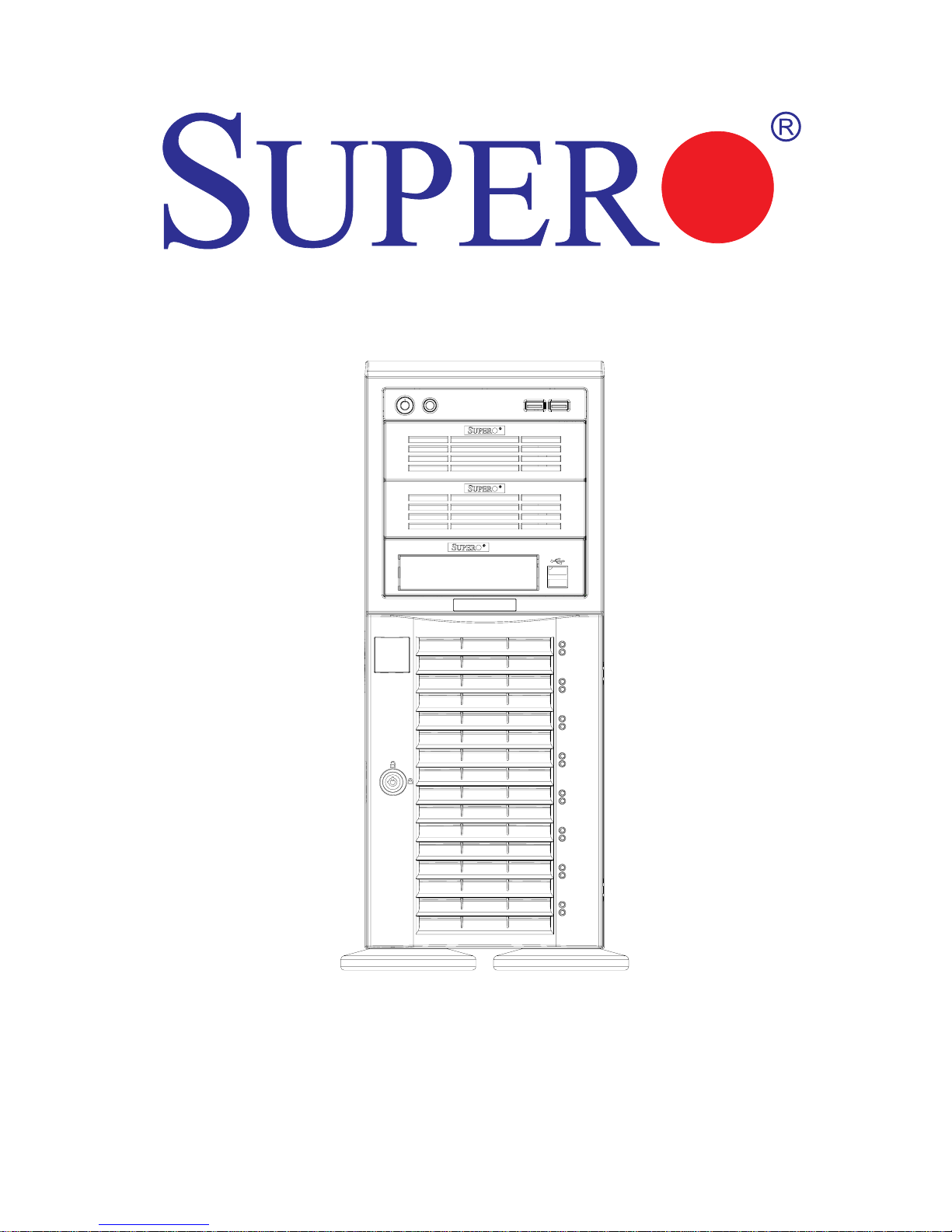
1.1b
SC743 CHASSIS
USER'S GUIDE
Page 2

1-2
SC743 Chassis User’s Guide
The information in this User’s Guide has been carefully reviewed and is believed to be
accurate. The vendor assumes no responsibility for any inaccuracies that may be
contained in this document, makes no commitment to update or to keep current the
information in this manual, or to notify any person or organization of the updates.
Please
Note: For the most up-to-date version of this manual, please see our
web site at www.supermicro.com.
SUPERMICRO COMPUTER reserves the right to make changes to the product described in
this manual at any time and without notice. This product, including software, if any, and
documentation may not, in whole or in part, be copied, photocopied, reproduced, translated
or reduced to any medium or machine without prior written consent.
IN NO EVENT WILL SUPERMICRO COMPUTER BE LIABLE FOR DIRECT, INDIRECT,
SPECIAL, INCIDENTAL, OR CONSEQUENTIAL DAMAGE ARISING FROM THE USE OR
INABILITY TO USE THIS PRODUCT OR DOCUMENTATION, EVEN IF ADVISED OF THE
POSSIBILITY OF SUCH DAMAGE. IN PARTICULAR, THE VENDOR SHALL NOT HAVE
LIABILITY FOR ANY HARDWARE, SOFTWARE, OR DATA STORED OR USED WITH THE
PRODUCT, INCLUDING THE COSTS OF REPAIRING, REPLACING, INTEGRATING,
INSTALLING OR RECOVERING SUCH HARDWARE, SOFTWARE, OR DATA.
Any disputes arising between manufacturer and customer shall be governed by the laws of
Santa Clara County in the State of California, USA. The State of California, County of
Santa Clara shall be the exclusive venue for the resolution of any such disputes.
Supermicro's total liability for all claims will not exceed the price paid for the hardware
product.
Unless you request and receive written permission from SUPER MICRO COMPUTER, you
may not copy any part of this document.
Information in this document is subject to change without notice. Other products and
companies referred to herein are trademarks or registered trademarks of their respective
companies or mark holders.
Copyright © 2006 by SUPER MICRO COMPUTER INC.
All rights reserved.
Printed in the United States of America
Revision : 1.1b
Release Date: Jan. 3, 2006
Page 3

1-3
Chapter 1: Safety Information and Technical Specifications
Table of Contents
Chapter I: Safety Information and Technical Specifications.......... 1-4
1-1. Electrical Safety Guidelines ............................................................. 1-4
1-2. General Safety Guidelines............................................................... 1-5
1-3. ESD Safety Guidelines ....................................................................... 1-6
1-4. Operation Safety Guidelines.......................................................... 1-6
1-5. Product Compliance Information................................................. 1-8
1-6. The SC743 Series: Packing List and Specifications ............. 1-9
1-7. The SC743 Series: Packing List, Specifications & Back Panels
......................................................................................................................... 1-10
Chapter 2: Chassis Description and Installation Procedures........ 2-1
2-1. Chassis Description ........................................................................... 2-1
A. Contents of the Accessory Kit ............................................................... 2-1
B. Chassis Front View and the Front Control Panel ................................ 2-2
C. Chassis Rear View and the Back Panel .............................................. 2-4
2-2. Chassis Installation ........................................................................... 2-6
A. Important Safety Guidelines ..................................................................... 2-6
B. Tools Needed.............................................................................................. 2-6
C. Accessing the SCA Drive Tray and Installing a Hard Drive .............. 2-7
D. Removing the Top Cover of the Chassis ...............................................2-8
E. Accessing the Front Chassis Fans ........................................................ 2-9
F. Accessing the Power Supply ................................................................ 2-12
G. Installing the Motherboard ...................................................................... 2-13
H. Accessing the Interior between the Back Panel and the Mid-plane ......
......................................................................................................................... 2-15
I. Installing the PCI cards ............................................................................. 2-16
J. Installing 5.25" or 3.5" Devices ............................................................. 2-17
K. Installing the Air Shroud ........................................................................ 2-20
L. Installing the Chassis Rails ................................................................... 2-21
Addendum A: Installing the CSE-M34T Mobile Rack ....................... A-1
Addendum B: Installing the CSE-M35S/T1 Mobile Rack ................. B-1
Page 4
1-4
SC743 Chassis User’s Guide
Chapter 1-Safety Information and Technical
Specifications
1-1 Electrical Safety Guidelines
Warning: To avoid electrical shock, check the power
cords as follows:
Checking the Power Cords
zUse the exact type of power cords as required.
zBe sure to use power cord(s) that came with safety certifications.
zThe power cord(s) must be compliant with the AC voltage requirements in your
region.
zThe power cord plug cap must have an electrical current rating that is at least
125% of the electrical current rating of this product.
zThe power cord plug cap that plugs into the AC receptacle on the power
supply must be an IEC 320, sheet C13, type female connector.
zBe sure to disconnect the power supply before accessing the SC743 or its
components.
zPlug the Power cord(s) into a socket that is properly grounded before
turning on the power.
Warning: Follow the guidelines below to avoid possible
damage to the system or injury to yourself:
General Electrical Safety Guidelines
z Be aware of the locations of the power switches on the chassis and in the
room, so you can disconnect the power supply if an accident occurs.
z Take extra precautionary measures when working with high voltage
components. It is not recommended to work alone.
z Before removing or installing main system components, be sure to
disconnect the power first. Turn off the system before you disconnect
the power supply.
Use only one hand when working with powered-on electrical equipment to
avoid possible electrical shock.
!
!
Page 5
1-5
Chapter 1: Safety Information and Technical Specifications
Use rubber mats specifically designed as electrical insulators when working
with computer systems.
The power supply or power cord must include a grounding plug and must
be plugged into grounded outlets.
Motherboard Battery: CAUTION -Make sure not to install the onboard battery
upside down to avoid possible explosion. Make sure that the positive side
is facing up on the motherboard. This battery must be replaced only with
the same or an equivalent type recommended by the manufacturer.
Dispose of used batteries according to the manufacturer's instructions.
CD-ROM Laser: CAUTION - Do not open the enclosures of power supplies
or CD ROM to avoid injury.
1-2 General Safety Guidelines
Warning!! Follow the guidelines below to avoid
possible damage to the system or injury to yourself:
Keep the area around the SC743 clean and free of clutter.
To avoid injuries to your back, be sure to use your leg muscles, keep your
back straight, and bend your knees, when lifting the system.
Avoid wearing loose clothing to preventing it from coming into contact with
electrical circuits or being pulled into a cooling fan.
The handles are for sliding the chassis in and out of the
racks only. Do not carry the chassis by the handles.
After removing the components or chassis covers from the system, place
them on a table for safeguard.
!
Page 6

1-6
SC743 Chassis User’s Guide
1-3 ESD Safety Guidelines
Use a grounded wrist strap designed to prevent static discharge.
Keep all components and printed circuit boards (PCBs) in their antistatic
bags until ready for use.
Touch a grounded metal object before removing the board from the antistatic bag.
Do not let components or PCBs come into contact with your clothing, which may
retain a charge even if you are wearing a wrist strap.
Touch a grounded metal object before removing the board from the antistatic
bag.
Handle a board by its edges only; do not touch its components, peripheral
chips, memory modules or contacts.
When handling chips or modules, avoid touching their pins.
Put the motherboard and peripherals back into their antistatic bags when not in
use.
For grounding purposes, make sure your computer chassis provides excel-
lent conductivity between the power supply, the case, the mounting
fasteners and the motherboard.
Electric Static Discharge (ESD) can damage electronic components. To prevent damage to your system board, it is
important to handle it very carefully. The following measures are
generally sufficient to protect your equipment from ESD.
1-4 Operation Safety Guidelines
Warning: For proper cooling, make sure to install all
chassis covers before turning on the system. If this rule is
not strictly followed, warranty may become void. Do not open
the casing of a power supply. Power supplies can only be
accessed and serviced by a qualified technician of the manufacturer.
!
!
Page 7

1-7
Chapter 1: Safety Information and Technical Specifications
To avoid personal injury and property damage, please carefully
follow all the safety steps listed below:
Before accessing the chassis:
1. Turn off all peripheral devices connected to the SC743.
2. Press the power button to power off the system.
3. Unplug all power cords from the system or the wall outlets.
4. Disconnect all the cables and label the cables for easy identification.
5. Use a grounded wrist strap designed to prevent static discharge when
handling components.
Removing the chassis covers:
After completing the above steps, you can remove the covers and install
components/peripheral devices into the chassis as described in Chapter 2.
1. Unlock and remove the screws and fasteners to remove the cover or
components.
2. Save all the screws and fasteners for later use. (If necessary, label these
screws or fasteners for easy identification.)
3. Follow the instruction given in Chapter 2 to remove the chassis covers.
Reinstalling the chassis covers:
To maintain proper system cooling and airflow, do not operate the system
without installing all chassis covers back to the chassis. To reinstall the chassis
covers, please follow the steps listed below:
1. Make sure that all components and devices are securely fastened
on the chassis and there are no loose parts/screws inside the chassis.
2. Make sure that all cables are properly connected to the connectors and ports.
3. Use the original screws or fasteners to install the covers to the chassis.
4. Be sure to lock to the chassis or the system to prevent unauthorized access.
5. For proper cooling, enclose the chassis with covers before operating the
system.
STOP
Page 8

1-8
SC743 Chassis User’s Guide
Before installing the chassis into a rack:
1. Make sure that the rack is securely anchored onto an unmovable surface or
structure before installing the chassis into the rack.
2. Unplug the power cord(s) of the rack before installing the chassis into the
rack.
3. Make sure that the system is adequately supported. Make sure that all the
components are securely fastened to the chassis to prevent components
falling off from the chassis.
4. Be sure to install an AC Power Disconnect for the entire rack assembly and
this Power Disconnect must be clearly marked.
5. The rack assembly shall be properly grounded to avoid electrical shock.
6. The rack assembly must provide sufficient airflow to the chassis for proper
cooling.
1-5 Product Compliance Information
The SC743 Chassis is compliant with the following safety standards/
requirements:
Product Safety
*Canada/USA--UL60 950-CSA60 950
*European Union--EN 60 950
*International--IEC 60 950
Electromagnetic Compatibility (EMC)-Emissions
*European Union--EN55022: 1994
*International--CISPR 22
*USA--Title 47 CFR, Part 15
Power Line Harmonics/Voltage Flicker
*European Union--EN61000-3-2/EN61000-3-3
*International--IEC61000-3-2
Electromagnetic Compatibility-Immunity
*European Union--EN55024: 1998
*International--CISPR 24
All images and layouts shown in this manual were based upon the latest
chassis Revision available at the time of publishing. The chassis you’ve
received may or may not look exactly the same as the ones shown in this
manual.
1-6 An important note to the user
Page 9
1-9
Chapter 1: Safety Information and Technical Specifications
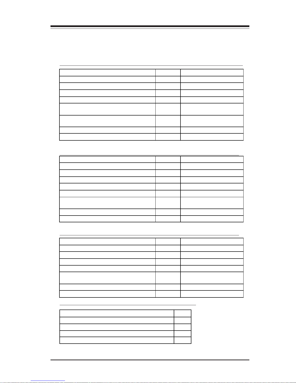
A1. The SC743S1/743i-R760(B) chassis contains the following:
1-6A Packing List and Chassis Specifications for
the SC743S1/743i Series--Revision A
(*Note: Please refer to Page 1-13 for the Power Supply Specifications.)
Component Quantity Part Number
SCA 1” Drive Tray (*SC743S1 only) 8 CSE- PT17 (B)
IDE Drive Carriage (*SC743i only)
2 CSE- PT31 (B)
80mm Hot-Swap Chassis Fan
4 FAN-0072
80mm Rear Chassis Fan (Hot Swap) 2 Fan-0073
760 W Triple Redundant (2+1) Power
Supply
1 PWS-0050
8-port SCSI Single-channel w/SAF-TE Back
plane (*SC743S1 o n l y )
1 CSE-SCA -743S1
Fan Shroud
1 CSE- PT54
SCSI Cable (”9”) (*SC743S1 o n l y )
1 CBL-033-U320
Component Quantity Part Number
SCA 1” Drive Tray (*SC743S1 only) 8 CSE- PT17 (B)
IDE Drive Carriage (*SC743i only)
2 CSE- PT31 (B)
80mm Hot-Swap Chassis Fan
4 FAN-0072
80mm Rear Chassis Fan (Hot Swap) 2 Fan-0073
650W Power Supply
1 PWS-0056
8-port SCSI Single-channel w/SAF-TE Back
plane (*SC743S1 o n l y )
1 CSE-SCA -743S1
Fan Shroud
1 CSE- PT54
SCSI Cable (”9”) (*SC743S1 o n l y )
1 CBL-033-U320
Component Quantity Part Number
SCA 1” Drive Tray (*SC743S1 only) 8 CSE- PT17 (B)
IDE Drive Carriage (*SC743i only)
2 CSE- PT31 (B)
80mm Hot-Swap Chassis Fan
4 FAN-0074
645W Power Supply
1 PWS-0060
8-port SCSI Single-channel w/SAF-TE
Backplane (*SC743S1)
1 CSE-SCA -743S1
Fan Shroud
1 CSE- PT54
SCSI Cable (”9”) (SC743S1)
1 CBL-033-U320
A2. The SC743S1/743i-650(B) chassis contains the following:
A3. The SC743S1/743i-645(B) chassis contains the following:
B. The SC743S1/743i Accessory Box contains:
Component
Qty
AC Power Cords (*SC743S1/743i-R760(B) only) 3
AC Power Cord (*SC743S1/743i-650,645 only) 1
Motherboard Screws and Standoffs 1 set
HDD Screws 1 set
Page 10
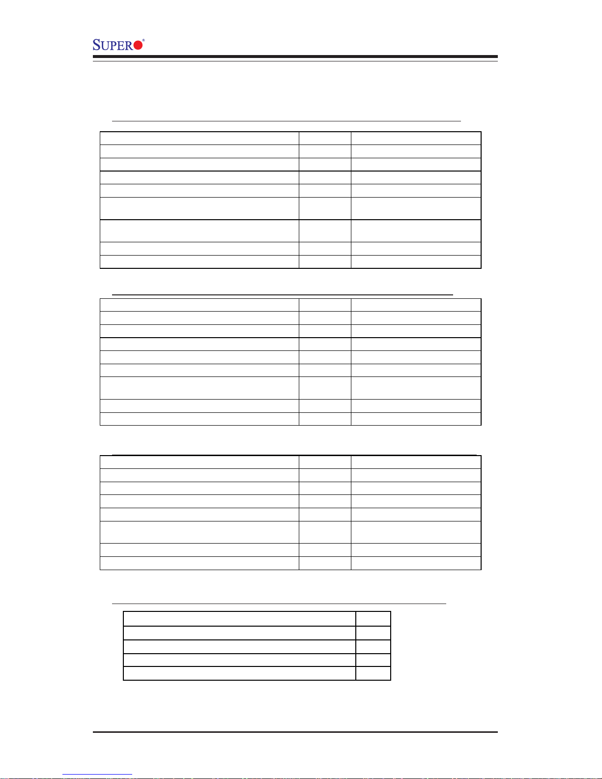
1-10
SC743 Chassis User’s Guide
Component Quantity Part Number
SCA 1” Drive Tray (*SC743S1 only) 8 CSE-PT17 (B)
IDE Drive Carriage (*SC743i only)
2 CSE-PT31 (B)
80mm Hot-Swap Chassis Fan
4 FAN-0072
80mm Rear Chassis Fan (Hot Swap) 2 Fan-0081
760 W Triple Redundant (2+1) Power
Supply
1 PWS-0050
8-port SCSI Single-channel w/SAF-TE Back
plane (*SC743S1 onl y )
1 CSE-SCA-743S1
Fan Shroud (Rev. B)
1 CSE-PT54
SCSI Cable (”9”) (*SC743S1 on l y )
1 CBL-033-U320
Component Quantity Part Number
SCA 1” Drive Tray (*SC743S1 only) 8 CSE-PT17 (B)
IDE Drive Carriage (*SC743i only)
2 CSE-PT31 (B)
80mm Hot-Swap Chassis Fan
4 FAN-0072
80mm Rear Chassis Fan (Hot Swap) 2 Fan-0081
650W Power Supply
1 PWS-0056
8-port SCSI Single-channel w/SAF-TE Back
plane (*SC743S1 onl y )
1 CSE-SCA-743S1
Fan Shroud (Rev. B)
1 CSE-PT54
SCSI Cable (”9”) (*SC743S1 on l y )
1 CBL-033-U320
Component Quantity Part Number
SCA 1” Drive Tray (*SC743S1 only) 8 CSE-PT17 (B)
IDE Drive Carriage (*SC743i only)
2 CSE-PT31 (B)
80mm Hot-Swap Chassis Fan
4 FAN-0074
645W Power Supply
1 PWS-0060
8-port SCSI Single-channel w/SAF-TE
Backplane (*SC743S1)
1 CSE-SCA-743S1
Fan Shroud (Rev. B)
1 CSE-PT54
SCSI Cable (”9”) (SC743S1)
1 CBL-033-U320
A1. The SC743S1/743i/SC743S2-R760(B) chassis contains:
1-6B Packing List and Chassis Specifications for
the SC743S1/743i/SC743S2 Series--Revision B
A2. The SC743S1/743i/SC743S2-650(B) chassis contains:
A3. The SC743S1/743i-645(B) chassis contains the following:
Component
Qty
AC Power Cords (*SC743S1/743i-R760(B) only) 3
AC Power Cord (*SC743S1/743i-650,645 only) 1
Motherboard Screws and Standoffs 1 set
HDD Screws 1 set
B. The SC743S1/743i/SC743S2 Accessory Box contains:
(*Note: Please refer to Page 1-13 for the Power Supply Specifications.)
Page 11
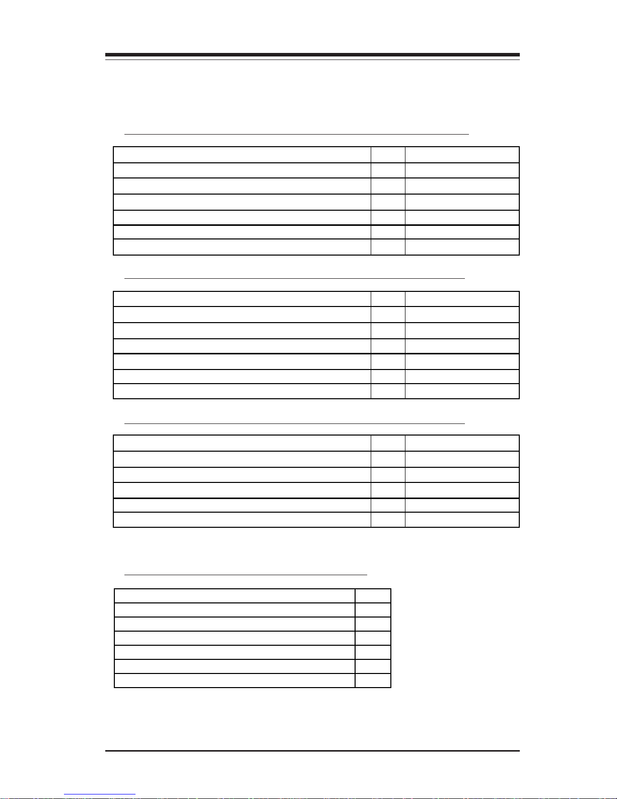
1-11
Chapter 1: Safety Information and Technical Specifications
1-7A Packing List, Chassis Specifications and Back
Panels for the SC743T Series--Revision A
A1. The SC743T-760 (B) chassis contains the following:
B. The SC743 Accessory Box contains:
(*Note: Please refer to Page 1-13 for the Power Supply Specifications.)
Component Qty Part Number
SCA 1” Drive Trays 8 CSEPT17(B)
80mm Hot-Swap Chassis Fan
4 FAN-0072
80mm Hot-Swap Rear Chassis Fan
2 FAN-0073
760W Triple Redundant (2+1) Power
1 PWS-0050
8-port SATA Backplane
1 CSE-SATA -743
Fan Shroud
1 CSE- PT54
Component Qty Part Number
SCA 1” Drive Trays 8 CSEPT17(B)
80mm Hot-Swap Chassis Fan
4 FAN-0072
80mm Hot-Swap Rear Chassis Fan
2 FAN-0073
650W Power Supply
1 PWS-0056
8-port SATA Backplane
1 CSE-SATA -743
Fan Shroud
1 CSE- PT54
Component Qty Part Number
SCA 1” Drive Trays 8 CSEPT17(B)
80mm Hot-Swap Chassis Fan
4 FAN-0074
645W Power Supply
1 PWS-0060
8-port SATA Backplane
1 CSE-SATA -743
Fan Shroud
1 CSE- PT54
A2. The SC743T-650(B) chassis contains the following:
A3. The SC743T-645(B) chassis contains the following:
Component
Qty
AC Power Cords (*SC743T-R760 (B) only) 3
AC Power Cord (*SC743T-650,645 only) 1
Motherboard Screws and Standoffs 1 set
HDD Screws 1 set
SATA Cable (CBL-0044) 4
SATA LED Cable (CBL-0077) 1
Page 12
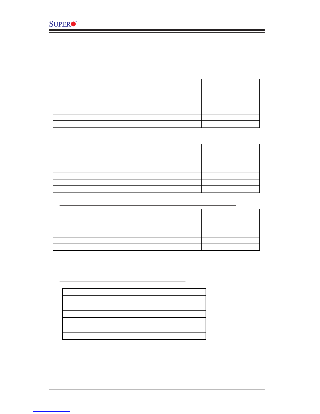
1-12
SC743 Chassis User’s Guide
Component Qty Part Number
SCA 1” Drive Trays 8 CSEPT17(B)
80mm Hot-Swap Chassis Fan
4 FAN-0072
80mm Hot-Swap Rear Chassis Fan
2 FAN-0081
760W Triple Redundant (2+1) Power
1 PWS-0050
8-port SATA Backplane
1 CSE-SATA-743
Fan Shroud (Rev. B)
1 CSE-PT54
Component Qty Part Number
SCA 1” Drive Trays 8 CSEPT17(B)
80mm Hot-Swap Chassis Fan
4 FAN-0072
80mm Hot-Swap Rear Chassis Fan
2 FAN-0081
650W Power Supply
1 PWS-0056
8-port SATA Backplane
1 CSE-SATA-743
Fan Shroud (Rev. B)
1 CSE-PT54
Component Qty Part Number
SCA 1” Drive Trays 8 CSEPT17(B)
80mm Hot-Swap Chassis Fan
4 FAN-0074
645W Power Supply
1 PWS-0060
8-port SATA Backplane
1 CSE-SATA-743
Fan Shroud (Rev. B)
1 CSE-PT54
1-7B Packing List, Chassis Specifications and Back
Panels for the SC743T Series--Revision B
A2. The SC743T-650(B) chassis contains the following:
A3. The SC743T-645(B) chassis contains the following:
B. The SC743 Accessory Box contains:
(*Note: Please refer to the next page for the Power Supply Specifications.)
Component
Qty
AC Power Cords (*SC743T-R760 (B) only) 3
AC Power Cord (*SC743T-650,645 only) 1
Motherboard Screws and Standoffs 1 set
HDD Screws 1 set
SATA Cable (CBL-0044) 4
SATA LED Cable (CBL-0077) 1
A1. The SC743T-760 (B) chassis contains the following:
Page 13

1-13
Chapter 1: Safety Information and Technical Specifications
C. SC743 Power Supply Specifications
Power supply spec SC743 series
Mfr. model # SP762-TS(3xSP382-TS Models)
Mfr. part # PWS-0050
Rated AC input voltage 100-240V AC
Rated input frequency 50-60 Hz
Rated input current 14A (115V)
8A (230V)
Rated output power 760W
Maximum rated BTU 4350 BUTs/Hr
Nominal DC output
+3.3V 36A
+5V 36A
+12V 50A combined
-12V 1A
+5V Standby 3.5A
(*Note: When connecting the 760W Power Supply to the Drive Backplane,
be sure to connect the power supply to the connectors labelled "PD", "PE"
and "PH" (with yellow/green stripes), and then, to the connector labelled
"PJ", colored in yellow/blue stripes.)
Page 14
1-14
SC743 Chassis User’s Guide
GND
GND
GND
GND
+12V
+12V
+5V
+5V
IN
IN
1
1
+
+
+
+
+
+
+
+
+
+
+
+
+
+
+
+
1
1
IIC
C
2
2
+5V
+5V
GND
GND
GND
GND
+12V
+12V
BUZZER
BUZZER
IPMB
IPMB
DOORLOCK
DOORLOCK
RESET
RESET
1
1
1
1
+
+
+
+
+
+
+
+
+
+
+
+
+
+
+
+
+
+
+
+
ENABLE
ENABLE
+
+
1
1
D3:
D3:
1
1
1
1
REV 1.00
REV 1.00
SCA743S1
SCA743S1
S
S
UPER
UPER
R
R
OFF: DISABLE
OFF: DISABLE
ON: ENABLE
ON: ENABLE
JP19: BUZZER ENABLE
JP19: BUZZER ENABLE
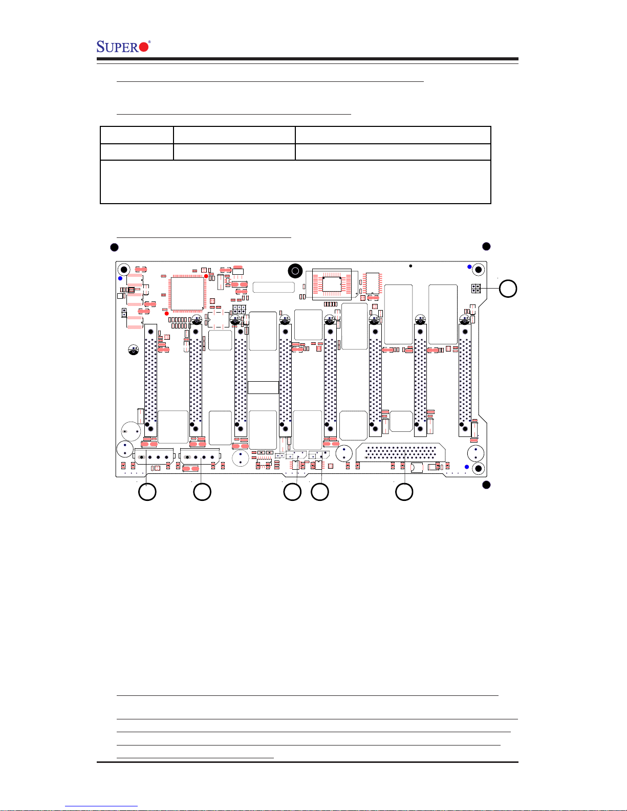
D. SCSI 743 Back Panel (*SC743S1/SC743S2 Only)
D-1 Jumper Settings and Pin Definitions
D-2 Jumper Setting Locations
A
BCDEF
Note1: By default, we connect four chassis fans to the drive backpanel.
Note2: When connecting the 760W Power Supply to the Drive Backplane, be
sure to connect the power supply to the connectors labelled "PD", "PE" and
"PH" (with yellow/green stripes), and then, to the connector labelled "PJ",
colored in yellow/blue stripes.
Jumper Default Setting Note
JP19 Open Buzzer Reset (*Note Below)
(*Note: Press the button on the front panel once to disable the
buzzer. If the buzzer has been disabled, please be sure to press the
button once again to re-enable the buzzer.)
A. Jumper 19
B. SCSI Connector
C. IPMB
D. I2C
E/F 12V PWR Connectors
Page 15

1-15
Chapter 1: Safety Information and Technical Specifications
(*Note: This driver is not necessary for other Operating Systems. If
you have two SCA backplanes, you will need to install the driver
twice.)
The driver is located on the Super Micro motherboard driver CD or is
available for download from our FTP site: ftp://ftp.supermicro.com/driver/
Qlogic/
Follow the procedure below to install this driver to your system.
Installing the driver:
1) Right click on “My Computer” and choose “Property”.
2) Select “Hardware” tab and click on “Device Manager”.
3) Open “Other Devices” or wherever “GEM318” is on.
4) Right click on this device and choose “Property”.
5) Click on “Driver” tab and choose “Update Driver”.
6) Click “Next” 2 times, uncheck both “Floppy disk drives” and “CD-ROM
drives”. Then, select the item- “Specify a location,” and choose
“Next”.
7) Click on “Browse” and choose D drive or wherever Supermicro Setup
CD is in.
8) Choose “Qlogic” folder and click on “Open”.
9) System will automatically detect GEM318 and install the drive from this
point on.
or,
1) Right click the "My Computer" icon on your desktop and choose
Properties.
2) Click on the Hardware tab and click on "Device Manager" to bring up
the list of system devices.
3) You may see one or two yellow question marks (?) that read QLogic
GEM354 or GEM318 SCSI Processor Device. Right click on these, and
choose to uninstall. If two such question marks are present, uninstall
both.
4) Click on Action tab and choose "Scan for Hardware Changes". The
Hardware Wizard program should start up. Click "Next".
5) At the first prompt, choose “Display a list of known device drivers for
the device so that I can choose a specific driver” and click "Next".
6) Choose “Other Devices” and click Next.
7) Choose “Have Disk”, and specify your floppy drive location in the
options box. Then, click "Next".
8) Highlight “Enclosure Services Device” and click "Next".
9) Ignore the warning prompt by clicking "Yes".
D-3 SCSI (Super) GEM Driver Installation (*for Windows OS)
Page 16
1-16
SC743 Chassis User’s Guide
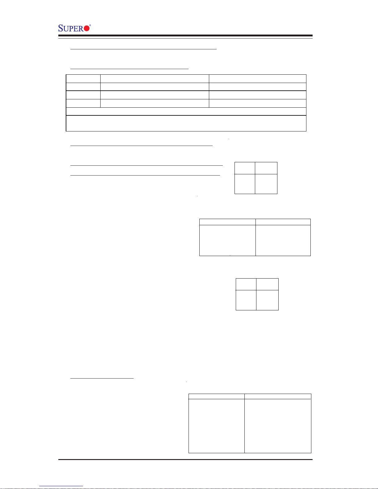
E. SATA743 Back Panel (*SC 743T Only)
E-1 Jumpers and Default Settings
Jumper Description Default
JP18 Buzzer Reset Open
*JP25 Overheat Temperature 50oC 1-2 (*Note 1)
*JP26 Common Act In and Act #0~#7 In Open (*Note 2)
(*Note1: Test if the buzzer is beeping to see if the OH temperature is >=50oC
(*Note2: Test to see if all 8 Activity. LEDs, 8 HDDs, and CBL-0077 are working
properly.)
E-2 Connectors/Jumpers Pin Definitions
(*Note: Please refer to Diagram 1 on the next
page for Jumpers/Connectors locations.)
Pins #
1
2 & 3
4
Definition
+12V
Ground
+5V
Table 1
4-pin PWR Connecto
r
(JP10/JP13)
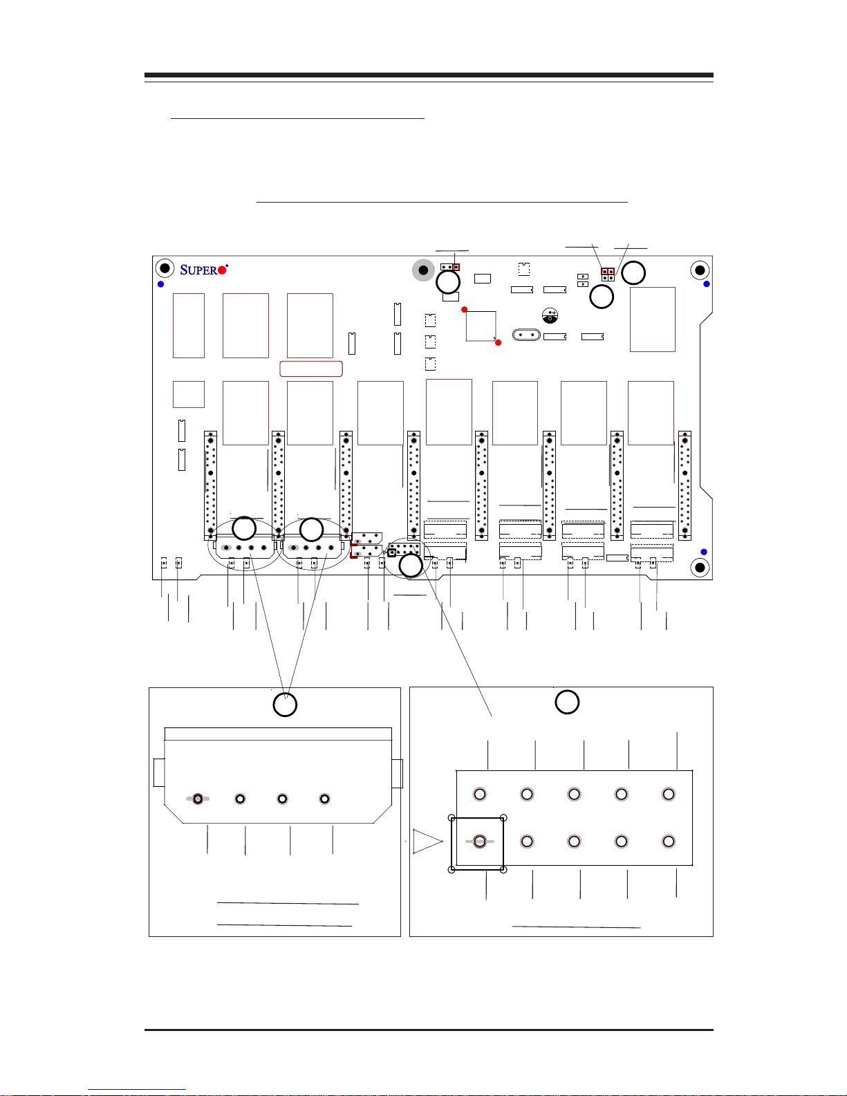
A1/A2. JP10/JP13: 4-Pin Power
Connectors
(*Refer to Table 1 on the right for pin
definitions.)
B. JP26: HDD Activity
(Refer to Table 2 on the right for pin
definitions.)
C. JP25: Overheat Temperatures
(Refer to Table 3 on the right for pin
definitions.)
D. JP35: GEM424 Reset
E. JP18: Buzzer Reset
Table 2
HDD Activity Pin Definitions
(JP26)
Pin Number Definition
1 ACT0
2 ACT1
3 ACT2
4 ACT3
5 COM_ACT
Pin Number Definition
6 ACT4
7 ACT5
8 ACT6
9 ACT7
10 Ground
Pins #
Open
1 & 2
2 & 3
Definition
45
0
C
50
0
C
55
0
C
Table 3
OH Temperature
(JP25)
LED# Function
D5 FAIL0
D12 ACT0
D6 FAIL1
D13 ACT1
D7 FAIL2
D14 ACT2
D8 FAIL3
D15 ACT3
LED# Function
D19 FAIL4
D18 ACT4
D20 FAIL5
D21 ACT5
D23 FAIL6
D22 ACT6
D26 FAIL7
D25 ACT7
LED Indicators
E-3 LED Indicators
D5, D6, D7, D8, D19, D20, D23,
D26: SATA Slots (#0-#7 Fail)
D12, D13, D14, D15, D18, D21,
D22, D27: SATA Slots (#0-#7
Activity)
Page 17
1-17
Chapter 1: Safety Information and Technical Specifications
+
+
1
+12V+12V GND GND GND GND +5V+5V
1
MM1
H6
H5
MT3
MT2
MT1
H2
H12
M7
SATA743
REV. 1.01
J1
J2
J3
J4
J9
J11
J13
J15
+12V GND GND +5V
E-4 Jumpers/Headers Locations
A1
A2
C
D
E
D25
D26
D22
D23
D21
D20
D18
D19
B
A
Pin1
Pin2
Pin3
Pin4
Pin1
Pin2
Pin3
Pin4
Pin5
A1/A2:JP10/JP13:
PWR Connectors
B:JP26: HDD ACT
Pin6
Pin7
Pin8
Pin9
Pin10
D15
D8
D14
D7
D13
D6
D12
D5
B
SATA0
SATA1
SATA2
SATA3
SATA4
SATA5
SATA6
SATA7
SATA0
SATA1
SATA2
SATA3
SATA4
SATA5
SATA8
SATA7
JP18
JP25
JP35
JP10
JP13
JP26
Diagram1: Jumpers and Connectors Locations
Page 18

1-18
SC743 Chassis User’s Guide
Notes
Page 19
2-1
Chapter 2: Chassis Description and Installation Instructions
2-1 Chassis Description
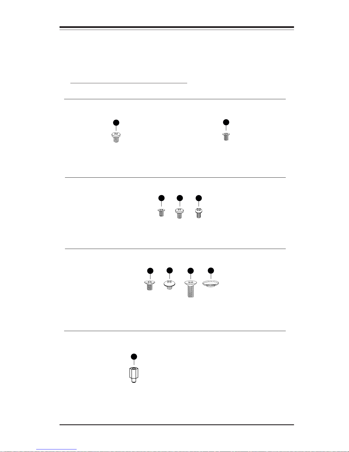
A. Contents of the Accessory Kit:
The following items are included in the Accessory Kit:
Chapter 2: Chassis Description and Installation
Procedures
G
H
F
F. Flat head M4 x 4 mm [0.157]
RAIL
I
G. Round head M4 x 4 mm [0.157]
H. Flat head M5 x 12 mm [0.472]
I. Washer for M5
B
B. Flat head 6-32 x 5 mm [0.197]
DRIVE
D
E
E. Round head M3 x 5 mm [0.197]
D. Pan head 6-32 x 5 mm [0.197]
A
A. Pan head w/ lock
6-32 x 4.5 mm [0.177]
M/B
B
B. Flat head 6-32 x 5 mm [0.197]
HDD
J
J. M/B standoff, 6-32 to 6-32
M/B STANDOFF
Page 20
2-2
SC743 Chassis User’s Guide
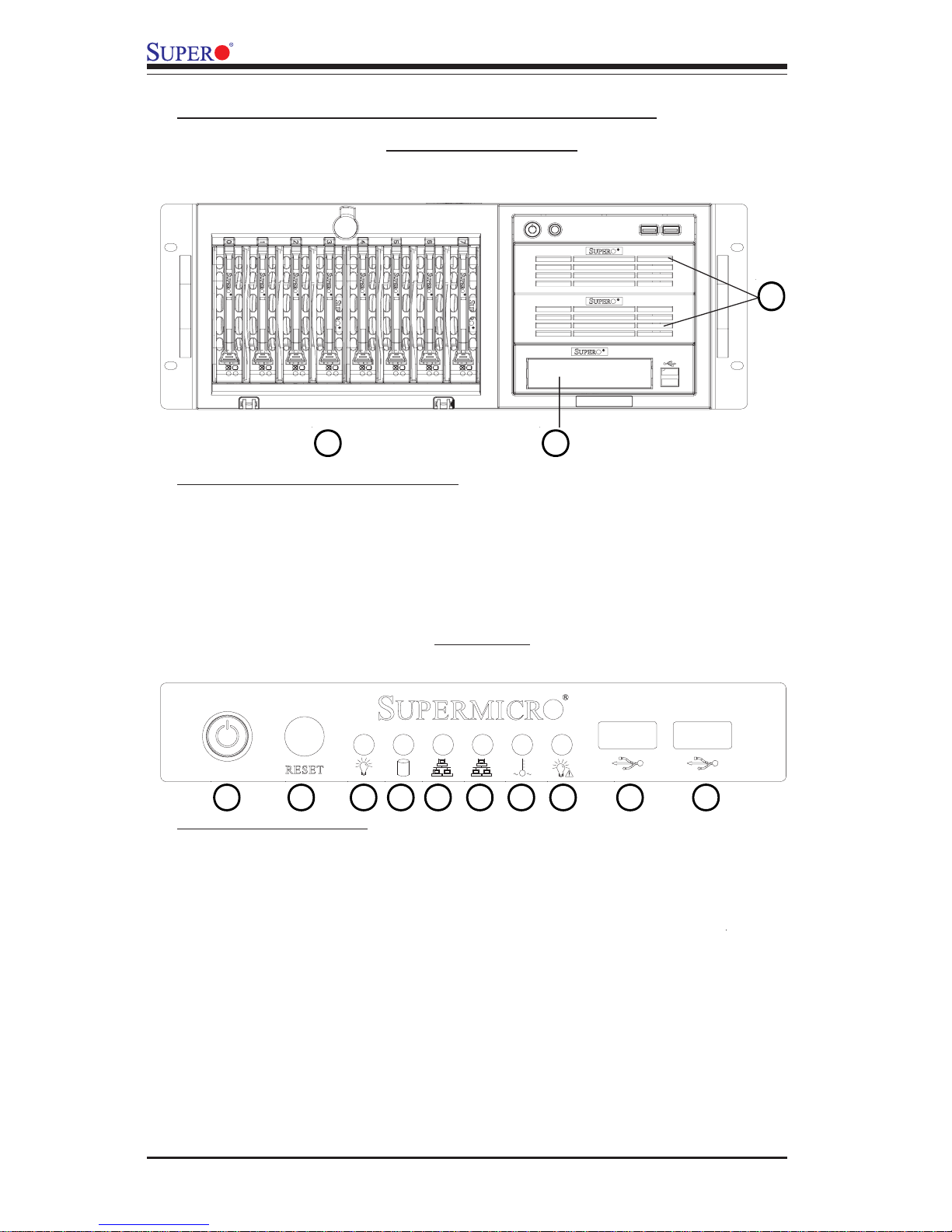
B. Chassis Front View and the Front Control Panel
Front LED
LED Button Definitions
A. Power Button
Chassis Front Panel
Front Panel I/O Device Definitions
K
B. System Reset
C. Power Indicator
D. HDD Activity Indicator
E/F. LAN Indicators
H. Power Failure Indicator
K. Hot-Swappable Drive Trays (8)
I./J USB Ports
L. Floppy Drive Bay
M. 5.25 Drive Trays (2)
A B C D E F G H
I
J
L
M
Page 21
2-3
Chapter 2: Chassis Description and Installation Instructions
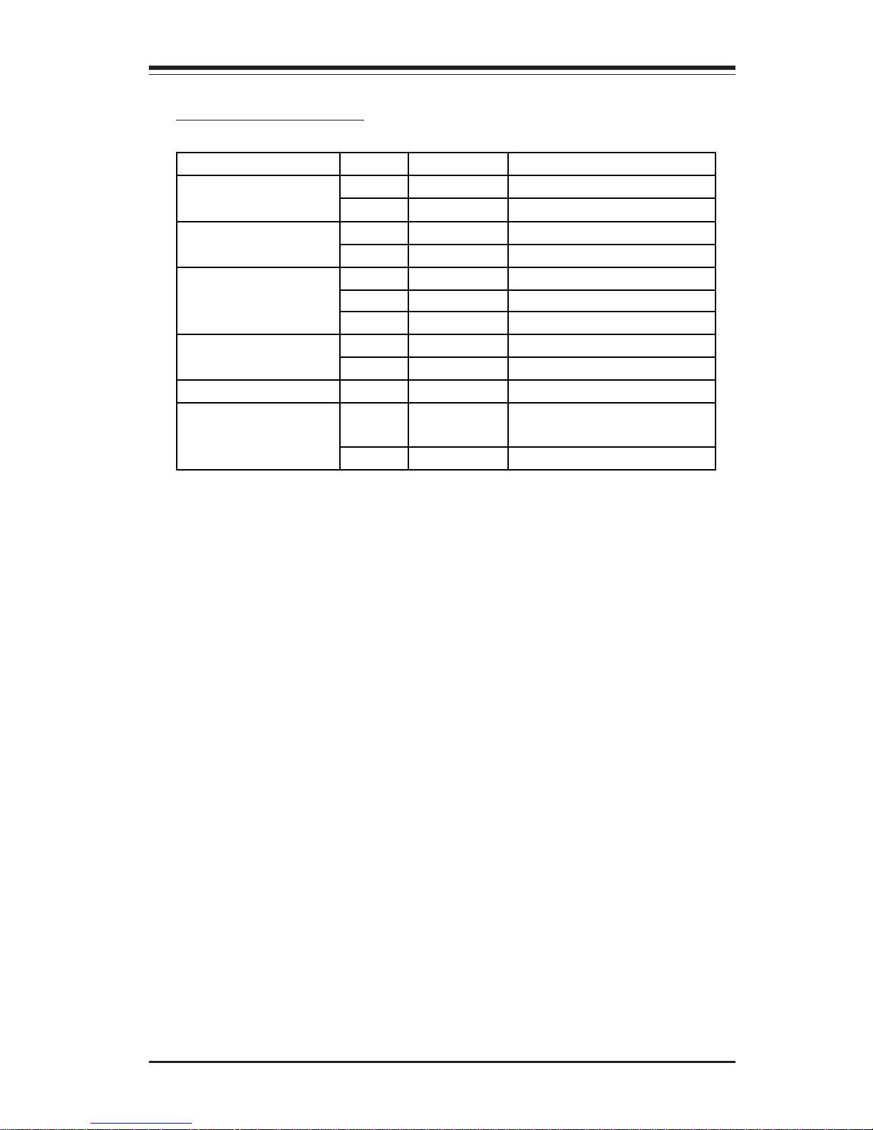
LED Button Descriptions
LED Button Color Condition Description
Green On System On Power
Off System Off
Green Blink HDD Activity HDD Activity
Off No Activity
Green On Linked
Blink LAN Activity
LAN Indicators
Off Disconnected
Red On System Overheat Overheat/Fan Fail
Blink Fan Fail
Off System Normal
Red On 1 or more PWR modules
failure
System Alert/
Power Failure
Off System Normal
Page 22
2-4
SC743 Chassis User’s Guide
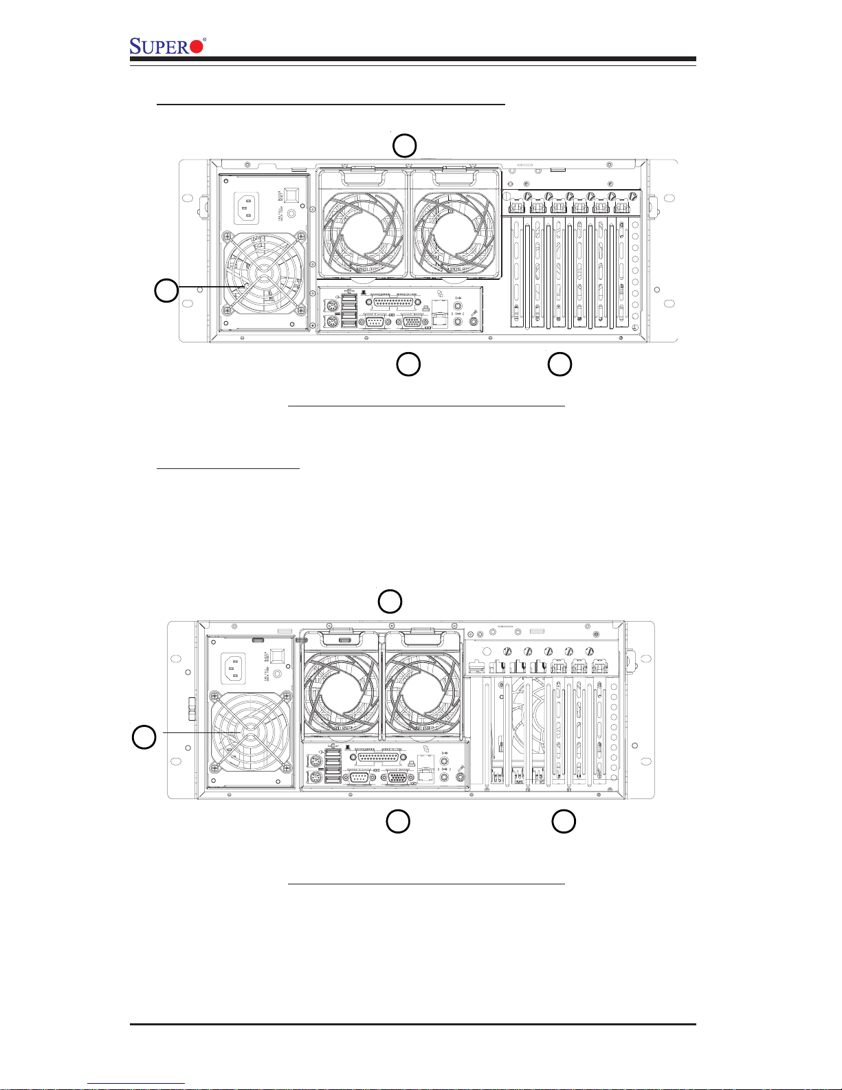
C. Chassis Rear View and the Back Panel
SC743 Chassis-Rev. A Rear View
Back Panel Devices
A. Power Supply Module
B. Back Panel I/O Ports
C. Rear System Fans
A
B
C
D
D. Full-size PCI Expansion Slots
SC743 Chassis-Rev. B Rear View
A
B
C
D
Page 23
2-5
Chapter 2: Chassis Description and Installation Instructions
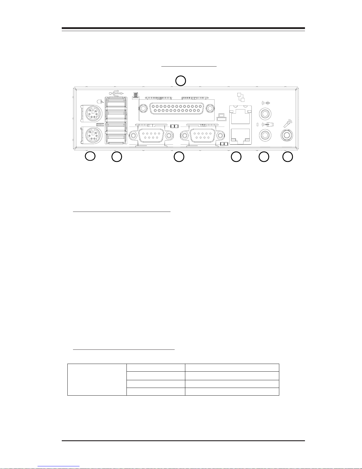
*I/O Back Panel
Back Panel I/O Port Definitions
E. Keyboard & Mouse
F. USB Ports
G. COM/Video Ports
H. LAN1 & LAN2
K. Parallel Port
Power Module LED Descriptions
(*Note: The actual I/O Configuration of your system might be different
from the one shown above.)
E
F G H
I
Color Condition Description
Green
Power Supply DC On
Amber
Power Supply Standby
Power Module
LED
Off
No AC Power to the system
J
K
I. Audio (Line-In: top, Line-out: bottom)
J. Microphone
Page 24

2-6
SC743 Chassis User’s Guide
B. Tools needed
2-2 Chassis Installation
A. Important Safety Guidelines
This product shall only be accessed, assembled and serviced
by technically qualified personnel or technicians.
To avoid personal injury and property damage, please read all the information
provided in Chapter 1, and carefully follow all the Safety Guidelines listed before
accessing or servicing the SC743 or its components. For your convenience, some
Safety Steps are also listed below:
Safety Steps
Before accessing the chassis:
1. Turn off all peripheral devices and turn off the power supply connected to the
SC743.
2. Unplug all power cords from the system or the wall outlets.
3. Disconnect all the cables and label the cables for easy identification.
4. Use a grounded wrist strap designed to prevent static discharge when handling
components.
Removing the chassis covers:
After completing the above steps, you can remove the chassis covers and install
components and devices into the chassis as described in this chapter.
1. Unlock and remove the screws and fasteners to remove the cover or components.
2. Save all the screws and fasteners for later use. (If necessary, label these screws
or fasteners for easy identification.)
3. Follow the instructions given in this chapter to remove the chassis covers.
1. Phillips Screw Driver
2. Antistatic Strap (recommended)
STOP
Page 25
2-7
Chapter 2: Chassis Description and Installation Instructions
2a
2b
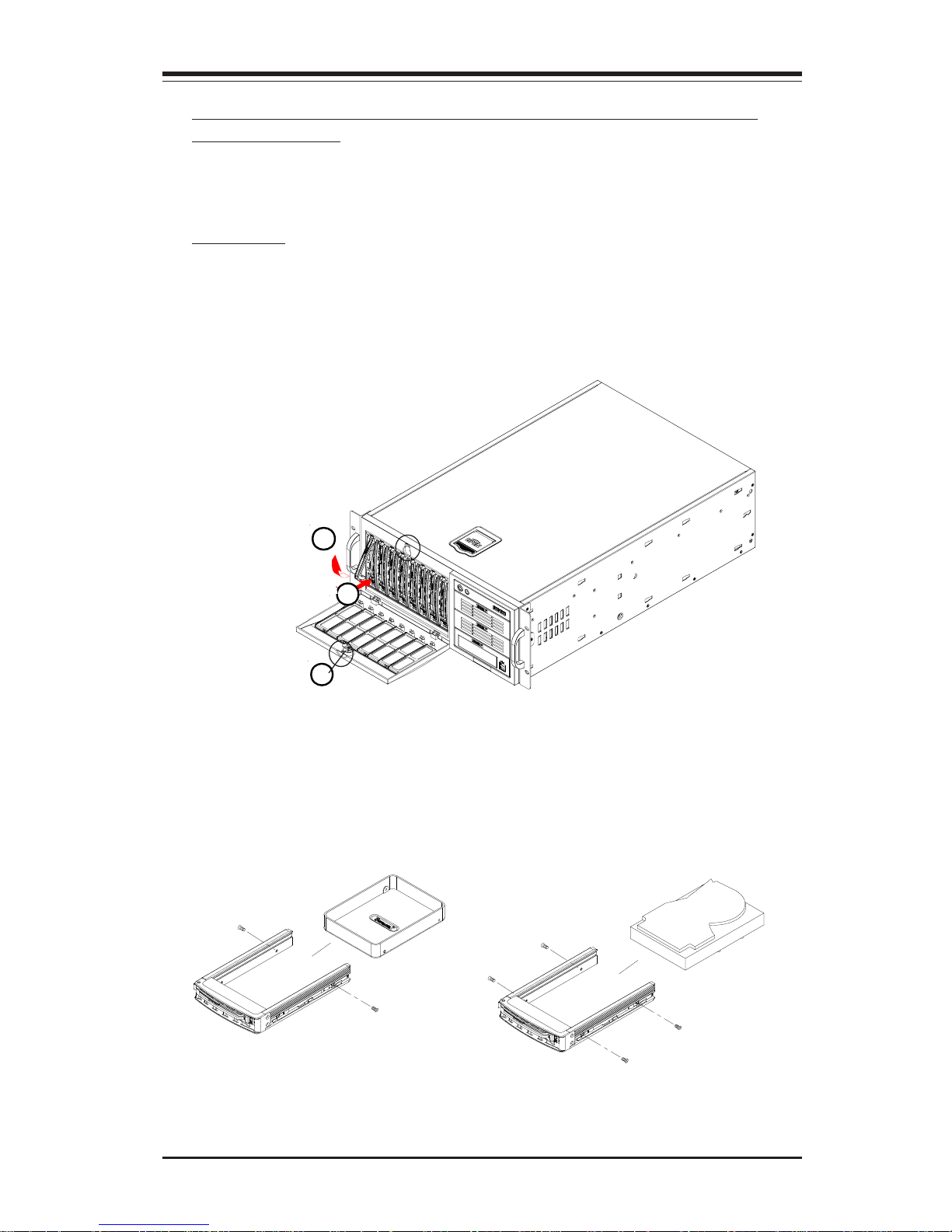
C. Accessing the Hot-Swappable Drive Tray and Installing a
Hard Drive Disk
To install the Hot-Swappable drive into the chassis, you need to first remove the
Hot-Swappable drive tray from the chassis.
Procedures
1. Unlock and open the drive tray door as shown below:
2. Press the release tab located on the drive tray door to release the drive tray
from its locking position.
3. Pull the drive tray door downward and pull the Hot-Swappable drive tray out
from the chassis..
4. Mount a hard drive in the drive tray and make sure that all the screws
are securely fastened as shown below.
1
(*Note: The orientation of the
picture shown below is for
Rack Mount only.)
2
or
3
Page 26
2-8
SC743 Chassis User’s Guide
1b
1a
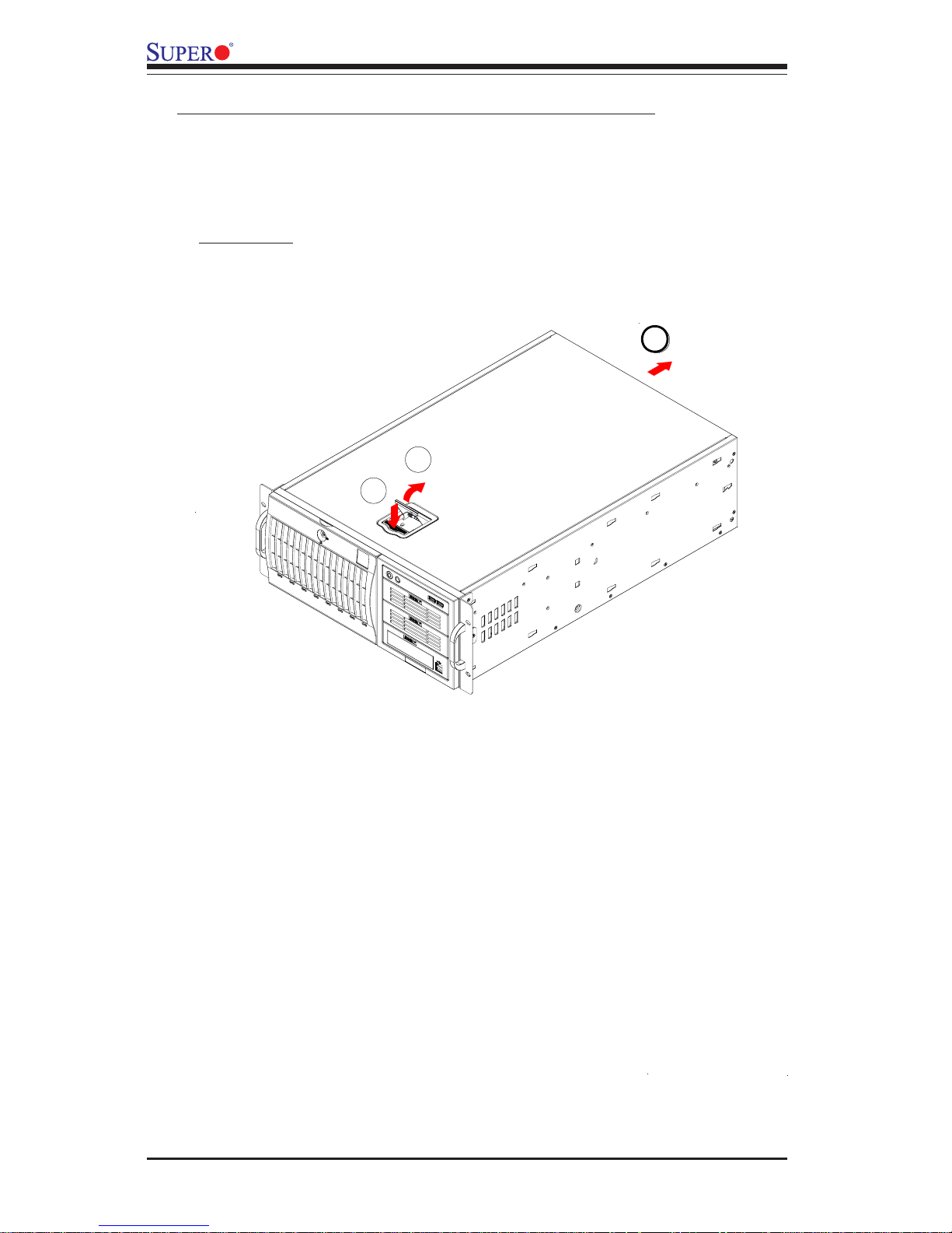
D. Removing the Side Cover of the SC743 Chassis
Before installing any components, replacing chassis fans or accessing the
motherboard, you will first need to remove the side cover.
Procedures
1. Press the release tab to unlock the side cover.
2. Once the release tab pops open, push the cover toward the rear side and slide
it out from the chassis as shown above:
2
Page 27
2-9
Chapter 2: Chassis Description and Installation Instructions
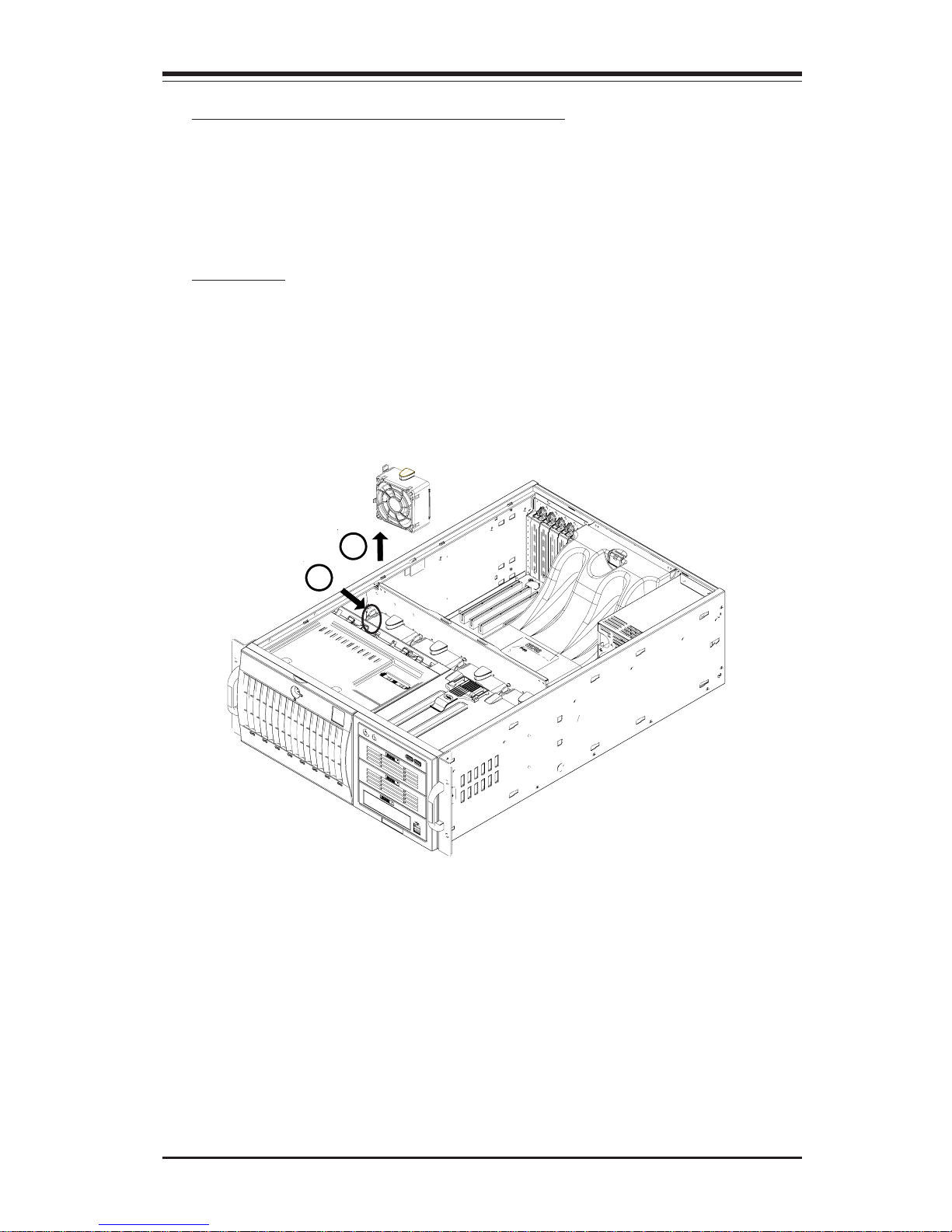
E-1. Accessing the Middle chassis fans
Procedures
1. Press the release tab located on the left side of the middle chassis fan (when
facing the front side of the fan) to the right side to unlock the chassis fan.
2. While pressing the release tab, pull the fan module from the chassis.
(*Note: When installing the fan module into the chassis, be sure to push the fan
module into the fan module slot until you hear the click. *The click sound indicates that the fan module is securely locked in the chassis.)
Before installing the motherboard in the chassis or accessing the motherboard,
you will need to remove the front/rear chassis fans, the air shroud from the
chassis and install the standoffs on the chassis.
2
1
Page 28
2-10
SC743 Chassis User’s Guide
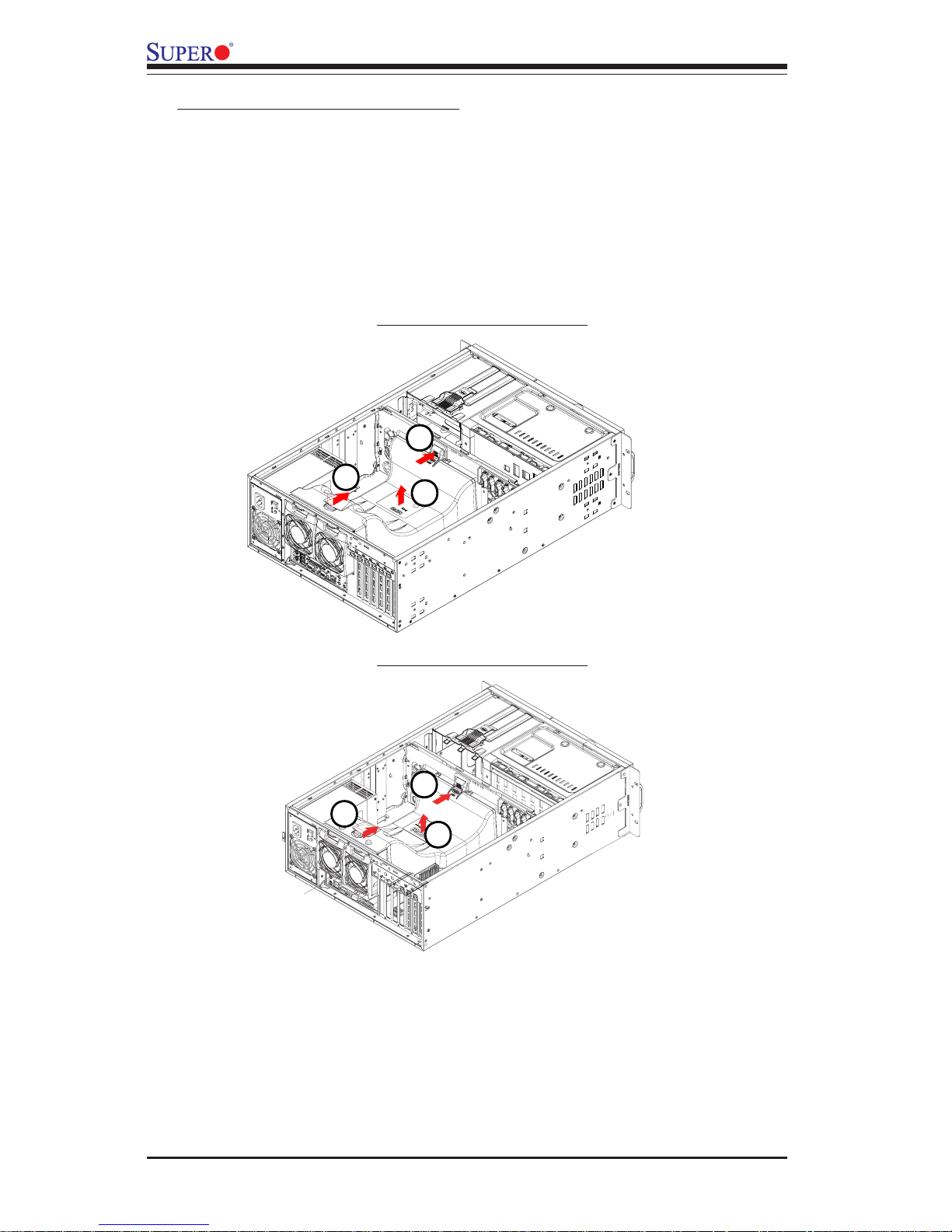
E-2. Removing the Air Shroud
Before installing the motherboard into the chassis, you will need to remove the
air shroud first.
Procedures
1. Press the release tab located on the back side of the middle chassis bracket
as shown below until you hear the click.
2. Press the release tab on the back side of the rear chassis fan to loosen it as
shown above.
3. Once the release tab is loosened, pull the air shroud from the chassis.
(*Note: When installing the air shroud into the chassis, be sure to align the air
shroud against the guide rails and gently push the air shroud into the chassis
until you hear the click. The click sound indicates that the air shroud is securely
locked in the chassis.)
1
2
3
SC743 Chassis-Rev. A
SC743 Chassis-Rev. B
1
2
3
Page 29
2-11
Chapter 2: Chassis Description and Installation Instructions
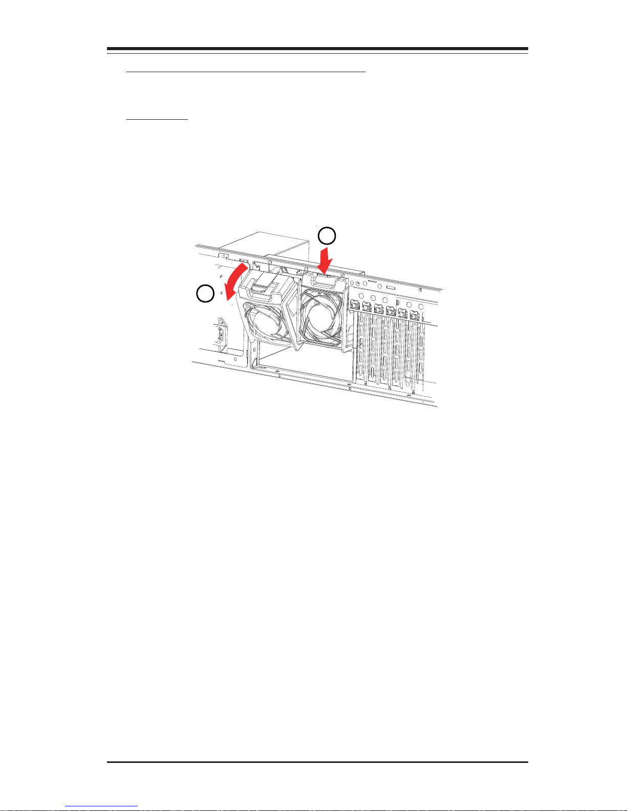
E-3. Accessing the Rear Chassis Fans
Procedures
1. Locate the release tab on the top of the rear chassis fan as shown below.
Push the release tab down to unlock the rear chassis fan.
2. Once the rear chassis fan is unlocked, you can remove the fan from the
chassis as shown above.
(*Note: When installing the fan module into the chassis, be sure to push the fan
module into the fan module slot until you hear the click. *The click sound indicates that the fan module is securely locked in the chassis.)
1
2
Page 30
2-12
SC743 Chassis User’s Guide
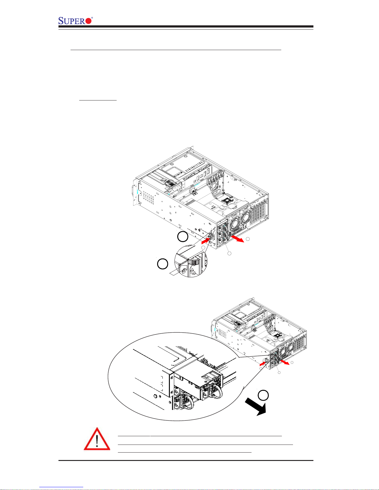
F. Accessing the 760W Triple Redundant Power Supply
Procedures
1. Locate the release tab on the left side of the power supply.
2. Push the release tab to the right to release the power supply from its locking
position as shown below:
3. Once the power supply module is released from its locking position, remove
it from the chassis.
Warning: Do not open the casing of a power supply.
Power supplies can only be accessed and serviced by a
qualified technician from the manufacturer.
(*Caution: Unplug the Power Cord before removing the Power
Supply!!)
1
2
3
Page 31
2-13
Chapter 2: Chassis Description and Installation Instructions
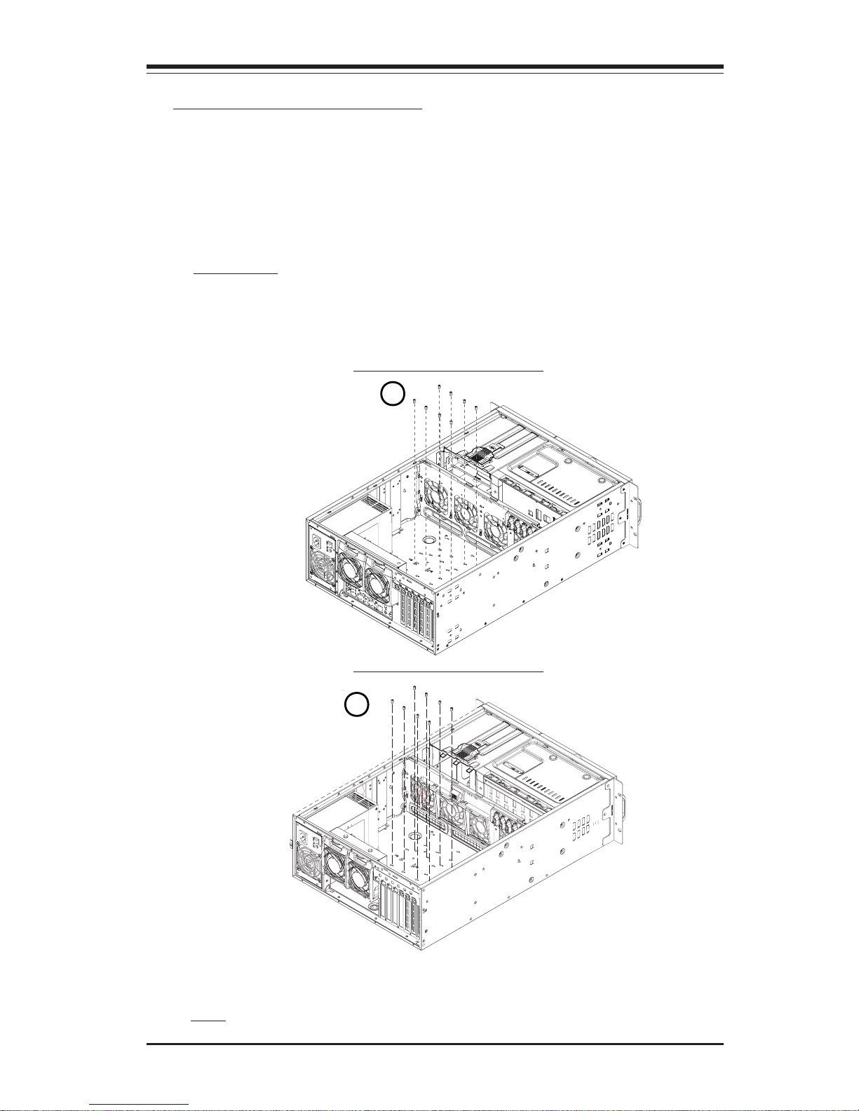
G. Installing the Motherboard
Be sure to disconnect the power supply before accessing or installing the motherboard in the chassis. To install the motherboard, first, you will need to identify
the locations of the processor(s), mounting holes, retention brackets, and then,
install the correct type of standoffs, and heatsink retention brackets under the CPU
or on the motherboard before installing the motherboard into the chassis. (Refer
to Chapter 1 for Safety Guidelines.)
Procedures
(**Note: the motherboard shown above is for reference only!! The motherboard is not included in the SC743 shipping package.)
1
1. Lay the chassis on a flat surface. Locate the mounting holes on the chassis
and install standoffs through the holes on the chassis.
2. Follow the standard procedures to install the I/O shield in the chassis. (*Note:
Install heatsink retention brackets if needed. Refer to your shipping package
for retention brackets and installation guides if any.)
SC743 Chassis-Rev. A
SC743 Chassis-Rev. B
1
Page 32
2-14
SC743 Chassis User’s Guide
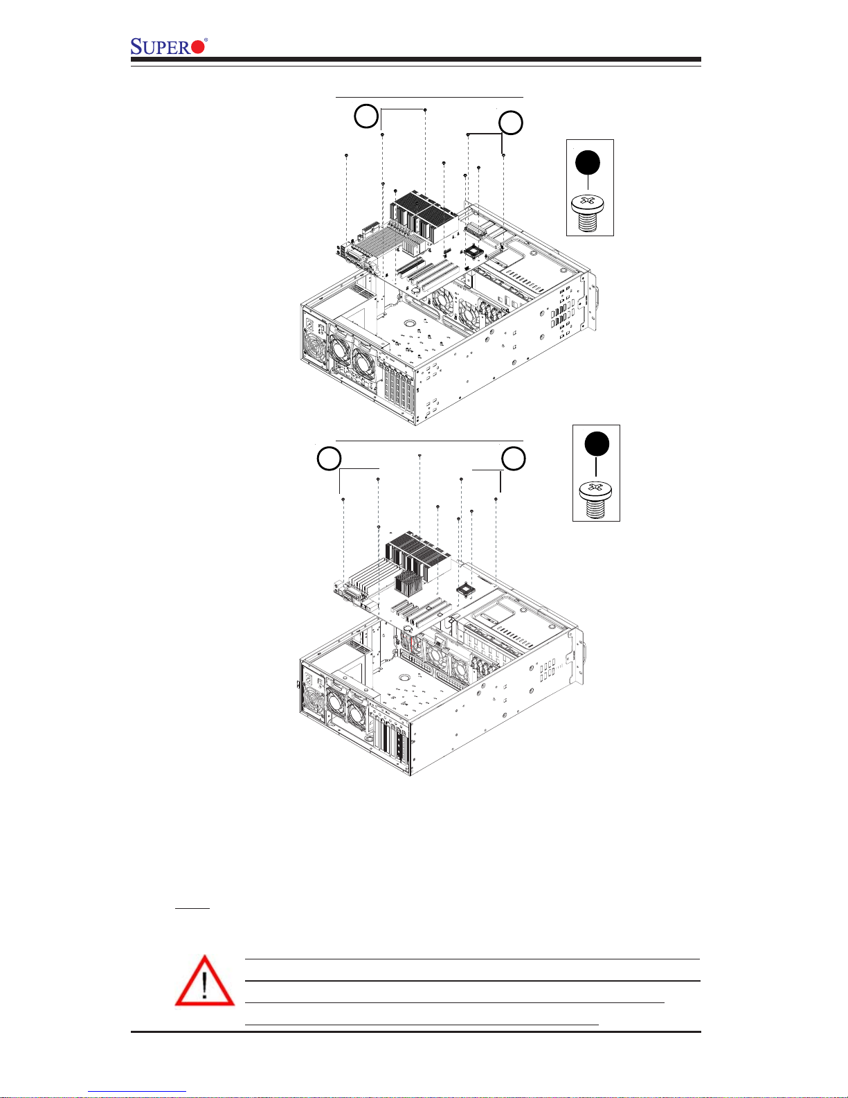
3. Secure the motherboard to the chassis with Type A(6-32) screws as shown
above. (*Please refer to Page 2-1 Motherboard kit for the Type A screw.)
4. Secure the CPU heatsink mechanism to the motherboard.
Warning: For proper cooling, please make sure that the air shroud and
all the chassis covers are installed before you operate the system. Out
-of -warranty damage can occur if this rule is not strictly followed.
Please refer to the next page for Air Shroud Installation.
A
(**Note: the CPUs and Heatsinks shown above are for reference only!! The
motherboard is not included in the SC743 shipping package.)
3
4
SC743 Chassis-Rev. A
SC743 Chassis-Rev. B
A
4 3
Page 33
2-15
Chapter 2: Chassis Description and Installation Instructions
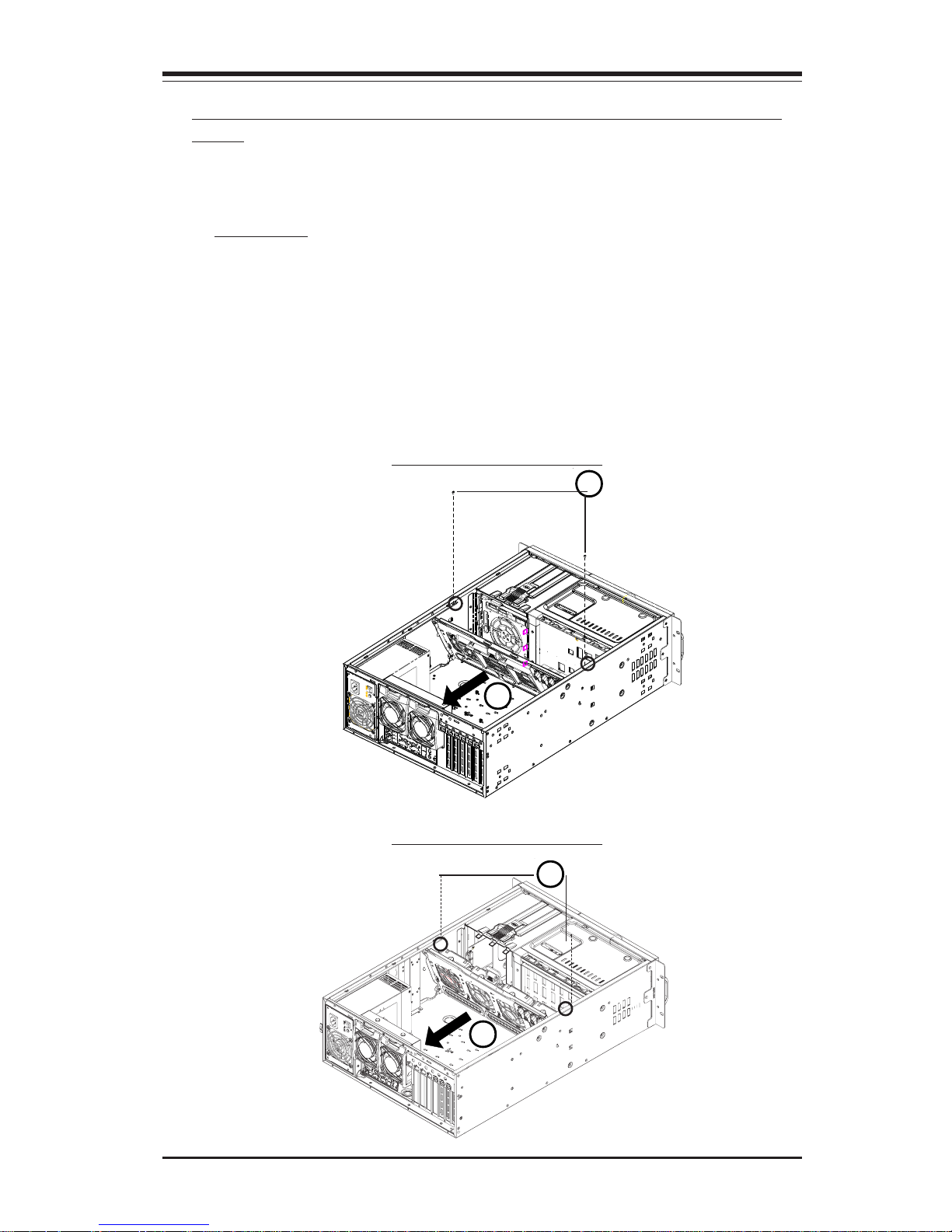
H. Access to the Interior between the Back Panel and the MidPlane
For easy access to the interior between the Back Panel and the Mid-plane,
please follow the instructions below before installing components or cables
into this area.
Procedures
1. Remove the two screws as shown in the picture below.
2. Remove the three screws on the bottom of the bracket between the Back
Panel and the Mid-plane.
3. Use a screw driver to gently press the release tabs to unlock the Mid-plane.
4. Pull the Mid-plane forward (about 350) as shown in the picture; then, you will
be able to easily access the interior between the Back Panel and the Midplane.
1
4
1
4
SC743 Chassis-Rev. A
SC743 Chassis-Rev. B
Page 34
2-16
SC743 Chassis User’s Guide
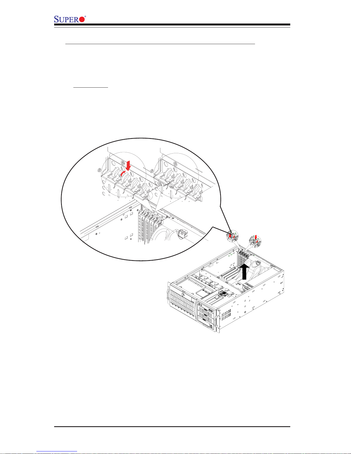
I. Accessing the PCI Slot Brackets to Install PCI Cards
AAa
Procedures
1. Locate the release tab on the top of PCI slot bracket.
2. Gently apply pressure at the middle of the release tab to unlock the PCI Slot
bracket as shown below:
After you've installed the motherboard into the chassis, you are ready to
install add-on cards, such as PCI cards into the chassis. Before installing PCI
cards, please follow the instructions below to access the PCI slot brackets.
3. Once the PCI slot bracket is unlocked, pull the release tab upward, and
remove the PCI slot bracket from the chassis.
4. Once the PCI slot bracket is removed from the chassis, you can install the
PCI Cards or other add-on cards into the PCI slot bracket.
5. Gently push the PCI slot bracket (with the PCI card or the add-on card
installed) into to the PCI slot and, then, push the middle of the blue button until
you hear the click as shown above. (*The click sound indicates that the PCI
bracket is securely locked into the chassis.)
Page 35

2-17
Chapter 2: Chassis Description and Installation Instructions
J. Accessing the Storage Module to Install 5.25" Devices, 3.5" Devices
or Mobile Racks
(Notes;
1. The storage module can accommodate up to three 5.25" devices such as
CD drives, IDE drives, DVD, tape drives and floppy drives as shown on this
page. You can use any combination of 5.25" devices (up to 3 drives) in this
module.
2. The storage module can also accommodate up to five 3.5" devices. To
configure the module for the use of 3.5" devices, you need to rotate the module
90 degrees as shown on the next page.
3. You can also simply rotate the storage module 90 degrees and install the
storage module back to the chassis in order to use the SC743 as a tower.
4. You can also install Supermicro's Mobile Rack CSE-M34T or Mobile Rack
CSE- M35S/T1 into the SC743 chassis. To do so, you need to simply remove
the storage module and replace it with a Mobile Rack. For Mobile Rack Information or Installation Instructions, please refer to Addendum A, and Addendum B.)
Page 36
2-18
SC743 Chassis User’s Guide
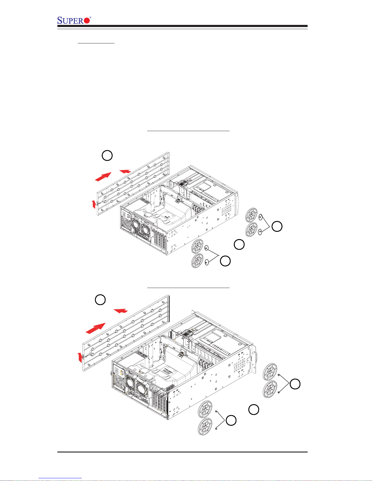
1. Push the buttons on the top cover to unlock it. Once it is unlocked, push the
top cover out of the chassis.
2. Remove the screw from each chassis foot.
3. Use a flat head screw driver to gently pry the chassis foot out of the chassis.
Procedures
1
2
2
3
SC743 Chassis-Rev. A
SC743 Chassis-Rev. B
132
2
Page 37
2-19
Chapter 2: Chassis Description and Installation Instructions
4
5
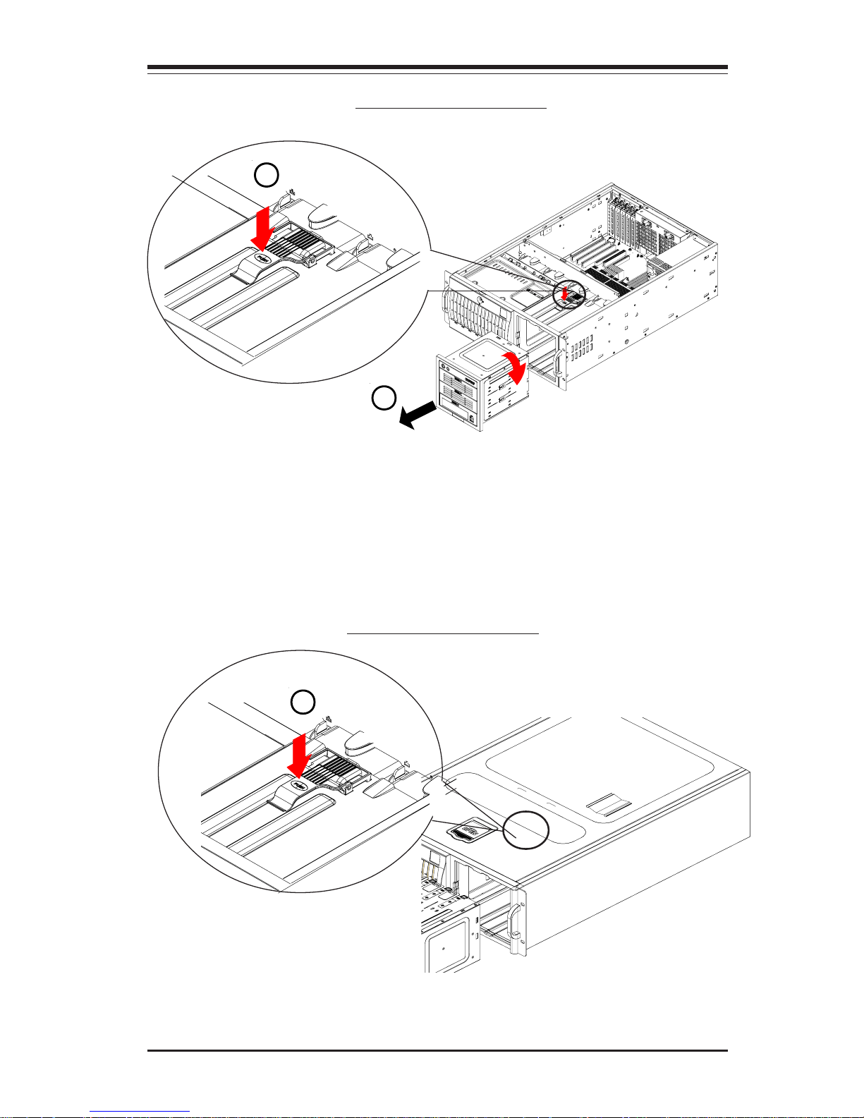
4. Locate the release tab on top of the storage module as shown below. Press
the release tab to unlock the storage module.
5. Once the storage module is unlocked, push the module out of the chassis.
SC743 Chassis-Rev. A
SC743 Chassis-Rev. B
4
Page 38
2-20
SC743 Chassis User’s Guide
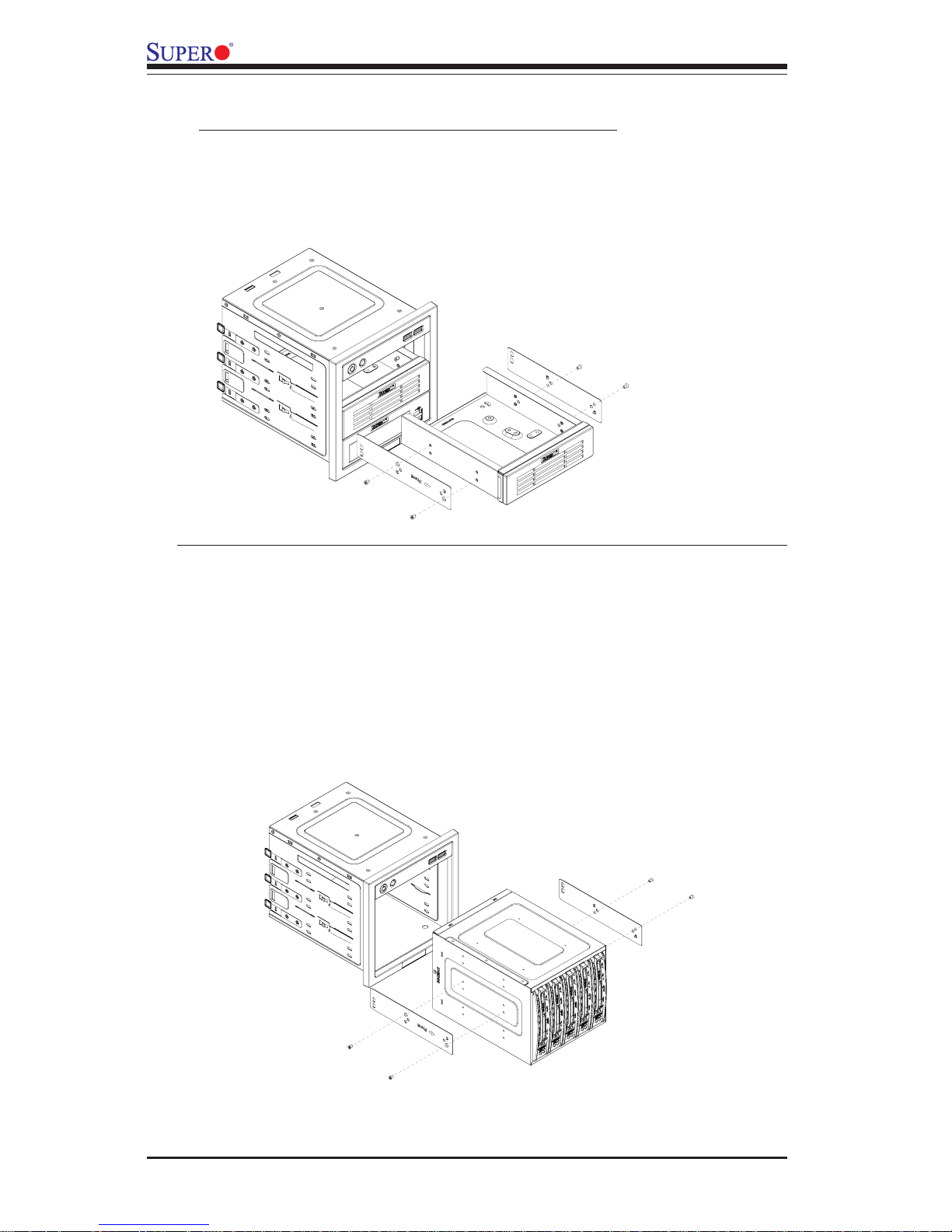
3. Remove the 5.25" drive trays from the storage module, and then, remove the
screws and drive tray brackets from the drive trays.
4. Install 5.25" devices into the storage module. Then, install the module back
to the chassis. Make sure that module is securely locked into the chassis.
To configure the storage module to support 3.5" devices or Mobile Racks
3. Remove the storage module from its housing, and then, remove the screws
and module brackets from the storage module.
4. Install 3.5" devices into the storage module. Securely attach the module
brackets to the storage module. (If a mobile rack is used, attach the brackets to
the mobile rack.)
5. Then, install the storage module (or the mobile rack) back to the chassis.
Make sure that module is securely locked into the chassis.
To configure the storage module for 5.25" devices
Page 39
2-21
Chapter 2: Chassis Description and Installation Instructions
Procedures
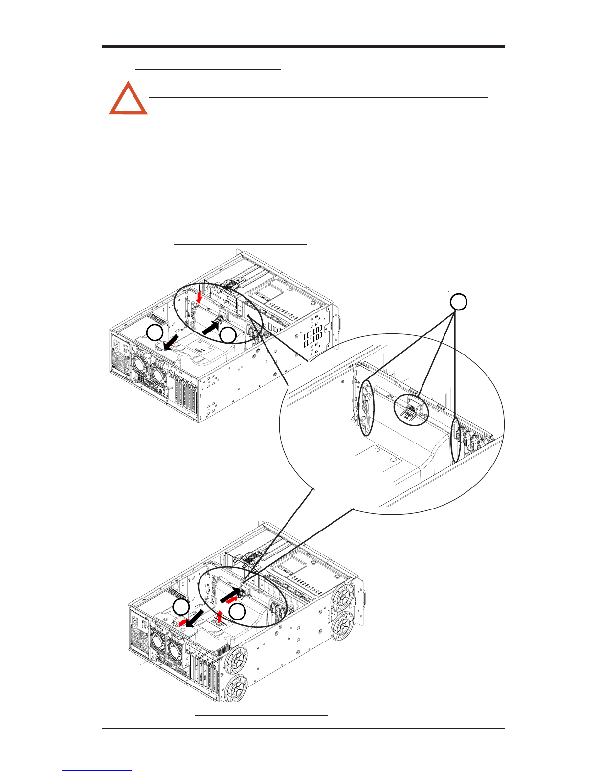
1. Locate the three guide rails on the reverse side of front fan panel as shown
below.
2. Align the air shroud with the guide rails and gently push the air shroud into the
chassis until both rear release tab and the front release tab are seated properly
and you hear the click.
Warning: For proper cooling, please be sure to install the air shroud
and all the chassis covers before you operate the system.
K. Installing the Air Shroud
1
2a
2b
SC743 Chassis-Rev. A
2a
2b
SC743 Chassis-Rev. B
!
Page 40
2-22
SC743 Chassis User’s Guide
L. Installing the Chassis Rails
Procedures to install inner rails on the chassis
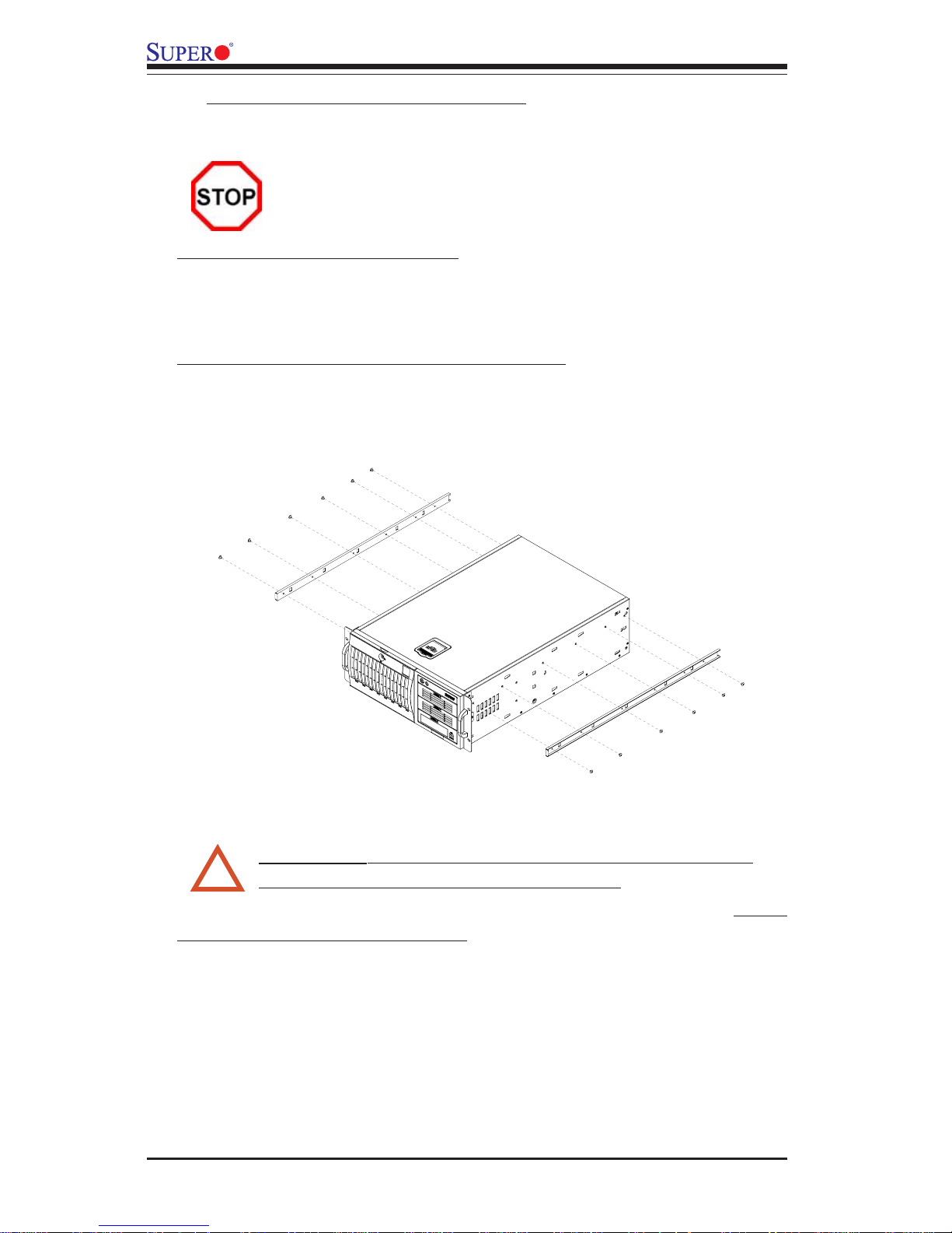
1. Locate a pair of inner rails and two sets of screws (6 screws-each set) that are
included in the shipping package, and align the inner rails against the top and the
bottom of the chassis as shown below:
Please make sure that the chassis covers and chassis rails are installed on the
chassis before you install the chassis into the rack.
To avoid personal injury and property damage, please carefully
follow all the safety steps listed below:
Before installing the Chassis rails:
1. Enclose the chassis with chassis covers.
2. Unplug the AC power cord(s).
3. Remove all external devices and connectors.
2. Install the inner rails onto the chassis by tightening the screws provided. Make
sure that the rails are flush against the edge of the chassis.
* The handles are for sliding the chassis in and out of the racks only. Do not
carry the chassis by the handles.
* Keep the area around the SC743 clean and free of clutter.
* To avoid injuries to your back, be sure to use your leg muscles, keep your back
straight, and bend your knees when lifting the system.
* After removing the components or chassis covers from the system, place them on
a table for safeguard.
* Avoid wearing loose clothing to preventing it from coming into contact with electrical
circuits or being pulled into a cooling fan.
!
Warning!! Follow the guidelines below to avoid possible
damage to the system or injury to yourself:
Page 41
2-23
Chapter 2: Chassis Description and Installation Instructions
Middle Rail
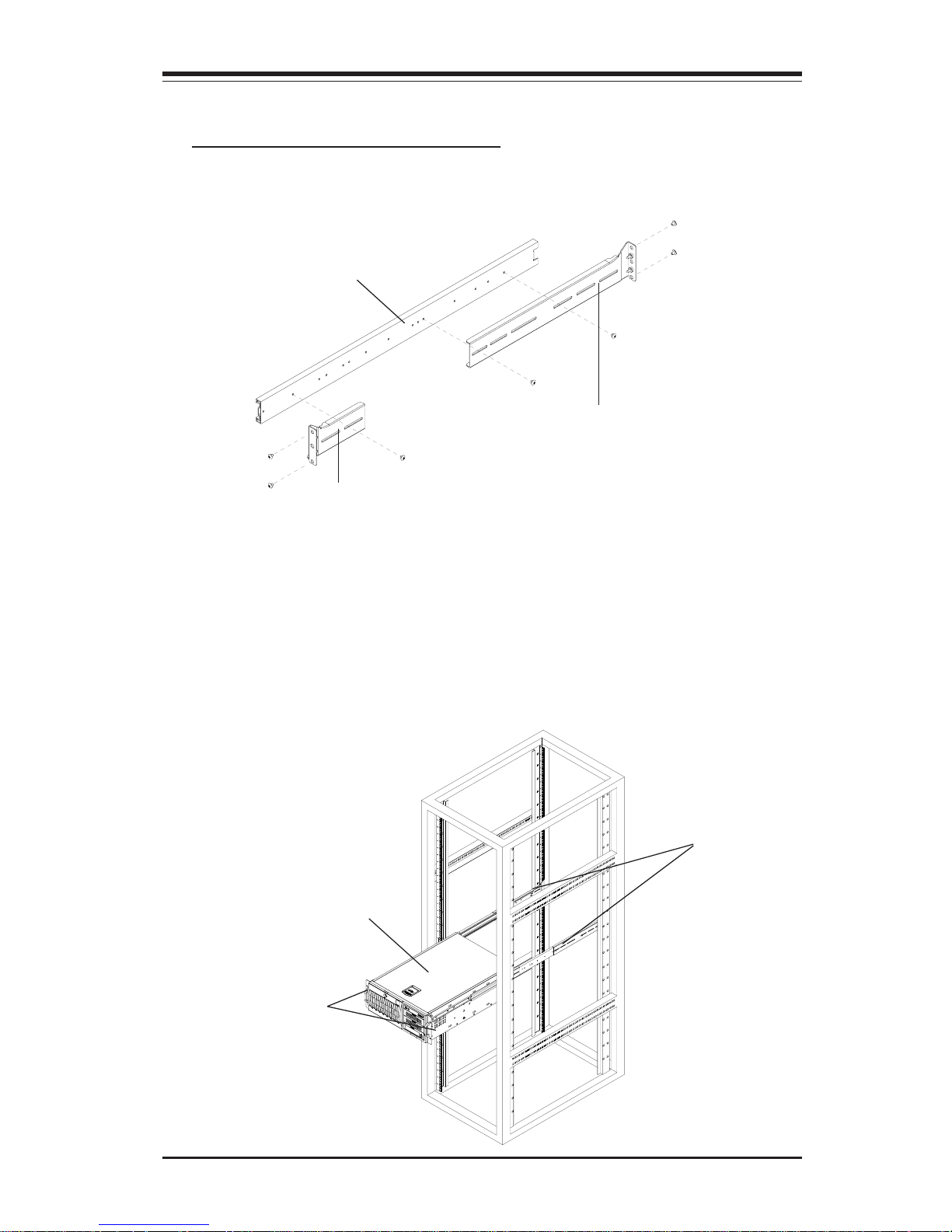
Procedures to Install the Outer Rails
2. Insert the end bracket and the end rail into the middle rail and secure the
outer rail assembly with screws.
3. Install a set of outer rail assembly to one side of the racks, and install another
set of outer rail assembly onto another side of the racks.
4. Insert the inner rails, which are attached to the SC743 chassis, into the
openings of the outer rail assemblies, and gently push the chassis into the
racks. Make sure that the chassis is properly and securely installed in the racks.
1. Locate two pairs of outer rails--each pair of outer e rails consist of one middle
rail, one end bracket and one end rail as shown below:
End Bracket
End Rail
Outer Rail
Assemblies
Inner Rails
SC743
Chassis
Page 42

2-24
SC743 Chassis User’s Guide
Notes
Page 43
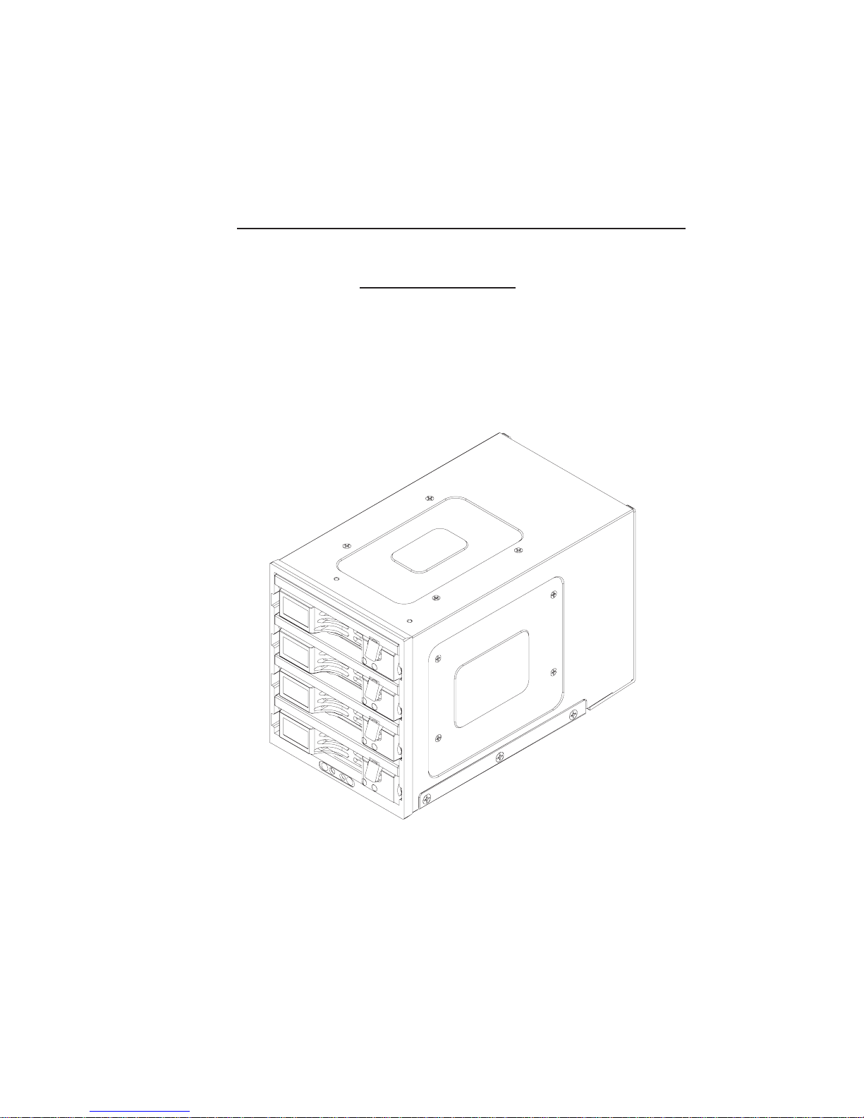
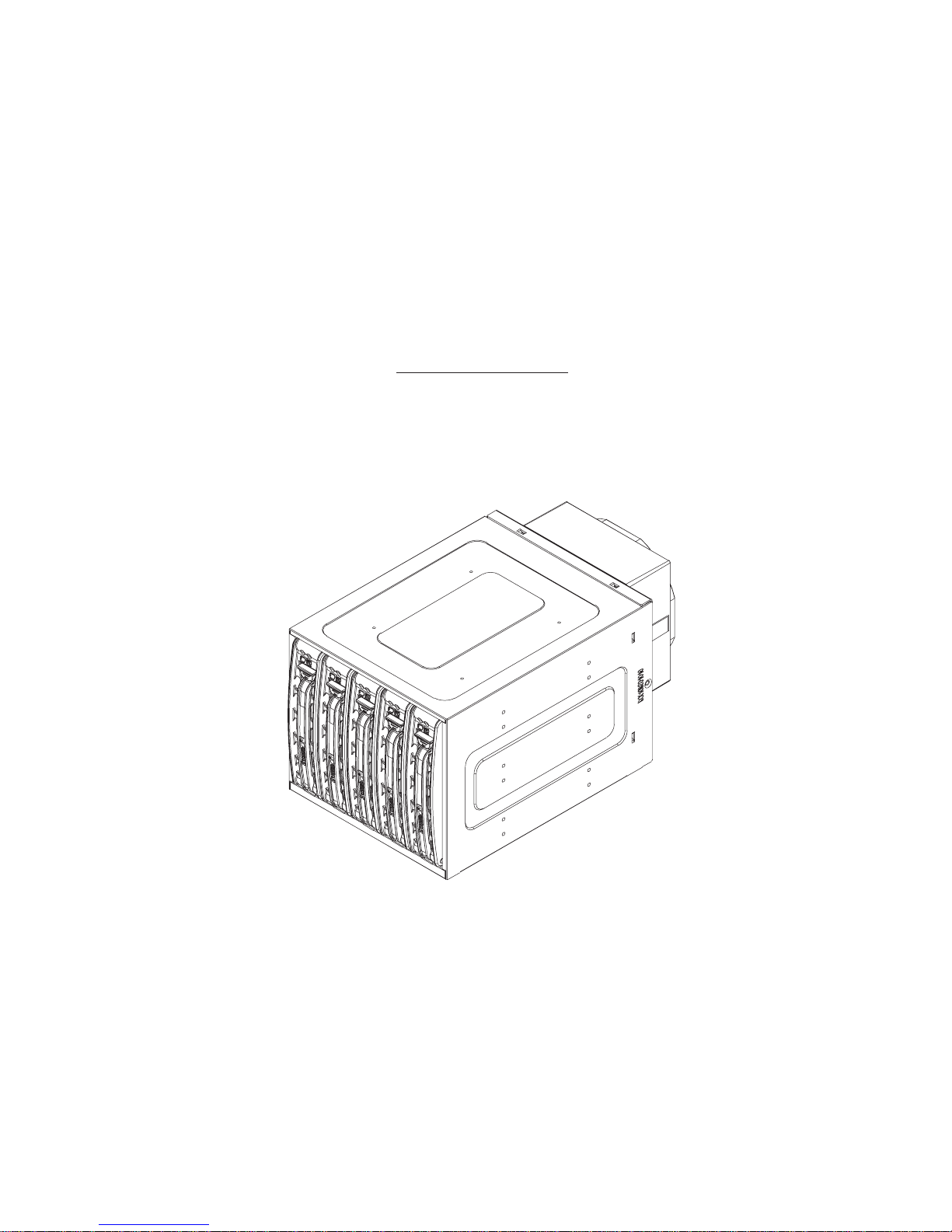
Mobile Rack
Installing the CSE-M34S/CSE-M34T
Addendum A:
Page 44

SC743 Chassis User's Guide
A-2
Table of Contents
1. Packaging List ....................................................................................................3
2. Technical Specifications...................................................................................3
3. Jumper Settings .................................................................................................4
4. Hardware Installation Procedures ................................................................ 6
5. SCSI(Super) GEM Drive Installation Instructions for Windows OS ..........8
Page 45
A-3
Addendum A: Installing Mobile Rack-CSE M34S/T
CSE-M34S/CSE-M34T
Supermicro’s CSE-M34S/CSE-M34T Mobile Rack Series offers the cutting
edge technology with greater flexibility. The CSE-M34T supports four Serial
ATA hot-swap hard drives that yield an unparalleled storage capacity without compromising productivity by eliminating possible system downtime. The
CSE-M34S also accommodates four SCSI SCA 320/160 hard drives which
provide configuration flexibility and maximum data integrity.
1. Packing List
Please check to see if you have received all the items listed below:
*CSE-M34S/CSE-M34T Mobile Rack
*90mm-Exhaust Fan
*Screws: Six (6) counts of 6-32 hex washer head screws
Eight (8) counts of M3 washer head screws
Eighteen (18 )counts of Pan head screws
*Drive Carrier Four (4)CSE-PT10 (-beige only)
(*For the CSE-M34T only)
*Serial ATA Backplane (CSESATA-M34)
*Four (4) Serial ATA Cables (CBL-0044)
*Serial ATA LED cable (CBL-0057)
*SCSI cable (CBL-027-U320)
*SCSI Backplane (CSESCA-002)
(*For the CSE-M34S only)
2. Technical Specifications
Chassis supported:
SC743
Occupancy Three (3) 5.25" Drive Bays
Capacity Four (4) 1" SCA Ultra320/160 Hard Drives with
SAF-TE built-in (*CSE-M34S only)
Four (4) 1" Host Receptacle Connectors, SATA
hot-swap hard drives (*CSE-M34Tonly)
Cooling
Subsystem
One (1) 90mm Exhaust Fan
System
Monitoring
Fan Fail Detection LED and Alarm
Overheat LED indication
Built-in Termination (*CSE-M34S only)
Dimension
(WxHxD)
147mm x 129mm x 230mm
(5.8 in x 5.0 in x 9.1 in)
Weight Gross: 6.8lb (3.4 kg)
Page 46
SC743 Chassis User's Guide
A-4
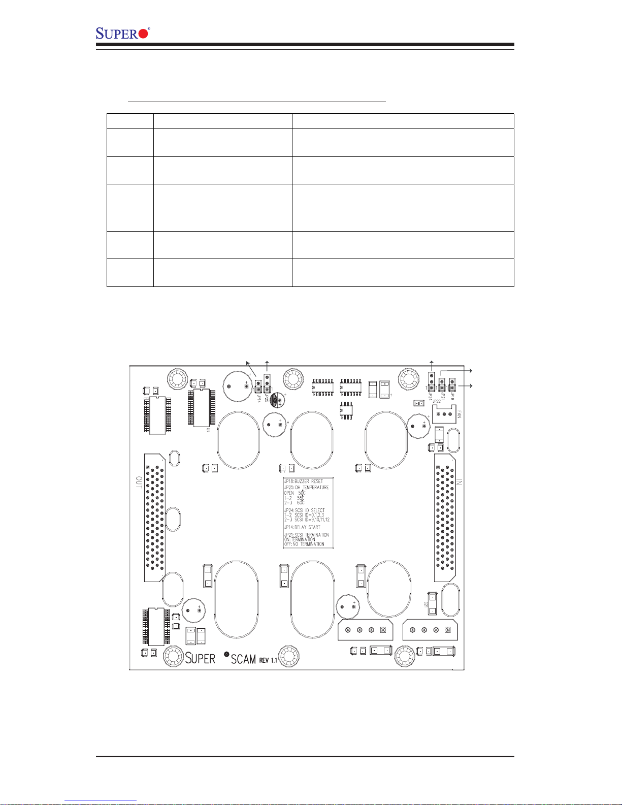
3. Jumper Settings
A. Jumper Settings for the CSE-M34S (SCSI):
Jumper Locations
JP18
JP21
JP24
JP14
JP25
Jumper Description Setting
JP14 Delay Start Closed: Enable,
Open: Disable (*Default)
JP18 Buzzer Reset Closed: Enable,
Open: Disable (*Default)
JP25 Overheat Temperature
Open: 50
o
C
1-2: 55
o
C (*Default)
2-3: 60
o
C
JP21 SCSI Termination Closed: Enable (*Default),
Open: Disable
JP24 SCSI ID Selection 1-2: SCSI IDs:0,1,2,3,4 (*Default)
2-3: SCSI IDs:9,10,11,12,13
Page 47
A-5
Addendum A: Installing Mobile Rack-CSE M34S/T
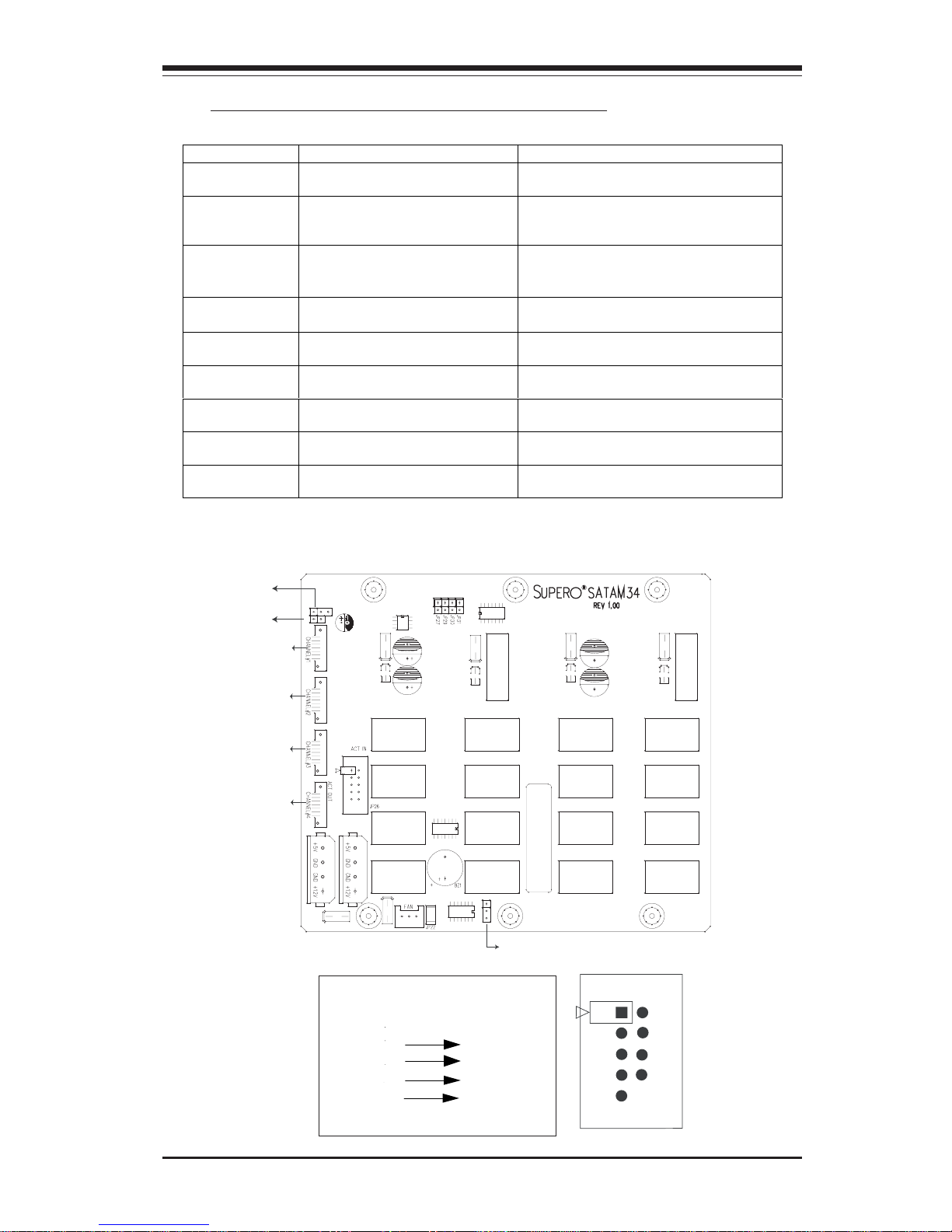
B. Jumper Settings for the CSE-M34T (SATA):
Jumper Locations
Act. LED 1
Act. LED 2
Act. LED 3
Act. LED 4
Channel 1
Channel 2
Channel 3
Channel 4
Activity LEDs
-
Pin Definition
s
JP26
JP18
JP25
Channel #2
Channel #3
Channel #4
Channel #1
JP28
Jumper Description Setting
JP18
Buzzer Reset
Closed: Enable,
Open: Disable (*Default)
JP25
Overheat Temperature
Open: 45OC
1-2: 50
O
C (*Default)
2-3: 55
O
C
JP28 Fan Sense 1-2: Enabled (if a fan is not present,
the alarm will sound) (*Default),
2-3: Disabled
JP26 Common Act#1-Act#4 Connect this header to CBL-0057
(SATA LED Cable)
JP27 Common Act In-Act#1
Closed: Enable,
Open: Disable (*Default)
JP29 Common Act In-Act#2
Closed: Enable,
Open: Disable (*Default)
JP30 Common Act In-Act#3
Closed: Enable,
Open: Disable (*Default)
JP31 Common Act In-Act#4
Closed: Enable,
Open: Disable (*Default)
JP32 Common Act Out
Closed: Enable,
Open: Disable (*Default)
ACT2
ACT3
ACT4
COM
Key
JP26
ACT1
Page 48
SC743 Chassis User's Guide
A-6
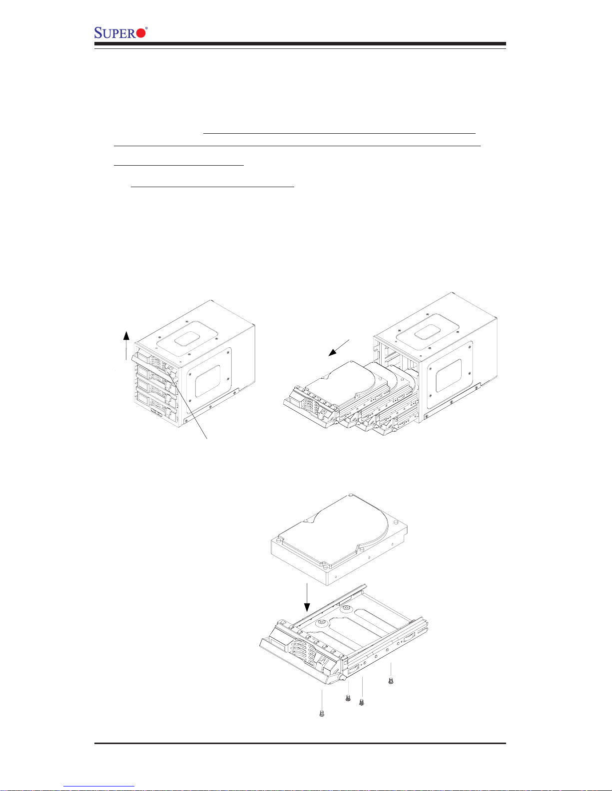
A. Accessing Hot Swap Drives:
1. Push the release button and pull up the handle to release the
drive tray as shown below on the left:
4. Hardware Installation Procedures
(*Notes: For the CSE-M34S: 1. SCSI IDs are assigned automatically by the
backplane. Do not set IDs manually on the drives. See the previous section
for SCSI ID jumper settings. 2. SCSI termination is enabled by default on the
SCSI backplane. 3. To install the CSE-M34 Mobile Rack into the SC743
chassis, please refer to Chapter 2 Section J on Page 2-17 to 2-19 for
installation instructions.)
Push the release button
Pull up the
handle
2. Pull out drive trays as shown below on the right:
3. Mount a drive in a carrier and secure it with screws as shown
below:
Mount a drive
into a carrier
Secure the drive
with screws
Pull up the
drive trays
Page 49
A-7
Addendum A: Installing Mobile Rack-CSE M34S/T
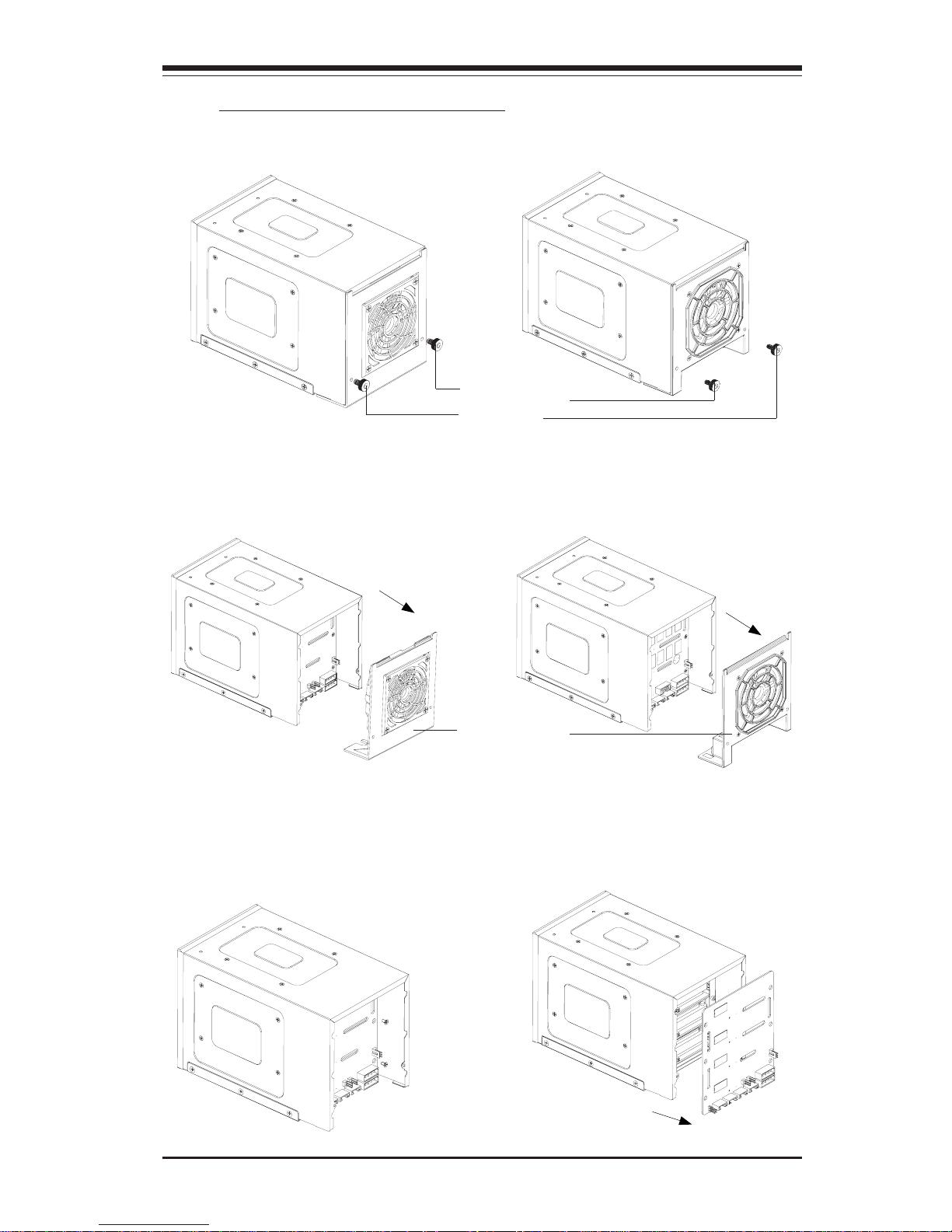
3. Remove the six backplane screws and access the backplane as
shown below:
Remove the screws Access the backplane
2. Pull out the rear fan bracket as shown below:
The CSE-M34T(SATA) Model
The CSE-M34S(SCSI) Model
Pull out the rear
fan bracket
B. Accessing the Drive Backplane:
1. Remove the two screws as shown below:
The CSE-M34T (SATA) Model The CSE-M34S(SCSI) Model
Remove the
screws
Page 50

SC743 Chassis User's Guide
A-8
5. SCSI (Super) GEM Driver Installation Instructions for
Windows OS
Please refer to the following instructions to install the SCSI GEM
Driver for the Windows OS systems.
(*Note: This driver is not necessary for other Operating Systems. If you
have two SCA backplanes, you will need to install the driver twice.)
The driver is located on the Super Micro motherboard driver CD or is available
for download from our ftp site: ftp://ftp.supermicro.com/driver/Qlogic/
Follow the procedure below to install this driver to your system.
Installing the driver:
1) Right click on “My Computer” and choose “Property”.
2) Select “Hardware” tab and click on “Device Manager”.
3) Open “Other Devices” or wherever “GEM318” is on.
4) Right click on this device and choose “Property”.
5) Click on “Driver” tab and choose “Update Driver”.
6) Click “Next” 2 times, uncheck both “Floppy disk drives” and “CD-ROM
drives”. Then, select the item- “Specify a location,” and choose “Next”.
7) Click on “Browse” and choose D drive or wherever Supermicro Setup CD
is in.
8) Choose “Qlogic” folder and click on “Open”.
9) System will automatically detect GEM318 and install the drive from this
point on.
or,
1) Right click the "My Computer" icon on your desktop and choose Properties.
2) Click on the Hardware tab and click on "Device Manager" to bring up the
list of system devices.
3) You may see one or two yellow question marks (?) that read QLogic
GEM354 or GEM318 SCSI Processor Device. Right click on these, and
choose to uninstall. If two such question marks are present, uninstall both.
4) Click on Action tab and choose "Scan for Hardware Changes". The
Hardware Wizard program should start up. Click "Next".
5) At the first prompt, choose “Display a list of known device drivers for the
device so that I can choose a specific driver” and click "Next".
6) Choose “Other Devices” and click Next.
7) Choose “Have Disk”, and specify your floppy drive location in the options
box. Then, click "Next".
8) Highlight “Enclosure Services Device” and click "Next".
9) Ignore the warning prompt by clicking "Yes".
Page 51
Mobile Rack
Installing the CSE-M35S/CSE-
M35T1
Addendum B
Page 52

SC743 Chassis User's Guide
B-2
Table of Contents
1. Packaging List ......................................................................................................3
2. Technical Specifications ....................................................................................4
3. Jumper Settings ................................................................................................... 5
4. Installation Procedures ..................................................................................... 7
Page 53

B-3
Addendum B: Installing Mobile Rack-CSE M35S/T1
CSE-M35S/CSE-M35T1
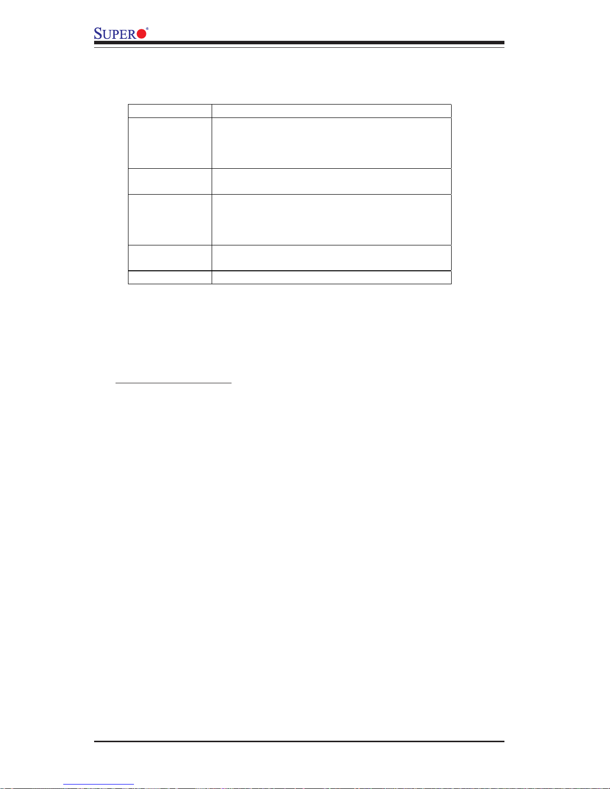
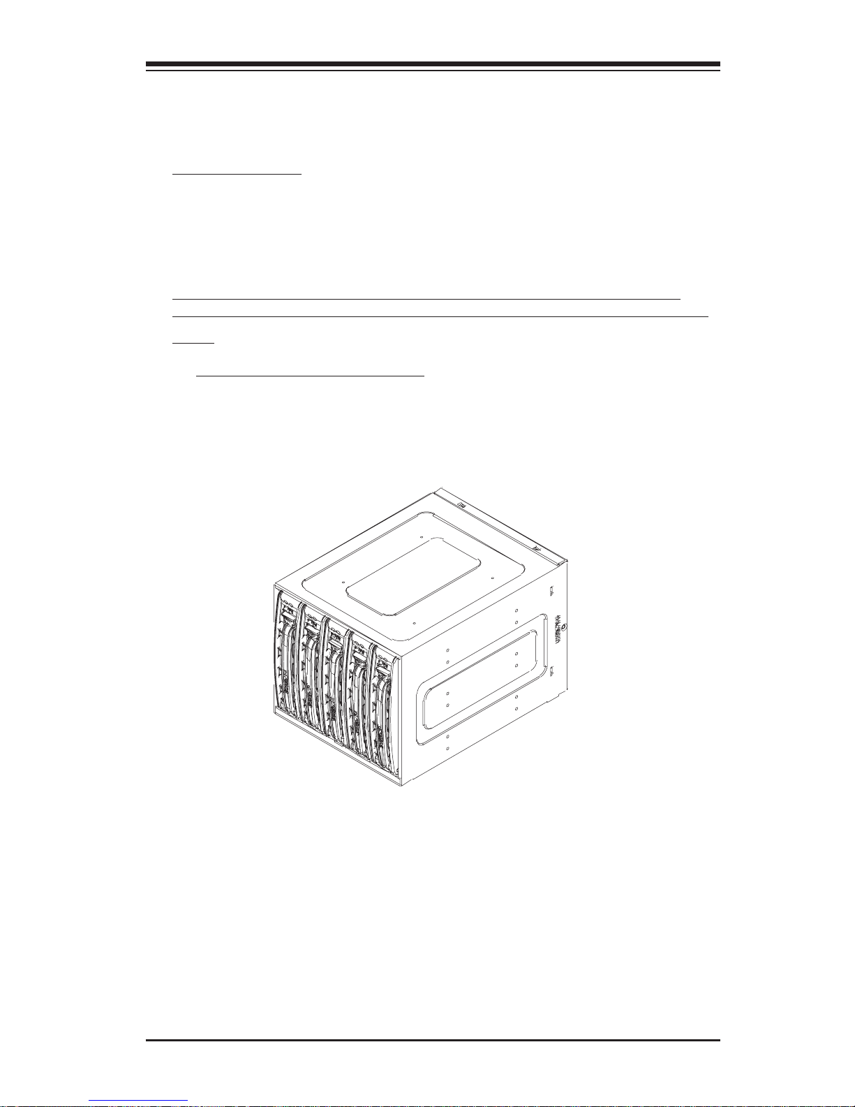
Supermicro’s CSE-M35S/CSE-M35T1 Mobile Rack Series offers the cutting
edge technology with greater flexibility. The CSE-M35T1 supports five Serial ATA hot-swappable hard drives that yield a unparalleled storage capacity without compromising productivity by eliminating possible system downtime. The CSE-M35S also accommodates five SCSI SCA 320/160 Hard
drives which provide configuration flexibility and maximum data integrity.
1. Packing List
Please check to see if you have received all the items listed below:
*CSE-M35S/CSE-M35T1 Mobile Rack
*90mm-Exhaust Fan (Fan-0057)
*Screws: Thirteen (13) counts of Flat Head Screws
Twenty-four (24) counts of Round Head Screws
Seven (7) counts of Round Head Screws with Lock-Washer
*Drive Carrier Five (5)CSE-PT17/CSE-PT17(B)(-black)
(*For the CSE-M35T1 only)
*Serial ATA Backplane (CSE-SATAM35)
*Five (5) Serial ATA Cables (CBL-0044)
*Serial ATA LED cable (CBL-0057)
*SCSI cable (CBL-027-U320)
*SCSI Backplane (CSE-SCAM743)
(*For the CSE-M35S only)
Page 54
SC743 Chassis User's Guide
B-4
2. Technical Specifications
Occupancy
Three (3) 5.25" Drive Bays
Capacity
Five (5) 1" SCA Ultra320/160 Hard Drives with SAF-TE
built-in (*CSE-M35S only)
Five (5) 1" Host Receptacle Connectors, SATA hot-swap
hard drives (*CSE-M35T-1 only)
Cooling
Subsystem
One (1) 9cm Exhaust Fan
System
Monitoring
Fan Fail Detection LED and Alarm
Overheat LED indication
Drive Fail Alarm and Indication (*CSE-M35S only)
Built-in Termination (*CSE-M35S only)
Dimension
(WxHxD)
146mm x 129mm x 245mm
(5.7 in x 5.0 in x 9.6 in)
Weight
Net: 5.9lb (2.9 kg), Gross: 7.5lb (3.7 kg)
Chassis supported:
SC743
Page 55
B-5
Addendum B: Installing Mobile Rack-CSE M35S/T1
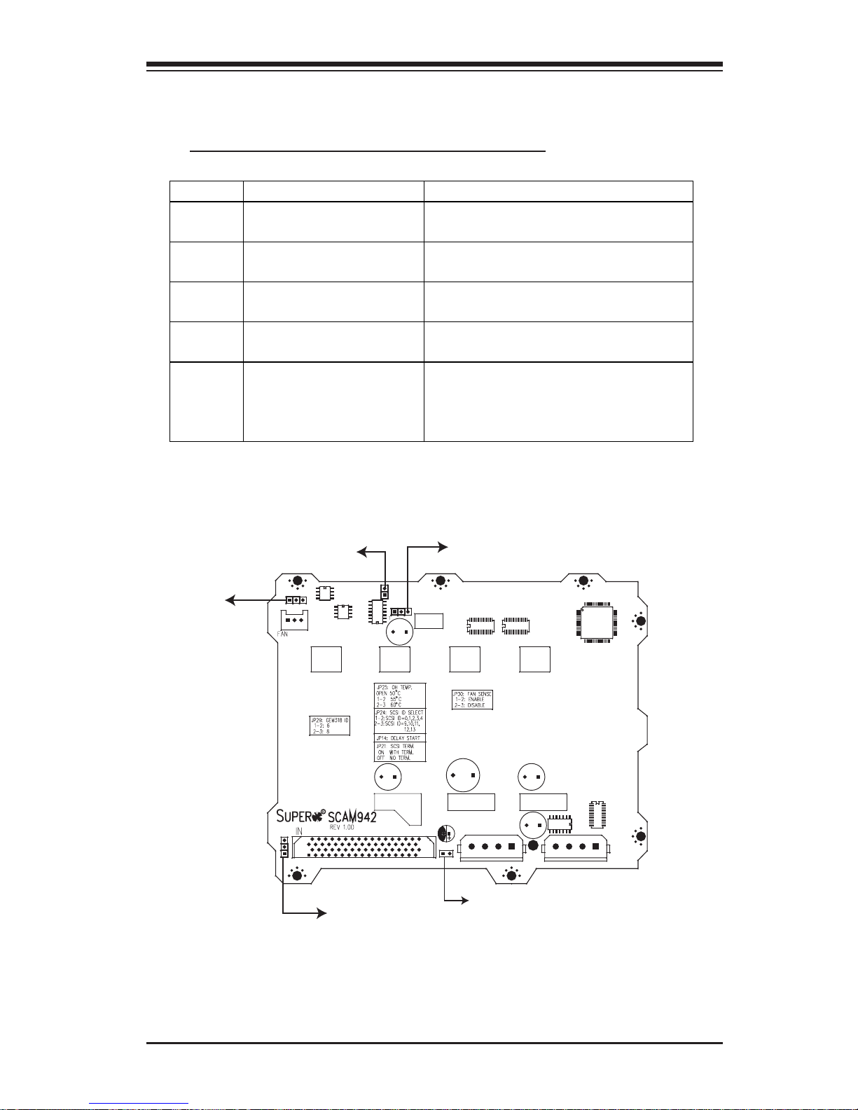
3. Jumper Settings
A. Jumper Settings for the CSE-M35S (SCSI):
Location of Jumpers
Jumper Description Setting
JP18 Buzzer Reset Closed: Enable,
Open: Disable (*Default)
JP21 SCSI Termination Closed: Enable (*Default),
Open: Disable
JP24 SCSI ID Selection 1-2: SCSI Ids: 0,1,2,3,4 (*Default),
2-3: SCSI Ids: 9,10,11,12,13
JP29 GEM 318 IDs 1-2: ID6 (*Default),
2-3: ID8
JP30 Fan Sense Pins 1-2: Enable (*Default) (If a fan
is not present, the alarm will
sound.),
Pins 2-3: Disable
J
P29
JP21
JP30
JP18
JP24
Pin 1
Pin 1
Pin 1
Pin 1
Pin 1
Page 56
SC743 Chassis User's Guide
B-6
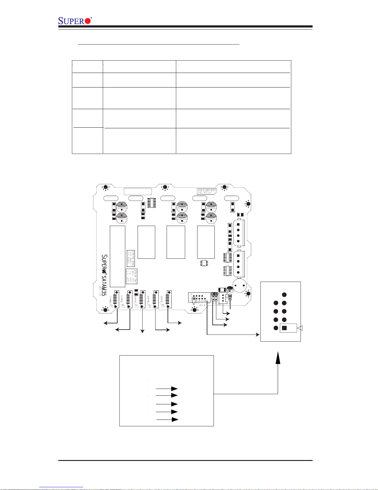
B. Jumper Settings for the CSE-M35T1 (SATA):
Location of Jumpers
JP28
JP25
JP18
C
hannel #1
Channel #2
ACT5
FAN
Channel #3
Channel #4
Channel #5
ACT6
ACT7
ACT8
ACT1
ACT2
ACT3
ACT4
COM
Pin 1
Pin 1
Key
JP26
Activity LEDs-
Pin Definitions
Act. LED 1
Act. LED 2
Act. LED 3
Act. LED 4
Act. LED 5
Channel 1
Channel 2
Channel 3
Channel 4
Channel 5
Jumper Description Setting
JP18 Buzzer Reset Closed: Enable,
Open: Disable (*Default)
JP25 Overheat Temperature Open: 45OC
1-2: 50
O
C (*Default),
2-3: 55
O
C
(SATA LED Cable)
JP28:
Fan Sense 1-2: Enabled (if a fan is not present,
the alarm will sound) (*Default)
2-3: Disabled
JP26
Act#1-Act#5 Connect this header to CBL-0057
Page 57
B-7
Addendum B: Installing Mobile Rack-CSE M35S/T1
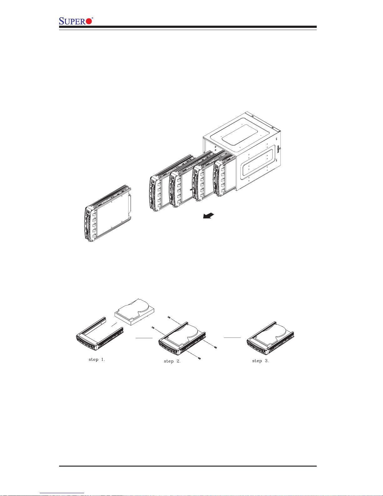
A. Accessing Hot Swap Drives:
1. Push the release button located beside the drive LEDs (as
shown below:)
4. Installation Procedures
(*Note:
For the CSE-M35S:
1. SCSI IDs are assigned automatically by the backplane. Do not set IDs
manually on the drives. See the previous section for SCSI ID jumper settings.
2. SCSI termination is enabled by default on the SCSI backplane.
3. To install the CSE-M35 Mobile Rack into the SC743 chassis, please
refer to Chapter 2 Section J on Page 2-17 to 2-19 for installation instruc-
tions.
Page 58
SC743 Chassis User's Guide
B-8
3. Mount a drive in a carrier (as shown below:)
2. Swing the handle outward and pull out the unit (as shown below:)
Page 59
B-9
Addendum B: Installing Mobile Rack-CSE M35S/T1
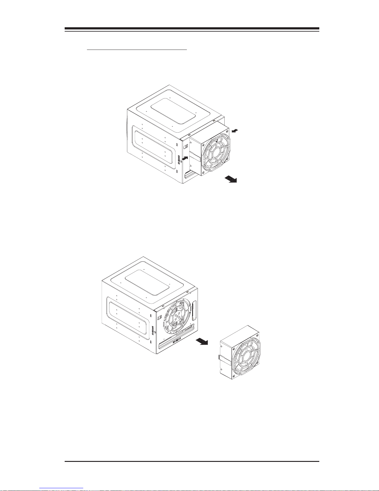
B. Accessing the Exhaust Fan:
1. Push the tabs located on both sides of the unit (as shown below:)
2. Pull out the fan (as shown below:)
(*Note: For the SC-743 Chassis, the CSE-M35 Rear Exhaust Fan
should not be used. Instead, the hot-swap 120mm Chassis Fans
included with the SC-743 Chassis should be connected to the Backplane of the CSE-M35S/CSE-M35T1 Mobile Rack.)
Page 60
SC743 Chassis User's Guide
B-10
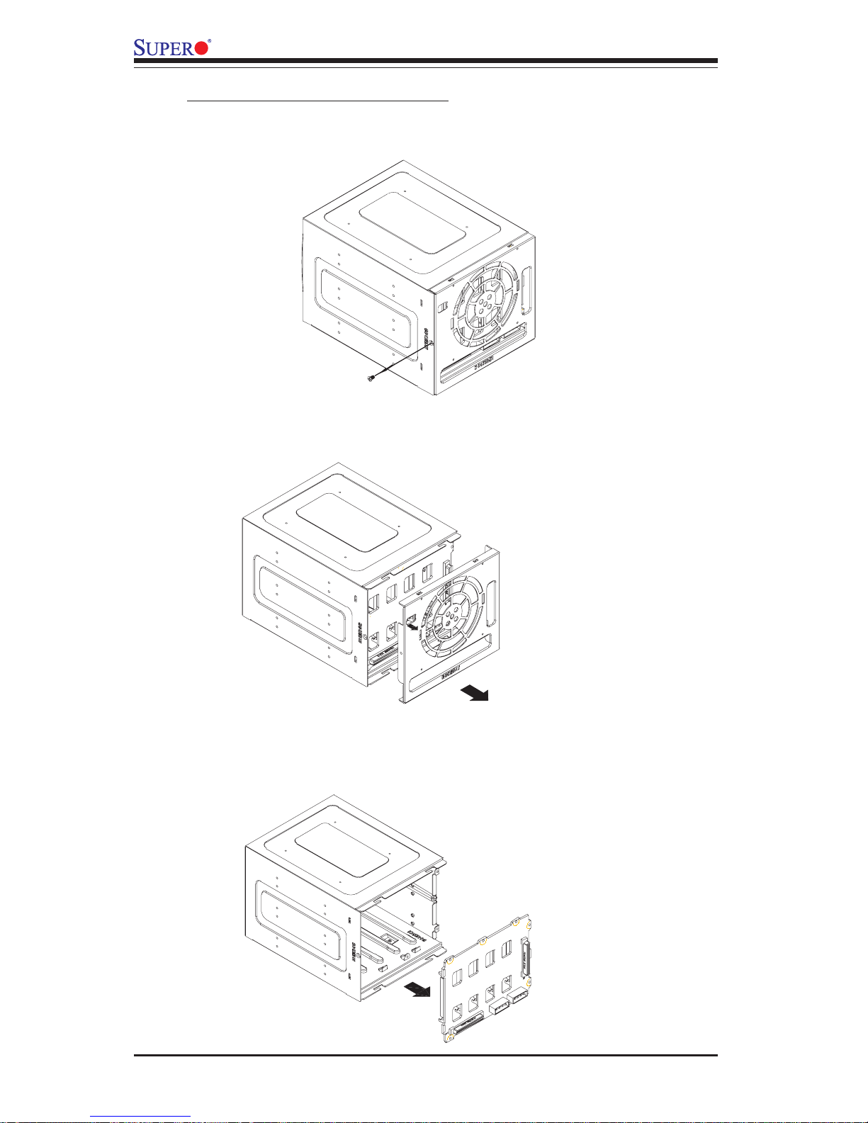
C. Accessing the Drive Backplane:
1. Unscrew the screw located on the side of the unit (as shown
below:)
2. Pull out the Rear Bracket (as shown below:)
3. Access the Backplane (as shown below:)
 Loading...