

SUPER
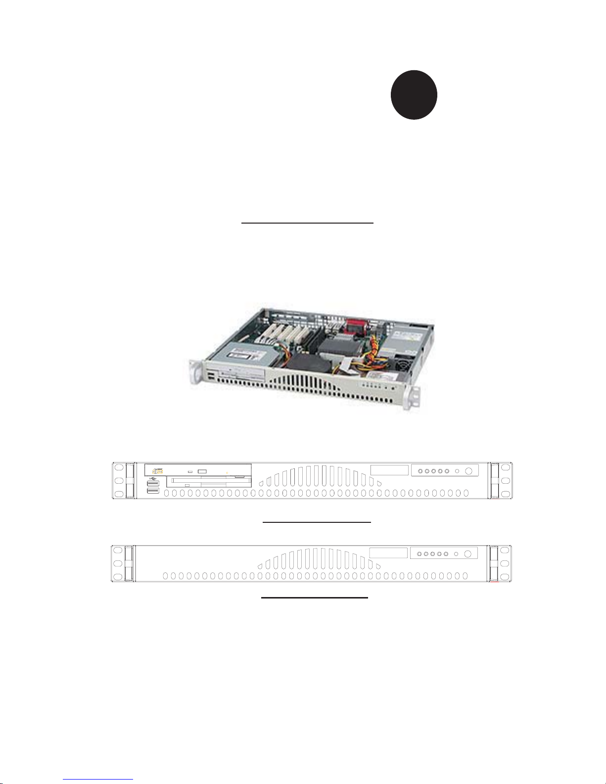
The SC512C/L Series
®
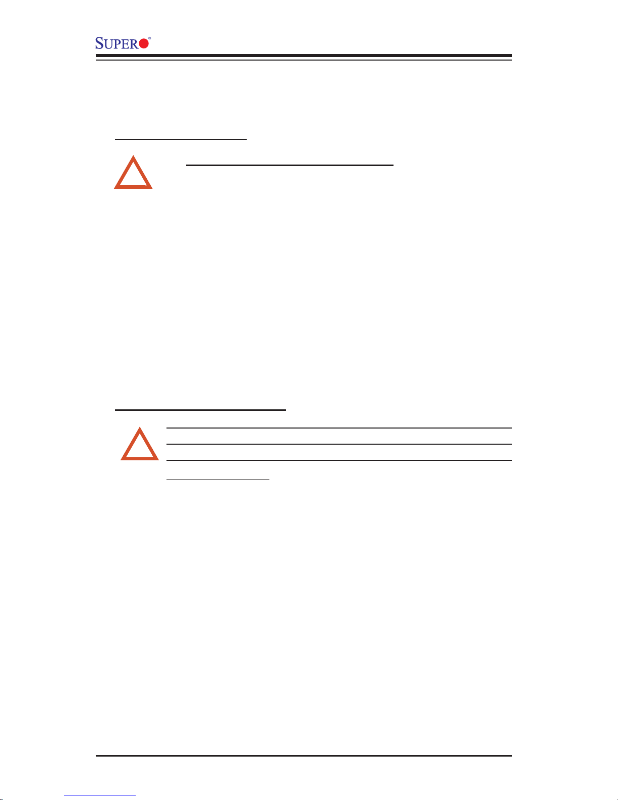
The SC512C Series
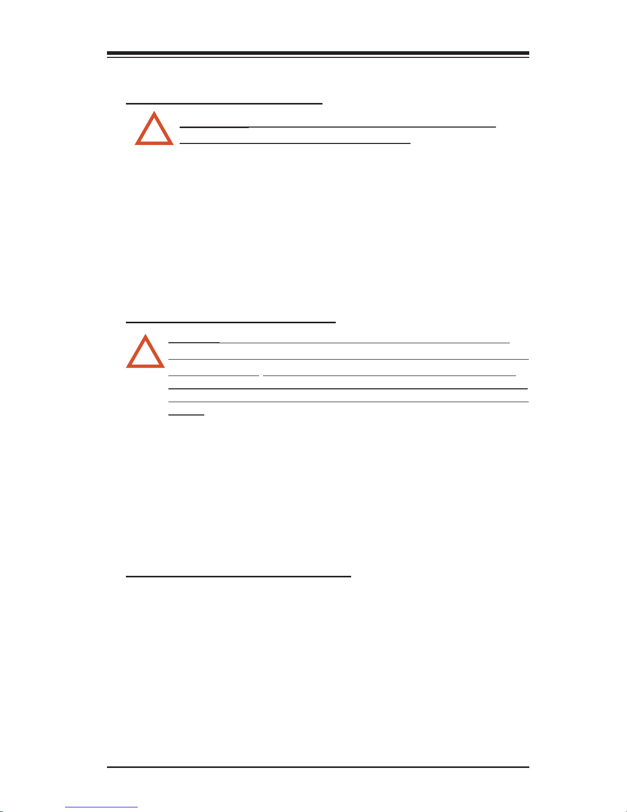
The SC512L Series
SC512 CHASSIS
USER'S GUIDE
1.0

SC512 Chassis User’s Guide
The information in this User’s Guide has been carefully reviewed and is believed to be accurate.
The vendor assumes no responsibility for any inaccuracies that may be contained in this document,
makes no commitment to update or to keep current the information in this manual, or to notify any
person or organization of the updates.
Please Note: For the most up-to-date version of this manual, please see our web
site at www.supermicro.com.
SUPERMICRO COMPUTER reserves the right to make changes to the product described in this
manual at any time and without notice. This product, including software, if any, and documentation may not, in whole or in part, be copied, photocopied, reproduced, translated or reduced to any
medium or machine without prior written consent.
IN NO EVENT WILL SUPERMICRO COMPUTER BE LIABLE FOR DIRECT, INDIRECT, SPECIAL,
INCIDENTAL, OR CONSEQUENTIAL DAMAGES ARISING FROM THE USE OR INABILITY TO
USE THIS PRODUCT OR DOCUMENTATION, EVEN IF ADVISED OF THE POSSIBILITY OF
SUCH DAMAGES. IN PARTICULAR, THE VENDOR SHALL NOT HAVE LIABILITY FOR ANY
HARDWARE, SOFTWARE, OR DATA STORED OR USED WITH THE PRODUCT, INCLUDING THE
COSTS OF REPAIRING, REPLACING, INTEGRATING, INSTALLING OR RECOVERING SUCH
HARDWARE, SOFTWARE, OR DATA.
Any disputes arising between manufacturer and customer shall be governed by the laws of Santa
Clara County in the State of California, USA. The State of California, County of Santa Clara shall
be the exclusive venue for the resolution of any such disputes. Supermicro's total liability for all
claims will not exceed the price paid for the hardware product.
Manual Revision: Rev. 1.0
Release Date: June 15, 2006
Unless you request and receive written permission from SUPER MICRO COMPUTER, you may not
copy any part of this document.
Information in this document is subject to change without notice. Other products and companies
referred to herein are trademarks or registered trademarks of their respective companies or mark
holders.
Copyright © 2006 by SUPER MICRO COMPUTER INC.
All rights reserved.
Printed in the United States of America
1-2

Chapter 1: Safety Information and Technical Specifi cations
Table of Contents
Chapter I: Safety Information and Technical Specifi cations ................ 1-4
1-1. Electrical Safety Guidelines ............................................................................ 1-4
1-2. ESD Safety Guidelines ..................................................................................... 1-4
1-3. General Safety Guidelines ............................................................................... 1-5
1-4. Operation Safety Guidelines ........................................................................... 1-5
1-5. An Important Note to the User ....................................................................... 1-5
1-6. Product Compliance Information ................................................................... 1-6
1-7. Packing List and the SC512 Specifi cations ................................................. 1-7
A. The SC512 Chassis ............................................................................................... 1-7
B. The Accessory Kit .................................................................................................. 1-8
C. Chassis Specifi cations .......................................................................................... 1-8
D. Power Supply Specifi cations ................................................................................ 1-8
Chapter 2: Chassis Description and Installation Procedures .............. 2-1
2-1. Chassis Description ........................................................................................ 2-1
A. Contents of the Accessory Kit ............................................................................... 2-1
B. Power Cords/SATA Cables .................................................................................... 2-1
C. Chassis Front View and the Front Control Panel ................................................ 2-2
D. Chassis Rear View and the Back Panel .............................................................. 2-3
2-2. Chassis Installation ........................................................................................ 2-4
A. Important Safety Guidelines .................................................................................. 2-4
B. Tools Needed ......................................................................................................... 2-4
C. Removing the Top Chassis Cover and the HDD Tray Bracket ............................. 2-5
D1. Removing the CD-ROM Module .......................................................................... 2-6
D2. Removing the HDD Drive Tray Housing and Installing the HDDs ...................... 2-7
E Installing the Motherboard ..................................................................................... 2-8
F. Installing and Un-installing the Heatsink Mechanism ............................................ 2-9
G. Installing the Cooling Fan Module and the Air Shroud ....................................... 2-10
H. Installing Chassis Rails ..................................................................................... 2-11
I-1. Installing the Traditional UP Racks .................................................................... 2-13
I-2. Installing the Open Racks .................................................................................. 2-15
J. Installing the SC512 Chassis into the Racks ....................................................... 2-18
1-3
SC512 Chassis User’s Guide
Chapter 1- Introduction
1-1 Electricity Safety
General Electrical Safety Guidelines
Use the exact type of power cords as required.
!
•
Be sure to use power cord(s) that came with safety certifi ca-
•
tions.
The power cord(s) must be compliant with the AC voltage require-
•
ments in your region.
Plug the Power cord(s) into a socket that is properly grounded
•
before turning on the power.
Take extra precautionary measures when working with high voltage
•
components. It is not recommended to work alone.
Before removing or installing chassis components, be sure to
•
disconnect the power fi rst. Turn off the system before you dis-
connect the power supply.
1-2. ESD Safety Guidelines
Electric Static Discharge (ESD) can damage electronic com ponents. To
prevent damage to your system board, it is important to handle it very
!
carefully. The following measures are generally suffi cient to protect your
equipment from ESD.
Use a grounded wrist strap designed to prevent static discharge.
•
Keep all components and printed circuit boards (PCBs) in their antistatic bags
•
until ready for use.
Touch a grounded metal object before removing chassis components or the
•
motherboard from the antistatic bag.
Do not let components or PCBs come into contact with your clothing, which
•
may retain a charge even if you are wearing a wrist strap.
Handle a motherboard by its edges only; do not touch its components, peripheral
•
chips, memory modules or contacts.
When handling processors, chips or modules, avoid touching their pins.
•
Put the motherboard or components back into their antistatic bags when not
•
in use.
For the grounding purpose, make sure that your chassis provides excellent
•
conductivity between the power supply, the case, the mounting fasteners and
the motherboard.
1-4
Chapter 1: Safety Information and Technical Specifi cations
1-3. General Safety Guidelines
Warning!!
!
damage to the system or injury to yourself:
To avoid injuries to your back, be sure to use your leg muscles, keep your
•
back straight, and bend your knees, when lifting the system.
After removing the components or chassis covers from the system, place
•
them on a table for safeguard.
Avoid wearing loose clothing to preventing it from coming into contact with
•
electrical circuits or being pulled into a cooling fan.
The handles are for sliding the chassis in and out of the racks only. Do
•
not carry the chassis by the handles.
Follow the guidelines below to avoid possible
1-4. Operation Safety Guidelines
Warning: For proper cooling, make sure to install all chassis covers
before turning on the system. If this rule is not strictly followed, warranty
!
may become void. Do not open the casing of a power supply. Power
supplies can only be accessed and serviced by a qualifi ed technician of
the manufacturer. Be sure to follow the steps below to install the chassis
covers:
1. Make sure that all components and devices are securely fastened on the chassis
and there are no loose parts/screws inside the chassis.
2. Make sure that all cables are properly connected to the connectors and ports.
3. Use the original screws or fasteners to install the covers to the chassis.
4. Be sure to lock to the chassis or the system to prevent unauthorized access.
5. Please follow the procedures listed in Chapter 2 to install or remove components
to or from the SC512.
1-5. An Important Note to the User:
All images and graphics shown in this manual were based upon the latest chas-
sis Revision available at the time of publishing. The chassis you’ve received may
or may not look exactly the same as the graphics shown in this manual.
1-5

SC512 Chassis User’s Guide
1-6 Product Compliance Information
If integrated with a motherboard validated and recommended by Supermicro,
and confi gured based upon the instructions outlined in this manual, the SC512
Chassis is compliant with the following safety standards/requirements:
Product Safety
*Canada/USA--UL60 950-CSA60 950
*European Union--EN 60 950
*International--IEC 60 950 (*Power Supply only)
Electromagnetic Compatibility (EMC)-Emissions
*European Union--EN55022: 1994
*International--CISPR 22
*USA--Title 47 CFR, Part 15
Electromagnetic Compatibility-Immunity
*European Union--EN55024: 1998
*International--CISPR 24
Power Line Harmonics/Voltage Flicker
*European Union--EN61000-3-2/EN61000-3-3
1-6
Chapter 1: Safety Information and Technical Specifi cations
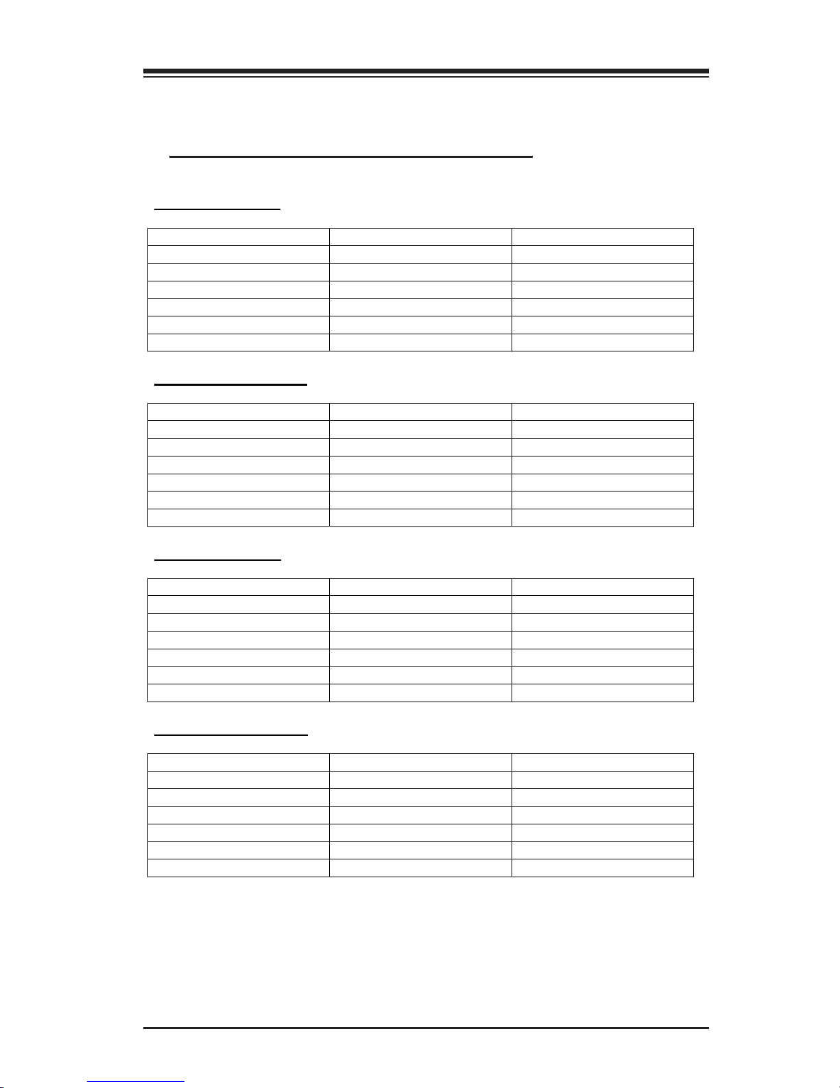
1-7. Packing List and the SC512 Specifi cations
A. The SC512 chassis contains the following:
The SC512L Series:
Component Qty Part Number
Blower One (3800rpm blower) FAN-0038
HDD Two 3.5” Drives -USB N/A -Floppy N/A -CD-ROM N/A -Power 200W PWS-0043
The SC512L-260 Series:
Component Qty Part Number
Blower One (5000rpm blower) FAN-0059
HDD Two 3.5” Drives -USB N/A -Floppy N/A -CD-ROM N/A -Power 260W PWS-0055
The SC512C Series:
Component Qty Part Number
Blower One (3800rpm blower) FAN-0038
HDD One 3.5” Drive -USB One 2.0 Connection -Floppy One Slim FDD FPD-MISMI-02
CD-ROM One Slim CD-ROM CDM-TEAC-24
Power 200W PWS-0043
The SC512C-260 Series:
Component Qty Part Number
Blower One (5000rpm blower) FAN-0059
HDD One 3.5” Drive -USB One 2.0 Connection -Floppy One Slim FDD FPD-MISMI-02
CD-ROM One Slim CD-ROM CDM-TEAC-24
Power 260W PWS-0055
1-7

SC512 Chassis User’s Guide
B. The Accessory Kit
Component Quantity
AC Power Cord 1
Screws 1 set
Rackmount Kit 1 (CSE-PT8) –(*optional)
SC512 I/O Label 2
Hard Disk Drive Mounting Kit 1
Air Shroud 1
C. Chassis Specifi cations
Specifications
Form Factor 14” mini 1U chassis support for maximum MB size:
12”x9.7” (304.7mmx 246.4mm) ATX
CPU Support Pentium 4
Expansion Card One full-height/half-length PCI Slot (w/Riser Card)
Drive Bays The SC512L Series: two 3.5” fixed, the SC512C Series:
one 3.5 fixed
Cooling System One 10cm blower (200W: 3800rpm, 260W: 5000rpm)
Front Panel LEDs One PWR LED, one HDD Activity LED, two Network
Interface LEDs, one System Overheat LED
Front Panel Buttons PowerOn/Off button, System Reset button
Dimensions 16.8”x1.7”x14.0” (427mmx43mmx356mm) (WxHxD)
Rails (Optional) Extendable 28.5” to 33.25”
Operating Temperature +10
Non Operating Temperature -40
Humidity (Operating) 8-90% (non-condensing)
Humidity (Non-Operating) 5-95% (non-condensing)
0
C to +350C (+500F to +950F)
0
C to +700C (-400F to +1580F)
D. Power Supply Specifi cations
Power supply spec 260W 200W
Mfr. Model# SP262-1S SP200-1S
Mfr. Part# PWS-0055 PWS-0038
Rated AC input voltage 100-240V AC 100-240V AC
Rated input frequency 50-60 Hz 50-60 Hz
Rated input current 5A MAX 5A MAX
Rated output power 260W 200W
Maximum rated BTU 1370 BTUs/Hr BTUs/Hr
Nominal DC output
+3.3V 15A 15A
+5V 25A 25A
+12V 18A 18A
-12V 1A 1A
+5Vsb 2A 2A
1-8
 Loading...