

Supero SC503 Series, SC503-200B User Manual
SC503 Chassis Series
SC503-200B
SUPER
®
USER’S MANUAL
1.0a
B C D E F G H I J K L M
R E V I S I O N S / -×-q
REV
ª©¥»
DESCRIPTION
±Ô-
z
LOCATION
¦ì¸m
DRAWN
-קïªÌ
DATE
¤é´Á

ii
SC503 Chassis Manual
Manual Revision 1.0a
Release Date: March 27, 2008
The information in this User’s Manual has been carefully reviewed and is believed to be accurate.
The vendor assumes no responsibility for any inaccuracies that may be contained in this document,
makes no commitment to update or to keep current the information in this manual, or to notify any
person or organization of the updates. Please Note: For the most up-to-date version of this
manual, please see our web site at www.supermicro.com.
Super Micro Computer, Inc. ("Supermicro") reserves the right to make changes to the product
described in this manual at any time and without notice. This product, including software, if any,
and documentation may not, in whole or in part, be copied, photocopied, reproduced, translated or
reduced to any medium or machine without prior written consent.
IN NO EVENT WILL SUPERMICRO BE LIABLE FOR DIRECT, INDIRECT, SPECIAL, INCIDENTAL,
SPECULATIVE OR CONSEQUENTIAL DAMAGES ARISING FROM THE USE OR INABILITY TO
USE THIS PRODUCT OR DOCUMENTATION, EVEN IF ADVISED OF THE POSSIBILITY OF
SUCH DAMAGES. IN PARTICULAR, SUPERMICRO SHALL NOT HAVE LIABILITY FOR ANY
HARDWARE, SOFTWARE, OR DATA STORED OR USED WITH THE PRODUCT, INCLUDING THE
COSTS OF REPAIRING, REPLACING, INTEGRATING, INSTALLING OR RECOVERING SUCH
HARDWARE, SOFTWARE, OR DATA.
Any disputes arising between manufacturer and customer shall be governed by the laws of Santa
Clara County in the State of California, USA. The State of California, County of Santa Clara shall
be the exclusive venue for the resolution of any such disputes. Super Micro's total liability for
all claims will not exceed the price paid for the hardware product.
FCC Statement: This equipment has been tested and found to comply with the limits for a Class
A digital device pursuant to Part 15 of the FCC Rules. These limits are designed to provide
reasonable protection against harmful interference when the equipment is operated in a commercial
environment. This equipment generates, uses, and can radiate radio frequency energy and, if not
installed and used in accordance with the manufacturer’s instruction manual, may cause harmful
interference with radio communications. Operation of this equipment in a residential area is likely
to cause harmful interference, in which case you will be required to correct the interference at your
own expense.
California Best Management Practices Regulations for Perchlorate Materials: This Perchlorate
warning applies only to products containing CR (Manganese Dioxide) Lithium coin cells. “Perchlorate
Material-special handling may apply. See www.dtsc.ca.gov/hazardouswaste/perchlorate”
WARNING: Handling of lead solder materials used in this
product may expose you to lead, a chemical known to
the State of California to cause birth defects and other
reproductive harm.
Unless you request and receive written permission from Super Micro Computer, Inc., you may not
copy any part of this document.
Information in this document is subject to change without notice. Other products and companies
referred to herein are trademarks or registered trademarks of their respective companies or mark
holders.
Copyright © 2008 by Super Micro Computer, Inc.
All rights reserved.
Printed in the United States of America

iii
Preface
Preface
About This Manual
This manual is written for professional system integrators and PC technicians. It
provides information for the installation and use of the SC503 chassis. Installation
and maintenance should be performed by experienced technicians only.
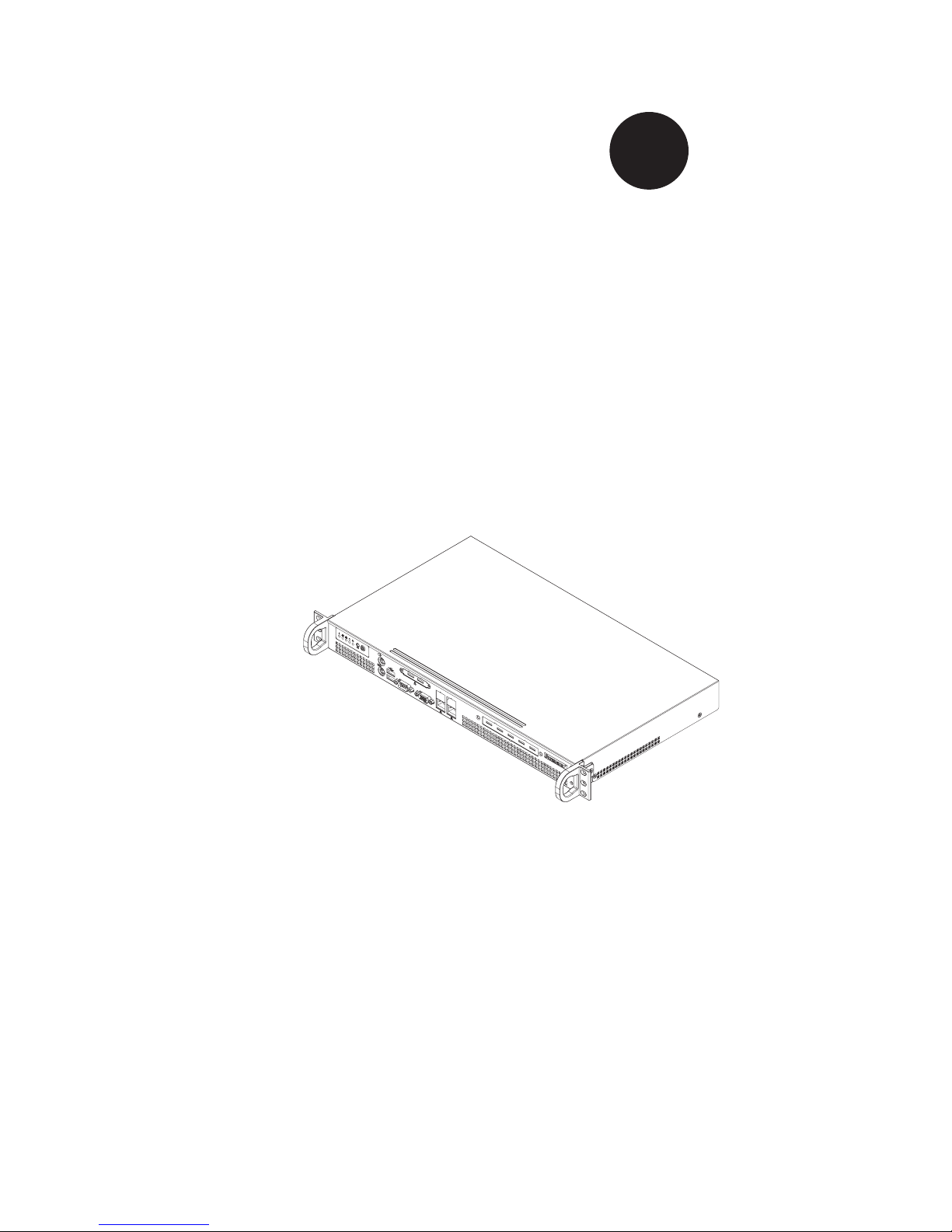
Supermicro’s SC503 chassis features a unique and highly-optimized design for low
wattage processor platforms. The chassis is equipped with a 200W high efficiency
power supply for superb power savings. High performance fans provide ample
optimized cooling.
This document lists compatible parts available when this document was published.
Always refer to the our Web site
for updates on supported parts and configura-
tions.

iv
Manual Organization
Chapter 1 Introduction
The first chapter provides a checklist of the main components included with this
chassis and describes the main features of the SC503 chassis. This chapter also
includes contact information.
Chapter 2 System Safety
This chapter lists warnings, precautions, and system safety. It recommended that
you thoroughly familiarize yourself installing and servicing this chassis safety pre-
cautions.
Chapter 3 Chassis Components
Refer here for details on this chassis model including the fans, airflow shields, and
other components.
Chapter 4 Chassis Setup and Installation
Follow the procedures given in this chapter when installing, removing, or
reconfiguring your chassis.
Chapter 5 Rack Installation
Refer to this chapter for detailed information on chassis rack installation. You should
follow the procedures given in this chapter when installing, removing or reconfiguring
your chassis into a rack environment.
Appendix A Chassis Hardware
Appendix B: Power Supply Specifications
SC503 Chassis Manual

v
Preface
Table of Contents
Chapter 1 Introduction
1-1 Overview ......................................................................................................... 1-1
1-2 Shipping List .................................................................................................... 1-
1
Part Numbers .................................................................................................. 1-
1
1-3 Where to get Replacement Components ........................................................ 1-2
1-4 Contacting Supermicro .................................................................................... 1-
3
1-5 Returning Merchandise for Service ................................................................ 1-
4
Chapter 2 System Safety
2-1 Overview ......................................................................................................... 2-1
2-2 Warnings and Precautions .............................................................................. 2-
1
2-3 Preparing for Setup ......................................................................................... 2-1
2-4 Electrical Safety Precautions .......................................................................... 2-2
2-5 General Safety Precautions ............................................................................ 2-3
2-6 System Safety ................................................................................................. 2-3
Chapter 3 Chassis Components
3-1 Overview ......................................................................................................... 3-1
3-2 Components .................................................................................................... 3-1
Chassis ............................................................................................................ 3-
1
Mounting to a Rack (optional
) ......................................................................... 3-1
Power Supply .................................................................................................. 3-1
3-3 Where to get Replacement Components ........................................................ 3-2
Chapter 4 Chassis Setup and Maintenance
4-1 Overview ......................................................................................................... 4-1
4-2 Removing the Chassis Cover ......................................................................... 4-2
4-3 Installing the Hard Drives ................................................................................ 4-3
4-4 Installing the Motherboard .............................................................................. 4-4
Chassis
Standoffs ........................................................................................... 4-4
Motherboard Installation .................................................................................. 4-
5
Add-on Card/Expansion
Slot Setup ................................................................ 4-6
4-5 Replacing the Heatsink ................................................................................... 4-7
Checking the Server's Air
Flow ....................................................................... 4-8
4-8 Power Supply ................................................................................................. 4-9
Replacing the Power Supply ........................................................................... 4-
9
Chapter 5 Rack Installation
5-1 Overview ......................................................................................................... 5-1
5-2 Unpacking the System .................................................................................... 5-1

vi
5-3 Preparing for Setup ......................................................................................... 5-1
Choosing a Setup Location ............................................................................. 5-
1
Rack Precautions ............................................................................................ 5-
2
General Server Precautions ............................................................................ 5-
2
Rack Mounting Considerations ....................................................................... 5-
3
Ambient Operating Temperature ................................................................ 5-
3
Reduced Airflow ......................................................................................... 5-
3
Mechanical Loading ................................................................................... 5-
3
Circuit Overloading ..................................................................................... 5-
3
5-4 Rack Mounting Instructions ............................................................................. 5-4
Installing the Chassis into a Rack: ................................................................. 5-
4
Installing the Chassis into a Telco Rack: ........................................................ 5-
5
Appendix A Cables, Screws, and other Accessories
Appendix
B SC503 Power Supply Specifications
Chapter 1
Introduction
1-1 Overview
Supermicro’s SC503 chassis features a unique and highly-optimized design. The
chassis is equipped with high efficiency 80%+ low noise power supply.
1-2 Shipping List
Part Numbers
Please visit the following link for the latest shiping lists and part numbers for your
particular chassis model http://www.supermicro.com/
Chapter 1: Introduction
1-1
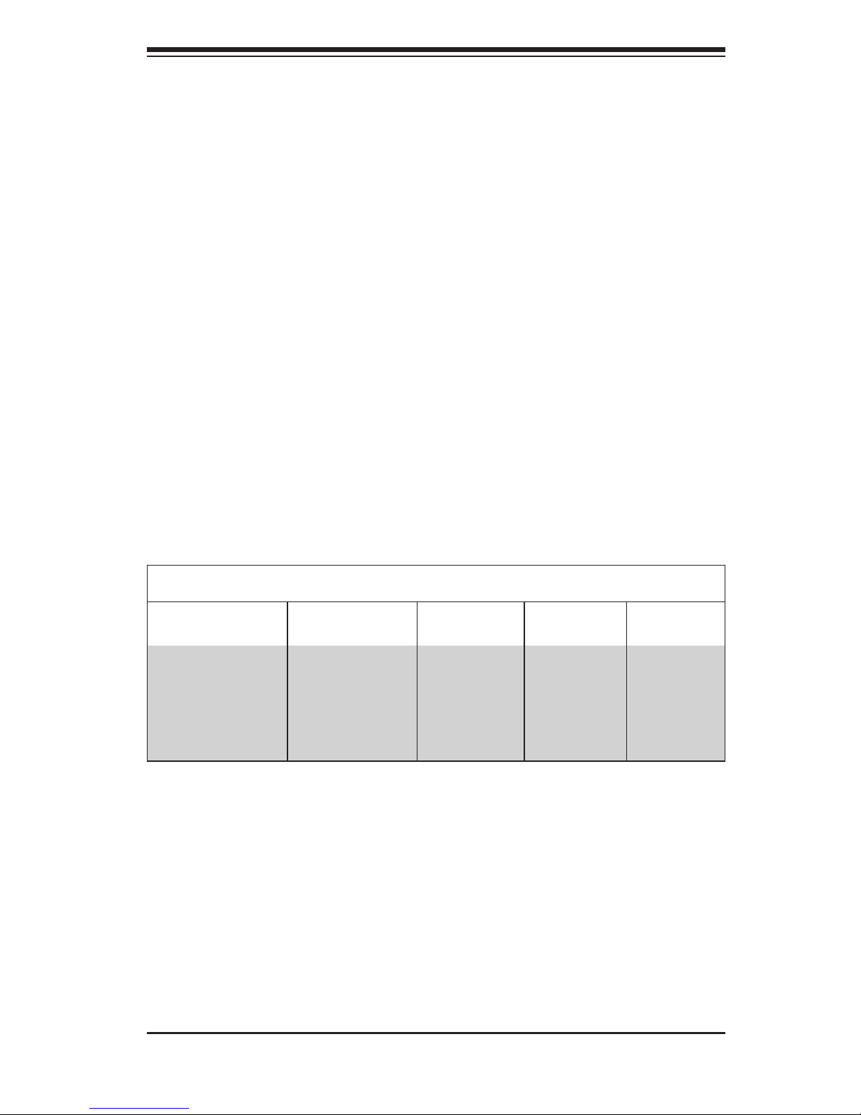
SC503-200B Chassis
Model CPU HDD I/O Slots
Power
Supply
SC503-200(B)
Intel Celeron
400 series (35W)
or low power
platforms under
20W.
(See below)
1 Fixed 3.5"
hard drive or
up to 2 fixed
2.5" hard
drives
1x FH
(optional)
200W
IMPORTANT: It is critical to choose the correct heatsink for your motherboard, that
will fit in the SC503 chassis.
Intel Celeron 400 seriew (35W) platform: Active heatsink SNKP0032A4
Low power platforms under 20W: Passive heatsink SNKP0016P
1.
2.

SC503 Chassis Manual
1-2
1-3 Where to get Replacement Components
Though not frequently, you may need replacement parts for your system. To en-
sure the highest level of professional service and technical support, we strongly
recommend purchasing exclusively from our Supermicro Authorized Distributors /
System Integrators / Resellers. A list of Supermicro Authorized Distributors / System
Integrators /Reseller can be found at: http://www.supermicro.com. Click the Where
to Buy link.

1-3
Chapter 1: Introduction
1-4 Contacting Supermicro
Headquarters
Address: Super Micro Computer, Inc.
980 Rock Ave.
San Jose, CA 95131 U.S.A.
Tel: +1 (408) 503-8000
Fax: +1 (408) 503-8008
Email: marketing@supermicro.com (General Information)
support@supermicro.com (Technical Support)
Web Site: www.supermicro.com
Europe
Address: Super Micro Computer B.V.
Het Sterrenbeeld 28, 5215 ML
's-Hertogenbosch, The Netherlands
Tel: +31 (0) 73-6400390
Fax: +31 (0) 73-6416525
Email: sales@supermicro.nl (General Information)
support@supermicro.nl (Technical Support)
rma@supermicro.nl (Customer Support)
Asia-Pacific
Address: Super Micro Computer, Inc.
4F, No. 232-1, Liancheng Rd.
Chung-Ho 235, Taipei County
Taiwan, R.O.C.
Tel: +886-(2) 8226-3990
Fax: +886-(2) 8226-3991
Web Site: www.supermicro.com.tw
Technical Support:
Email: support@supermicro.com.tw
Tel: 886-2-8226-1900

SC503 Chassis Manual
1-4
1-5 Returning Merchandise for Service
A receipt or copy of your invoice marked with the date of purchase is required be-
fore any warranty service will be rendered. You can obtain service by calling your
vendor for a Returned Merchandise Authorization (RMA) number. When returning
to the manufacturer, the RMA number should be prominently displayed on the
outside of the shipping carton, and mailed prepaid or hand-carried. Shipping and
handling charges will be applied for all orders that must be mailed when service
is complete.
For faster service, RMA authorizations may be requested online (http://www.
supermicro.com/support/rma/).
Whenever possible, repack the chassis in the original Supermicro carton, using the
original packaging material. If these are no longer available, be sure to pack the
chassis securely, using packaging material to surround the chassis so that it does
not shift within the carton and become damaged during shipping.
This warranty only covers normal consumer use and does not cover damages in
-
curred in shipping or from failure due to the alteration, misuse, abuse or improper
maintenance of products.
During the warranty period, contact your distributor first for any product problems.

2-1
Chapter 2: System Safety
Chapter 2
System Safety
2-1 Overview
This chapter provides a quick setup checklist to get your chassis up and running.
Following the steps in order given should enable you to have your chassis setup and
operational within a minimal amount of time. This quick set up assumes that you
are an experienced technician, famailiar with common concepts and terminology.
2-2 Warnings and Precautions
You should inspect the box the chassis was shipped in and note if it was damaged
in any way. If the chassis itself shows damage, file a damage claim with carrier
who delivered your system.
Decide on a suitable location for the rack unit that will hold that chassis. It should
be situated in a clean, dust-free area that is well venilated. Avoid areas where heat,
electrical noise and eletromagnetic fields are generated.
You will also need it placed near at least one grounded power outlet. When config
-
ured, the SC503 chassis includes one power supply.
2-3 Preparing for Setup
The SC503 Chassis bolts directly to a rack and includes the mounting screws you
will need to install the systems into the rack. Please read this manual in its entirety
before you begin the installation procedure.

SC503 Chassis Manual
2-2
2-4 Electrical Safety Precautions
Basic electrical safety precautions should be followed to protect yourself from harm
and the SC503 from damage:
Be aware of the locations of the power on/off switch on the chassis as well
as the room’s emergency power-off switch, disconnection switch or electrical
outlet. If an electrical accident occurs, you can then quickly remove power from
the system.
Do not work alone when working with high voltage components.
Power should always be disconnected from the system when removing or in
-
stalling main system components, such as the serverboard, memory modules
and the DVD-ROM and floppy drives (not necessary for hot swappable drives).
When disconnecting power, you should first power down the system with the
operating system and then unplug the power cords from all the power supply
modules in the system.
When working around exposed electrical circuits, another person who is fa
-
miliar with the power-off controls should be nearby to switch off the power, if
necessary.
Use only one hand when working with powered-on electrical equipment. This
is to avoid making a complete circuit, which will cause electrical shock. Use
extreme caution when using metal tools, which can easily damage any electrical
components or circuit boards they come into contact with.
Do not use mats designed to decrease electrostatic discharge as protection from
electrical shock. Instead, use rubber mats that have been specifically designed
as electrical insulators.
The power supply power cord must include a grounding plug and must be
plugged into grounded electrical outlets.
Serverboard Battery: CAUTION - There is a danger of explosion if the onboard
battery is installed upside down, which will reverse its polarities This battery
must be replaced only with the same or an equivalent type recommended by
the manufacturer. Dispose of used batteries according to the manufacturer’s
instructions.
•
•
•
•
•
•
•
•
 Loading...