

Page 1
SUPER
®
MH2
C202
C198
+
C197
+
C201
+
MH4
C152
SAS837A
REV 1.00
DESIGNED IN USA
PRI:#8-#11
A1B1A18
PRI_J2
SEC:#8-#11
A1B1A18
SEC_J2
4
B18
JP5:
1
OPEN: DEFAULT
CLOSE: ACT LED TEST
JP5
JP6:
OPEN: DEFAULT
B18
CLOSE: FAIL LED TEST
JP6
1
JP46
1
MH10 MH1
C285
C119
+
MH9
C84
+
C111
D65
C85
+
MH8
C76
C81
PRI:#4-#7
A1B1A18
SEC:#4-#7
A1B1A18
4
JP4:I2C
JP4
PRI_J1
SEC_J1
BAR CODE
PRI:#0-#3
A1B1A18
PRI_J0
SEC:#0-#3
A1B1A18
SEC_J0
MH7
B18
B18
JP10
1
MH3
D53
C5
+
U24
B18
U1
B18
JP13
1
C45
+
C58
MH6
C44
+
C3
U18
+
MH5
D54
A C
C
A
4
SAS-837A BACKPLANE
USER'S GUIDE
Rev. 1.0
Page 2

SAS-837A Backplane User's Guide
The information in this User’s Manual has been carefully reviewed and is believed to be accurate.
The vendor assumes no responsibility for any inaccuracies that may be contained in this document,
makes no commitment to update or to keep current the information in this manual, or to notify any
person or organization of the updates. Please Note: For the most up-to-date version of this
manual, please see our web site at www.supermicro.com.
Super Micro Computer, Inc. ("Supermicro") reserves the right to make changes to the product
described in this manual at any time and without notice. This product, including software and
documentation, is the property of Supermicro and/or its licensors, and is supplied only under a
license. Any use or reproduction of this product is not allowed, except as expressly permitted by
the terms of said license.
IN NO EVENT WILL SUPERMICRO BE LIABLE FOR DIRECT, INDIRECT, SPECIAL, INCIDENT AL,
SPECULATIVE OR CONSEQUENTIAL DAMAGES ARISING FROM THE USE OR INABILITY TO
USE THIS PRODUCT OR DOCUMENTATION, EVEN IF ADVISED OF THE POSSIBILITY OF
SUCH DAMAGES. IN PARTICULAR, SUPERMICRO SHALL NOT HAVE LIABILITY FOR ANY
HARDWARE, SOFTW ARE, OR DA TA STORED OR USED WITH THE PRODUCT, INCLUDING THE
COSTS OF REPAIRING, REPLACING, INTEGRATING, INSTALLING OR RECOVERING SUCH
HARDWARE, SOFTWARE, OR DATA.
Any disputes arising between manufacturer and customer shall be governed by the laws of Santa
Clara County in the State of California, USA. The State of California, County of Santa Clara shall
be the exclusive venue for the resolution of any such disputes. Super Micro's total liability for all
claims will not exceed the price paid for the hardware product.
California Best Management Practices Regulations for Perchlorate Materials: This Perchlorate
warning applies only to products containing CR (Manganese Dioxide) Lithium coin cells. “Perchlorate
Material-special handling may apply. See www.dtsc.ca.gov/hazardouswaste/perchlorate”
WARNING: Handling of lead solder materials used in this
product may expose you to lead, a chemical known to
the State of California to cause birth defects and other
reproductive harm.
Manual Revision 1.0
Release Date: January 26, 2011
Unless you request and receive written permission from Super Micro Computer, Inc., you may not
copy any part of this document.
Information in this document is subject to change without notice. Other products and companies
referred to herein are trademarks or registered trademarks of their respective companies or mark
holders.
Copyright © 2011 by Super Micro Computer, Inc.
All rights reserved.
Printed in the United States of America
ii
Page 3

Safety Information and Technical Specifi cations
Table of Contents
Contacting Supermicro .......................................................................................iv
Returning Merchandise for Service.....................................................................v
Chapter 1 Safety Guidelines
1-1 ESD Safety Guidelines ................................................................................... 1-1
1-2 General Safety Guidelines .............................................................................. 1-1
1-3 An Important Note to Users ............................................................................ 1-2
1-4 Introduction to the SAS-837A Backplane ........................................................1-2
Chapter 2 Connectors, Jumpers and LEDs
2-1 Front Connectors ............................................................................................2-1
2-2 Front Connector and Pin Defi nitions ............................................................... 2-2
2-3 Front LED Indicators ....................................................................................... 2-3
2-4 Rear Connectors and LED Indicators .............................................................2-4
Chapter 3 Connecting the SAS2-837A and SAS-837EL Backplanes
3-1 Connecting Dual Backplanes ..........................................................................3-1
Identifying the Backplanes .............................................................................. 3-1
Confi guring Dual Backplanes ..........................................................................3-2
iii
Page 4

SAS-837A Backplane User's Guide
Contacting Supermicro
Headquarters
Address: Super Micro Computer, Inc.
980 Rock Ave.
San Jose, CA 95131 U.S.A.
Tel: +1 (408) 503-8000
Fax: +1 (408) 503-8008
Email: marketing@supermicro.com (General Information)
support@supermicro.com (Technical Support)
Web Site: www.supermicro.com
Europe
Address: Super Micro Computer B.V.
Het Sterrenbeeld 28, 5215 ML
's-Hertogenbosch, The Netherlands
Tel: +31 (0) 73-6400390
Fax: +31 (0) 73-6416525
Email: sales@supermicro.nl (General Information)
support@supermicro.nl (Technical Support)
rma@supermicro.nl (Customer Support)
Asia-Pacifi c
Address: Super Micro Computer, Inc.
4F, No. 232-1, Liancheng Rd.
Chung-Ho 235, Taipei County
Taiwan, R.O.C.
Tel: +886-(2) 8226-3990
Fax: +886-(2) 8226-3991
Web Site: www.supermicro.com.tw
Technical Support:
Email: support@supermicro.com.tw
Tel: 886-2-8226-1900
iv
Page 5

Safety Information and Technical Specifi cations
Returning Merchandise for Service
A receipt or copy of your invoice marked with the date of purchase is required before any warranty service will be rendered. You can obtain service by calling your
vendor for a Returned Merchandise Authorization (RMA) number. When returning
to the manufacturer, the RMA number should be prominently displayed on the
outside of the shipping carton, and mailed prepaid or hand-carried. Shipping and
handling charges will be applied for all orders that must be mailed when service
is complete.
For faster service, RMA authorizations may be requested online (http://www.
supermicro.com/support/rma/).
Whenever possible, repack the backplane in the original Supermicro box, using the
original packaging materials. If these are no longer available, be sure to pack the
backplane in an anti-static bag and inside the box. Make sure that there is enough
packaging material surrounding the backplane so that it does not become damaged
during shipping.
This warranty only covers normal consumer use and does not cover damages incurred in shipping or from failure due to the alteration, misuse, abuse or improper
maintenance of products.
During the warranty period, contact your distributor fi rst for any product problems.
v
Page 6

SAS-837A Backplane User's Guide
Notes
vi
Page 7

Safety Information and Technical Specifi cations
Chapter 1
Safety Guidelines
To avoid personal injury and property damage, carefully follow all the safety steps
listed below when accessing your system or handling the components.
1-1 ESD Safety Guidelines
Electrostatic Discharge (ESD) can damage electronic com ponents. To prevent damage to your system, it is important to handle it very carefully . The following measures
are generally suffi cient to protect your equipment from ESD.
Use a grounded wrist strap designed to prevent static discharge.
•
Touch a grounded metal object before removing a component from the antistatic •
bag.
Handle the backplane by its edges only; do not touch its components, peripheral
•
chips, memory modules or gold contacts.
When handling chips or modules, avoid touching their pins.
•
Put the backplane and peripherals back into their antistatic bags when not in •
use.
1-2 General Safety Guidelines
Always disconnect power cables before installing or removing any components •
from the computer, including the backplane.
Disconnect the power cable before installing or removing any cables from the
•
backplane.
Make sure that the backplane is securely and properly installed on the mother-
•
board to prevent damage to the system due to power shortage.
1-1
Page 8

SAS-837A Backplane User's Guide
1-3 An Important Note to Users
All images and layouts shown in this user's guide are based upon the latest PCB
revision available at the time of publishing. The card you have received may or may
not look exactly the same as the graphics shown in this manual.
1-4 Introduction to the SAS-837A Backplane
The SAS-837A backplane has been designed to utilize the most up-to-date technology available, providing your system with reliable, high-quality performance.
This manual refl ects SAS-837A Revision 1.00, the most current release available at
the time of publication. Always refer to the Supermicro W eb site at www.supermicro.
com for the latest updates, compatible parts and supported confi gurations.
1-2
Page 9

Connectors, Jumpers and LEDs
2-1 Front Connectors
MH2
C202
C198
+
C197
+
C201
+
MH4
C152
SAS837A
5
1
REV 1.00
DESIGNED IN USA
PRI:#8-#11
A1B1A18
PRI_J2
8
1
SEC:#8-#11
A1B1A18
SEC_J2
4
B18
JP5:
1
OPEN: DEFAULT
CLOSE: ACT LED TEST
JP5
MH9
JP6:
OPEN: DEFAULT
B18
CLOSE: FAIL LED TEST
JP6
1
JP46
1
C85
MH8
Safety Information and Technical Specifi cations
Chapter 2
1
PRI:#4-#7
A1B1A18
SEC:#4-#7
A1B1A18
4
1
JP4:I2C
JP4
B18
PRI_J1
7
1
B18
SEC_J1
JP13
1
C5
+
U24
U1
C45
+
C58
MH6
C44
+
C3
U18
+
MH5
D53
D54
A C
C
A
4
MH10 MH1
C285
C119
+
C84
+
+
4
1
C111
D65
C76
C81
3
1
BAR CODE
PRI:#0-#3
A1B1A18
PRI_J0
6
1
SEC:#0-#3
A1B1A18
SEC_J0
MH7
B18
B18
JP10
1
MH3
2
1
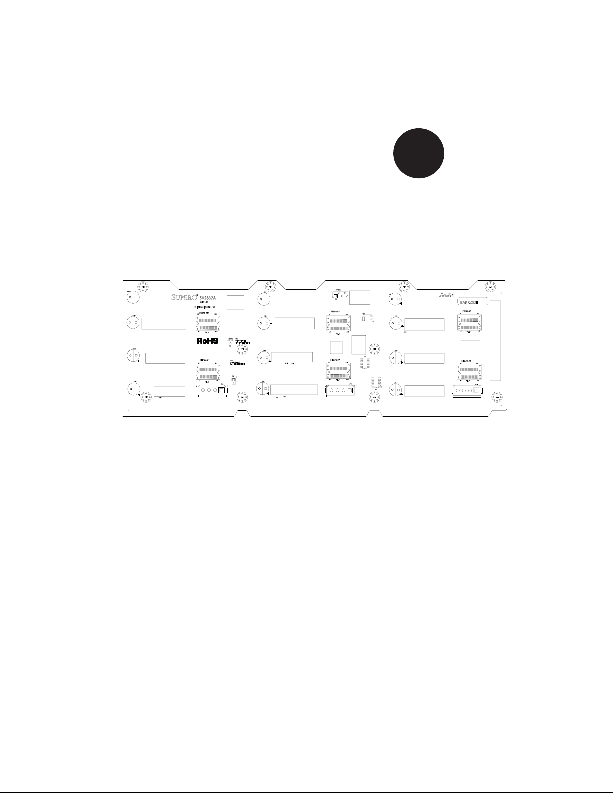
Figure 2-1: Front Connectors
Front Connectors
I1. 2C connector: JP4:I2C
Power connectors: JP46, JP13 and 2.
JP10.
Primary SAS port: PRI_J03.
Primary SAS port: PRI_J14.
2
1
2
1
Primary SAS port: PRI_J25.
Secondary SAS port: SEC_J06.
Secondary SAS port SEC_J17.
Secondary SAS port SEC_J28.
2-1
Page 10
SAS-837A Backplane User's Guide
2-2 Front Connector and Pin Defi nitions
1. I2C Connector
2
C connector is used to monitor the power
The I
supply status and to control the fans. See the
table on the right for pin defi nitions.
2. Backplane Main Power Connectors
The 4-pin connectors, designated JP46,
JP13 and JP10 provide power to the backplane. See the table on the right for pin
defi nitions.
I2C Connector
Pin Defi nitions
Pin# Defi nition
1 Data
2 Ground
3 Clock
4 No Connection
Backplane
Main Power
4-Pin Connector
Pin# Defi nition
1
2 and 3 Ground
4 +5V
+12V
3. - 8. SAS Ports
The primary and secondary sets of SAS
ports provide expander features including
cascading and failover. From right to left the
ports are Primary 0 through Primary 2 and
Secondary 0 through Secondary 2.
2-2
Page 11

2-3 Front LED Indicators
Safety Information and Technical Specifi cations
MH2
C202
C198
+
C197
+
C201
+
MH4
C152
SAS837A
REV 1.00
DESIGNED IN USA
PRI:#8-#11
A1B1A18
PRI_J2
SEC:#8-#11
A1B1A18
SEC_J2
4
B18
JP5:
1
OPEN: DEFAULT
CLOSE: ACT LED TEST
JP5
JP6:
OPEN: DEFAULT
B18
CLOSE: FAIL LED TEST
JP6
1
JP46
1
MH10 MH1
C285
C119
+
MH9
C84
+
C111
D65
C85
+
MH8
C76
C81
PRI:#4-#7
A1B1A18
SEC:#4-#7
A1B1A18
4
JP4:I2C
JP4
PRI_J1
SEC_J1
C5
+
U24
B18
MH6
U1
B18
JP13
1
U18
MH5
5V_LED
C45
+
C58
C44
+
C3
+
12V_LED
D53
D54
A C
C
A
BAR CODE
PRI:#0-#3
B18
A1B1A18
PRI_J0
SEC:#0-#3
B18
A1B1A18
SEC_J0
JP10
4
MH7
1
MH3
Figure 2-2: Front LED Indicators
Front LEDs
LED
Default
State
5V_LED1 On
12V_LED2 On
Specifi cation
Green LED indicates backplane power activity. Light is on during normal operation
Green LED indicates backplane power activity. Light is on during normal operation.
2-3
Page 12
SAS-837A Backplane User's Guide
2-4 Rear Connectors and LED Indicators
SAS #3
SAS #2
SAS #1
SAS #0
D15
C
A
C
D8
FAIL#3ACT#3
J4
SAS
#3
J3
SAS
#2
J2
SAS
#1
J1
SAS
#0
A
D14
C
ACT#2
A
C
FAIL#2 ACT#1
A
D7
D13
C
A
C
FAIL#1 ACT#0 FAIL#0
A
D6
D12
R83
C
A
C
A
D5
SAS #4
SAS #7
SAS #6
SAS #5
J15
SAS
#7
J13
SAS
#6
J11
SAS
#5
J9
SAS
#4
D24
C
C
A
D29
FAIL#7
A
SAS #11
D22
C
ACT#6ACT#7
A
C
FAIL#6
A
D23
SAS #10
D21
C
ACT#5
A
C
FAIL#5
A
D20
SAS #9
D18
C
A
C
FAIL#4
A
D19
SAS #8
J20
SAS
#11
J19
SAS
#10
J18
SAS
#9
J17
SAS
#8
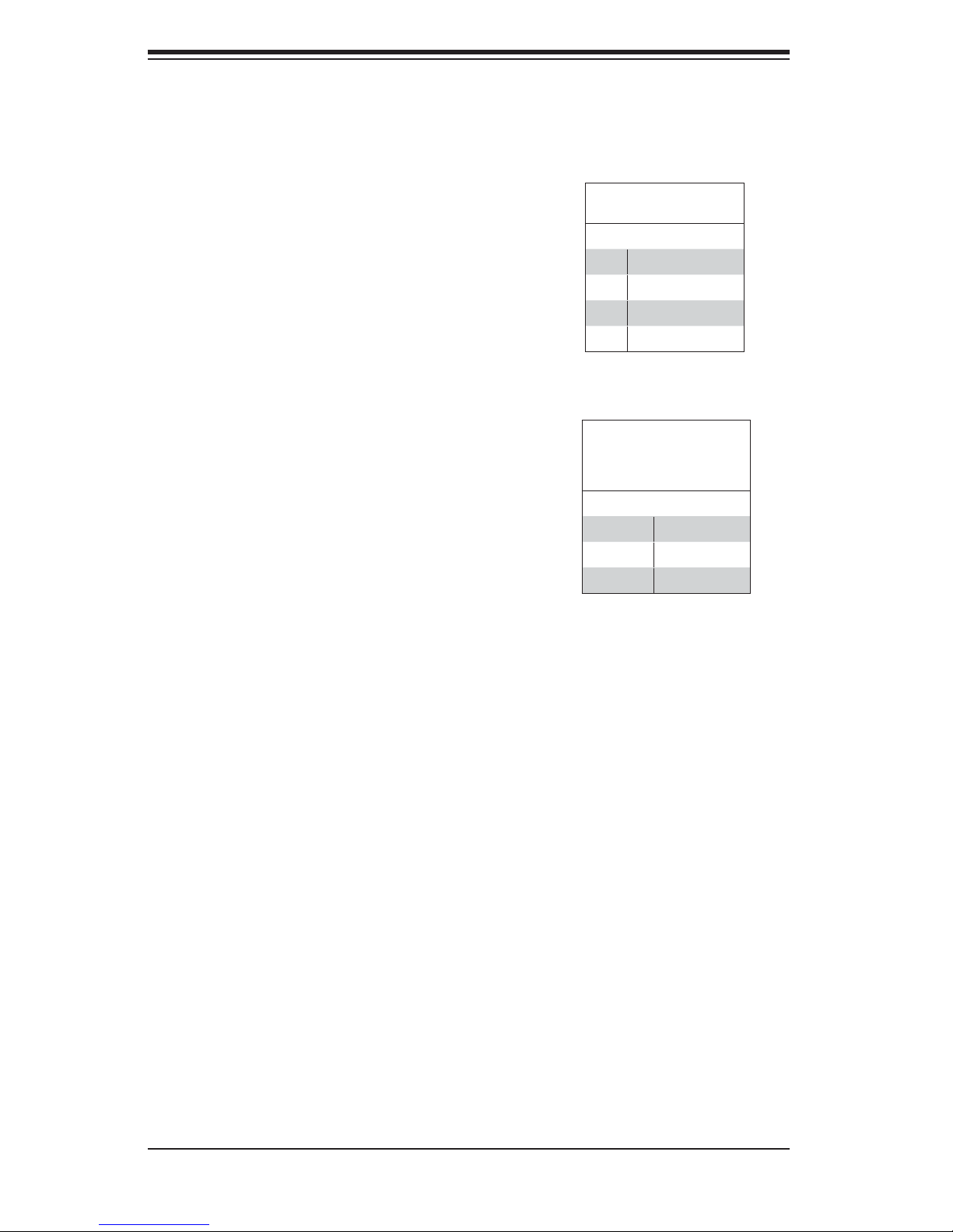
Figure 2-3: Rear Connectors
Rear SAS/SATA Connectors
Rear
Connector
SAS Drive
Number
Rear
Connector
SAS Drive
Number
SAS #0 SAS/SATA HDD #0 SAS #6 SAS/SATA HDD #6
SAS #1 SAS/SATA HDD #1 SAS #7 SAS/SATA HDD #7
D28
C
A
C
FAIL#11ACT#11
A
D33
D27
C
ACT#10
A
C
FAIL#10
A
D32
D26
ACT#9
C
A
C
FAIL#9
A
D31
D25
C
A
C
FAIL#8ACT#8
A
D30
SAS #2 SAS/SATA HDD #2 SAS #8 SAS/SATA HDD #8
SAS #3 SAS/SATA HDD #3 SAS #9 SAS/SATA HDD #9
SAS #4
SAS/SATA HDD #4
SAS #10
SAS/SATA HDD #10
SAS #5 SAS/SATA HDD #5 SAS #11 SAS/SATA HDD #11
Rear LED Indicators
Rear
Connector
Hard Drive
Activity LED
Failure
LED
Rear
Connector
Hard Drive Ac-
tivity LED
Failure
LED
SAS #0 ACT #0 FAIL #0 SAS #6 ACT #6 FAIL #6
SAS #1 ACT #1 FAIL #1 SAS #7 ACT #7 FAIL #7
SAS #2 ACT #2 FAIL #2 SAS #8 ACT #8 FAIL #8
SAS #3 ACT #3 FAIL #3 SAS #9 ACT #9 FAIL #9
SAS #4 ACT #4 FAIL #4 SAS #10 ACT #10 FAIL #10
SAS #5 ACT #5 FAIL #5 SAS #11 ACT #11 FAIL #11
2-4
Page 13
Safety Information and Technical Specifi cations
Chapter 3
Connecting the
SAS2-837A and SAS-837EL Backplanes
3-1 Connecting Dual Backplanes
The SAS2-837EL and SAS-837A backplanes are designed to work together. The
following confi gurations show how the SAS2-837EL and SAS-837A may be con-
nected together.
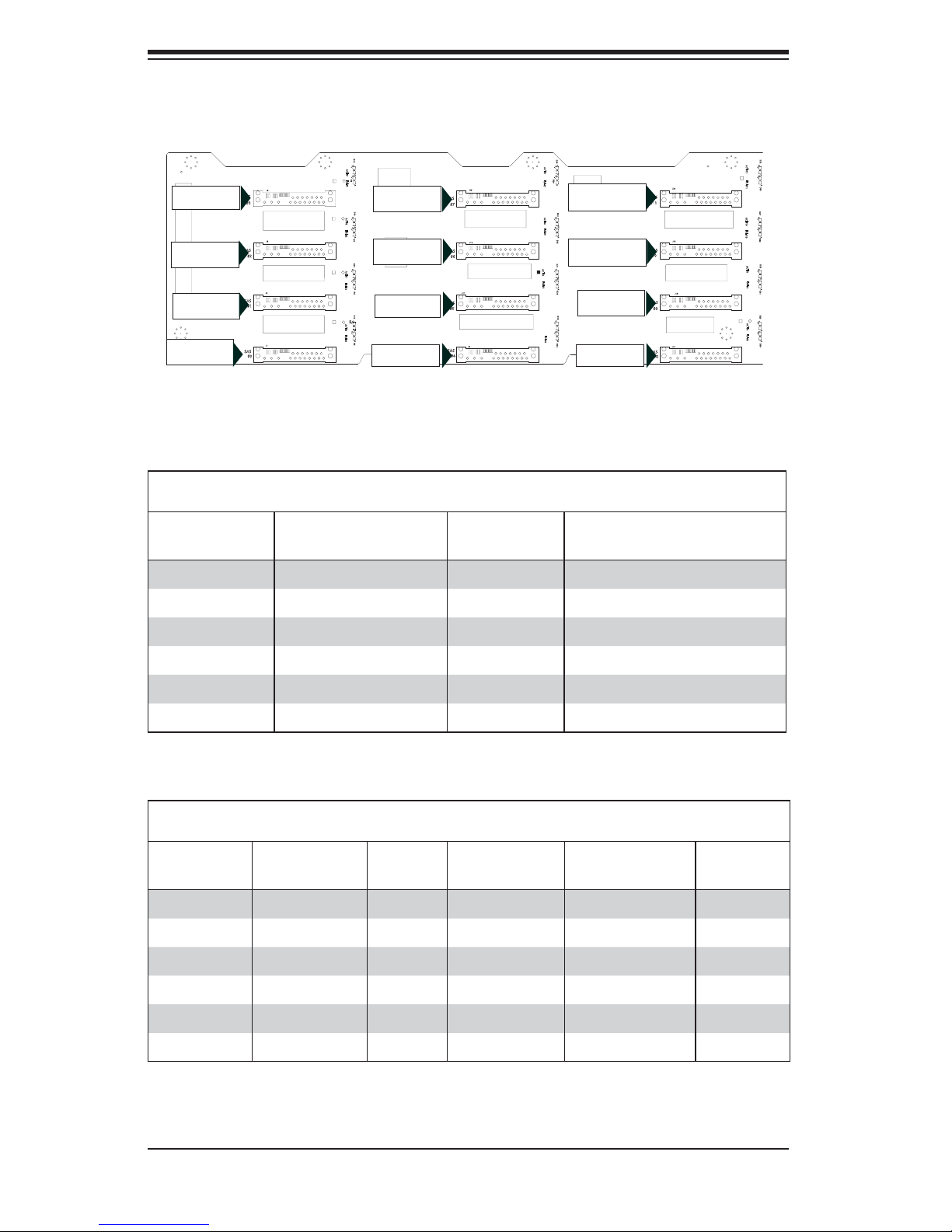
Identifying the Backplanes
Examine the diagrams below and identify the SAS2-837EL and SAS-837A backplanes. Identify the locations of the SAS ports on each board. Also note the location
of the primary I
2
C connectors, if the optional I2C confi guration is desired.
EC28
MH12
+
BC52
+
EC22
12V_LED
A
C
5V_LED
A
C
+
BPN-SAS2-837EL2
EC25
PRI_J3
BC92
BC91
PWR4
+
EC15
MH11
C202
C198
+
C197
+
C201
+
U16
+5V+12V GNDGND
MH2
MH4
PRI_J4
J24
PRI_J4
B1 B18
C2988
PRI_I2C
PRI_I2C1
PRI_J3
B1 B18
REV: 1.00
PRI_J2
B18
B1
A18
C430
L147
L148
FAN1
PRI_J2
PRI_J2
C152
SEC_J2
MH9
PRI_J0
ACT24
A
BCA534
+
EC17
C
PRI_FLASH
+
EC27
MH3
PRI_I2C1
U6
1
ACTLED1
EC16
+
+
+
+
L1
EC18
C868
+
+
EC13
MH1
Q1 Q2
Figure 3-1: SAS2-837EL Backplane
SAS837A
REV 1.00
DESIGNED IN USA
PRI:#8-#11
B18
A1B1A18
PRI_J2
1
JP5
SEC:#8-#11
A1B1A18
4
JP6:
OPEN: DEFAULT
B18
CLOSE: FAIL LED TEST
1
SEC_J2
JP46
1
WWN
EC26
+
+
C861
C866
+
PRI_J0
B1
B18
A1
A18
PRI_J1
B1 B18
+
PWR3
+12V
GND
+5V
GND
PRI_J1
C285
C119
JP5:
OPEN: DEFAULT
CLOSE: ACT LED TEST
MH9
C84
JP6
C85
MH8
+
SEC_J2
C862
MH6
BCA420
Y
K
L398
Y20K
C863
SEC_J1
E20R
5
+
10 15
+
25 28
+
C2972
MH2
+
C2973
+
C377
C867
+
C871
+
C2970
+
C2971
+
MH4
SEC_J0
EC9
+
EC8
AE
AH
C870
Y10
28
25
U4
15
10
5
+
C865
+
+
EC10
+
+
EC35
C864
L153
EC20
+
A1
Q3
+
A1
A1B1A18
UART_P
SEC_J0
EXPDBG1
B18
PWR2
+12V
+5V
GND
GND
+
B1B18
SEC_J2
L149
A18
A1
MH5
SEC_J3
B18
+
EC19
B1
1
4
EXPDBG2
1
4
UART_S
4
1
4
1
+
SEC_J4
B1B18
1
FAN2
SEC_J4
MH10 MH1
PRI_J1
PRI:#4-#7
+
A1B1A18
A1B1A18
4
SEC:#4-#7
+
C111
D65
+
C76
C81
JP4:I2C
JP4
PRI_J1
SEC_J1
JP4:I2C
U24
B18
B18
JP13
1
C5
C45
MH6
U1
C44
C3
U18
MH5
SEC_J1
L152
L151
MH8
+
U1
EC36
+
EC3
FAN_MONITOR_DISABLE
FANFAIL_LED_DISABLE
OVERHEATFAIL1
+
1
1
A C
A
FANFAIL1
C
SEC_J3
EC2
+
PWR1
GND
+5V+12V
GND
EC1
+
+
C58
+
+
+
EC4
WWN
1
8
J25
BAR CODE
U5
FAN3
1
PRI_J0
D53
D54
A C
C
A
BAR CODE
PRI:#0-#3
A1B1A18
PRI_J0
SEC:#0-#3
A1B1A18
SEC_J0
4
SEC_J0
MH13
AC
ACT25
16
17
33
U17
MH7
U332
DESIGNED IN USA
SEC_FLASH
U312
RA611
4
MH10
MH7
B18
B18
JP10
1
MH3
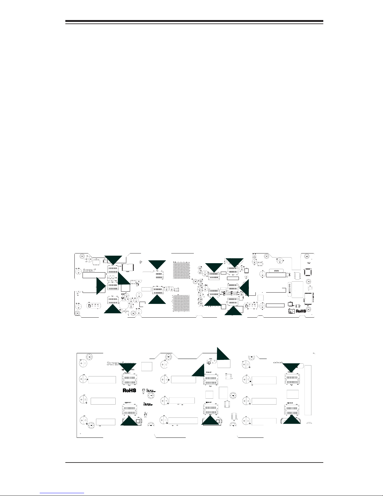
Figure 3-2: SAS-837A Backplane
3-1
Page 14

SAS-837A Backplane User's Guide
Confi guring Dual Backplanes
Confi gure the SAS2-837EL2 and SAS-837A as shown in the chart below. Connect
the port in Column A to the port in the Column B using the cable in Column C.
Dual Backplane Confi guration Chart
Column A
SAS2-837EL Port
Column B
SAS-837A Port
Column C
Cable Name
Primary SAS port PRI_J2 Primary SAS port PRI_J0 CBL-0421L
Primary SAS port PRI_J3 Primary SAS port PRI_J1 CBL-0421L
Primary SAS port PRI_J4 Primary SAS port PRI_J2 CBL-0421L
Secondary SAS port SEC_J2 Secondary SAS prot SEC_J0 CBL-0421L
Secondary SAS port SEC_J3 Secondary SAS prot SEC_J1 CBL-0421L
Secondary SAS port SEC_J4 Secondary SAS prot SEC_J2 CBL-0421L
PRI_J4
U16
J24
B1 B18
C2988
B1 B18
REV: 1.00
B1
+5V+12V GNDGND
FAN1
PRI_J2
2
C connector
PRI_J4
BCA534
PRI_I2C1
PRI_I2C
PRI_I2C1
PRI_J3
PRI_J2
B18
A18
+
C430
L147
L148
EC17
C
PRI_FLASH
+
EC27
MH3
U6
1
ACTLED1
EC16
+
+
+
+
L1
EC18
C868
+
+
EC13
MH1
Q1 Q2
EC26
MH9
+
+
PRI_J0
ACT24
A
PRI_J0
B1
A1
PRI_J1
B1 B18
PWR3
+12V
GND
PRI_J1
12C connector
JP4:I2C (optional) CBL-0102L
L152
L153
EC20
+
A1
+
B1B18
A1
MH5
SEC_J3
+
EC19
B1
EXPDBG2
4
UART_S
4
+
B1B18
L151
+
U1
EC36
Q3
+
EC3
L149
FAN_MONITOR_DISABLE
FANFAIL_LED_DISABLE
OVERHEATFAIL1
+
1
1
A C
A
FANFAIL1
C
SEC_J3
EC2
+
PWR1
GND
+5V+12V
GND
EC1
MH8
+
EC4
WWN
U17
1
8
J25
BAR CODE
U5
FAN3
4
1
WWN
C861
C866
+
AE
AH
Y
K
B18
A18
+
C870
Y10
L398
28
25
U4
15
+5V
GND
10
5
Y20K
C865
+
C863
SEC_J1
E20R
5
+
10 15
+
25 28
+
C2972
MH2
+
C2973
+
C377
C867
+
+
C2970
+
C2971
+
MH4
SEC_J0
MH6
+
+
C871
C862
+
EC9
EC8
SEC_J0
B18
PWR2
+12V
BCA420
EC10
+
A1
A1B1A18
UART_P
EXPDBG1
+5V
GND
GND
SEC_J2
+
+
EC35
C864
SEC_J2
A18
B18
1
4
1
4
1
1
SEC_J4
1
FAN2
+
SEC_J4
Primary I
PRI_I2C1 (optional)
EC28
MH12
+
BC52
+
EC22
12V_LED
A
C
5V_LED
A
C
+
BPN-SAS2-837EL2
PRI_J3
EC25
BC92
BC91
PWR4
+
EC15
MH11
MH13
AC
ACT25
16
17
33
MH7
U332
DESIGNED IN USA
SEC_FLASH
U312
RA611
MH10
MH2
C202
C198
+
C197
+
C201
+
MH4
C152
PRI_J2
SAS837A
REV 1.00
DESIGNED IN USA
PRI:#8-#11
B18
A1B1A18
PRI_J2
SEC:#8-#11
B18
A1B1A18
SEC_J2
4
SEC_J2
Figure 3-3: SAS2-827EL Above, SAS-837A Backplane Below
PRI:#4-#7
A1B1A18
SEC:#4-#7
A1B1A18
4
JP4:I2C
JP4
B18
PRI_J1
B18
SEC_J1
JP13
JP4:I2C
C5
PRI_J1
U24
MH6
U1
1
U18
MH5
BAR CODE
PRI:#0-#3
A1B1A18
PRI_J0
SEC:#0-#3
A1B1A18
SEC_J0
MH7
B18
B18
JP10
1
MH3
PRI_J0
D53
D54
A C
C
+
C45
+
C58
C44
A
+
C3
+
4
SEC_J0
MH10 MH1
C285
C119
+
JP5:
1
OPEN: DEFAULT
CLOSE: ACT LED TEST
JP5
MH9
C84
JP6:
OPEN: DEFAULT
CLOSE: FAIL LED TEST
JP6
1
JP46
1
+
C111
D65
C85
+
MH8
C76
C81
SEC_J1
3-2
Page 15

Safety Information and Technical Specifi cations
Notes
3-3
Page 16

SAS-837A Backplane User's Guide
The products sold by Supermicro are not intended for and will not be used in life support systems, medical equipment, nuclear facilities or systems, aircraft, aircraft devices,
aircraft/emergency communication devices or other critical systems whose failure to perform be reasonably expected to result in signifi cant injury or loss of life or catastrophic
property damage. Accordingly, Supermicro disclaims any and all liability, and should
buyer use or sell such products for use in such ultra-hazardous applications, it does so
entirely at its own risk. Furthermore, buyer agrees to fully indemnify, defend and hold
Supermicro harmless for and against any and all claims, demands, actions, litigation,
and proceedings of any kind arising out of or related to such ultra-hazardous use or
sale.
Disclaimer (cont.)
3-4
 Loading...