

SUPER
®
EC1
MH1
EC20
4
1
JP1
1
BUZZER_ENB1
EC22
+
+
C352
PWR4
+5V
C411
C402
+5V +12VGND GND
EC19
+
C262
+
EC21
PWR3
GNDGND
+5V
+5V
+12V
MH3
+
L1
A
+
EC3
+
ACT18
+
4
3 3
C367
C259
SEC_MODE2
B
1
+
C366
AH
AE
141
Y
PWR1
+12V
GNDGND
+
GND
GND
+12V
C365+C353
PWR2
BCA115 BCA111 BCA172
MDIO2
U18
+
R284
SEC_J3
EC18
BCA185
A
SEC_MODE1
UART_S1
EXPDBG2
BCA160
+
+
C361
E20R
K
C351
BCA105
R249
EC16
+
5
10 15
+
+
C363
SEC_J2
EC15
BPN-SAS2-836EL2
REV 1.02
DESIGNED IN USA
J19
1
C227
+
EC17
SEC_J1
WWN
C421
BAR CODE
+
EC27
MH9
+
Q3
+
+
C182
EC5
EC12
+
EC14
MH10
EC11
+
+
+
EC26+EC28
L121
MH12
41 FAN1
PRI_J3
4
4
1
3
3
ACTLED1
1
1
1
PRI_I2C1
UART_P1
EXPDBG1
PRI_MODE1
PRI_MODE2
+
C134
C121
+
BCA14
+
+
+
L18
C60
C129
1
FAN2
JP105
+
3
1
PRI_J2
MH6
+
JP106
3
A
ACT17
C
U14
+
BCA64
C132
AH
AE
R20E
Y
+
C120
L41
+
C133
BCA26
+
C119
4
EC10
+
U3
K
EC7
5
+
1510
2825
EC9
MDIO1
+
1
FANFAIL_LED_DISABLE
MH4
FAN_MONITOR_DISABLE
PRI_J1
1
C
C
1
C154
FANFAIL1
A
A
12V_LED1
5V_LED1
C
A
C
A
R162
OVERHEATFAIL1
C292
MH5
WWN
D4
F3
C212
FAN31
4
1
2
J16
MH8
SAS2-836EL BACKPLANE
USER'S GUIDE
Rev. 1.0

SAS2-836EL Backplane User's Guide
The information in this User’s Manual has been carefully reviewed and is believed to be accurate.
The vendor assumes no responsibility for any inaccuracies that may be contained in this document,
makes no commitment to update or to keep current the information in this manual, or to notify any
person or organization of the updates. Please Note: For the most up-to-date version of this
manual, please see our web site at www.supermicro.com.
Super Micro Computer, Inc. ("Supermicro") reserves the right to make changes to the product
described in this manual at any time and without notice. This product, including software and
documentation, is the property of Supermicro and/or its licensors, and is supplied only under a
license. Any use or reproduction of this product is not allowed, except as expressly permitted by
the terms of said license.
IN NO EVENT WILL SUPERMICRO BE LIABLE FOR DIRECT, INDIRECT, SPECIAL, INCIDENT AL,
SPECULATIVE OR CONSEQUENTIAL DAMAGES ARISING FROM THE USE OR INABILITY TO
USE THIS PRODUCT OR DOCUMENTATION, EVEN IF ADVISED OF THE POSSIBILITY OF
SUCH DAMAGES. IN PARTICULAR, SUPERMICRO SHALL NOT HAVE LIABILITY FOR ANY
HARDWARE, SOFTW ARE, OR DA TA STORED OR USED WITH THE PRODUCT, INCLUDING THE
COSTS OF REPAIRING, REPLACING, INTEGRATING, INSTALLING OR RECOVERING SUCH
HARDWARE, SOFTWARE, OR DATA.
Any disputes arising between manufacturer and customer shall be governed by the laws of Santa
Clara County in the State of California, USA. The State of California, County of Santa Clara shall
be the exclusive venue for the resolution of any such disputes. Super Micro's total liability for all
claims will not exceed the price paid for the hardware product.
California Best Management Practices Regulations for Perchlorate Materials: This Perchlorate
warning applies only to products containing CR (Manganese Dioxide) Lithium coin cells. “Perchlorate
Material-special handling may apply. See www.dtsc.ca.gov/hazardouswaste/perchlorate”
WARNING: Handling of lead solder materials used in this
product may expose you to lead, a chemical known to
the State of California to cause birth defects and other
reproductive harm.
Manual Revision 1.0
Release Date: December 13, 2010
Unless you request and receive written permission from Super Micro Computer, Inc., you may not
copy any part of this document.
Information in this document is subject to change without notice. Other products and companies
referred to herein are trademarks or registered trademarks of their respective companies or mark
holders.
Copyright © 2010 by Super Micro Computer, Inc.
All rights reserved.
Printed in the United States of America
ii

SAS2-836EL Backplane User's Guide
Table of Contents
Contacting Supermicro ........................................................................................v
Returning Merchandise for Service.................................................................... vi
Chapter 1 Safety Guidelines
1-1 ESD Safety Guidelines ................................................................................... 1-1
1-2 General Safety Guidelines .............................................................................. 1-1
1-3 An Important Note to Users ............................................................................ 1-2
1-4 Introduction to the SAS2-836EL Backplane....................................................1-2
Chapter 2 Jumper Settings and Pin Defi nitions
2-1 Front Connectors and Jumpers ...................................................................... 2-1
Front Connectors ............................................................................................2-1
2-2 Front Connector and Pin Defi nitions ............................................................... 2-2
2-3 Front Jumper Locations and Settings .............................................................2-4
Explanation of Jumpers .................................................................................. 2-5
2-4 Front LEDs ...................................................................................................... 2-6
2-5 Rear Connectors and LED Indicators .............................................................2-7
Chapter 3 Dual Port and Cascading Confi gurations
3-1 Single and Dual Port Expanders.....................................................................3-1
Single Ports .....................................................................................................3-1
Dual Ports ....................................................................................................... 3-1
3-2 Failover ............................................................................................................3-2
Single Host Bus Adapter ................................................................................. 3-2
Single Host Bus Adapter Failover ................................................................... 3-2
3-3 Failover with RAID Cards and Multiple HBAs ................................................3-3
Dual Host Bus Adapter .................................................................................. 3-3
Dual Host Bus Adapter Failover...................................................................... 3-3
3-4 Chassis Power Card and Support Cables ...................................................... 3-4
Chassis Power Card ....................................................................................... 3-4
Connecting an Internal Host Bus Adapter to the Backplane ......................... 3-5
Supported Internal HBA Cables ...................................................................... 3-5
Connecting an External Host Bus Adapter to the Backplane ........................3-7
Single External Host Bus Adapter ................................................................. 3-7
Dual External Host Bus Adapter .................................................................... 3-7
Supported External HBA to Backplane Cable ................................................ 3-8
Connecting Multiple Backplanes in a Single Channel Environment ............... 3-9
Single HBA Confi guration Cables .................................................................3-10
iii

SAS2-836EL Backplane User's Guide
Connecting Multiple Backplanes in a Dual Channel Environment ................3-11
Dual HBA Confi guration Cables .................................................................... 3-12
3-5 Supported Cascading Confi gurations ...........................................................3-13
Dual SAS HBA and Cascaded Confi guration ...............................................3-15
Dual SAS HBA Cascaded Confi guration with Branching ............................. 3-16
iv

Contacting Supermicro
Headquarters
Address: Super Micro Computer, Inc.
980 Rock Ave.
San Jose, CA 95131 U.S.A.
Tel: +1 (408) 503-8000
Fax: +1 (408) 503-8008
Email: marketing@supermicro.com (General Information)
support@supermicro.com (Technical Support)
Web Site: www.supermicro.com
Europe
SAS2-836EL Backplane User's Guide
Address: Super Micro Computer B.V.
Het Sterrenbeeld 28, 5215 ML
's-Hertogenbosch, The Netherlands
Tel: +31 (0) 73-6400390
Fax: +31 (0) 73-6416525
Email: sales@supermicro.nl (General Information)
support@supermicro.nl (Technical Support)
rma@supermicro.nl (Customer Support)
Asia-Pacifi c
Address: Super Micro Computer, Inc.
4F, No. 232-1, Liancheng Rd.
Chung-Ho 235, Taipei County
Taiwan, R.O.C.
Tel: +886-(2) 8226-3990
Fax: +886-(2) 8226-3991
Web Site: www.supermicro.com.tw
Technical Support:
Email: support@supermicro.com.tw
Tel: 886-2-8226-1900
v

SAS2-836EL Backplane User's Guide
Returning Merchandise for Service
A receipt or copy of your invoice marked with the date of purchase is required before any warranty service will be rendered. You can obtain service by calling your
vendor for a Returned Merchandise Authorization (RMA) number. When returning
to the manufacturer, the RMA number should be prominently displayed on the
outside of the shipping carton, and mailed prepaid or hand-carried. Shipping and
handling charges will be applied for all orders that must be mailed when service
is complete.
For faster service, RMA authorizations may be requested online (http://www.
supermicro.com/support/rma/).
Whenever possible, repack the backplane in the original Supermicro box, using the
original packaging materials. If these are no longer available, be sure to pack the
backplane in an anti-static bag and inside the box. Make sure that there is enough
packaging material surrounding the backplane so that it does not become damaged
during shipping.
This warranty only covers normal consumer use and does not cover damages incurred in shipping or from failure due to the alteration, misuse, abuse or improper
maintenance of products.
During the warranty period, contact your distributor fi rst for any product problems.
vi

SAS2-836EL Backplane User's Guide
Chapter 1
Safety Guidelines
To avoid personal injury and property damage, carefully follow all the safety steps
listed below when accessing your system or handling the components.
1-1 ESD Safety Guidelines
Electrostatic Discharge (ESD) can damage electronic com ponents. To prevent damage to your system, it is important to handle it very carefully . The following measures
are generally suffi cient to protect your equipment from ESD.
Use a grounded wrist strap designed to prevent static discharge.
•
Touch a grounded metal object before removing a component from the antistatic •
bag.
Handle the backplane by its edges only; do not touch its components, peripheral
•
chips, memory modules or gold contacts.
When handling chips or modules, avoid touching their pins.
•
Put the backplane and peripherals back into their antistatic bags when not in •
use.
1-2 General Safety Guidelines
Always disconnect power cables before installing or removing any components •
from the computer, including the backplane.
Disconnect the power cable before installing or removing any cables from the
•
backplane.
Make sure that the backplane is securely and properly installed on the mother-
•
board to prevent damage to the system due to power shortage.
1-1

SAS2-836EL Backplane User's Guide
1-3 An Important Note to Users
All images and layouts shown in this user's guide are based upon the latest PCB
revision available at the time of publishing. The card you have received may or may
not look exactly the same as the graphics shown in this manual.
1-4 Introduction to the SAS2-836EL Backplane
The SAS2-836EL backplane has been designed to utilize the most up-to-date technology available, providing your system with reliable, high-quality performance.
This manual refl ects SAS2-836EL1 and SAS2-836EL2 Revision 1.02, the most
current release available at the time of publication. Always refer to the Supermicro
Web site at www.supermicro.com for the latest updates, compatible parts and supported confi gurations.
1-2
SAS2-836EL Backplane User's Guide
Chapter 2
Jumper Settings and Pin Defi nitions
2-1 Front Connectors and Jumpers
12
1
EC1
U18
+
MH1
EC20
4
1
JP1
1
BUZZER_ENB1
EC22
+
+
2
2
1
1
C352
PWR4
+5V
C411
C402
+5V +12VGND GND
EC19
+
C262
+
EC21
PWR3
GNDGND
+5V
+5V
+12V
MH3
2
1
GND
2
1
+
L1
A
16
1
+
EC3
+
+
3 3
C367
C259
B
1
+
C366
AH
PWR1
+12V
GNDGND
GND
+12V
PWR2
4
AE
BCA115 BCA111 BCA172
MDIO2
18
1
BCA185
A
ACT18
+
SEC_MODE2
SEC_MODE1
UART_S1
EXPDBG2
14
C361
141
Y
E20R
K
1
5
10 15
+
C365+C353
BCA160
C351
BCA105
R249
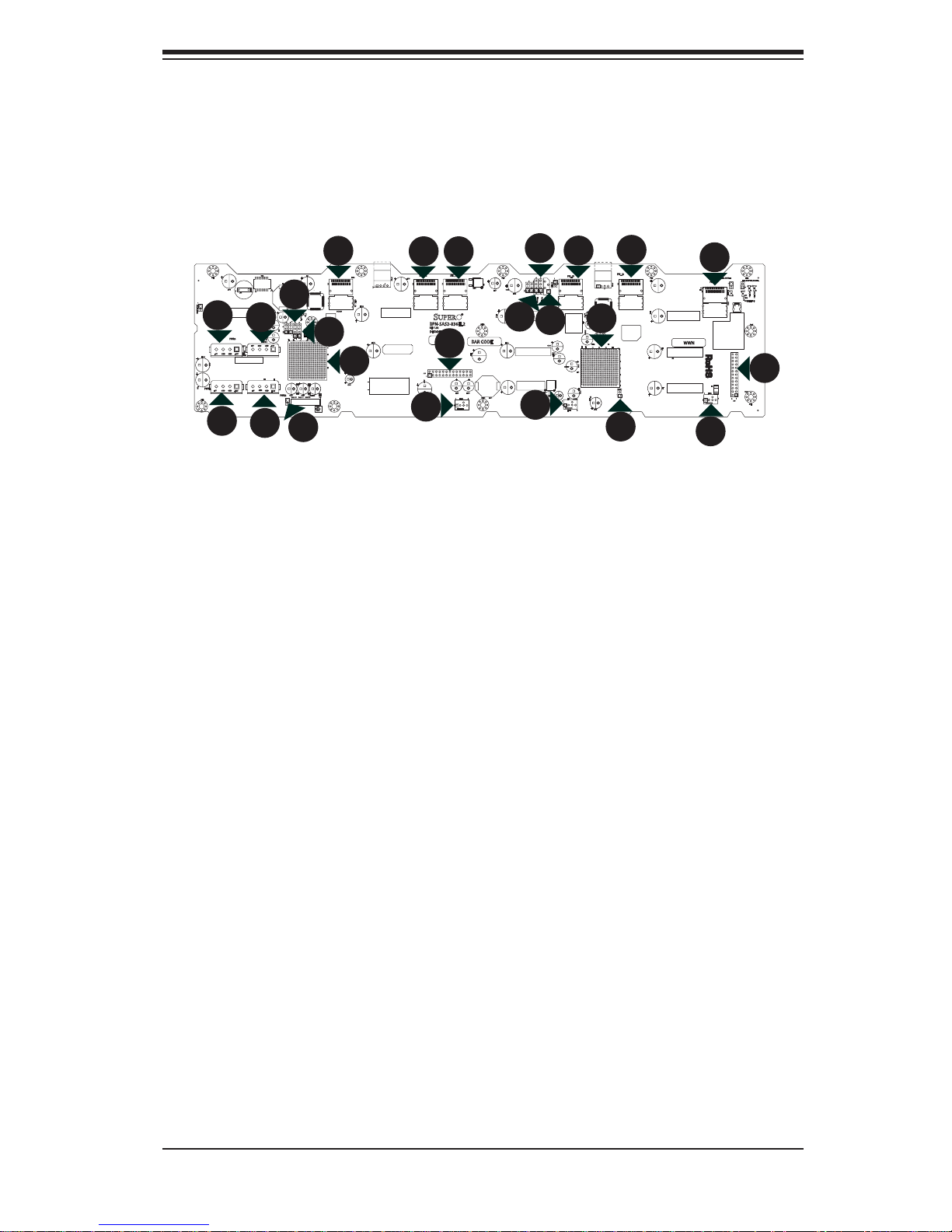
Front Connectors
Primary I1.
Power connectors: PWR1, PWR2, 2.
PWR3 and PWR4
2
C connector: PRI_I2C1
10
11
1
1
SEC_J2
EC15
BPN-SAS2-836EL2
REV 1.02
DESIGNED IN USA
J19
1
C227
+
EC17
6
1
SEC_J1
+
C421
MH10
WWN
BAR CODE
5
+
1
EC27
+
EC26+EC28
MH12
41 FAN1
JP105
R284
+
3
1
SEC_J3
EC18
+
EC16
+
4
1
+
+
C363
Figure 2-1: Front Connectors
13
1
4
4
MH9
+
Q3
C182
EC5
+
EC14
EC11
+
+
L121
+
15
1
3
3
ACTLED1
EC12
1
1
1
PRI_I2C1
UART_P1
EXPDBG1
PRI_MODE1
PRI_MODE2
1
1
1
+
C134
C121
+
+
+
+
C60
C129
6
1
Secondary SAS connector SEC_12.
J3 (Not available on SAS2-836EL1 backplane)
9
1
PRI_J3
+
C120
BCA14
L41
BCA26
L18
1
4
FAN2
8
1
PRI_J2
MH6
+
JP106
3
K
U3
17
1
EC10
+
5
+
1510
2825
MDIO1
+
1
A
ACT17
C
U14
+
3
1
BCA64
C132
AH
AE
R20E
Y
+
C133
+
C119
7
1
FANFAIL_LED_DISABLE
MH4
FAN_MONITOR_DISABLE
PRI_J1
1
C
C
1
C154
FANFAIL1
A
A
12V_LED1
5V_LED1
C
A
C
A
R162
OVERHEATFAIL1
C292
MH5
WWN
EC7
D4
5
EC9
F3
FAN31
6
1
1
C212
4
1
2
J16
MH8
Primary expander chip3.
Secondary expander chip (Not 4.
available on SAS2-836EL1 backplane)
EPP connectors: J16 and J195.
Fan connectors: FAN1, FAN2 and 6.
FAN3
Primaray SAS connector: PRI_J17.
Primary SAS connector: PRI_J28.
Primary SAS connector: PRI_J39.
Secondary SAS connector: SEC_10.
J1 (Not available on SAS2-836EL1
backplane)
Secondary SAS connector SEC_J2 11.
(Not available on SAS2-836EL1
backplane)
Primary UART connector: UART_13.
P1 (Manufacturer's use only)
Secondary UART connector: 14.
UART_S1 (Manufacturer's use
only, not present on SAS2-836EL1 backplane)
Primary debug connector: EXP-15.
DBG1 (Manufacturer's use only)
Secondary debug connector: 16.
EXPDBG2 (Manufacturer's use
only, not present on SAS2-836EL1 backplane)
Primary MDIO connector: MDIO1 17.
(Manufacturer's use only)
Secondary MDIO connector: 18.
MDIO2 (Manufacturer's use only,
not present on SAS2-836EL1
backplane)
2-1
SAS2-836EL Backplane User's Guide
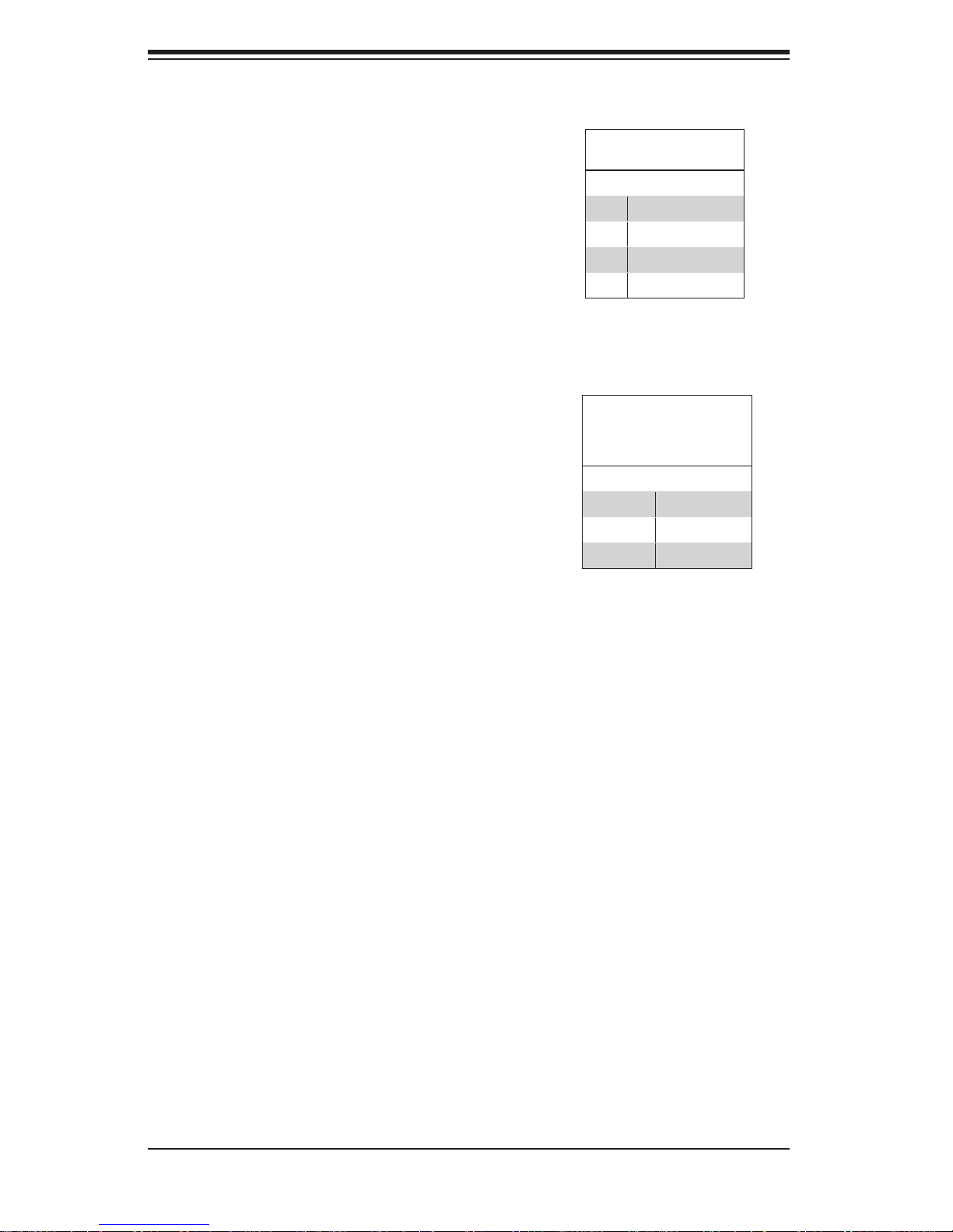
2-2 Front Connector and Pin Defi nitions
1. Primary I2C Connector
2
The I
C connector is used to monitor the power
supply status and to control the fans. See the
table on the right for pin defi nitions.
2. Backplane Main Power Connectors
The 4-pin connectors, designated PWR1,
PWR2, PWR3 and PWR4, provide power
to the backplane. See the table on the right
for pin defi nitions.
I2C Connector
Pin Defi nitions
Pin# Defi nition
1 Data
2 Ground
3 Clock
4 No Connection
Backplane
Main Power
4-Pin Connector
Pin# Defi nition
1 +12V
2 and 3 Ground
4 +5V
3. and 4. Primary and Secondary Expander
Chips
These primary and secondary expander
chips allow the backplane to support dual
ports, cascading, and failover.
5. EPP Ports
The EPP ports are used for manufacturer
diagnostic purposes only.
2-2
SAS2-836EL Backplane User's Guide
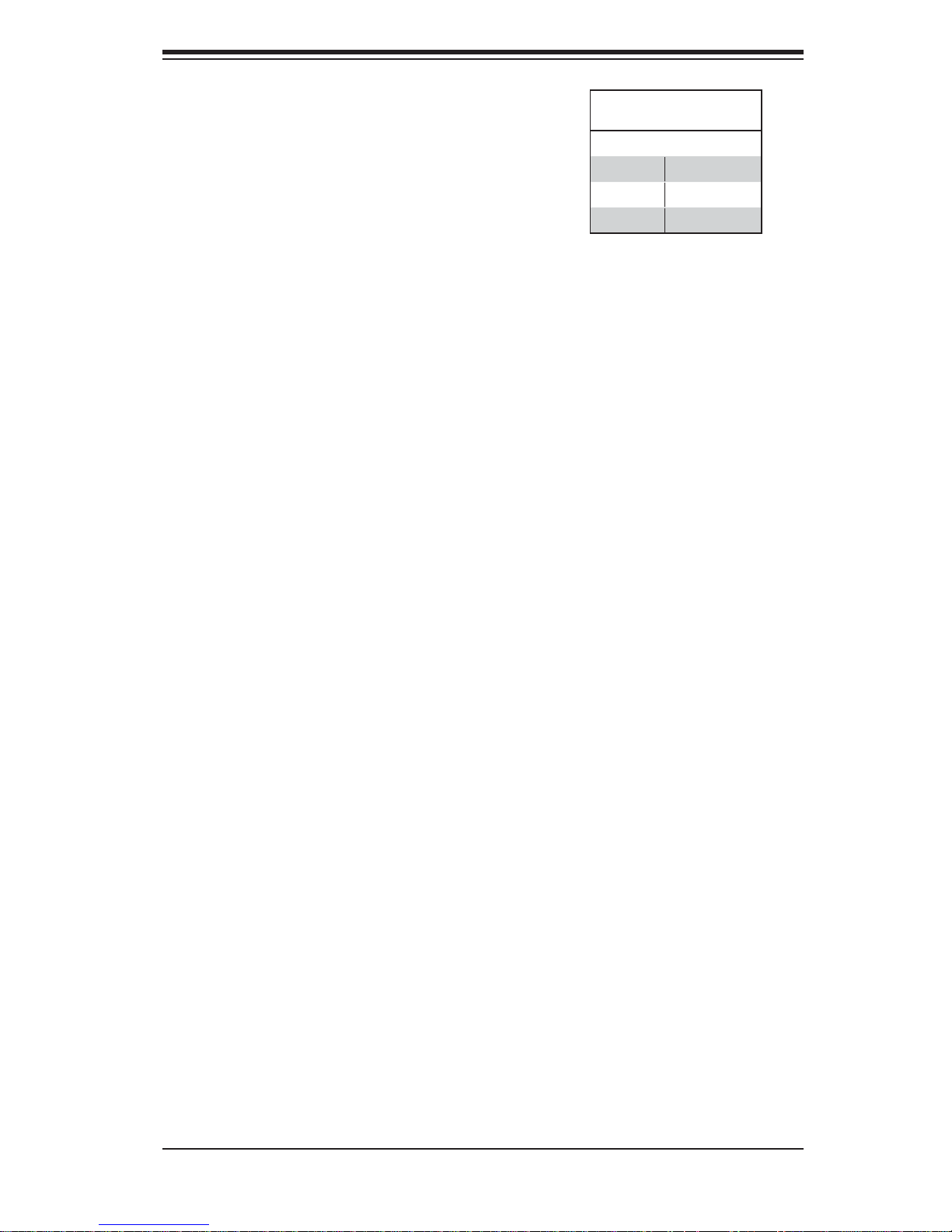
6. Fan Connectors
The 3-pin connectors, designated FAN1
through FAN3, provide power to the fans.
See the table on the right for pin defi ni-
tions.
7. - 12. SAS Connectors
The primary and secondary sets of SAS
connectors provide expander features including cascading and failover. From right
to left the ports are Primary 1, Primary 2,
Primary 3 and Secondary 1, Secondary 2
and Secondary 3. Note that secondary SAS
ports are not present on the SAS2-836EL1
backplane.
Fan Connectors
Pin# Defi nition
1 Ground
2 +12V
3 Tachometer
13. - 14. UART Connectors
The primary and secondary UART connectors are for manufacturer's diagnostic
purposes only. (The secondary UART connector is not present on the SAS2-836EL1
model backplane)
15. - 16. Debug Connectors
The primary and secondary EXPDBG1 and
EXPDBG2 connectors are for manufacturer's diagnostic purposes only. (The secondary EXPDBG2 connector is not present on
the SAS2-836EL1 model backplane)
17. - 18. MDIO Connectors
The primary and secondary MDIO1 and
MDIO2 connectors are for Supermicro's
internal use only. (The secondary MDIO2
connector is not present on the SAS2-836EL1 model backplane)
2-3
 Loading...