

Page 1
SUPER
®
SAS-216EL1/EL2
BACKPLANE
USER'S GUIDE
Rev. 1.0
Page 2

SAS-216EL Backplane User's Guide
The information in this User’s Manual has been carefully reviewed and is believed to be accurate.
The vendor assumes no responsibility for any inaccuracies that may be contained in this document,
makes no commitment to update or to keep current the information in this manual, or to notify any
person or organization of the updates. Please Note: For the most up-to-date version of this
manual, please see our web site at www.supermicro.com.
Super Micro Computer, Inc. ("Supermicro") reserves the right to make changes to the product
described in this manual at any time and without notice. This product, including software, if any,
and documentation may not, in whole or in part, be copied, photocopied, reproduced, translated or
reduced to any medium or machine without prior written consent.
IN NO EVENT WILL SUPERMICRO BE LIABLE FOR DIRECT, INDIRECT, SPECIAL, INCIDENTAL,
SPECULATIVE OR CONSEQUENTIAL DAMAGES ARISING FROM THE USE OR INABILITY TO
USE THIS PRODUCT OR DOCUMENTATION, EVEN IF ADVISED OF THE POSSIBILITY OF
SUCH DAMAGES. IN PARTICULAR, SUPERMICRO SHALL NOT HAVE LIABILITY FOR ANY
HARDWARE, SOFTWARE, OR DATA STORED OR USED WITH THE PRODUCT, INCLUDING THE
COSTS OF REPAIRING, REPLACING, INTEGRATING, INSTALLING OR RECOVERING SUCH
HARDWARE, SOFTWARE, OR DATA.
Any disputes arising between manufacturer and customer shall be governed by the laws of Santa
Clara County in the State of California, USA. The State of California, County of Santa Clara shall
be the exclusive venue for the resolution of any such disputes. Super Micro's total liability for
all claims will not exceed the price paid for the hardware product.
FCC Statement: This equipment has been tested and found to comply with the limits for a Class
A digital device pursuant to Part 15 of the FCC Rules. These limits are designed to provide
reasonable protection against harmful interference when the equipment is operated in a commercial
environment. This equipment generates, uses, and can radiate radio frequency energy and, if not
installed and used in accordance with the manufacturer’s instruction manual, may cause harmful
interference with radio communications. Operation of this equipment in a residential area is likely
to cause harmful interference, in which case you will be required to correct the interference at your
own expense.
California Best Management Practices Regulations for Perchlorate Materials: This Perchlorate
warning applies only to products containing CR (Manganese Dioxide) Lithium coin cells. “Perchlorate
Material-special handling may apply. See www.dtsc.ca.gov/hazardouswaste/perchlorate”
WARNING: Handling of lead solder materials used in this
product may expose you to lead, a chemical known to
the State of California to cause birth defects and other
reproductive harm.
Manual Revision 1.1
Release Date: July 7, 2008
Unless you request and receive written permission from Super Micro Computer, Inc., you may not
copy any part of this document.
Information in this document is subject to change without notice. Other products and companies
referred to herein are trademarks or registered trademarks of their respective companies or mark
holders.
Copyright © 2008 by Super Micro Computer, Inc.
All rights reserved.
Printed in the United States of America
ii
Page 3

Safety Information and Technical Specifi cations
Table of Contents
Contacting Supermicro ........................................................................................v
Returning Merchandise for Service ...................................................................vi
Overview of the SAS-216EL1/EL2 Backplanes ................................................ vii
Chapter 1 Safety Guidelines
1-1 ESD Safety Guidelines ................................................................................... 1-1
1-2 General Safety Guidelines .............................................................................. 1-1
1-3 An Important Note to Users ............................................................................ 1-2
Chapter 2 Jumper Settings and Pin Defi nitions
2-1 Rear Components, Connectors and Jumpers ................................................ 2-1
Rear Components and Connectors ................................................................ 2-1
2-2 Rear Connector and Pin Defi nitions ............................................................... 2-2
2-3 Rear Jumper Locations and Pin Defi nitions ................................................... 2-3
Explanation of Jumpers .................................................................................. 2-3
2-4 Front Connectors and LED Indicators ............................................................ 2-5
2-5 Front Connectors and Jumpers ...................................................................... 2-7
Chapter 3 Dual Port and Cascading Confi gurations
3-1 Single and Dual Port Expanders .................................................................... 3-1
Single Ports ..................................................................................................... 3-1
Dual Ports ....................................................................................................... 3-1
3-2 Failover ............................................................................................................ 3-2
Single Host Bus Adapter ................................................................................. 3-2
Single Host Bus Adapter Failover ................................................................... 3-2
Dual Host Bus Adapter .................................................................................. 3-2
Dual Host Bus Adapter Failover ................................................................. 3-2
3-3 Chassis Power Card and Support Cables ...................................................... 3-3
Chassis Power Card ....................................................................................... 3-3
Connectioning an Internal Host Bus Adapter to the Backplane .................... 3-4
Supported Internal HBA Cables ...................................................................... 3-4
Connecting an External Host Bus Adapter to the Backplane ........................ 3-6
Single External Host Bus Adapter ................................................................. 3-6
Dual External Host Bus Adapter .................................................................... 3-6
Supported External HBA to Backplane Cable ................................................ 3-7
Connecting Multiple Backplanes in a Single Channel Environment ............... 3-8
Single HBA Confi guration Cables ................................................................... 3-9
Connecting Multiple Backplanes in a Dual Channel Environment ............... 3-10
iii
Page 4

SAS-216EL Backplane User's Guide
Dual HBA Confi guration Cables .....................................................................3-11
3-4 Supported Cascading Confi gurations ........................................................... 3-12
Server System with Single SAS HBA ........................................................... 3-13
Dual SAS HBA and Cascaded Confi guration ............................................... 3-14
Dual SAS HBA and Cascaded Confi guration with Branching ...................... 3-15
iv
Page 5

Safety Information and Technical Specifi cations
Contacting Supermicro
Headquarters
Address: Super Micro Computer, Inc.
980 Rock Ave.
San Jose, CA 95131 U.S.A.
Tel: +1 (408) 503-8000
Fax: +1 (408) 503-8008
Email: marketing@supermicro.com (General Information)
support@supermicro.com (Technical Support)
Web
Site:
Europe
Address: Super Micro Computer B.V.
Tel: +31 (0) 73-6400390
Fax: +31 (0) 73-6416525
Email: sales@supermicro.nl (General Information)
Asia-Pacifi c
Address: Super Micro Computer, Inc.
www.supermicro.com
Het Sterrenbeeld 28, 5215 ML
's-Hertogenbosch, The Netherlands
support@supermicro.nl (Technical Support)
rma@supermicro.nl (Customer Support)
Tel: +886-(2) 8226-3990
Fax: +886-(2) 8226-3991
Web
Site:
Technical Support:
Email: support@supermicro.com.tw
Tel: 886-2-8226-1900
4F, No. 232-1, Liancheng Rd.
Chung-Ho 235, Taipei County
Taiwan, R.O.C.
www.supermicro.com.tw
v
Page 6

SAS-216EL Backplane User's Guide
Returning Merchandise for Service
A receipt or copy of your invoice marked with the date of purchase is required be-
fore any warranty service will be rendered. You can obtain service by calling your
vendor for a Returned Merchandise Authorization (RMA) number. When returning
to the manufacturer, the RMA number should be prominently displayed on the
outside of the shipping carton, and mailed prepaid or hand-carried. Shipping and
handling charges will be applied for all orders that must be mailed when service
is complete.
For faster service, RMA authorizations may be requested online (http://www.
supermicro.com/support/rma/).
Whenever possible, repack the backplane in the original Supermicro box, using the
original packaging materials. If these are no longer available, be sure to pack the
backplane in an anti-static bag and inside the box. Make sure that there is enough
packaging material surrounding the backplane so that it does not become damaged
during shipping.
This warranty only covers normal consumer use and does not cover damages in-
curred in shipping or from failure due to the alteration, misuse, abuse or improper
maintenance of products.
During the warranty period, contact your distributor fi rst for any product problems.
vi
Page 7
Safety Information and Technical Specifi cations
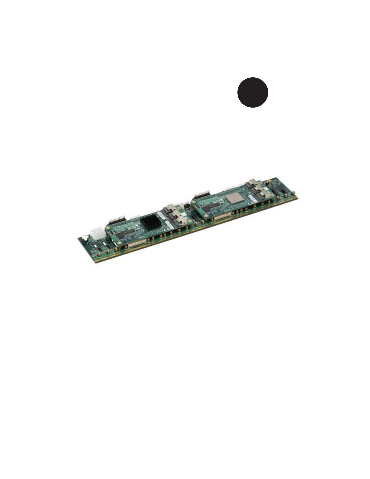
Overview of the SAS-216EL1/EL2 Backplanes
The SAS-216EL1/EL2 series of backplanes consists of a SAS-216EB backplane
(A) with one or two SAS-216EL daughter cards (B and C) mounted on the rear of
the backplane.
The SAS-216EL1 model consists of the SAS-216EB backplane (A) and one SAS-
216EL daughter card (C), mounted on the right-hand side of the backplane.
The SAS-216EL2 model consists of the SAS-216EB backplane (A), and two
SAS216EL daughter cards (B and C), mounted on the rear of the backplane.
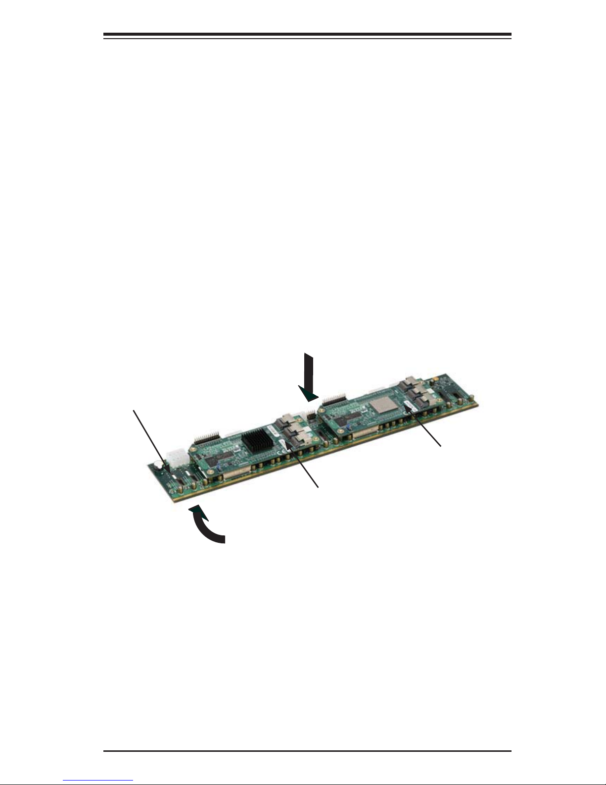
Components on the front side of the SAS-216ELB backplane include 24 SAS con-
nectors and their respecitve activity and failure LEDs. Components on the rear side
of the backplane include jumpers and power and fan connectors. The daughter
card's components include SAS ports, fl ash and expander chips, and mode select
jumpers.
SAS-216EB Backplane (A)
Front Side of the Backplane
Rear Side of the Backplane
SAS-216EL Daughter Card (C)
SAS-216EL Daughter Card (B)
vii
Page 8

Safety Information and Technical Specifi cations
Chapter 1
Safety Guidelines
To avoid personal injury and property damage, carefully follow all the safety
steps listed below when accessing your system or handling the components.
1-1 ESD Safety Guidelines
Electric Static Discharge (ESD) can damage electronic com ponents. To prevent dam-
age to your system, it is important to handle it very carefully. The following measures
are generally suffi cient to protect your equipment from ESD.
Use a grounded wrist strap designed to prevent static discharge.
•
Touch a grounded metal object before removing a component from the antistatic
•
bag.
Handle the backplane and daughter cards by their edges only; do not touch its
•
components, peripheral chips, memory modules or gold contacts.
When handling chips or modules, avoid touching their pins.
•
Put the card and peripherals back into their antistatic bags when not in use.
•
1-2 General Safety Guidelines
Always disconnect power cables before installing or removing any components
•
from the computer, including the backplane.
Disconnect the power cable before installing or removing any cables from the
•
backplane.
Make sure that the backplane is securely and properly installed on the mother-
•
board to prevent damage to the system due to power shortage.
1-1
Page 9

SAS-216EL Backplane User's Guide
1-3 An Important Note to Users
All images and layouts shown in this user's guide are based upon the latest
•
PCB Revision available at the time of publishing. The card you have received
may or may not look exactly the same as the graphics shown in this manual.
1-2
Page 10
Safety Information and Technical Specifi cations
MH1
MH2
MH3
MH4
BC1
C340
C341
C342
C343
C344
C345
C326
C327
C334
C335
C336
C337
C338
C339
C346
C347
C348
C349
C350
C351
C103
C105
C106
C107
C111
C113
C118
C120
C123
C124
C126
C127
C129
C130
C132
C133
C135
C138
C146
C153
C155
C157
C158
C159
C162
C166
C168
C172
C178
C88
C90
C94
C98
C261
C76
C171
C78
C73
BC2
C240
C241
C242
C243
C244
C245
C246
C247
C248
C249
C250
C251
C252
C253
L51
L10
L15
L17
L23
L25
L28
L3
L32
L34
L39
L40
L41
L43
L45
L46
L47
L50
L52
L55
L58
L59
L6
L60
L61
L62
L65
L66
L67
L68
L69
L8
R96
R112
R71
R72
R73
R75
R76
R77
R78
R79
R85
R86
R87
R88
R89
R91
R101
R102
R103
R104
R105
R106
R108
R74
R95
RA3
R97
R98
R99
R8
R5
R11
D1
PRI_MODE1
U2
J2
PRI_J3
PRI_J2
PRI_J1
PRI_FLASH1
PRI_SRAM1
PRI_EXP1
1
3
1
2
WWN
BAR CODE
Rev:1.01
BPN-SAS216EL
R123
R122
F10
F11
F12
F13
F14
F15
F4
F5
F6
F7
F8
F9
U3
PWR1
PWR2
PWR3
PWR4
PWR5
PWR6
BC1
BC17
BC19
BC21
BC23
BC34
BC36
BC37
BC38
BC4
BC51
BC52
BC54
BC56
BC6
BC66
BC69
BC7
BC71
BC72
BC82
BC85
BC87
BC88
BC11
BC15
BC16
BC25
BC27
BC29
BC31
BC41
BC43
BC45
BC47
BC57
BC59
BC61
BC63
BC73
BC75
BC77
BC79
BC89
BC9
BC91
BC93
BC95
BC18
BC2
BC20
BC22
BC3
BC33
BC35
BC39
BC40
BC49
BC5
BC50
BC53
BC55
BC65
BC67
BC68
BC70
BC8
BC81
BC83
BC84
BC86
P2
P1
BC10
BC12
BC13
BC14
BC26
BC28
BC30
BC32
BC42
BC44
BC46
BC48
BC58
BC60
BC62
BC64
BC74
BC76
BC78
BC80
BC90
BC92
BC94
BC96
C147
BUZZER1
C117
C141
C142
C143
C144
C21
C22
C23
C24
C45
C46
C47
C69
C70
C71
C93
C95
C48
C146
EC1
EC10
EC11
EC12
EC13
EC14
EC15
EC16
EC18
EC2
EC20
EC21
EC24
EC3
EC4
EC5
EC6
EC7
EC8
EC9
EC17
EC19
EC22
EC23
EC25
F1
F2
F3
12V_LED1
5V_LED1
FANFAIL1
OVERHEATFAIL1
BUZZER_ENB1
REMOTE_FAN_FAIL_SCOKET1
R56
R55
R54
R60
R66
R34
R36
R37
R39
R43
R44
R57
R49
R52
FAN2
FAN1
FAN3
Q5
U8
J24
J25
+5V
+12V
GND
GND
+5V
+12V
GND
GND
+5V
+12V
GND
GND
+5V
+12V
GND
GND
+5V
+12V
GND
GND
+5V
+12V
GND
GND
B1
A1
A15
B15
A29
B29
A43
A56
B56
B43
B1
A1
A15
B15
A29
B29
A43
A56
B56
B43
+
+
+
+
+
+
+
+
+
+
+
+
+
+
+
+
+
+
+
+
+
+
+
+
+
A
C
A
C
A
C
A
C
1
1
3
1
3
3
6
7
6
64
2
63
Chapter 2
Jumper Settings and Pin Defi nitions
2-1 Rear Components, Connectors and Jumpers
888
8
R49
R52
C146
REMOTE_FAN_FAIL_SCOKET1
R57
+5V
+12V
GND
BUZZER_ENB1
PWR5
+5V
+12V
GND
GND
BUZZER1
F15
+5V
GND
F14
+
8
U3
A1
+12V
GND
PWR6
F9
B1
P2
F8
GND
1
1
C147
A15
B15
PWR4
A
A
F7
C
C
F13
A29
A43
FANFAIL1
OVERHEATFAIL1
B29
B43
FAN3
PWR3
+5V
+12V
GND
GND
113
F3
R56
A56
B56
F12
F6
A1
B1
77
FAN2
R55
113
F2
P1
A15
A29
B15
B29
8
7
PWR1
+5V
+12V
GND
+5V
GND
F5
A43
B43
GND
+12V
GND
PWR2
F11
A56
B56
FAN1
3
1
F4
F10
R123
R122
R54
F1
R60
12V_LED1
5V_LED1
A
A
Q5
C
C
R66
+
6
6
EC25
7
U8
BC8
BC4
BC37
BC47
BC38
BC45
BC39
BC46
BC48
BC33
+
C22
C21
EC9
EC12
BC41
BC34
BC23
BC43
BC44
+++
C23
C24
R44
BC7
EC8
BC3
BC29
BC31
C45
BC30
C46
BC35
BC32
BC42
+
2
J25
R37
R39
EC6
R43
63
6
J2
MH1
PRI_FLASH1
1
MH4
1
2
C153
C168
C172
C155
C157
C158
C159
C162
C240
C249
C243
C241
C245
C246
C247
C248
C250
C251
C252
R103
R73
R78
RA3
R99
R96
R71
R77
R87
R91
R101
R102
R97
R76
R72
R75
R88
R89
R104
R105
R106
R108
C350
C351
C338
C339
C346
C349
C337
C348
C253
C347
C244
C242
R86
R98
R85
R79
R95
R74
D1
U2
C76
C78
R11
C178
1
3
PRI_MODE1
C341
C342
C343
C344
C345
C334
C335
C336
L59
L60
L61
L66
C326
C340
C327
BC1
C73
C171
R5
R8
BC2
R112
Rev:1.01
C261
PRI_SRAM1
Daughter Card
C129
C132
C123
C126
C135
C138
C146
C166
L3
L39
L45
L46
L50
L52
L55
L58
L62
L65
L67
L68
L69
BC40
BC36
BC19
BC21
BC27
BC28
BC22
+
+
C47
EC11
EC5
R36
R34
BC17
BC6
BC25
BC26
+
C48
EC1
BC15
BC16
BC18
BC20
BC13
BC14
BC5
+
+
+
C70
C69
BC1
BC2
EC4
EC2
EC7
BC9
BC11
BC10
BC12
+
+
C71
EC3
EC10
BC88
BC95
BC84
BC96
C95
+
+
C93
EC22
EC24
Backplane
C118
C120
C124
C127
C113
C94
C98
C106
C111
C90
C107
C130
C88
C103
C105
C133
WWN
L6
L8
L10
L15
L17
L23
L25
L28
L32
L34
L41
L43
L47
L51
L40
PRI_EXP1
BAR CODE
MH2
PRI_J1
PRI_J2
3
4
MH3
PRI_J3
5
BC85
BC49
BC89
BC66
BC71
BC92
BC93
BC86
BC90
BC94
BC67
+
64
C117
J24
EC18
BC75
BC77
BC79
BC78
BC68
BC65
BC76
+
+
BC80
EC23
+
BC72
BC83
EC17
EC19
6
J2
MH1
D1
PRI_FLASH1
1
MH4
1
2
C153
C168
C172
C155
C157
C158
C159
C240
C249
C243
C241
C245
C246
C247
C248
C250
C251
C252
R103
R73
R78
RA3
R99
R96
R71
R77
R87
R91
R101
R102
R97
R76
R72
R75
R88
R89
R104
R105
R106
R108
C350
C351
C338
C339
C346
C349
C337
C348
C253
C347
C244
C242
R86
R98
R85
R79
R95
R74
U2
C76
C78
R11
R112
C178
1
3
PRI_MODE1
C341
C342
C343
C344
C345
C334
C335
C336
L59
L66
C326
C340
C327
BC1
C73
C171
R5
R8
BC2
Rev:1.01
C261
PRI_SRAM1
Daughter Card
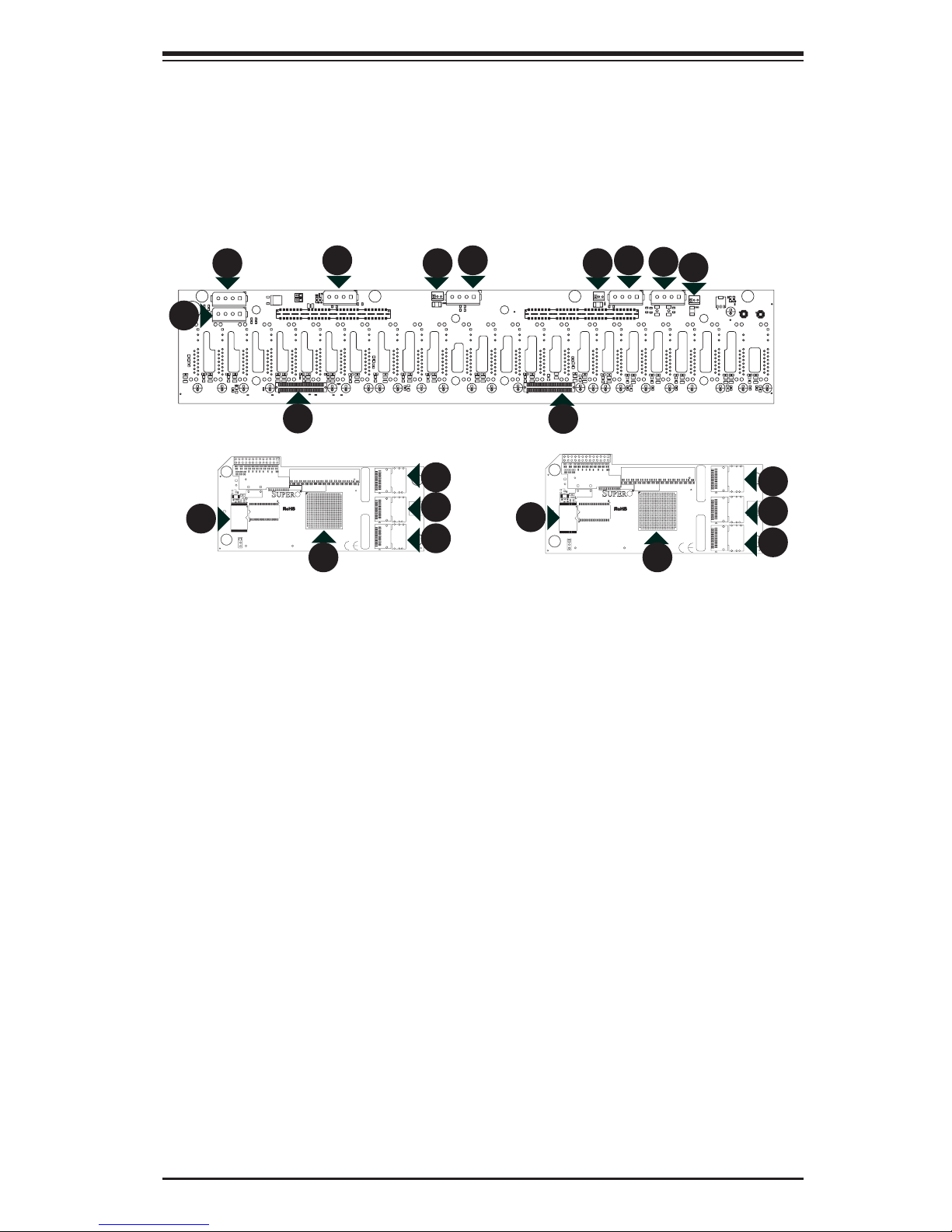
Figure 1-1: Front Connectors on Backplane and Daughter Cards
Rear Components and Connectors
Components
Primary Flash Chip
1.
BC69
BC73
BC52
BC53
BC64
BC70
BC74
+
+
BC82
C141
BC51
EC14
EC20
C118
C120
C113
C94
C98
C106
C129
C132
C111
C90
C107
C88
C103
C105
C123
C126
C135
C138
C146
C162
C166
L6
L8
L10
L15
L17
L23
L25
L28
L32
L34
L41
L3
L39
L45
L46
L50
L52
L55
L58
L60
L61
L62
L65
L67
L68
L69
PRI_EXP1
22
BC59
BC56
BC57
BC61
BC63
BC60
BC58
BC50
BC62
+
+
+
+
C144
C143
C142
BC91
BC87
BC81
EC13
EC16
C124
C127
C130
C133
WWN
L43
L47
L51
L40
PRI_J1
PRI_J2
BAR CODE
PRI_J3
EC21
EC15
BC54
BC55
MH2
3
4
MH3
5
Primary Expander Chip
2.
SAS Port: PRI_J1
3.
SAS Port: PRI_J2
4.
SAS Port: PRI_J3
5.
EPP Connectors: J24 and J25
6.
Fan Connectors: Fan1, Fan2, and Fan3
7.
Power Connectors: PWR1 - PWR6
8.
2-1
Page 11

SAS-216EL Backplane User's Guide
2-2 Rear Connector and Pin Defi nitions
1. Primary Flash Chips
The Primary Flash Chip enhances the back-
plane memory.
2. Expander Chips
This Expander Chip allows the backplane
to support dual ports, cascading, and
failover.
3. - 5. SAS Ports
The primary and secondary sets of SAS
ports provide expander features including
cascading and failover From right to left
the ports are Primary 1/2/3 and Second-
ary 1/2/3.
6. EPP Ports
The EPP ports are used for manufacturer
diagnostic purposes only.
7. Fan Connectors
The 3-pin connectors, designated FAN1,
FAN2, and FAN3, provide power to the
fans. See the table on the right for pin
defi nitions.
8. Backplane Main Power Connectors
The 4-pin connectors, designated PWR1,
PWR2, PWR3, PWR4, PWR5, and PWR6,
provide power to the backplane. See the
table on the right for pin defi nitions.
Fan Connectors
Pin# Defi nition
1 Ground
2 +12V
3 Tachometer
Backplane
Main Power
4-Pin Connector
Pin# Defi nition
1 +12V
2 and 3 Ground
4 +5V
2-2
Page 12

Safety Information and Technical Specifi cations
R123
R122
F10
F11
F12
F13
F14
F15
F4
F5
F6
F7
F8
F9
U3
PWR1
PWR2
PWR3
PWR4
PWR5
PWR6
BC1
BC17
BC19
BC21
BC23
BC34
BC36
BC37
BC38
BC4
BC51
BC52
BC54
BC56
BC6
BC66
BC69
BC7
BC71
BC72
BC82
BC85
BC87
BC88
BC11
BC15
BC16
BC25
BC27
BC29
BC31
BC41
BC43
BC45
BC47
BC57
BC59
BC61
BC63
BC73
BC75
BC77
BC79
BC89
BC9
BC91
BC93
BC95
BC18
BC2
BC20
BC22
BC3
BC33
BC35
BC39
BC40
BC49
BC5
BC50
BC53
BC55
BC65
BC67
BC68
BC70
BC8
BC81
BC83
BC84
BC86
P2
P1
BC10
BC12
BC13
BC14
BC26
BC28
BC30
BC32
BC42
BC44
BC46
BC48
BC58
BC60
BC62
BC64
BC74
BC76
BC78
BC80
BC90
BC92
BC94
BC96
C147
BUZZER1
C117
C141
C142
C143
C144
C21
C22
C23
C24
C45
C46
C47
C69
C70
C71
C93
C95
C48
C146
EC1
EC10
EC11
EC12
EC13
EC14
EC15
EC16
EC18
EC2
EC20
EC21
EC24
EC3
EC4
EC5
EC6
EC7
EC8
EC9
EC17
EC19
EC22
EC23
EC25
F1
F2
F3
12V_LED1
5V_LED1
FANFAIL1
OVERHEATFAIL1
BUZZER_ENB1
REMOTE_FAN_FAIL_SCOKET1
R56
R55
R54
R60
R66
R34
R36
R37
R39
R43
R44
R57
R49
R52
FAN2
FAN1
FAN3
Q5
U8
J24
J25
+5V
+12V
GND
GND
+5V
+12V
GND
GND
+5V
+12V
GND
GND
+5V
+12V
GND
GND
+5V
+12V
GND
GND
+5V
+12V
GND
GND
B1
A1
A15
B15
A29
B29
A43
A56
B56
B43
B1
A1
A15
B15
A29
B29
A43
A56
B56
B43
+
+
+
+
+
+
+
+
+
+
+
+
+
+
+
+
+
+
+
+
+
+
+
+
+
A
C
A
C
A
C
A
C
1
1
3
1
3
3
6
7
6
64
2
63
F12
F13F13
F6
F7
U3U3
PWR3
PWR4
P2P2
P1
C147C147
C146C146
F3
FANFAIL1FANFAIL1
OVERHEATFAIL1OVERHEATFAIL1
BUZZER_ENB1BUZZER_ENB1
REMOTE_FAN_FAIL_SCOKET1REMOTE_FAN_FAIL_SCOKET1
R56
R57R57
R49R49
R52R52
FAN3
+5V+5V+12V DGNDGND
B1B1
A1A1
A15A15
B15B15
A29
BB29
A43 A56
B56B43 B1
A1
A15
B15
AA
CCAACC
11
11
13
MH1
MH2
MH3
MH4
BC1
C340
C341
C342
C343
C344
C345
C326
C327
C334
C335
C336
C337
C338
C339
C346
C347
C348
C349
C350
C351
C103
C105
C106
C107
C111
C113
C118
C120
C123
C124
C126
C127
C129
C130
C132
C133
C135
C138
C146
C153
C155
C157
C158
C159
C162
C166
C168
C172
C178
C88
C90
C94
C98
C261
C76
C171
C78
C73
BC2
C240
C241
C242
C243
C244
C245
C246
C247
C248
C249
C250
C251
C252
C253
L51
L10
L15
L17
L23
L25
L28
L3
L32
L34
L39
L40
L41
L43
L45
L46
L47
L50
L52
L55
L58
L59
L6
L60
L61
L62
L65
L66
L67
L68
L69
L8
R96
R112
R71
R72
R73
R75
R76
R77
R78
R79
R85
R86
R87
R88
R89
R91
R101
R102
R103
R104
R105
R106
R108
R74
R95
RA3
R97
R98
R99
R8
R5
R11
D1
PRI_MODE1
U2
J2
PRI_J3
PRI_J2
PRI_J1
PRI_FLASH1
PRI_SRAM1
PRI_EXP1
1
3
1
2
WWN
BAR CODE
Rev:1.01
BPN-SAS216EL
BC1
C340
C341
C342
C343
C344
C345
C326
C327
C334
C335
C336
C337
C338
C339
C346
C347
C348
C349
C350
C351
C103
C105
C106
C107
C111
C113
C118
C120
C123
C124
C126
C127
C129
C130
C132
C133
C135
C138
C146
C153
C155
C157
C158
C159
C162
C166
C168
C172
C178
C88
C90
C94
C98
C261
C76
C171
C78
C73
BC2
C240
C241
C242
C243
C244
C245 C246 C247C248
C249
C250C251C252
C253
L51
L10
L15
L17
L23
L25
L28
L3
L32
L34
L39
L40
L41
L43
L45
L46
L47
L50
L52
L55
L58
L59L6L60
L61
L62
L65
L66
L67
L68
L69
L8
R96
R112
R71
R72
R73
R75
R76
R77
R78
R79
R85
R86
R87
R88
R89
R91
R101
R102
R103
R104
R105
R106
R108
R74
R95
RA3
R97
R98
R99
R8
R5
R11
D1
PRI_MODE1PRI_MODE1
U2
J2
PRI_J3
PRI_J2
PRI_J1
PRI_FLASH1
PRI_SRAM1
PRI_EXP1
11 33
1
2
WWN
BAR CODE
Rev:1.01
BPN-SAS216EL
2-3 Rear Jumper Locations and Pin Defi nitions
BUZZER_ENB1
REMOTE_FAN_
FAIL_SOCKET1
R49
R52
C146
REMOTE_FAN_FAIL_SCOKET1
R57
+5V
+12V
GND
BUZZER_ENB1
PWR5
+5V
+12V
GND
GND
BUZZER1
F15
+5V
GND
F14
+
U3
A1
+12V
GND
PWR6
F9
B1
P2
F8
GND
1
1
C147
A15
B15
PWR4
A
A
F7
C
C
F13
A29
A43
FANFAIL1
OVERHEATFAIL1
B29
B43
FAN3
PWR3
+5V
+12V
GND
GND
113
F3
R56
A56
B56
F12
F6
A1
B1
FAN2
R55
113
F2
P1
A15
A29
B15
B29
B43
+5V
GND
+5V
GND
F5
A43
GND
+12V
GND
PWR2
F11
F4
F10
R123
R122
A56
B56
PWR1
R60
+12V
1
F1
12V_LED1
5V_LED1
A
A
Q5
FAN1
C
C
R66
3
+
R54
6
6
EC25
7
U8
BC8
BC4
BC37
BC47
BC38
BC45
BC39
BC46
BC48
BC33
+
C22
C21
EC9
EC12
J2
MH1
C243
C241
C245
C251
C252
R78
R99
R96
R71
R77
R87
R91
R101
R102
R97
C346
C348
C253
C347
C244
C242
R86
R98
R85
R79
R95
R74
D1
BC1
U2
C76
C73
C78
C171
R5
R11
R8
BC2
R112
C178
PRI_FLASH1
MH4
1
3
PRI_MODE1
Explanation of Jumpers
To modify the operation of the backplane,
jumpers can be used to choose between
BC41
BC43
BC44
+++
C23
R44
BC7
EC8
BC3
1
2
C240
C249
C246
C250
R103
R76
R72
R88
R89
R104
R105
R106
C338
C339
C337
C326
C340
C327
C261
PRI_SRAM1
PRI_Mode1
BC34
BC31
C45
BC35
BC32
BC42
+
2
C24
J25
R37
EC6
R43
C153
C168
C129
C132
C172
C123
C126
C135
C138
C155
C157
C158
C159
C162
C247
C248
R73
RA3
R75
R108
C350
C351
C349
C341
C342
C343
C344
C345
C334
C335
C336
L39
L45
L46
L50
L52
L59
L60
L61
L62
L66
L67
L68
L69
Rev:1.01
Figure 1-2: Front Jumper Locations and Pin Defi mitions
optional settings. Jumpers create shorts
between two pins to change the function
of the connector. Pin 1 is identifi ed with
a square solder pad on the printed circuit
board. Note: On two pin jumpers, "Closed"
means the jumper is on and "Open" means
the jumper is off the pins.
BC23
BC27
BC29
BC28
BC30
C46
+
C47
EC5
R39
R34
63
C113
C94
C98
C106
C111
C90
C107
C88
C146
C166
L6
L8
L10
L15
L23
L25
L28
L3
L55
L58
L65
PRI_EXP1
BC40
BC36
BC19
BC21
BC22
+
EC11
R36
C118
C120
C103
C105
L17
L32
L34
BC17
BC6
BC20
WWN
BC15
BC16
BC18
BC13
BC14
BC5
+
+
+
C70
C69
BC1
BC2
EC4
EC2
EC7
PRI_J1
PRI_J2
BC25
BC26
+
C48
EC1
C124
C127
C130
C133
L41
L43
L47
L51
L40
BC9
BC11
BC10
BC12
+
+
C71
EC3
EC10
MH2
BAR CODE
MH3
PRI_J3
BC88
BC95
BC84
BC96
C95
+
+
C93
EC22
EC24
J2
MH1
C243
R71
R97
C242
R85
R79
R74
D1
C76
PRI_FLASH1
MH4
1
3
PRI_MODE1
BC85
BC49
BC89
BC66
BC92
BC93
BC86
BC90
BC94
J24
C241
C245
C252
R78
R99
R96
R87
R91
C348
C253
C244
R86
R98
R95
BC1
U2
C73
C78
R11
BC2
R112
C178
BC79
BC67
C250
C251
R77
R101
R102
R89
R104
C346
C347
C326
C171
R5
R8
BC78
BC68
+
+
64
BC80
EC23
C117
EC18
EC19
1
2
C153
C168
C172
C155
C157
C240
C249
C246
C247
C248
R103
R73
RA3
R76
R72
R75
R88
R105
R106
R108
C350
C351
C338
C339
C349
C337
C341
C342
C343
C344
C345
C334
C335
C336
C340
C327
Rev:1.01
C261
PRI_SRAM1
BC69
BC71
BC73
BC75
BC77
BC65
+
+
BC72
EC17
C129
C132
C123
C126
C158
C159
C162
L39
L45
L46
L59
L60
L61
L62
L66
L67
L68
L69
BC52
BC53
BC76
BC83
C135
C138
L50
L52
BC64
BC70
BC74
+
+
BC82
C141
BC51
EC14
EC20
C118
C120
C124
C127
C113
C94
C98
C106
C111
C90
C107
C88
C103
C105
C146
C166
L6
L8
L10
L15
L17
L23
L25
L28
L32
L34
L41
L43
L40
L3
L55
L58
L65
PRI_EXP1
BC59
BC61
BC63
BC60
BC62
+
+
+
C143
C142
BC87
BC81
EC13
WWN
EC15
PRI_J1
PRI_J2
EC16
C130
C133
L47
L51
BAR CODE
PRI_J3
PRI_Mode1
2-3
321
Connector
Pins
Jumper
Setting
321
BC56
BC57
BC58
BC50
+
C144
BC91
EC21
BC54
BC55
MH2
MH3
Page 13

SAS-216EL Backplane User's Guide
General Jumper Settings
Jumper Jumper Settings Note
PRI_MODE1 1-2
BUZZER_ENB1
Open: Disable
Closed: Enable
Socket Settings
Socket Socket Setting Note
REMOTE_FAN_FAIL_
SOCKET1
Connected
Front Panel LEDs
LED STATE SPECIFICATION
12V_LED1 OFF
5V_LED1 OFF
Factory Setting
Do not change
Buzzer Enable
Front Panel Fan Fail indicator
(Optional)
Backplane power failure. Light is on during
normal operation.
Backplane power failure. Light is on during
normal operation.
2-4
Page 14

Safety Information and Technical Specifi cations
D26
D27
D29
D28
D30
D32
D33
D34
D35
D31
D36
D38
D39
D40
D41
D42
D43
D44
D45
D46
D47
D25
D37
D49
D51
D52
D53
D54
D55
D56
D57
D58
D59
D60
D61
D62
D63
D64
D65
D66
D67
D68
D69
D70
D71
D72
D50
D48
MH10
MH11
MH12
MH2
MH4
MH5
MH7
MH9
MH3
MH6
MH8
J23
J22
J3
J4
J8
J9
J21
J20
J2
J19
J18
J17
J16
J15
J14
J13
J12
J11
J10
J1
J0
J5
J7
C98
C1
C10
C100
C101
C102
C103
C104
C105
C106
C107
C108
C109
C11
C110
C111
C112
C12
C122
C128
C13
C130
C126
C14
C15
C16
C2
C25
C26
C27
C28
C29
C3
C30
C31
C32
C33
C34
C35
C36
C37
C38
C39
C4
C40
C49
C5
C50
C51
C52
C53
C54
C55
C56
C57
C58
C59
C6
C60
C61
C62
C63
C64
C7
C73
C74
C75
C76
C77
C78
C79
C8
C80
C81
C82
C83
C84
C85
C86
C87
C88
C9
C97
C99
C145
FAIL0
ACT0
ACT1
ACT10
ACT11
ACT12
ACT13
ACT14
ACT15
ACT16
ACT17
ACT18
ACT19
ACT2
ACT20
ACT21
ACT22
ACT23
ACT3
ACT4
ACT5
ACT6
ACT7
ACT8
ACT9
FAIL1
FAIL10
FAIL11
FAIL12
FAIL13
FAIL14
FAIL15
FAIL16
FAIL17
FAIL18
FAIL19
FAIL2
FAIL20
FAIL21
FAIL22
FAIL23
FAIL3
FAIL4
FAIL5
FAIL6
FAIL7
FAIL8
FAIL9
R1
R10
R11
R12
R13
R15
R18
R2
R20
R21
R22
R23
R24
R25
R26
R27
R28
R29
R3
R30
R31
R32
R33
R35
R38
R4
R40
R41
R42
R45
R46
R47
R48
R5
R6
R7
R8
R9
R53
D1
D10
D11
D12
D13
D14
D15
D16
D17
D18
D19
D2
D20
D21
D22
D23
D24
D3
D4
D6
D7
D8
D9
U1
BAR CODE
22
21
33
27
8
7
9
22
21
33
27
8
7
9
22
21
33
27
8
7
9
22
21
33
27
8
7
9
22
21
33
27
8
7
9
22
21
33
27
8
7
9
22
21
33
27
8
7
9
22
21
33
27
8
7
9
22
21
33
27
8
9
22
21
33
27
8
7
9
22
21
33
27
8
7
9
22
21
33
27
8
7
9
22
21
33
27
8
7
9
22
21
33
27
8
7
9
22
21
33
27
8
7
9
22
21
33
27
8
7
9
22
21
33
27
8
7
9
22
21
33
27
8
7
9
22
21
33
27
8
7
9
22
21
33
27
8
9
22
21
33
27
8
7
9
22
21
33
27
8
7
9
22
21
33
27
8
7
9
22
21
33
27
8
7
9
A
C
A
C
A
C
A
C
A
C
C
C
C
A
A
C
A
C
A
C
A
C
C
A
C
A
C
C
A
C
A
C
A
C
A
C
A
C
A
C
A
C
A
C
C
A
C
A
C
C
C
C
C
C
A
C
A
C
A
C
A
C
C
A
A
C
A
C
A
C
A
C
A
C
A
C
A
C
A
C
DESIGNED IN USA
Rev:1.01
BPN-SAS216EB
2-4 Front Connectors and LED Indicators
BPN-SAS216EB
Rev:1.01
SAS #J0
SAS #J1
DESIGNED IN USA
7
27
27
33
8
8
8
33
9
9
21
21
D29
D30
D27
D28
22
22
R3
22
J1
J0
D26
D25
D1
R1
D2
R2
C
A
R7
C
A
A
C
R4
C
A
ACT0
FAIL0
ACT1
FAIL1
SAS #J2
SAS #J3
MH2
C128
C99
C108
C122
7
7
27
27
33
9
21
J2
R5
FAIL2
C
A
27
C130
C111
C126
C112
8
8
33
33
9
9
21
21
MH12
D33
D34
22
22
D32
D31
J3
J4
D4
D3
R6
R9
ACT3
FAIL4
ACT2
FAIL3
R11
R8
A
C
C
C
C
A
A
A
SAS #J4
SAS #J5
SAS #J6
C107
C98
C103
C104
D35
D36
ACT4
D5D5D6
A
C
C102
C97
C105
C106
7
7
27
27
7
C101
C109
C110
C100
8
8
33
33
8
9
9
21
21
D38
D37
D39
D40
22
22
22
J5
J6J6J7
D7
R10
R13
FAIL6
ACT5
FAIL5
ACT6
R15
R12
A
A
C
C
C
C
A
A
MH3
SAS #J7
SAS #J8
C84
C80
27
27
7
C87
C88
8
33
33
9
9
21
21
D44
D41
D42
22
J8
D9
D8
ACT8
FAIL8
ACT7
FAIL7
A
A
A
C
C
C
A
C
MH4
SAS #J9
SAS #J10
C77
C76
C83
C78
C73
C79
7
27
27
7
C86
C81
C75
C82
8
33
33
8
9
9
21
21
MH11
D43
D45
D46
22
22
J9
J10
R23
R18
D11
R20
R21
D10
CCAAC
AAC
A
A
A
C
C
ACT10
ACT9
FAIL10
FAIL9
SAS #J11
C54
7
C55
27
7
C85
C63
C74
C64
8
33
9
8
21
22
22
D50
D49
J11
J12
D47
R22
D48
D12
D13
A
C
A
R24
ACT11
FAIL11
FAIL12
SAS #J12
SAS #J13
SAS #J14
MH5
C145
R53
C52
U1
C53
27
C57
C58
33
9
21
MH10
D14
R25
R27
C
C
A
ACT12
C49
C60
C51
C50
27
27
7
7
7
C59
C56
33
33
8
8
22
8
9
9
21
21
22
22
D51
D52
D53
D54
J14
J13
R26
R28
R29
R31
D16
D15
AAC
AAC
AAC
AAC
ACT13
ACT14
FAIL13
FAIL14
MH6
SAS #J15
SAS #J16
SAS #J17
C27
C33
C34
C35
27
27
7
27
7
C37
C39
C61
C62
33
9
21
D56
J15
R32
R30
AAC
AAC
ACT15
FAIL15
C38
C40
33
33
8
9
8
9
21
21
22
22
D55
D57
D58
D62
J17
J16
D59
D60
R33
D18
AAC
AAC
CCA
A
D17
R35
ACT16
ACT17
FAIL17
FAIL16
SAS #J18
SAS #J19
C25
C28
C26
C32
7
8
22
D61
D19
C
7
7
27
27
C30
C29
C31
C36
33
33
8
9
9
8
21
21
22
22
D63
D64
D65
D66
J19
J18
A
FAIL18
J20
R38
R40
A
A
A
A
C
C
C
C
D21
D20
ACT18
ACT19
FAIL19
FAIL20
MH7
SAS #J20
SAS #J21
C4
C10
C9
C6
7
27
27
C13
C15
C14
C16
33
33
8
9
9
21
21
MH9
22
D67
D68
J21
R41
R42
D22
A
C
AAC
AAC
C
ACT21
FAIL21
ACT20
Rear SAS/SATA Connectors
Front
Connector
SAS #J0 SAS/SATA HDD #1 SAS #J12 SAS/SATA HDD #13
SAS #J1 SAS/SATA HDD #2 SAS #J13 SAS/SATA HDD #14
SAS #J2 SAS/SATA HDD #3 SAS #J14 SAS/SATA HDD #15
SAS #J3 SAS/SATA HDD #4 SAS #J15 SAS/SATA HDD #16
SAS #J4
SAS #J5 SAS/SATA HDD #6 SAS #J17 SAS/SATA HDD #18
SAS #J6 SAS/SATA HDD #7 SAS #J18 SAS/SATA HDD #19
SAS Drive
Number
SAS/SATA HDD #5
Front
Connector
SAS #J16
SAS Drive
Number
SAS/SATA HDD #17
MH8
SAS #J22
SAS #J23
BAR CODE
C2
C3
C8
C1
7
27
27
7
C11
C12
C7
C5
33
8
33
8
9
9
21
21
22
22
D71
D72
J23
J22
R45
D69
D70
D23
D24
R46
R47
R48
AAC
C
A
C
A
CCA
ACT23
ACT22
FAIL23
FAIL22
SAS #J7 SAS/SATA HDD #8 SAS #J19 SAS/SATA HDD #20
SAS #J8 SAS/SATA HDD #9 SAS #J20 SAS/SATA HDD #21
SAS #J9 SAS/SATA HDD #10 SAS #J21 SAS/SATA HDD #22
SAS #J10 SAS/SATA HDD #11 SAS #J22 SAS/SATA HDD #23
SAS #J11 SAS/SATA HDD #12 SAS #J23 SAS/SATA HDD #24
2-5
Page 15

SAS-216EL Backplane User's Guide
Front LED Indicators
Front LED Hard Drive Activity Failure LED
SAS #J0 ACT #1 FAIL #1
SAS #J1 ACT #2 FAIL #2
SAS #J2 ACT #3 FAIL #3
SAS #J3 ACT #4 FAIL #4
SAS #J4 ACT #5 FAIL #5
SAS #J5 ACT #6 FAIL #6
SAS #J6 ACT #7 FAIL #7
SAS #J7 ACT #8 FAIL #8
SAS #J8 ACT #9 FAIL #9
SAS #J9 ACT #10 FAIL #10
SAS #J10 ACT #11 FAIL #11
SAS #J11 ACT #12 FAIL #12
SAS #J12 ACT #13 FAIL #13
SAS #J13 ACT #14 FAIL #14
SAS #J14 ACT #15 FAIL #15
SAS #J15 ACT #16 FAIL #16
SAS #J16 ACT #17 FAIL #17
SAS #J17 ACT #18 FAIL #18
SAS #J18 ACT #19 FAIL #19
SAS #J19 ACT #20 FAIL #20
SAS #J20 ACT #21 FAIL #21
SAS #J21 ACT #22 FAIL #22
SAS #J22 ACT #23 FAIL #23
SAS #J23 ACT #24 FAIL #24
2-6
Page 16

Safety Information and Technical Specifi cations
2-5 Front Connectors and Jumpers
Front Components
Power Connectors: PWR1, PWR2, PWR3, PWR4, PWR5, and PWR61.
2-7
Page 17

Safety Information and Technical Specifi cations
MH1
MH2
MH3
MH4
BC1
C340
C341
C342
C343
C344
C345
C326
C327
C334
C335
C336
C337
C338
C339
C346
C347
C348
C349
C350
C351
C103
C105
C106
C107
C111
C113
C118
C120
C123
C124
C126
C127
C129
C130
C132
C133
C135
C138
C146
C153
C155
C157
C158
C159
C162
C166
C168
C172
C178
C88
C90
C94
C98
C261
C76
C171
C78
C73
BC2
C240
C241
C242
C243
C244
C245
C246
C247
C248
C249
C250
C251
C252
C253
L51
L10
L15
L17
L23
L25
L28
L3
L32
L34
L39
L40
L41
L43
L45
L46
L47
L50
L52
L55
L58
L59
L6
L60
L61
L62
L65
L66
L67
L68
L69
L8
R96
R112
R71
R72
R73
R75
R76
R77
R78
R79
R85
R86
R87
R88
R89
R91
R101
R102
R103
R104
R105
R106
R108
R74
R95
RA3
R97
R98
R99
R8
R5
R11
D1
PRI_MODE1
U2
J2
PRI_J3
PRI_J2
PRI_J1
PRI_FLASH1
PRI_SRAM1
PRI_EXP1
1
3
1
2
WWN
BAR CODE
Rev:1.01
BPN-SAS216EL
Chapter 3
Dual Port and Cascading Confi gurations
3-1 Single and Dual Port Expanders
Single Ports
SAS-216EL1 backplanes have a single-port expander on the daughter card, that
accesses all 24 drives and supports cascading.
Port A
Primary Ports
Expander 1
J2
MH1
C243
C241
C245
C252
R78
R99
R96
R71
R87
R91
R102
R97
C348
C253
C347
C244
C242
R86
R98
R85
R79
R95
R74
D1
BC1
U2
C76
C73
C78
R5
R11
R8
BC2
R112
C178
PRI_FLASH1
MH4
1
3
PRI_MODE1
1
2
C153
C168
C240
C249
C246
C247
C248
C250
C251
R103
R73
RA3
R77
R101
R76
R72
R75
R88
R89
R104
R105
R106
R108
C350
C351
C338
C339
C346
C349
C337
C334
C335
C326
C340
C327
C171
Rev:1.01
C261
PRI_SRAM1
From HBA or higher
backplane
C118
C120
C124
C127
C113
C94
C98
C106
C129
C132
C172
C111
C90
C107
C130
C88
C103
C105
C123
C126
C135
C155
C157
C158
C159
C162
C341
C342
C343
C344
C345
C336
L39
L45
L46
L59
L60
L61
L62
L66
L67
L68
L69
C133
C138
C146
C166
L50
L52
L55
L58
L65
WWN
L6
L8
L10
L15
L17
L23
L25
L28
L32
L34
L41
L43
L47
L51
L40
J1
L3
PRI_EXP1
J2
BAR CODE
J3
MH2
PRI_J1
PRI_J2
MH3
PRI_J3
To Lower Backplane in
Cascaded System
Figure 3-1: SAS-216EL2 Single Port Confi guration
Dual Ports
SAS-216EL2 backplanes have dual-port expanders on the daughter cards, that
access all 24 drives. These dual-port expanders support cascading, failover, and
recovery.
From HBA or higher
backplane
C118
C120
C124
C127
C113
C94
C98
C106
C129
C132
C111
C90
C107
C130
C88
C103
C105
C123
C126
C135
C155
C157
C158
C159
C162
C341
C343
C344
L39
L45
L46
L50
L59
L60
L61
L62
L66
L67
L68
L69
C133
C138
C146
C166
L3
L52
L55
L58
L65
WWN
L6
L8
L10
L15
L17
L23
L25
L28
L32
L34
L41
L43
L47
L51
L40
J1
PRI_EXP1
PRI_J1
PRI_J2
J2
BAR CODE
J3
PRI_J3
MH2
MH3
Port B
Secondary Ports
Expander 2
J2
MH1
D1
C76
PRI_FLASH1
MH4
1
3
PRI_MODE1
1
2
C153
C168
C129
C132
C172
C123
C126
C135
C138
C155
C157
C158
C159
C162
C240
C249
C243
C241
C245
C246
C247
C248
C250
C251
C252
R103
R73
R78
RA3
R99
R96
R71
R77
R87
R91
R101
R102
R97
R76
R72
R75
R88
R89
R104
R105
R106
R108
C350
C351
C338
C339
C346
C349
C337
C348
C253
C347
C244
C242
R86
R98
R85
R79
R95
R74
BC1
U2
C73
C78
R11
BC2
R112
C178
C341
C342
C343
C344
C345
C334
C335
C336
L39
L45
L46
L50
L52
L55
L59
L60
L61
L62
L66
L67
L68
C326
C340
C327
C171
R5
R8
L69
Rev:1.01
C261
PRI_SRAM1
From HBA or higher
backplane
C118
C120
C124
C127
C113
C94
C98
C106
C111
C90
C107
C130
C88
C103
C105
C133
C146
C166
L58
L65
WWN
L6
L8
L10
L15
L17
L23
L25
L28
L32
L34
L41
L43
L47
L51
L40
J1
L3
PRI_EXP1
PRI_J1
PRI_J2
J2
BAR CODE
J3
PRI_J3
MH2
MH3
Port A
Primary Ports
Expander 1
J2
MH1
D1
C76
PRI_FLASH1
MH4
1
3
PRI_MODE1
1
2
C153
C168
C172
C240
C249
C243
C241
C245
C246
C247
C248
C250
C251
C252
R103
R73
R78
RA3
R99
R96
R71
R77
R87
R91
R101
R102
R97
R76
R72
R75
R88
R89
R104
R105
R106
R108
C350
C351
C338
C339
C346
C349
C337
C348
C253
C347
C244
C242
R86
R98
R85
R79
R95
R74
U2
C73
C78
R11
R112
C178
C342
C345
C334
C335
C336
C326
C340
C327
BC1
C171
R5
R8
BC2
Rev:1.01
C261
PRI_SRAM1
Figure 3-2: SAS-216EL2 Dual Port Confi guration
To Lower Backplane in
Cascaded System
3-1
To Lower Backplane in
Cascaded System
Page 18

SAS-216EL Backplane User's Guide
MH1
MH2
MH3
MH4
BC1
C340
C341
C342
C343
C344
C345
C326
C327
C334
C335
C336
C337
C338
C339
C346
C347
C348
C349
C350
C351
C103
C105
C106
C107
C111
C113
C118
C120
C123
C124
C126
C127
C129
C130
C132
C133
C135
C138
C146
C153
C155
C157
C158
C159
C162
C166
C168
C172
C178
C88
C90
C94
C98
C261
C76
C171
C78
C73
BC2
C240
C241
C242
C243
C244
C245
C246
C247
C248
C249
C250
C251
C252
C253
L51
L10
L15
L17
L23
L25
L28
L3
L32
L34
L39
L40
L41
L43
L45
L46
L47
L50
L52
L55
L58
L59
L6
L60
L61
L62
L65
L66
L67
L68
L69
L8
R96
R112
R71
R72
R73
R75
R76
R77
R78
R79
R85
R86
R87
R88
R89
R91
R101
R102
R103
R104
R105
R106
R108
R74
R95
RA3
R97
R98
R99
R8
R5
R11
D1
PRI_MODE1
U2
J2
PRI_J3
PRI_J2
PRI_J1
PRI_FLASH1
PRI_SRAM1
PRI_EXP1
1
3
1
2
WWN
BAR CODE
Rev:1.01
BPN-SAS216EL
3-2 Failover
The SAS-216EL2 backplane has two expanders which allow effective failover and
recovery.
Single Host Bus Adapter
In a single host bus confi guration, the
backplane connects to one Host Bus
Adapter (HBA).
SAS HBA
J2
1
2
MH1
C153
C168
C94
C129
C132
C172
C111
C90
C107
C88
C123
C126
C135
C138
C146
C155
C157
C158
C159
C162
C166
C240
C249
C243
C241
C245
C246
C247
C248
C250
C251
C252
R103
R73
R78
RA3
R99
R96
R71
R77
R87
R91
R101
R102
R97
R76
R72
R75
R88
R89
R104
R105
R106
R108
C350
C351
C338
C339
C346
C349
C337
C348
C253
C347
C244
C242
R86
R98
R85
C341
C342
C343
C344
C345
C334
C335
C336
R79
R95
R74
D1
C76
PRI_FLASH1
MH4
1
3
PRI_MODE1
L6
L8
L23
L25
L3
L39
L45
L46
L50
L52
L55
L58
L59
L60
L61
L62
L65
L66
L67
L68
L69
C326
C340
C327
PRI_EXP1
BC1
U2
C73
C78
C171
R5
R11
R8
BC2
R112
C178
Rev:1.01
C261
PRI_SRAM1
Port B
Expander 2
Figure 3-3: Single HBA
J2
1
2
C118
C120
C124
C127
C113
C98
C106
C130
C103
C105
C133
MH2
WWN
L10
L15
L17
L28
L32
L34
L41
L43
L47
L51
L40
PRI_J1
PRI_J2
BAR CODE
MH3
PRI_J3
MH1
C243
C241
C245
C251
C252
R78
R99
R96
R71
R77
R87
R91
R101
R102
R97
R89
C346
C348
C253
C347
C244
C242
R86
R98
R85
R79
R95
R74
D1
C326
BC1
U2
C76
C73
C78
C171
R5
R11
R8
BC2
R112
C178
PRI_FLASH1
MH4
1
3
PRI_MODE1
C118
C153
C168
C113
C94
C98
C106
C129
C132
C172
C111
C90
C107
C88
C103
C105
C123
C126
C135
C138
C146
C155
C157
C158
C159
C162
C166
C240
C249
C246
C247
C248
C250
R103
R73
RA3
R76
R72
R75
R88
R104
R105
R106
R108
C350
C351
C338
C339
C349
C337
C341
C342
C343
C344
C345
C334
C335
C336
L6
L8
L10
L15
L17
L23
L25
L28
L32
L34
L3
L39
L45
L46
L50
L52
L55
L58
L59
L60
L61
L62
L65
L66
L67
L68
L69
C340
C327
PRI_EXP1
Rev:1.01
C261
PRI_SRAM1
Port A
Expander 1
C120
C124
C127
C130
C133
MH2
WWN
L41
L43
L47
L51
L40
PRI_J1
PRI_J2
BAR CODE
MH3
PRI_J3
Single Host Bus Adapter
Failover
If the expander or data path in Port A
fails, the system automatically switches
to Port B.
Dual Host Bus Adapter
In a Dual Host Bus Confi guration, the
backplane connects to two Host Bus
Adapters (HBA).
SAS HBA
J2
1
2
MH1
C243
C241
C245
C250
C251
C252
R78
R99
R96
R71
R77
R87
R91
R101
R102
R97
R89
R104
C346
C348
C253
C347
C244
C242
R86
R98
R85
R79
R95
R74
D1
C326
BC1
U2
C76
C73
C78
C171
R5
R11
R8
BC2
R112
C178
PRI_FLASH1
MH4
1
3
PRI_MODE1
C118
C120
C124
C127
C153
C168
C113
C94
C98
C106
C129
C132
C172
C111
C90
C107
C130
C88
C103
C105
C123
C126
C133
C135
C138
C146
C155
C157
C158
C159
C162
C166
C240
C249
C246
C247
C248
R103
R73
RA3
R76
R72
R75
R88
R105
R106
R108
C350
C351
C338
C339
C349
C337
C341
C342
C343
C344
C345
C334
C335
C336
L6
L8
L23
L25
L3
L39
L45
L46
L50
L52
L55
L58
L59
L60
L61
L62
L65
L66
L67
L68
L69
C340
C327
PRI_EXP1
Rev:1.01
C261
PRI_SRAM1
MH2
WWN
L10
L15
L17
L28
L32
L34
L41
L43
L47
L51
L40
PRI_J1
PRI_J2
BAR CODE
MH3
PRI_J3
Port B
Expander 2
Figure 3-4: Single HBA Failover
J2
1
2
MH1
C153
C168
C113
C94
C98
C106
C129
C132
C172
C111
C90
C107
C88
C123
C126
C135
C138
C146
C155
C157
C158
C159
C162
C166
C240
C249
C243
C241
C245
C246
C247
C248
C250
C251
C252
R103
R73
R78
RA3
R99
R96
R71
R77
R87
R91
R101
R102
R97
R76
R72
R75
R88
R89
R104
R105
R106
R108
C350
C351
C338
C339
C346
C349
C337
C348
C253
C347
C244
C242
R86
R98
R85
C341
C342
C343
C344
C345
C334
C335
C336
R79
R95
R74
D1
C76
PRI_FLASH1
MH4
1
3
PRI_MODE1
L6
L8
L10
L15
L23
L25
L28
L3
L39
L45
L46
L50
L52
L55
L58
L59
L60
L61
L62
L65
L66
L67
L68
L69
C326
C340
C327
PRI_EXP1
BC1
U2
C73
C78
C171
R5
R11
R8
BC2
R112
C178
Rev:1.01
C261
PRI_SRAM1
Port A
Expander 1
C118
C120
C124
C127
C130
C103
C105
C133
L17
L32
L34
L41
L43
L47
L51
L40
SAS HBA
SAS HBA
J2
J2
1
2
MH1
C153
C168
C129
C132
C172
C111
C90
C107
C88
C123
C126
C135
C138
C146
C155
C157
C158
C159
C162
C166
C240
C249
C243
C241
C245
C246
C247
C248
C250
C251
C252
R103
R73
R78
RA3
R99
R96
R71
R77
R87
R91
R101
R102
R97
R76
R72
R75
R88
R89
R104
R105
R106
R108
C350
C351
C338
C339
C346
C349
C337
C348
C253
C347
C244
C242
R86
R98
R85
C341
C342
C343
C344
C345
C334
C335
C336
R79
R95
R74
D1
C76
C78
PRI_FLASH1
MH4
1
3
PRI_MODE1
L6
L8
L23
L3
L39
L45
L46
L50
L52
L55
L58
L59
L60
L61
L62
L65
L66
L67
L68
L69
C326
C340
C327
BC1
U2
C73
C171
R5
R11
R8
BC2
R112
C178
Rev:1.01
C261
PRI_SRAM1
Port B
Expander 2
C118
C120
C124
C127
C113
C94
C98
C106
C130
C103
C105
C133
MH2
WWN
L10
L15
L17
L25
L28
L32
L34
L41
L43
L47
L51
L40
PRI_EXP1
PRI_J1
PRI_J2
BAR CODE
MH3
PRI_J3
1
2
MH1
C243
C241
C245
C250
C251
C252
R78
R99
R96
R71
R77
R87
R91
R101
R102
R97
R89
C346
C348
C253
C347
C244
C242
R86
R98
R85
R79
R95
R74
D1
C326
BC1
U2
C76
C73
C78
C171
R5
R11
R8
BC2
R112
C178
PRI_FLASH1
MH4
1
3
PRI_MODE1
C118
C153
C168
C113
C94
C98
C106
C129
C132
C172
C111
C90
C107
C88
C103
C105
C123
C126
C135
C138
C146
C155
C157
C158
C159
C162
C166
C240
C249
C246
C247
C248
R103
R73
RA3
R76
R72
R75
R88
R104
R105
R106
R108
C350
C351
C338
C339
C349
C337
C341
C342
C343
C344
C345
C334
C335
C336
L6
L8
L10
L15
L17
L23
L25
L28
L32
L34
L3
L39
L45
L46
L50
L52
L55
L58
L59
L60
L61
L62
L65
L66
L67
L68
L69
C340
C327
PRI_EXP1
Rev:1.01
C261
PRI_SRAM1
Port A
Expander 1
MH2
WWN
PRI_J1
PRI_J2
BAR CODE
MH3
PRI_J3
C120
C124
C127
C130
C133
MH2
WWN
L41
L43
L47
L51
L40
PRI_J1
PRI_J2
BAR CODE
MH3
PRI_J3
Dual Host Bus Adapter
Failover
If the Expander or data path in Port A
fails, the system automatically switches
to Port B. This maintains a full connec-
tion to all drives.
3-2
Figure 3-5: Dual HBA
SAS HBA
SAS HBA
J2
J2
1
2
MH1
C243
C241
C245
C250
C251
C252
R78
R99
R96
R71
R77
R87
R91
R101
R102
R97
R89
C346
C348
C253
C347
C244
C242
R86
R98
R85
R79
R95
R74
D1
C326
BC1
U2
C76
C73
C78
C171
R5
R11
R8
BC2
R112
C178
PRI_FLASH1
MH4
1
3
PRI_MODE1
C118
C120
C124
C127
C153
C168
C113
C94
C98
C106
C129
C132
C172
C111
C90
C107
C130
C88
C103
C105
C123
C126
C133
C135
C138
C146
C155
C157
C158
C159
C162
C166
C240
C249
C246
C247
C248
R103
R73
RA3
R76
R72
R75
R88
R104
R105
R106
R108
C350
C351
C338
C339
C349
C337
C341
C342
C343
C344
C345
C334
C335
C336
L6
L8
L23
L25
L3
L39
L45
L46
L50
L52
L55
L58
L59
L60
L61
L62
L65
L66
L67
L68
L69
C340
C327
PRI_EXP1
Rev:1.01
C261
PRI_SRAM1
MH2
WWN
L10
L15
L17
L28
L32
L34
L41
L43
L47
L51
L40
PRI_J1
PRI_J2
BAR CODE
MH3
PRI_J3
Port B
Expander 2
Figure 3-6: Dual HBA Failover
1
2
MH1
C153
C168
C94
C129
C132
C172
C111
C90
C107
C88
C123
C126
C135
C138
C146
C155
C157
C158
C159
C162
C166
C240
C249
C243
C241
C245
C246
C247
C248
C250
C251
C252
R103
R73
R78
RA3
R99
R96
R71
R77
R87
R91
R101
R102
R97
R76
R72
R75
R88
R89
R104
R105
R106
R108
C350
C351
C338
C339
C346
C349
C337
C348
C253
C347
C244
C242
R86
R98
R85
C341
C342
C343
C344
C345
C334
C335
C336
R79
R95
R74
D1
C76
PRI_FLASH1
MH4
1
3
PRI_MODE1
L6
L8
L23
L25
L3
L39
L45
L46
L50
L52
L55
L58
L59
L60
L61
L62
L65
L66
L67
L68
L69
C326
C340
C327
PRI_EXP1
BC1
U2
C73
C78
C171
R5
R11
R8
BC2
R112
C178
Rev:1.01
C261
PRI_SRAM1
Port A
Expander 1
C118
C120
C124
C127
C113
C98
C106
C130
C103
C105
C133
MH2
WWN
L10
L15
L17
L28
L32
L34
L41
L43
L47
L51
L40
PRI_J1
PRI_J2
BAR CODE
MH3
PRI_J3
Page 19

Safety Information and Technical Specifi cations
A
A
A
3-3 Chassis Power Card and Support Cables
Chassis Power Card
In a cascaded confi guration, the fi rst chassis includes a motherboard and at least
one Host Bus Adapter (HBA). Other servers in this enclosed system, include a
power card. This section describes the supported power card for the SAS-846
series backplane.
For more information, see the Supermicro Web site at http://www.supermicro.
com.
AAA
JBPWR2
Figure 3-7: Chassis Power Card (Sold Separately)
REV 1.00
AAA
AAA
Part Number Part Type Where Used
CSE-PTJBOD-CB1 Power Card
Power Card
Allows the chassis to be in a
JBOD (Just a Bunch of Drives)
system.
3-3
Page 20

SAS-216EL Backplane User's Guide
MH1
MH2
MH3
MH4
BC1
C340
C341
C342
C343
C344
C345
C326
C327
C334
C335
C336
C337
C338
C339
C346
C347
C348
C349
C350
C351
C103
C105
C106
C107
C111
C113
C118
C120
C123
C124
C126
C127
C129
C130
C132
C133
C135
C138
C146
C153
C155
C157
C158
C159
C162
C166
C168
C172
C178
C88
C90
C94
C98
C261
C76
C171
C78
C73
BC2
C240
C241
C242
C243
C244
C245
C246
C247
C248
C249
C250
C251
C252
C253
L51
L10
L15
L17
L23
L25
L28
L3
L32
L34
L39
L40
L41
L43
L45
L46
L47
L50
L52
L55
L58
L59
L6
L60
L61
L62
L65
L66
L67
L68
L69
L8
R96
R112
R71
R72
R73
R75
R76
R77
R78
R79
R85
R86
R87
R88
R89
R91
R101
R102
R103
R104
R105
R106
R108
R74
R95
RA3
R97
R98
R99
R8
R5
R11
D1
PRI_MODE1
U2
J2
PRI_J3
PRI_J2
PRI_J1
PRI_FLASH1
PRI_SRAM1
PRI_EXP1
1
3
1
2
WWN
BAR CODE
Rev:1.01
BPN-SAS216EL
MH1
MH2
MH3
MH4
BC1
C340
C341
C342
C343
C344
C345
C326
C327
C334
C335
C336
C337
C338
C339
C346
C347
C348
C349
C350
C351
C103
C105
C106
C107
C111
C113
C118
C120
C123
C124
C126
C127
C129
C130
C132
C133
C135
C138
C146
C153
C155
C157
C158
C159
C162
C166
C168
C172
C178
C88
C90
C94
C98
C261
C76
C171
C78
C73
BC2
C240
C241
C242
C243
C244
C245
C246
C247
C248
C249
C250
C251
C252
C253
L51
L10
L15
L17
L23
L25
L28
L3
L32
L34
L39
L40
L41
L43
L45
L46
L47
L50
L52
L55
L58
L59
L6
L60
L61
L62
L65
L66
L67
L68
L69
L8
R96
R112
R71
R72
R73
R75
R76
R77
R78
R79
R85
R86
R87
R88
R89
R91
R101
R102
R103
R104
R105
R106
R108
R74
R95
RA3
R97
R98
R99
R8
R5
R11
D1
PRI_MODE1
U2
J2
PRI_J3
PRI_J2
PRI_J1
PRI_FLASH1
PRI_SRAM1
PRI_EXP1
1
3
1
2
WWN
BAR CODE
Rev:1.01
BPN-SAS216EL
MH1
MH2
MH3
MH4
BC1
C340
C341
C342
C343
C344
C345
C326
C327
C334
C335
C336
C337
C338
C339
C346
C347
C348
C349
C350
C351
C103
C105
C106
C107
C111
C113
C118
C120
C123
C124
C126
C127
C129
C130
C132
C133
C135
C138
C146
C153
C155
C157
C158
C159
C162
C166
C168
C172
C178
C88
C90
C94
C98
C261
C76
C171
C78
C73
BC2
C240
C241
C242
C243
C244
C245
C246
C247
C248
C249
C250
C251
C252
C253
L51
L10
L15
L17
L23
L25
L28
L3
L32
L34
L39
L40
L41
L43
L45
L46
L47
L50
L52
L55
L58
L59
L6
L60
L61
L62
L65
L66
L67
L68
L69
L8
R96
R112
R71
R72
R73
R75
R76
R77
R78
R79
R85
R86
R87
R88
R89
R91
R101
R102
R103
R104
R105
R106
R108
R74
R95
RA3
R97
R98
R99
R8
R5
R11
D1
PRI_MODE1
U2
J2
PRI_J3
PRI_J2
PRI_J1
PRI_FLASH1
PRI_SRAM1
PRI_EXP1
1
3
1
2
WWN
BAR CODE
Rev:1.01
BPN-SAS216EL
MH1
MH2
MH3
MH4
BC1
C340
C341
C342
C343
C344
C345
C326
C327
C334
C335
C336
C337
C338
C339
C346
C347
C348
C349
C350
C351
C103
C105
C106
C107
C111
C113
C118
C120
C123
C124
C126
C127
C129
C130
C132
C133
C135
C138
C146
C153
C155
C157
C158
C159
C162
C166
C168
C172
C178
C88
C90
C94
C98
C261
C76
C171
C78
C73
BC2
C240
C241
C242
C243
C244
C245
C246
C247
C248
C249
C250
C251
C252
C253
L51
L10
L15
L17
L23
L25
L28
L3
L32
L34
L39
L40
L41
L43
L45
L46
L47
L50
L52
L55
L58
L59
L6
L60
L61
L62
L65
L66
L67
L68
L69
L8
R96
R112
R71
R72
R73
R75
R76
R77
R78
R79
R85
R86
R87
R88
R89
R91
R101
R102
R103
R104
R105
R106
R108
R74
R95
RA3
R97
R98
R99
R8
R5
R11
D1
PRI_MODE1
U2
J2
PRI_J3
PRI_J2
PRI_J1
PRI_FLASH1
PRI_SRAM1
PRI_EXP1
1
3
1
2
WWN
BAR CODE
Rev:1.01
BPN-SAS216EL
Connectioning an Internal Host Bus Adapter to the
Backplane
The following section lists the most common cables used to connect the Host Bus
Adapter (HBA) to the backplane.
J2
MH1
MH4
C240
C243
C241
C245
C250
C251
C252
R103
R78
R99
R96
R71
R77
R87
R91
R101
R102
R97
R72
R89
R104
C339
C346
C348
C253
C347
C244
C242
R86
R98
R85
R79
R95
R74
D1
C326
C340
C327
BC1
U2
C76
C73
C78
C171
R5
R11
R8
BC2
R112
C178
PRI_FLASH1
1
3
PRI_MODE1
HBA
(Host Bus Adapter)
Figure 3-8: Single Internal Host Bus Adapter
J2
MH1
C243
C241
C245
C250
C251
C252
R78
R99
R96
R71
R77
R87
R91
R101
R102
R97
R72
R89
R104
C339
C346
C348
C253
C347
C244
C242
R86
R98
R85
R79
R95
R74
D1
C326
C340
BC1
U2
C76
C73
C78
C171
R5
R11
R8
BC2
R112
C178
PRI_FLASH1
MH4
1
3
PRI_MODE1
1
2
C153
C168
C172
C155
C157
C158
C159
C162
C249
C246
C247
C248
R73
RA3
R76
R75
R88
R105
R106
R108
C350
C351
C338
C349
C337
C341
C342
C343
C344
C345
C334
C335
C336
L59
L60
L61
L66
Rev:1.01
C261
PRI_SRAM1
1
2
C153
C168
C172
C155
C157
C158
C240
C249
C246
C247
C248
R103
R73
RA3
R76
R75
R88
R105
R106
R108
C350
C351
C338
C349
C337
C341
C342
C343
C344
C345
C334
C335
C336
L66
C327
Rev:1.01
C261
PRI_SRAM1
C118
C120
C124
C127
C113
C94
C98
C106
C129
C132
C111
C90
C107
C130
C88
C103
C105
C123
C126
C135
L39
L45
L46
L50
L62
L67
L68
L69
C133
C138
C146
C166
L52
L55
L58
L65
WWN
L6
L8
L10
L15
L17
L23
L25
L28
L32
L34
L41
L43
L47
L51
L40
L3
PRI_EXP1
PRI_J1
PRI_J2
MH2
BAR CODE
MH3
PRI_J3
C118
C120
C124
C127
C113
C94
C98
C106
C129
C132
C111
C90
C107
C130
C88
C103
C105
C123
C126
C135
C159
C162
L39
L45
L46
L59
L60
L61
L62
L67
L68
L69
C133
C138
C146
C166
L50
L52
L55
L58
L65
WWN
L6
L8
L10
L15
L17
L23
L25
L28
L32
L34
L41
L43
L47
L51
L40
L3
PRI_EXP1
PRI_J1
PRI_J2
MH2
BAR CODE
MH3
PRI_J3
J2
MH1
R85
D1
C76
PRI_FLASH1
MH4
1
3
PRI_MODE1
1
2
C153
C168
C172
C155
C157
C158
C159
C162
C240
C249
C243
C241
C245
C246
C247
C248
C250
C251
C252
R103
R73
R78
RA3
R99
R96
R71
R77
R87
R91
R101
R102
R97
R76
R72
R75
R88
R89
R104
R105
R106
R108
C350
C351
C338
C339
C346
C349
C337
C348
C253
C347
C244
C242
R86
R98
R79
R95
R74
BC1
U2
C73
C78
R5
R11
R8
BC2
R112
C178
J2
MH1
R71
C242
R85
R74
D1
C76
PRI_FLASH1
MH4
1
3
PRI_MODE1
C341
C342
C343
C344
C345
C334
C335
C336
L59
L60
L61
L66
C326
C340
C327
C171
Rev:1.01
C261
PRI_SRAM1
1
2
C168
C240
C249
C243
C241
C245
C246
C247
C248
C250
C251
C252
R103
R73
R78
RA3
R99
R96
R77
R87
R91
R101
R102
R97
R76
R72
R75
R88
R89
R104
R105
R106
R108
C350
C351
C338
C339
C346
C349
C337
C348
C253
C347
C244
R86
R98
C334
R79
R95
U2
C78
R11
C178
C335
C326
C340
C327
BC1
C73
C171
R5
R8
BC2
R112
Rev:1.01
C261
PRI_SRAM1
C118
C120
C124
C127
C113
C94
C98
C106
C129
C132
C111
C90
C107
C130
C88
C103
C105
C123
C126
L39
L45
L46
L62
L67
L68
L69
C133
C135
C138
C146
C166
L50
L52
L55
L58
L65
WWN
L6
L8
L10
L15
L17
L23
L25
L28
L32
L34
L41
L43
L47
L51
L40
L3
PRI_EXP1
PRI_J1
PRI_J2
MH2
BAR CODE
MH3
PRI_J3
C118
C120
C124
C153
C129
C172
C123
C126
C155
C157
C158
C159
C162
C341
C342
C343
C344
C345
C336
L59
L60
L61
L62
L66
L67
L68
L69
C127
C113
C94
C98
C106
C132
C111
C90
C107
C130
C88
C103
C105
C135
L39
L45
L46
C133
C138
C146
C166
L50
L52
L55
L58
WWN
L6
L8
L10
L15
L17
L23
L25
L28
L32
L34
L41
L43
L47
L51
L40
L3
L65
PRI_EXP1
PRI_J1
PRI_J2
MH2
BAR CODE
MH3
PRI_J3
HBA (Host Bus Adapter)
HBA (Host Bus Adapter)
Figure 3-9: Dual Internal Host Bus Adapter
Supported Internal HBA Cables
Use the following listed cables to create connections between the internal HBA and
SAS-216EL backplane. The cables required depend on the HBA connector.
Cable Name: IPASS TO 4-LANE
Part #: CBL-0117L
Length: 46 cm (18 inches)
Description: This cable has one SFF-8484 (32 pin) connector on one end and ipass
(SFF-8087/mini-sas) connector (36 pins) at the other. This cable connects from the HBA
to the SAS-216EL backplane
3-4
Page 21

Safety Information and Technical Specifi cations
Cable Name: IPASS (mini SAS) TO IPASS (mini SAS)
Part #: CBL-0108L-02 Length: 39 cm (15 inches)
Part #: CBL-0109L-02 Length: 22 cm (9 inches)
Part #: CBL-0110L-02 Length: 18 cm (7 inches)
Description: This cable has an ipass (SFF-8087/mini-sas) connector (36 pins) at each
end. It connects from the HBA to the SAS-216EL backplane.
3-5
Page 22

SAS-216EL Backplane User's Guide
MH1
MH2
MH3
MH4
BC1
C340
C341
C342
C343
C344
C345
C326
C327
C334
C335
C336
C337
C338
C339
C346
C347
C348
C349
C350
C351
C103
C105
C106
C107
C111
C113
C118
C120
C123
C124
C126
C127
C129
C130
C132
C133
C135
C138
C146
C153
C155
C157
C158
C159
C162
C166
C168
C172
C178
C88
C90
C94
C98
C261
C76
C171
C78
C73
BC2
C240
C241
C242
C243
C244
C245
C246
C247
C248
C249
C250
C251
C252
C253
L51
L10
L15
L17
L23
L25
L28
L3
L32
L34
L39
L40
L41
L43
L45
L46
L47
L50
L52
L55
L58
L59
L6
L60
L61
L62
L65
L66
L67
L68
L69
L8
R96
R112
R71
R72
R73
R75
R76
R77
R78
R79
R85
R86
R87
R88
R89
R91
R101
R102
R103
R104
R105
R106
R108
R74
R95
RA3
R97
R98
R99
R8
R5
R11
D1
PRI_MODE1
U2
J2
PRI_J3
PRI_J2
PRI_J1
PRI_FLASH1
PRI_SRAM1
PRI_EXP1
1
3
1
2
WWN
BAR CODE
Rev:1.01
BPN-SAS216EL
MH1
MH2
MH3
MH4
BC1
C340
C341
C342
C343
C344
C345
C326
C327
C334
C335
C336
C337
C338
C339
C346
C347
C348
C349
C350
C351
C103
C105
C106
C107
C111
C113
C118
C120
C123
C124
C126
C127
C129
C130
C132
C133
C135
C138
C146
C153
C155
C157
C158
C159
C162
C166
C168
C172
C178
C88
C90
C94
C98
C261
C76
C171
C78
C73
BC2
C240
C241
C242
C243
C244
C245
C246
C247
C248
C249
C250
C251
C252
C253
L51
L10
L15
L17
L23
L25
L28
L3
L32
L34
L39
L40
L41
L43
L45
L46
L47
L50
L52
L55
L58
L59
L6
L60
L61
L62
L65
L66
L67
L68
L69
L8
R96
R112
R71
R72
R73
R75
R76
R77
R78
R79
R85
R86
R87
R88
R89
R91
R101
R102
R103
R104
R105
R106
R108
R74
R95
RA3
R97
R98
R99
R8
R5
R11
D1
PRI_MODE1
U2
J2
PRI_J3
PRI_J2
PRI_J1
PRI_FLASH1
PRI_SRAM1
PRI_EXP1
1
3
1
2
WWN
BAR CODE
Rev:1.01
BPN-SAS216EL
MH1
MH2
MH3
MH4
BC1
C340
C341
C342
C343
C344
C345
C326
C327
C334
C335
C336
C337
C338
C339
C346
C347
C348
C349
C350
C351
C103
C105
C106
C107
C111
C113
C118
C120
C123
C124
C126
C127
C129
C130
C132
C133
C135
C138
C146
C153
C155
C157
C158
C159
C162
C166
C168
C172
C178
C88
C90
C94
C98
C261
C76
C171
C78
C73
BC2
C240
C241
C242
C243
C244
C245
C246
C247
C248
C249
C250
C251
C252
C253
L51
L10
L15
L17
L23
L25
L28
L3
L32
L34
L39
L40
L41
L43
L45
L46
L47
L50
L52
L55
L58
L59
L6
L60
L61
L62
L65
L66
L67
L68
L69
L8
R96
R112
R71
R72
R73
R75
R76
R77
R78
R79
R85
R86
R87
R88
R89
R91
R101
R102
R103
R104
R105
R106
R108
R74
R95
RA3
R97
R98
R99
R8
R5
R11
D1
PRI_MODE1
U2
J2
PRI_J3
PRI_J2
PRI_J1
PRI_FLASH1
PRI_SRAM1
PRI_EXP1
1
3
1
2
WWN
BAR CODE
Rev:1.01
BPN-SAS216EL
Connecting an External Host Bus Adapter to the
Backplane
This backplane supports external Host Bus Adapters. In this confi guration, the HBA
and the backplane are in different physical chassis. This allows a JBOD (Just a
Bunch Of Drives) confi guration from an existing system.
Single External Host Bus Adapter
J2
1
2
HBA
(Host Bus Adapter)
Power Card
MH1
C240
C249
C243
C241
C245
C250
C251
C252
R103
R78
R99
R96
R71
R77
R87
R91
R101
R102
R97
R76
R72
R89
R104
C338
C339
C346
C348
C253
C347
C244
C242
R86
R98
R85
R79
R95
R74
D1
C326
C340
C327
BC1
U2
C76
C73
C78
C171
R5
R11
R8
BC2
R112
C178
PRI_FLASH1
MH4
1
3
PRI_MODE1
C118
C120
C124
C127
C153
C168
C113
C94
C98
C106
C129
C132
C172
C111
C90
C107
C130
C88
C103
C105
C123
C126
C133
C135
C138
C146
C155
C157
C158
C159
C162
C166
C246
C247
C248
R73
RA3
R75
R88
R105
R106
R108
C350
C351
C349
C337
C334
C335
Rev:1.01
C261
PRI_SRAM1
WWN
C341
C342
C343
C344
C345
C336
L6
L8
L10
L15
L17
L23
L25
L28
L32
L34
L41
L43
L47
L51
L40
L3
L39
L45
L46
L50
L52
L55
L58
L59
L60
L61
L62
L65
L66
L67
L68
L69
PRI_EXP1
PRI_J1
PRI_J2
BAR CODE
PRI_J3
MH2
MH3
Figure 3-10: Single External Host Adapter
Dual External Host Bus Adapter
J2
1
2
MH1
C153
C168
C129
C132
C172
C123
C126
C135
C138
C155
C157
C158
C159
C162
C240
C249
C243
C241
C245
C246
C247
C248
C250
C251
C252
R103
R73
R78
RA3
R99
R96
R71
R77
R87
R91
R101
R102
R97
R76
R72
R75
R88
R89
R104
R105
R106
R108
C350
C351
C338
C339
C346
C349
C337
C348
C253
C347
C244
C242
R86
R98
R85
C341
C342
C343
C344
C345
C334
C335
C336
R79
R95
R74
HBA
(Host Bus Adapter)
HBA
(Host Bus Adapter)
D1
PRI_FLASH1
MH4
1
3
L39
L45
L46
L50
L52
L59
L60
L61
L62
L66
L67
L68
L69
C326
C340
C327
BC1
U2
C76
C73
C78
C171
R5
R11
R8
BC2
R112
C178
Rev:1.01
C261
PRI_SRAM1
PRI_MODE1
Power Card
CBL-0166L
External HBA Cable
J2
1
2
C118
C120
C124
C127
C113
C94
C98
C106
C111
C90
C107
C130
C88
C103
C105
C133
C146
C166
WWN
L6
L8
L10
L15
L17
L23
L25
L28
L32
L34
L41
L43
L47
L51
L40
L3
L55
L58
L65
PRI_EXP1
PRI_J1
PRI_J2
BAR CODE
PRI_J3
MH1
MH2
MH3
C240
C243
C241
C245
C250
C251
C252
R103
R78
R99
R96
R71
R77
R87
R91
R101
R102
R97
R76
R72
R89
R104
C338
C339
C346
C348
C253
C347
C244
C242
R86
R98
R85
R79
R95
R74
D1
C326
C340
C327
BC1
U2
C76
C73
C78
C171
R5
R11
R8
BC2
R112
C178
PRI_FLASH1
MH4
1
3
PRI_MODE1
C118
C120
C124
C127
C153
C168
C113
C94
C98
C106
C129
C132
C172
C111
C90
C107
C130
C88
C103
C105
C123
C126
C133
C135
C138
C146
C155
C157
C158
C159
C162
C166
C249
C246
C247
C248
R73
RA3
R75
R88
R105
R106
R108
C350
C351
C349
C337
C341
C342
C343
C344
C345
C334
C335
C336
L6
L8
L10
L15
L23
L25
L28
L3
L39
L45
L46
L50
L52
L55
L58
L59
L60
L61
L62
L65
L66
L67
L68
L69
PRI_EXP1
Rev:1.01
C261
PRI_SRAM1
MH2
WWN
L17
L32
L34
L41
L43
L47
L51
L40
PRI_J1
PRI_J2
BAR CODE
MH3
PRI_J3
Figure 3-11: Dual External Host Bus Adapter
CBL-0166L
External HBA Cables
3-6
Page 23

Safety Information and Technical Specifi cations
Supported External HBA to Backplane Cable
Use the following cable if your external HBA has an Infi niBand connector.
Figure 3-12: SAS Infi niBand Cable (CBL-0200L)
Cable Name: SAS Infi niBand to Mini SAS X4 1M cable, PBF
Part #: CBL-0200L
Length: 1 meter
Description: This cable has an Infi niBand connector (SFF-8470) on one end and an
SFF-8088-1X (26-pins) at the other end.
3-7
Page 24

SAS-216EL Backplane User's Guide
MH1
MH2
MH3
MH4
BC1
C340
C341
C342
C343
C344
C345
C326
C327
C334
C335
C336
C337
C338
C339
C346
C347
C348
C349
C350
C351
C103
C105
C106
C107
C111
C113
C118
C120
C123
C124
C126
C127
C129
C130
C132
C133
C135
C138
C146
C153
C155
C157
C158
C159
C162
C166
C168
C172
C178
C88
C90
C94
C98
C261
C76
C171
C78
C73
BC2
C240
C241
C242
C243
C244
C245
C246
C247
C248
C249
C250
C251
C252
C253
L51
L10
L15
L17
L23
L25
L28
L3
L32
L34
L39
L40
L41
L43
L45
L46
L47
L50
L52
L55
L58
L59
L6
L60
L61
L62
L65
L66
L67
L68
L69
L8
R96
R112
R71
R72
R73
R75
R76
R77
R78
R79
R85
R86
R87
R88
R89
R91
R101
R102
R103
R104
R105
R106
R108
R74
R95
RA3
R97
R98
R99
R8
R5
R11
D1
PRI_MODE1
U2
J2
PRI_J3
PRI_J2
PRI_J1
PRI_FLASH1
PRI_SRAM1
PRI_EXP1
1
3
1
2
WWN
BAR CODE
Rev:1.01
BPN-SAS216EL
MH1
MH2
MH3
MH4
BC1
C340
C341
C342
C343
C344
C345
C326
C327
C334
C335
C336
C337
C338
C339
C346
C347
C348
C349
C350
C351
C103
C105
C106
C107
C111
C113
C118
C120
C123
C124
C126
C127
C129
C130
C132
C133
C135
C138
C146
C153
C155
C157
C158
C159
C162
C166
C168
C172
C178
C88
C90
C94
C98
C261
C76
C171
C78
C73
BC2
C240
C241
C242
C243
C244
C245
C246
C247
C248
C249
C250
C251
C252
C253
L51
L10
L15
L17
L23
L25
L28
L3
L32
L34
L39
L40
L41
L43
L45
L46
L47
L50
L52
L55
L58
L59
L6
L60
L61
L62
L65
L66
L67
L68
L69
L8
R96
R112
R71
R72
R73
R75
R76
R77
R78
R79
R85
R86
R87
R88
R89
R91
R101
R102
R103
R104
R105
R106
R108
R74
R95
RA3
R97
R98
R99
R8
R5
R11
D1
PRI_MODE1
U2
J2
PRI_J3
PRI_J2
PRI_J1
PRI_FLASH1
PRI_SRAM1
PRI_EXP1
1
3
1
2
WWN
BAR CODE
Rev:1.01
BPN-SAS216EL
MH1
MH2
MH3
MH4
BC1
C340
C341
C342
C343
C344
C345
C326
C327
C334
C335
C336
C337
C338
C339
C346
C347
C348
C349
C350
C351
C103
C105
C106
C107
C111
C113
C118
C120
C123
C124
C126
C127
C129
C130
C132
C133
C135
C138
C146
C153
C155
C157
C158
C159
C162
C166
C168
C172
C178
C88
C90
C94
C98
C261
C76
C171
C78
C73
BC2
C240
C241
C242
C243
C244
C245
C246
C247
C248
C249
C250
C251
C252
C253
L51
L10
L15
L17
L23
L25
L28
L3
L32
L34
L39
L40
L41
L43
L45
L46
L47
L50
L52
L55
L58
L59
L6
L60
L61
L62
L65
L66
L67
L68
L69
L8
R96
R112
R71
R72
R73
R75
R76
R77
R78
R79
R85
R86
R87
R88
R89
R91
R101
R102
R103
R104
R105
R106
R108
R74
R95
RA3
R97
R98
R99
R8
R5
R11
D1
PRI_MODE1
U2
J2
PRI_J3
PRI_J2
PRI_J1
PRI_FLASH1
PRI_SRAM1
PRI_EXP1
1
3
1
2
WWN
BAR CODE
Rev:1.01
BPN-SAS216EL
Connecting Multiple Backplanes in a Single Channel
Environment
This section describes the cables used when cascading from a single HBA. These
connections use CBL-0167L internal cables and CBL-0166L external cables.
J2
1
2
MH1
C243
C241
C245
C250
C251
C252
R78
R99
R96
R71
R77
R87
R91
R101
R102
R97
R89
R104
C346
C348
C253
C347
C244
C242
R86
R98
R85
R79
R95
R74
D1
C326
BC1
U2
C76
C73
C78
C171
R5
R11
R8
BC2
R112
C178
PRI_FLASH1
MH4
1
3
PRI_MODE1
Port B Expander 2
C118
C120
C124
C127
C153
C168
C113
C94
C98
C106
C129
C132
C172
C111
C90
C107
C130
C88
C103
C105
C123
C126
C133
C135
C138
C146
C155
C157
C158
C159
C162
C166
C240
C249
C246
C247
C248
R103
R73
RA3
R76
R72
R75
R88
R105
R106
R108
C350
C351
C338
C339
C349
C337
C341
C342
C343
C344
C345
C334
C335
C336
L6
L8
L23
L25
L3
L39
L45
L46
L50
L52
L55
L58
L59
L60
L61
L62
L65
L66
L67
L68
L69
C340
C327
PRI_EXP1
Rev:1.01
C261
PRI_SRAM1
MH2
WWN
L10
L15
L17
L28
L32
L34
L41
L43
L47
L51
L40
PRI_J1
PRI_J2
BAR CODE
MH3
PRI_J3
Port A Expander 1
HBA (Host Bus Adapter)
J2
1
2
MH1
C243
C241
C245
C251
C252
R78
R99
R96
R71
R77
R87
R91
R101
R102
R97
R89
C346
C348
C253
C347
C244
C242
R86
R98
R85
R79
R95
R74
D1
C326
BC1
U2
C76
C73
C78
C171
R5
R11
R8
BC2
R112
C178
PRI_FLASH1
MH4
1
3
PRI_MODE1
C118
C120
C124
C127
C153
C168
C113
C94
C98
C106
C129
C132
C172
C111
C90
C107
C130
C88
C103
C105
C123
C126
C133
C135
C138
C146
C155
C157
C158
C159
C162
C166
C240
C249
C246
C250
R103
R76
R72
R88
R104
R105
R106
C338
C339
C337
C340
C327
C261
PRI_SRAM1
WWN
C247
C248
R73
RA3
R75
R108
C350
C351
C349
C341
C342
C343
C344
C345
C334
C335
C336
L6
L8
L10
L15
L17
L23
L25
L28
L32
L34
L41
L43
L47
L51
L40
L3
L39
L45
L46
L50
L52
L55
L58
L59
L60
L61
L62
L65
L66
L67
L68
L69
PRI_EXP1
PRI_J1
Rev:1.01
PRI_J2
BAR CODE
PRI_J3
Port B Expander 2
J2
MH1
MH2
C243
C241
R78
R96
R71
R91
R97
C253
C244
C242
R86
R85
R79
R95
R74
D1
U2
C76
C78
R11
C178
PRI_FLASH1
MH3
MH4
1
3
PRI_MODE1
Port A Expander 1
Power Card
J2
1
2
MH1
C243
C241
C245
C250
C251
C252
R78
R99
R96
R71
R77
R87
R91
R101
R102
R97
R89
R104
C346
C348
C253
C347
C244
C242
R86
R98
R85
R79
R95
R74
D1
C326
BC1
U2
C76
C73
C78
C171
R5
R11
R8
BC2
R112
C178
PRI_FLASH1
MH4
1
3
PRI_MODE1
C118
C120
C124
C127
C153
C168
C113
C94
C98
C106
C129
C132
C172
C111
C90
C107
C130
C88
C103
C105
C123
C126
C133
C135
C138
C146
C155
C157
C158
C159
C162
C166
C240
C249
C246
C247
C248
R103
R73
RA3
R76
R72
R75
R88
R105
R106
R108
C350
C351
C338
C339
C349
C337
C341
C342
C343
C344
C345
C334
C335
C336
L6
L8
L23
L25
L3
L39
L45
L46
L50
L52
L55
L58
L59
L60
L61
L62
L65
L66
L67
L68
L69
C340
C327
PRI_EXP1
Rev:1.01
C261
PRI_SRAM1
MH2
WWN
L10
L15
L17
L28
L32
L34
L41
L43
L47
L51
L40
PRI_J1
PRI_J2
BAR CODE
MH3
PRI_J3
with Single Port Assembly
CBL-0167L
(internal cable)
CBL-0166L
1
2
C118
C120
C124
C127
C153
C168
C113
C94
C98
C106
C129
C132
C172
C111
C90
C107
C130
C88
C103
C105
C123
C126
C133
C135
C138
C146
C155
C157
C158
C159
C162
C166
C240
C249
C245
C246
C247
C248
C250
C251
C252
R103
R73
RA3
R99
R77
R87
R101
R102
R76
R72
R75
R88
R89
R104
R105
R106
R108
C350
C351
C338
C339
C346
C349
C337
C348
C347
R98
C341
C342
C343
C344
C345
C334
C335
C336
L6
L8
L10
L23
L25
L3
L39
L45
L46
L50
L52
L55
L58
L59
L60
L61
L62
L65
L66
L67
L68
L69
C326
C340
C327
PRI_EXP1
BC1
C73
C171
R5
R8
BC2
R112
Rev:1.01
C261
PRI_SRAM1
MH2
WWN
L15
L17
L28
L32
L34
L41
L43
L47
L51
L40
PRI_J1
PRI_J2
BAR CODE
MH3
PRI_J3
(external cable)
Figure 3-13: Single HBA Confi guration
3-8
Page 25

Safety Information and Technical Specifi cations
Single HBA Confi guration Cables
Single Port Cable Assembly
Figure 3-14: Single Port Internal Cable (CBL-0167L)
Cable Name: SAS EL2/EL1 Backplane Cable (Internal) with 2-port Cascading Cable,
68 cm
Part #: CBL-0167L (SFF-8087 to SFF-8088 x1)
Ports: Single
Placement: Internal cable
Description: Internal cable. Connects the backplane to the Host Bus Adapter (HBA)
or external port. Used in single port environments
Figure 3-15: External Cable (CBL-0166L)
Cable Name: SAS EL2/EL1 Cascading Cable (External), 68cm
Part #: CBL-0166L (SFF-8088 1x to SFF-8088 x1)
Ports: Single or Dual
Placement: External cable
Description: External cascading cable. Connects ports between servers. With most
connectors, use one cable for single port connections and two cables for dual port
connections.
3-9
Page 26

SAS-216EL Backplane User's Guide
MH1
MH2
MH3
MH4
BC1
C340
C341
C342
C343
C344
C345
C326
C327
C334
C335
C336
C337
C338
C339
C346
C347
C348
C349
C350
C351
C103
C105
C106
C107
C111
C113
C118
C120
C123
C124
C126
C127
C129
C130
C132
C133
C135
C138
C146
C153
C155
C157
C158
C159
C162
C166
C168
C172
C178
C88
C90
C94
C98
C261
C76
C171
C78
C73
BC2
C240
C241
C242
C243
C244
C245
C246
C247
C248
C249
C250
C251
C252
C253
L51
L10
L15
L17
L23
L25
L28
L3
L32
L34
L39
L40
L41
L43
L45
L46
L47
L50
L52
L55
L58
L59
L6
L60
L61
L62
L65
L66
L67
L68
L69
L8
R96
R112
R71
R72
R73
R75
R76
R77
R78
R79
R85
R86
R87
R88
R89
R91
R101
R102
R103
R104
R105
R106
R108
R74
R95
RA3
R97
R98
R99
R8
R5
R11
D1
PRI_MODE1
U2
J2
PRI_J3
PRI_J2
PRI_J1
PRI_FLASH1
PRI_SRAM1
PRI_EXP1
1
3
1
2
WWN
BAR CODE
Rev:1.01
BPN-SAS216EL
MH1
MH2
MH3
MH4
BC1
C340
C341
C342
C343
C344
C345
C326
C327
C334
C335
C336
C337
C338
C339
C346
C347
C348
C349
C350
C351
C103
C105
C106
C107
C111
C113
C118
C120
C123
C124
C126
C127
C129
C130
C132
C133
C135
C138
C146
C153
C155
C157
C158
C159
C162
C166
C168
C172
C178
C88
C90
C94
C98
C261
C76
C171
C78
C73
BC2
C240
C241
C242
C243
C244
C245
C246
C247
C248
C249
C250
C251
C252
C253
L51
L10
L15
L17
L23
L25
L28
L3
L32
L34
L39
L40
L41
L43
L45
L46
L47
L50
L52
L55
L58
L59
L6
L60
L61
L62
L65
L66
L67
L68
L69
L8
R96
R112
R71
R72
R73
R75
R76
R77
R78
R79
R85
R86
R87
R88
R89
R91
R101
R102
R103
R104
R105
R106
R108
R74
R95
RA3
R97
R98
R99
R8
R5
R11
D1
PRI_MODE1
U2
J2
PRI_J3
PRI_J2
PRI_J1
PRI_FLASH1
PRI_SRAM1
PRI_EXP1
1
3
1
2
WWN
BAR CODE
Rev:1.01
BPN-SAS216EL
MH1
MH2
MH3
MH4
BC1
C340
C341
C342
C343
C344
C345
C326
C327
C334
C335
C336
C337
C338
C339
C346
C347
C348
C349
C350
C351
C103
C105
C106
C107
C111
C113
C118
C120
C123
C124
C126
C127
C129
C130
C132
C133
C135
C138
C146
C153
C155
C157
C158
C159
C162
C166
C168
C172
C178
C88
C90
C94
C98
C261
C76
C171
C78
C73
BC2
C240
C241
C242
C243
C244
C245
C246
C247
C248
C249
C250
C251
C252
C253
L51
L10
L15
L17
L23
L25
L28
L3
L32
L34
L39
L40
L41
L43
L45
L46
L47
L50
L52
L55
L58
L59
L6
L60
L61
L62
L65
L66
L67
L68
L69
L8
R96
R112
R71
R72
R73
R75
R76
R77
R78
R79
R85
R86
R87
R88
R89
R91
R101
R102
R103
R104
R105
R106
R108
R74
R95
RA3
R97
R98
R99
R8
R5
R11
D1
PRI_MODE1
U2
J2
PRI_J3
PRI_J2
PRI_J1
PRI_FLASH1
PRI_SRAM1
PRI_EXP1
1
3
1
2
WWN
BAR CODE
Rev:1.01
BPN-SAS216EL
MH1
MH2
MH3
MH4
BC1
C340
C341
C342
C343
C344
C345
C326
C327
C334
C335
C336
C337
C338
C339
C346
C347
C348
C349
C350
C351
C103
C105
C106
C107
C111
C113
C118
C120
C123
C124
C126
C127
C129
C130
C132
C133
C135
C138
C146
C153
C155
C157
C158
C159
C162
C166
C168
C172
C178
C88
C90
C94
C98
C261
C76
C171
C78
C73
BC2
C240
C241
C242
C243
C244
C245
C246
C247
C248
C249
C250
C251
C252
C253
L51
L10
L15
L17
L23
L25
L28
L3
L32
L34
L39
L40
L41
L43
L45
L46
L47
L50
L52
L55
L58
L59
L6
L60
L61
L62
L65
L66
L67
L68
L69
L8
R96
R112
R71
R72
R73
R75
R76
R77
R78
R79
R85
R86
R87
R88
R89
R91
R101
R102
R103
R104
R105
R106
R108
R74
R95
RA3
R97
R98
R99
R8
R5
R11
D1
PRI_MODE1
U2
J2
PRI_J3
PRI_J2
PRI_J1
PRI_FLASH1
PRI_SRAM1
PRI_EXP1
1
3
1
2
WWN
BAR CODE
Rev:1.01
BPN-SAS216EL
Connecting Multiple Backplanes in a Dual Channel
Environment
This section describes the cables used when cascading from dual HBAs. These
connections use CBL-0168L internal cables and CBL-0166L external cables.
J2
1
2
J2
1
2
MH1
C243
C241
C245
C251
C252
R78
R99
R96
R71
R77
R87
R91
R101
R102
R97
R89
C346
C348
C253
C347
C244
C242
R86
R98
R85
R79
R95
R74
D1
BC1
U2
C76
C73
C78
C171
R5
R11
R8
BC2
R112
C178
PRI_FLASH1
MH4
1
3
PRI_MODE1
Port B Expander 2
C118
C120
C124
C127
C153
C168
C113
C94
C98
C106
C129
C132
C172
C111
C90
C107
C130
C88
C103
C105
C123
C126
C133
C135
C138
C146
C155
C157
C158
C159
C162
C166
C240
C249
C246
C247
C248
C250
R103
R73
RA3
R76
R72
R75
R88
R104
R105
R106
R108
C350
C351
C338
C339
C349
C337
C341
C342
C343
C344
C345
C334
C335
C336
L6
L8
L23
L25
L3
L39
L45
L46
L50
L52
L55
L58
L59
L60
L61
L62
L65
L66
L67
L68
L69
C326
C340
C327
PRI_EXP1
Rev:1.01
C261
PRI_SRAM1
MH2
WWN
L10
L15
L17
L28
L32
L34
L41
L43
L47
L51
L40
PRI_J1
PRI_J2
BAR CODE
MH3
PRI_J3
Port A Expander 1
HBA (Host Bus Adapter)
MH1
C243
C241
C245
C250
C251
C252
R78
R99
R96
R71
R77
R87
R91
R101
R102
R97
R89
R104
C346
C348
C253
C347
C244
C242
R86
R98
R85
R79
R95
R74
D1
C326
BC1
U2
C76
C73
C78
C171
R5
R11
R8
BC2
R112
C178
PRI_FLASH1
MH4
1
3
PRI_MODE1
C118
C120
C124
C127
C153
C168
C113
C94
C98
C106
C129
C132
C172
C111
C90
C107
C130
C88
C103
C105
C123
C126
C133
C135
C138
C146
C155
C157
C158
C159
C162
C166
C240
C249
C246
C247
C248
R103
R73
RA3
R76
R72
R75
R88
R105
R106
R108
C350
C351
C338
C339
C349
C337
C341
C342
C343
C344
C345
C334
C335
C336
L6
L8
L23
L25
L3
L39
L45
L46
L50
L52
L55
L58
L59
L60
L61
L62
L65
L66
L67
L68
L69
C340
C327
PRI_EXP1
Rev:1.01
C261
PRI_SRAM1
MH2
WWN
L10
L15
L17
L28
L32
L34
L41
L43
L47
L51
L40
PRI_J1
PRI_J2
BAR CODE
MH3
PRI_J3
Cable 0168L
with Single Port Assembly
(internal cable)
HBA (Host Bus Adapter)
J2
1
2
MH1
C243
C241
C245
C251
C252
R78
R99
R96
R71
R77
R87
R91
R101
R102
R97
R89
C346
C348
C253
C347
C244
C242
R86
R98
R85
R79
R95
R74
D1
C326
BC1
U2
C76
C73
C78
C171
R5
R11
R8
BC2
R112
C178
PRI_FLASH1
MH4
1
3
PRI_MODE1
C118
C120
C124
C127
C153
C168
C113
C94
C98
C106
C129
C132
C172
C111
C90
C107
C130
C88
C103
C105
C123
C126
C133
C135
C138
C146
C155
C157
C158
C159
C162
C166
C240
C249
C246
C247
C248
C250
R103
R73
RA3
R76
R72
R75
R88
R104
R105
R106
R108
C350
C351
C338
C339
C349
C337
C341
C342
C343
C344
C345
C334
C335
C336
L6
L8
L23
L25
L3
L39
L45
L46
L50
L52
L55
L58
L59
L60
L61
L62
L65
L66
L67
L68
L69
C340
C327
PRI_EXP1
Rev:1.01
C261
PRI_SRAM1
MH2
WWN
L10
L15
L17
L28
L32
L34
L41
L43
L47
L51
L40
PRI_J1
PRI_J2
BAR CODE
MH3
PRI_J3
Port B Expander 2
Power Card
Figure 3-16: Dual HBA Confi guration
J2
1
2
MH1
C243
C241
C245
C250
C251
C252
R78
R99
R96
R71
R77
R87
R91
R101
R102
R97
R89
R104
C346
C348
C253
C347
C244
C242
R86
R98
R85
R79
R95
R74
D1
C326
BC1
U2
C76
C73
C78
C171
R5
R11
R8
BC2
R112
C178
PRI_FLASH1
MH4
1
3
PRI_MODE1
C118
C120
C124
C127
C153
C168
C113
C94
C98
C106
C129
C132
C172
C111
C90
C107
C130
C88
C103
C105
C123
C126
C133
C135
C138
C146
C155
C157
C158
C159
C162
C166
C240
C249
C246
C247
C248
R103
R73
RA3
R76
R72
R75
R88
R105
R106
R108
C350
C351
C338
C339
C349
C337
C341
C342
C343
C344
C345
C334
C335
C336
L6
L8
L23
L25
L3
L39
L45
L46
L50
L52
L55
L58
L59
L60
L61
L62
L65
L66
L67
L68
L69
C340
C327
PRI_EXP1
Rev:1.01
C261
PRI_SRAM1
MH2
WWN
L10
L15
L17
L28
L32
L34
L41
L43
L47
L51
L40
PRI_J1
PRI_J2
BAR CODE
MH3
PRI_J3
Port A Expander 1
Cable 0166L
(external cable)
3-10
Page 27
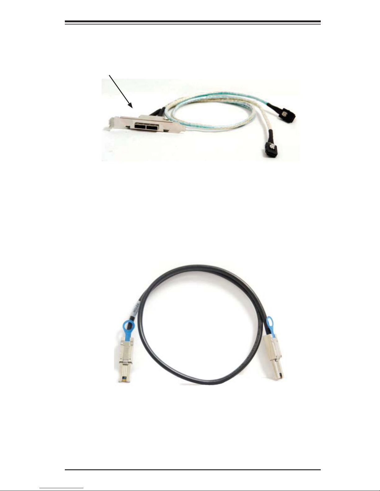
Safety Information and Technical Specifi cations
Dual HBA Confi guration Cables
Dual Port Cable
Assembly
Figure 3-17: Dual Port Internal Cable (CBL-0168L)
Cable Name: SAS Dual-port Cable Assembly, 68/76cm
Part #: CBL-0168L
Placement: Internal cable
Ports: Dual
Description: Internal cascading cable. Connects the backplane to the Host Bus
Adapter (HBA) or external port. Used in dual port environments.
Cable Name: SAS EL2/EL1 Cascading Cable (External), 68cm
Part #: CBL-0166L
Placement: External Cable
Ports: Single or Dual
Description: External cascading cable. Connects ports between servers. Use one
cable for single port connections and two cables for dual port connections.
Figure 3-18: External Cable (CBL-0166L)
3-11
Page 28
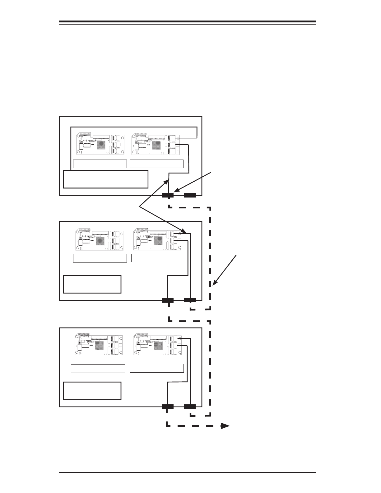
SAS-216EL Backplane User's Guide
MH1
MH2
MH3
MH4
BC1
C340
C341
C342
C343
C344
C345
C326
C327
C334
C335
C336
C337
C338
C339
C346
C347
C348
C349
C350
C351
C103
C105
C106
C107
C111
C113
C118
C120
C123
C124
C126
C127
C129
C130
C132
C133
C135
C138
C146
C153
C155
C157
C158
C159
C162
C166
C168
C172
C178
C88
C90
C94
C98
C261
C76
C171
C78
C73
BC2
C240
C241
C242
C243
C244
C245
C246
C247
C248
C249
C250
C251
C252
C253
L51
L10
L15
L17
L23
L25
L28
L3
L32
L34
L39
L40
L41
L43
L45
L46
L47
L50
L52
L55
L58
L59
L6
L60
L61
L62
L65
L66
L67
L68
L69
L8
R96
R112
R71
R72
R73
R75
R76
R77
R78
R79
R85
R86
R87
R88
R89
R91
R101
R102
R103
R104
R105
R106
R108
R74
R95
RA3
R97
R98
R99
R8
R5
R11
D1
PRI_MODE1
U2
J2
PRI_J3
PRI_J2
PRI_J1
PRI_FLASH1
PRI_SRAM1
PRI_EXP1
1
3
1
2
WWN
BAR CODE
Rev:1.01
BPN-SAS216EL
MH1
MH2
MH3
MH4
BC1
C340
C341
C342
C343
C344
C345
C326
C327
C334
C335
C336
C337
C338
C339
C346
C347
C348
C349
C350
C351
C103
C105
C106
C107
C111
C113
C118
C120
C123
C124
C126
C127
C129
C130
C132
C133
C135
C138
C146
C153
C155
C157
C158
C159
C162
C166
C168
C172
C178
C88
C90
C94
C98
C261
C76
C171
C78
C73
BC2
C240
C241
C242
C243
C244
C245
C246
C247
C248
C249
C250
C251
C252
C253
L51
L10
L15
L17
L23
L25
L28
L3
L32
L34
L39
L40
L41
L43
L45
L46
L47
L50
L52
L55
L58
L59
L6
L60
L61
L62
L65
L66
L67
L68
L69
L8
R96
R112
R71
R72
R73
R75
R76
R77
R78
R79
R85
R86
R87
R88
R89
R91
R101
R102
R103
R104
R105
R106
R108
R74
R95
RA3
R97
R98
R99
R8
R5
R11
D1
PRI_MODE1
U2
J2
PRI_J3
PRI_J2
PRI_J1
PRI_FLASH1
PRI_SRAM1
PRI_EXP1
1
3
1
2
WWN
BAR CODE
Rev:1.01
BPN-SAS216EL
MH1
MH2
MH3
MH4
BC1
C340
C341
C342
C343
C344
C345
C326
C327
C334
C335
C336
C337
C338
C339
C346
C347
C348
C349
C350
C351
C103
C105
C106
C107
C111
C113
C118
C120
C123
C124
C126
C127
C129
C130
C132
C133
C135
C138
C146
C153
C155
C157
C158
C159
C162
C166
C168
C172
C178
C88
C90
C94
C98
C261
C76
C171
C78
C73
BC2
C240
C241
C242
C243
C244
C245
C246
C247
C248
C249
C250
C251
C252
C253
L51
L10
L15
L17
L23
L25
L28
L3
L32
L34
L39
L40
L41
L43
L45
L46
L47
L50
L52
L55
L58
L59
L6
L60
L61
L62
L65
L66
L67
L68
L69
L8
R96
R112
R71
R72
R73
R75
R76
R77
R78
R79
R85
R86
R87
R88
R89
R91
R101
R102
R103
R104
R105
R106
R108
R74
R95
RA3
R97
R98
R99
R8
R5
R11
D1
PRI_MODE1
U2
J2
PRI_J3
PRI_J2
PRI_J1
PRI_FLASH1
PRI_SRAM1
PRI_EXP1
1
3
1
2
WWN
BAR CODE
Rev:1.01
BPN-SAS216EL
MH1
MH2
MH3
MH4
BC1
C340
C341
C342
C343
C344
C345
C326
C327
C334
C335
C336
C337
C338
C339
C346
C347
C348
C349
C350
C351
C103
C105
C106
C107
C111
C113
C118
C120
C123
C124
C126
C127
C129
C130
C132
C133
C135
C138
C146
C153
C155
C157
C158
C159
C162
C166
C168
C172
C178
C88
C90
C94
C98
C261
C76
C171
C78
C73
BC2
C240
C241
C242
C243
C244
C245
C246
C247
C248
C249
C250
C251
C252
C253
L51
L10
L15
L17
L23
L25
L28
L3
L32
L34
L39
L40
L41
L43
L45
L46
L47
L50
L52
L55
L58
L59
L6
L60
L61
L62
L65
L66
L67
L68
L69
L8
R96
R112
R71
R72
R73
R75
R76
R77
R78
R79
R85
R86
R87
R88
R89
R91
R101
R102
R103
R104
R105
R106
R108
R74
R95
RA3
R97
R98
R99
R8
R5
R11
D1
PRI_MODE1
U2
J2
PRI_J3
PRI_J2
PRI_J1
PRI_FLASH1
PRI_SRAM1
PRI_EXP1
1
3
1
2
WWN
BAR CODE
Rev:1.01
BPN-SAS216EL
3-4 Supported Cascading Confi gurations
Cascading allows the system to access data at a faster rate by allowing several
backplanes to share resources to reduce latency time.
The fi rst backplane in a cascaded system requires a motherboard and HBA. Other
servers require a power control card with no motherboard and no HBA. For more
information, see the SC216 Chassis Manual available at www.supermicro.com.
J2
1
2
MH1
C243
C241
C245
C250
C251
C252
R78
R99
R96
R71
R77
R87
R91
R101
R102
R97
R89
R104
C346
C348
C253
C347
C244
C242
R86
R98
R85
R79
R95
R74
D1
C326
BC1
U2
C76
C73
C78
C171
R5
R11
R8
BC2
R112
C178
PRI_FLASH1
MH4
1
3
PRI_MODE1
C118
C120
C124
C127
C153
C168
C113
C94
C98
C106
C129
C132
C172
C111
C90
C107
C130
C88
C103
C105
C123
C126
C133
C135
C138
C146
C155
C157
C158
C159
C162
C166
C240
C249
C246
R103
R76
R72
R75
R88
R105
R106
C338
C339
C349
C337
C340
C327
C261
PRI_SRAM1
WWN
C247
C248
R73
RA3
R108
C350
C351
C341
C342
C343
C344
C345
C334
C335
C336
L6
L8
L10
L15
L17
L23
L25
L28
L32
L34
L41
L43
L47
L51
L40
L3
L39
L45
L46
L50
L52
L55
L58
L59
L60
L61
L62
L65
L66
L67
L68
L69
PRI_EXP1
PRI_J1
Rev:1.01
PRI_J2
BAR CODE
PRI_J3
J2
1
2
MH1
MH2
C243
C241
C245
C250
C251
C252
R78
R99
R96
R71
R77
R87
R91
R101
R102
R97
R89
R104
C339
C346
C348
C253
C347
C244
C242
R86
R98
R85
R79
R95
R74
D1
C326
BC1
U2
C76
C73
C78
C171
R5
R11
R8
BC2
R112
C178
PRI_FLASH1
MH3
MH4
1
3
PRI_MODE1
C118
C120
C124
C127
C153
C168
C113
C94
C98
C106
C129
C132
C172
C111
C90
C107
C130
C88
C103
C105
C123
C126
C133
C135
C138
C146
C155
C157
C158
C159
C162
C166
C240
C249
C246
C247
C248
R103
R73
RA3
R76
R72
R75
R88
R105
R106
R108
C350
C351
C338
C349
C337
C341
C342
C343
C344
C345
C334
C335
C336
L6
L8
L23
L25
L3
L39
L45
L46
L50
L52
L55
L58
L59
L60
L61
L62
L65
L66
L67
L68
L69
C340
C327
PRI_EXP1
Rev:1.01
C261
PRI_SRAM1
MH2
WWN
L10
L15
L17
L28
L32
L34
L41
L43
L47
L51
L40
PRI_J1
PRI_J2
BAR CODE
MH3
PRI_J3
Port B Expander 2
Port A Expander 1
HBA (Host Bus Adapter)
Cable 0167L
(internal cable)
J2
1
2
MH1
C243
C241
C245
C250
C251
C252
R78
R99
R96
R71
R77
R87
R91
R101
R102
R97
R89
C346
C348
C253
C347
C244
C242
R86
R98
R85
R79
R95
R74
D1
C326
BC1
U2
C76
C73
C78
C171
R5
R11
R8
BC2
R112
C178
PRI_FLASH1
MH4
1
3
PRI_MODE1
C118
C120
C124
C127
C153
C168
C113
C94
C98
C106
C129
C132
C172
C111
C90
C107
C130
C88
C103
C105
C123
C126
C133
C135
C138
C146
C155
C157
C158
C159
C162
C166
C240
C249
C246
R103
R76
R72
R88
R104
R105
R106
C338
C339
C337
C340
C327
C261
PRI_SRAM1
WWN
C247
C248
R73
RA3
R75
R108
C350
C351
C349
C341
C342
C343
C344
C345
C334
C335
C336
L6
L8
L10
L15
L17
L23
L25
L28
L32
L34
L41
L43
L47
L51
L40
L3
L39
L45
L46
L50
L52
L55
L58
L59
L60
L61
L62
L65
L66
L67
L68
L69
PRI_EXP1
PRI_J1
Rev:1.01
PRI_J2
BAR CODE
PRI_J3
Port B Expander 2
J2
MH1
MH2
C243
R71
C242
R85
R74
D1
C76
PRI_FLASH1
MH4
MH3
1
3
PRI_MODE1
Port A Expander 1
Power Card
J2
1
2
MH1
C243
C241
C245
C250
C251
C252
R78
R99
R96
R71
R77
R87
R91
R101
R102
R97
R89
C346
C348
C253
C347
C244
C242
R86
R98
R85
R79
R95
R74
D1
C326
BC1
U2
C76
C73
C78
C171
R5
R11
R8
BC2
R112
C178
PRI_FLASH1
MH4
1
3
PRI_MODE1
C118
C120
C124
C127
C153
C168
C113
C94
C98
C106
C129
C132
C172
C111
C90
C107
C130
C88
C103
C105
C123
C126
C133
C135
C138
C146
C155
C157
C158
C159
C162
C166
C240
C249
C246
R103
R76
R72
R88
R104
R105
R106
C338
C339
C337
C340
C327
C261
PRI_SRAM1
WWN
C247
C248
R73
RA3
R75
R108
C350
C351
C349
C341
C342
C343
C344
C345
C334
C335
C336
L6
L8
L10
L15
L17
L23
L25
L28
L32
L34
L41
L43
L47
L51
L40
L3
L39
L45
L46
L50
L52
L55
L58
L59
L60
L61
L62
L65
L66
L67
L68
L69
PRI_EXP1
PRI_J1
Rev:1.01
PRI_J2
BAR CODE
PRI_J3
J2
MH1
MH2
R71
C242
R85
R74
D1
C76
PRI_FLASH1
MH3
MH4
1
3
PRI_MODE1
Single Port Cable
Assembly
1
2
C118
C120
C124
C127
C153
C168
C113
C94
C98
C106
C129
C132
C172
C111
C90
C107
C130
C88
C103
C105
C123
C126
C133
C135
C138
C146
C155
C157
C158
C159
C162
C166
C240
C249
C241
C245
C246
C247
C248
C250
C251
C252
R103
R73
R78
RA3
R99
R96
R77
R87
R91
R101
R102
R97
R76
R72
R75
R88
R89
R104
R105
R106
R108
C350
C351
C338
C339
C346
C349
C337
C348
C253
C347
C244
R86
R98
C341
C342
C343
C344
C345
C334
C335
C336
R79
R95
C243
R97
R79
R95
L6
L8
L23
L25
L3
L39
L45
L46
L50
L52
L55
L58
L59
L60
L61
L62
L65
L66
L67
L68
L69
C326
C340
C327
PRI_EXP1
BC1
U2
C73
C78
C171
R5
R11
R8
BC2
R112
C178
Rev:1.01
C261
PRI_SRAM1
1
2
C153
C168
C113
C94
C129
C132
C172
C111
C90
C107
C88
C123
C126
C135
C138
C146
C155
C157
C158
C159
C162
C166
C240
C249
C241
C245
C246
C247
C248
C250
C251
C252
R103
R73
R78
RA3
R99
R96
R77
R87
R91
R101
R102
R76
R72
R75
R88
R89
R104
R105
R106
R108
C350
C351
C338
C339
C346
C349
C337
C348
C253
C347
C244
R86
R98
C341
C342
C343
C344
C345
C334
C335
C336
L6
L8
L23
L25
L3
L39
L45
L46
L50
L52
L55
L58
L59
L60
L61
L62
L65
L66
L67
L68
L69
C326
C340
C327
PRI_EXP1
BC1
U2
C73
C78
C171
R5
R11
R8
BC2
R112
C178
Rev:1.01
C261
PRI_SRAM1
MH2
WWN
L10
L15
L17
L28
L32
L34
L41
L43
L47
L51
L40
PRI_J1
PRI_J2
BAR CODE
MH3
PRI_J3
C118
C120
C124
C127
C98
C106
C130
C103
C105
C133
MH2
WWN
L10
L15
L17
L28
L32
L34
L41
L43
L47
L51
L40
PRI_J1
PRI_J2
BAR CODE
MH3
PRI_J3
Cable 0166L
(external cable)
Port B Expander 2
Power Card
Figure 3-19: Simple Cascaded Confi guration
Port A Expander 1
3-12
Page 29
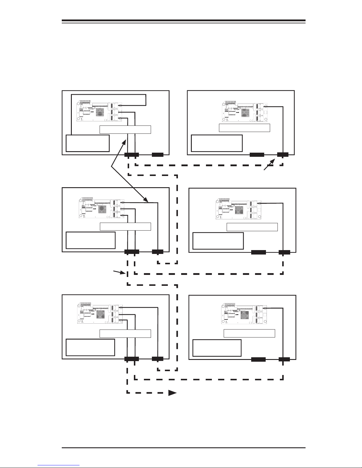
Safety Information and Technical Specifi cations
MH1
MH2
MH3
MH4
BC1
C340
C341
C342
C343
C344
C345
C326
C327
C334
C335
C336
C337
C338
C339
C346
C347
C348
C349
C350
C351
C103
C105
C106
C107
C111
C113
C118
C120
C123
C124
C126
C127
C129
C130
C132
C133
C135
C138
C146
C153
C155
C157
C158
C159
C162
C166
C168
C172
C178
C88
C90
C94
C98
C261
C76
C171
C78
C73
BC2
C240
C241
C242
C243
C244
C245
C246
C247
C248
C249
C250
C251
C252
C253
L51
L10
L15
L17
L23
L25
L28
L3
L32
L34
L39
L40
L41
L43
L45
L46
L47
L50
L52
L55
L58
L59
L6
L60
L61
L62
L65
L66
L67
L68
L69
L8
R96
R112
R71
R72
R73
R75
R76
R77
R78
R79
R85
R86
R87
R88
R89
R91
R101
R102
R103
R104
R105
R106
R108
R74
R95
RA3
R97
R98
R99
R8
R5
R11
D1
PRI_MODE1
U2
J2
PRI_J3
PRI_J2
PRI_J1
PRI_FLASH1
PRI_SRAM1
PRI_EXP1
1
3
1
2
WWN
BAR CODE
Rev:1.01
BPN-SAS216EL
Server System with Single SAS HBA
The expanders allow horizontal branching. This confi guration also applies to dual
ports.
J2
1
2
MH1
C243
C241
C245
C250
C251
C252
R78
R99
R96
R71
R77
R87
R91
R101
R102
R97
R89
R104
C346
C348
C253
C347
C244
C242
R86
R98
R85
R79
R95
R74
D1
C326
BC1
U2
C76
C73
C78
C171
R5
R11
R8
BC2
R112
C178
PRI_FLASH1
MH4
1
3
PRI_MODE1
C118
C120
C124
C127
C153
C168
C113
C94
C98
C106
C129
C132
C172
C111
C90
C107
C130
C88
C103
C105
C123
C126
C133
C135
C138
C146
C155
C157
C158
C159
C162
C166
C240
C249
C246
C247
C248
R103
R73
RA3
R76
R72
R75
R88
R105
R106
R108
C350
C351
C338
C339
C349
C337
C341
C342
C343
C344
C345
C334
C335
C336
L6
L8
L10
L23
L25
L3
L39
L45
L46
L50
L52
L55
L58
L59
L60
L61
L62
L65
L66
L67
L68
L69
C340
C327
PRI_EXP1
Rev:1.01
C261
PRI_SRAM1
MH2
WWN
L15
L17
L28
L32
L34
L41
L43
L47
L51
L40
PRI_J1
PRI_J2
BAR CODE
MH3
PRI_J3
Port A Expander 1
J2
1
2
MH1
C243
C241
C245
C250
C251
C252
R78
R99
R96
R71
R77
R87
R91
R101
R102
R97
R89
C346
C348
C253
C347
C244
C242
R86
R98
R85
R79
R95
R74
D1
C326
BC1
U2
C76
C73
C78
C171
R5
R11
R8
BC2
R112
C178
PRI_FLASH1
MH4
1
3
PRI_MODE1
C118
C120
C124
C127
C153
C168
C113
C94
C98
C106
C129
C132
C172
C111
C90
C107
C130
C88
C103
C105
C123
C126
C133
C135
C138
C146
C155
C157
C158
C159
C162
C166
C240
C249
C246
C248
R103
R76
R72
R75
R88
R104
R105
R106
R108
C338
C339
C349
C337
C340
C327
C261
PRI_SRAM1
WWN
C247
R73
RA3
C350
C351
C341
C342
C343
C344
C345
C334
C335
C336
L6
L8
L10
L15
L17
L23
L25
L28
L32
L34
L41
L43
L47
L51
L40
L3
L39
L45
L46
L50
L52
L55
L58
L59
L60
L61
L62
L65
L66
L67
L68
L69
PRI_EXP1
PRI_J1
Rev:1.01
PRI_J2
BAR CODE
PRI_J3
Port A Expander 1
MH2
MH3
HBA
Cable 0167L
(internal cable)
J2
1
2
MH1
C153
C168
C113
C94
C129
C132
C172
C111
C90
C107
C88
C123
C126
C135
C138
C146
C155
C157
C158
C159
C162
C166
C240
C249
C243
C241
C245
C246
C247
C248
C250
C251
C252
R103
R73
R78
RA3
R99
R96
R71
R77
R87
R91
R101
R102
R97
R76
R72
R75
R88
R89
R104
R105
R106
R108
C350
C351
C338
C339
C346
C349
C337
C348
C253
C347
C244
C242
R86
R98
R85
C341
C342
C343
C344
C345
C334
C335
C336
R79
R95
R74
D1
C76
PRI_FLASH1
MH4
1
3
PRI_MODE1
L6
L8
L10
L23
L25
L28
L3
L39
L45
L46
L50
L52
L55
L58
L59
L60
L61
L62
L65
L66
L67
L68
L69
C326
C340
C327
PRI_EXP1
BC1
U2
C73
C78
C171
R5
R11
R8
BC2
R112
C178
Rev:1.01
C261
PRI_SRAM1
Port A Expander 1
Power Card
Cable 0166L
(external cable)
J2
1
2
MH1
C153
C168
C113
C94
C98
C106
C129
C132
C172
C111
C90
C107
C88
C103
C105
C123
C126
C135
C138
C146
C155
C157
C158
C159
C162
C166
C240
C249
C243
C241
C245
C246
C247
C248
C250
C251
C252
R103
R73
R78
RA3
R99
R96
R71
R77
R87
R91
R101
R102
R97
R76
R72
R75
R88
R89
R104
R105
R106
R108
C350
C351
C338
C339
C346
C349
C337
C348
C253
C347
C244
C242
R86
R98
R85
C341
C342
C343
C344
C345
C334
C335
C336
R79
R95
R74
D1
C76
C78
C178
PRI_FLASH1
MH4
1
3
PRI_MODE1
L6
L8
L10
L15
L17
L23
L25
L28
L32
L3
L39
L45
L46
L50
L52
L55
L58
L59
L60
L61
L62
L65
L66
L67
L68
L69
C326
C340
C327
PRI_EXP1
BC1
U2
C73
C171
R5
R11
R8
BC2
R112
Rev:1.01
C261
PRI_SRAM1
Power Card
Single Port Cable
Assembly
J2
1
C118
C120
C124
C127
C98
C106
C130
C103
C105
C133
MH2
WWN
L15
L17
L32
L34
L41
L43
L47
L51
L40
PRI_J1
PRI_J2
BAR CODE
MH3
PRI_J3
2
MH1
C243
C241
C245
C250
C251
C252
R78
R99
R96
R71
R77
R87
R91
R101
R102
R97
R89
R104
C346
C348
C253
C347
C244
C242
R86
R98
R85
R79
R95
R74
D1
C326
BC1
U2
C76
C73
C78
C171
R5
R11
R8
BC2
R112
C178
PRI_FLASH1
MH4
1
3
PRI_MODE1
C118
C120
C124
C127
C153
C168
C113
C94
C98
C106
C129
C132
C172
C111
C90
C107
C130
C88
C103
C105
C123
C126
C133
C135
C138
C146
C155
C157
C158
C159
C162
C166
C240
C249
C246
C248
R103
R76
R72
R75
R88
R105
R106
R108
C338
C339
C349
C337
C340
C327
C261
PRI_SRAM1
WWN
C247
R73
RA3
C350
C351
C341
C342
C343
C344
C345
C334
C335
C336
L6
L8
L10
L15
L17
L23
L25
L28
L32
L34
L41
L43
L47
L51
L40
L3
L39
L45
L46
L50
L52
L55
L58
L59
L60
L61
L62
L65
L66
L67
L68
L69
PRI_EXP1
PRI_J1
Rev:1.01
PRI_J2
BAR CODE
PRI_J3
Port A Expander 1
MH2
MH3
Power Card
J2
1
2
C118
C120
C124
C127
C130
C133
MH2
WWN
L34
L41
L43
L47
L51
L40
PRI_J1
PRI_J2
BAR CODE
MH3
PRI_J3
MH1
C243
C241
C245
C250
C251
C252
R78
R99
R96
R71
R77
R87
R91
R101
R102
R97
R89
C346
C348
C253
C347
C244
C242
R86
R98
R85
R79
R95
R74
D1
C326
BC1
U2
C76
C73
C78
C171
R5
R11
R8
BC2
R112
C178
PRI_FLASH1
MH4
1
3
PRI_MODE1
C118
C120
C124
C127
C153
C168
C113
C94
C98
C106
C129
C132
C172
C111
C90
C107
C130
C88
C103
C105
C123
C126
C133
C135
C138
C146
C155
C157
C158
C159
C162
C166
C240
C249
C246
C247
C248
R103
R73
RA3
R76
R72
R75
R88
R104
R105
R106
R108
C350
C351
C338
C339
C349
C337
C341
C342
C343
C344
C345
C334
C335
C336
L6
L8
L10
L23
L25
L3
L39
L45
L46
L50
L52
L55
L58
L59
L60
L61
L62
L65
L66
L67
L68
L69
C340
C327
PRI_EXP1
Rev:1.01
C261
PRI_SRAM1
MH2
WWN
L15
L17
L28
L32
L34
L41
L43
L47
L51
L40
PRI_J1
PRI_J2
BAR CODE
MH3
PRI_J3
Port A Expander 1
Power Card
Figure 3-20: Cascaded Confi guration with Horizontal Branching
Port A Expander 1
Power Card
3-13
Page 30

SAS-216EL Backplane User's Guide
MH1
MH2
MH3
MH4
BC1
C340
C341
C342
C343
C344
C345
C326
C327
C334
C335
C336
C337
C338
C339
C346
C347
C348
C349
C350
C351
C103
C105
C106
C107
C111
C113
C118
C120
C123
C124
C126
C127
C129
C130
C132
C133
C135
C138
C146
C153
C155
C157
C158
C159
C162
C166
C168
C172
C178
C88
C90
C94
C98
C261
C76
C171
C78
C73
BC2
C240
C241
C242
C243
C244
C245
C246
C247
C248
C249
C250
C251
C252
C253
L51
L10
L15
L17
L23
L25
L28
L3
L32
L34
L39
L40
L41
L43
L45
L46
L47
L50
L52
L55
L58
L59
L6
L60
L61
L62
L65
L66
L67
L68
L69
L8
R96
R112
R71
R72
R73
R75
R76
R77
R78
R79
R85
R86
R87
R88
R89
R91
R101
R102
R103
R104
R105
R106
R108
R74
R95
RA3
R97
R98
R99
R8
R5
R11
D1
PRI_MODE1
U2
J2
PRI_J3
PRI_J2
PRI_J1
PRI_FLASH1
PRI_SRAM1
PRI_EXP1
1
3
1
2
WWN
BAR CODE
Rev:1.01
BPN-SAS216EL
MH1
MH2
MH3
MH4
BC1
C340
C341
C342
C343
C344
C345
C326
C327
C334
C335
C336
C337
C338
C339
C346
C347
C348
C349
C350
C351
C103
C105
C106
C107
C111
C113
C118
C120
C123
C124
C126
C127
C129
C130
C132
C133
C135
C138
C146
C153
C155
C157
C158
C159
C162
C166
C168
C172
C178
C88
C90
C94
C98
C261
C76
C171
C78
C73
BC2
C240
C241
C242
C243
C244
C245
C246
C247
C248
C249
C250
C251
C252
C253
L51
L10
L15
L17
L23
L25
L28
L3
L32
L34
L39
L40
L41
L43
L45
L46
L47
L50
L52
L55
L58
L59
L6
L60
L61
L62
L65
L66
L67
L68
L69
L8
R96
R112
R71
R72
R73
R75
R76
R77
R78
R79
R85
R86
R87
R88
R89
R91
R101
R102
R103
R104
R105
R106
R108
R74
R95
RA3
R97
R98
R99
R8
R5
R11
D1
PRI_MODE1
U2
J2
PRI_J3
PRI_J2
PRI_J1
PRI_FLASH1
PRI_SRAM1
PRI_EXP1
1
3
1
2
WWN
BAR CODE
Rev:1.01
BPN-SAS216EL
MH1
MH2
MH3
MH4
BC1
C340
C341
C342
C343
C344
C345
C326
C327
C334
C335
C336
C337
C338
C339
C346
C347
C348
C349
C350
C351
C103
C105
C106
C107
C111
C113
C118
C120
C123
C124
C126
C127
C129
C130
C132
C133
C135
C138
C146
C153
C155
C157
C158
C159
C162
C166
C168
C172
C178
C88
C90
C94
C98
C261
C76
C171
C78
C73
BC2
C240
C241
C242
C243
C244
C245
C246
C247
C248
C249
C250
C251
C252
C253
L51
L10
L15
L17
L23
L25
L28
L3
L32
L34
L39
L40
L41
L43
L45
L46
L47
L50
L52
L55
L58
L59
L6
L60
L61
L62
L65
L66
L67
L68
L69
L8
R96
R112
R71
R72
R73
R75
R76
R77
R78
R79
R85
R86
R87
R88
R89
R91
R101
R102
R103
R104
R105
R106
R108
R74
R95
RA3
R97
R98
R99
R8
R5
R11
D1
PRI_MODE1
U2
J2
PRI_J3
PRI_J2
PRI_J1
PRI_FLASH1
PRI_SRAM1
PRI_EXP1
1
3
1
2
WWN
BAR CODE
Rev:1.01
BPN-SAS216EL
MH1
MH2
MH3
MH4
BC1
C340
C341
C342
C343
C344
C345
C326
C327
C334
C335
C336
C337
C338
C339
C346
C347
C348
C349
C350
C351
C103
C105
C106
C107
C111
C113
C118
C120
C123
C124
C126
C127
C129
C130
C132
C133
C135
C138
C146
C153
C155
C157
C158
C159
C162
C166
C168
C172
C178
C88
C90
C94
C98
C261
C76
C171
C78
C73
BC2
C240
C241
C242
C243
C244
C245
C246
C247
C248
C249
C250
C251
C252
C253
L51
L10
L15
L17
L23
L25
L28
L3
L32
L34
L39
L40
L41
L43
L45
L46
L47
L50
L52
L55
L58
L59
L6
L60
L61
L62
L65
L66
L67
L68
L69
L8
R96
R112
R71
R72
R73
R75
R76
R77
R78
R79
R85
R86
R87
R88
R89
R91
R101
R102
R103
R104
R105
R106
R108
R74
R95
RA3
R97
R98
R99
R8
R5
R11
D1
PRI_MODE1
U2
J2
PRI_J3
PRI_J2
PRI_J1
PRI_FLASH1
PRI_SRAM1
PRI_EXP1
1
3
1
2
WWN
BAR CODE
Rev:1.01
BPN-SAS216EL
MH1
MH2
MH3
MH4
BC1
C340
C341
C342
C343
C344
C345
C326
C327
C334
C335
C336
C337
C338
C339
C346
C347
C348
C349
C350
C351
C103
C105
C106
C107
C111
C113
C118
C120
C123
C124
C126
C127
C129
C130
C132
C133
C135
C138
C146
C153
C155
C157
C158
C159
C162
C166
C168
C172
C178
C88
C90
C94
C98
C261
C76
C171
C78
C73
BC2
C240
C241
C242
C243
C244
C245
C246
C247
C248
C249
C250
C251
C252
C253
L51
L10
L15
L17
L23
L25
L28
L3
L32
L34
L39
L40
L41
L43
L45
L46
L47
L50
L52
L55
L58
L59
L6
L60
L61
L62
L65
L66
L67
L68
L69
L8
R96
R112
R71
R72
R73
R75
R76
R77
R78
R79
R85
R86
R87
R88
R89
R91
R101
R102
R103
R104
R105
R106
R108
R74
R95
RA3
R97
R98
R99
R8
R5
R11
D1
PRI_MODE1
U2
J2
PRI_J3
PRI_J2
PRI_J1
PRI_FLASH1
PRI_SRAM1
PRI_EXP1
1
3
1
2
WWN
BAR CODE
Rev:1.01
BPN-SAS216EL
MH1
MH2
MH3
MH4
BC1
C340
C341
C342
C343
C344
C345
C326
C327
C334
C335
C336
C337
C338
C339
C346
C347
C348
C349
C350
C351
C103
C105
C106
C107
C111
C113
C118
C120
C123
C124
C126
C127
C129
C130
C132
C133
C135
C138
C146
C153
C155
C157
C158
C159
C162
C166
C168
C172
C178
C88
C90
C94
C98
C261
C76
C171
C78
C73
BC2
C240
C241
C242
C243
C244
C245
C246
C247
C248
C249
C250
C251
C252
C253
L51
L10
L15
L17
L23
L25
L28
L3
L32
L34
L39
L40
L41
L43
L45
L46
L47
L50
L52
L55
L58
L59
L6
L60
L61
L62
L65
L66
L67
L68
L69
L8
R96
R112
R71
R72
R73
R75
R76
R77
R78
R79
R85
R86
R87
R88
R89
R91
R101
R102
R103
R104
R105
R106
R108
R74
R95
RA3
R97
R98
R99
R8
R5
R11
D1
PRI_MODE1
U2
J2
PRI_J3
PRI_J2
PRI_J1
PRI_FLASH1
PRI_SRAM1
PRI_EXP1
1
3
1
2
WWN
BAR CODE
Rev:1.01
BPN-SAS216EL
Dual SAS HBA and Cascaded Confi guration
J2
1
2
MH1
C243
C241
C245
C250
C251
C252
R78
R99
R96
R71
R77
R87
R91
R101
R102
R97
R89
R104
C346
C348
C253
C347
C244
C242
R86
R98
R85
R79
R95
R74
D1
C326
BC1
U2
C76
C73
C78
C171
R5
R11
R8
BC2
R112
C178
PRI_FLASH1
MH4
1
3
PRI_MODE1
C118
C120
C124
C127
C153
C168
C113
C94
C98
C106
C129
C132
C172
C111
C90
C107
C130
C88
C103
C105
C123
C126
C133
C135
C138
C146
C155
C157
C158
C159
C162
C166
C240
C249
C246
R103
R76
R72
R75
R88
R105
R106
C338
C339
C349
C337
C340
C327
C261
PRI_SRAM1
WWN
C247
C248
R73
RA3
R108
C350
C351
C341
C342
C343
C344
C345
C334
C335
C336
L6
L8
L10
L15
L17
L23
L25
L28
L32
L34
L41
L43
L47
L51
L40
L3
L39
L45
L46
L50
L52
L55
L58
L59
L60
L61
L62
L65
L66
L67
L68
L69
PRI_EXP1
Rev:1.01
BAR CODE
Port B Expander 2
HBA
HBA
Cable 0168L
(internal cable)
J2
1
2
MH1
C243
C241
C245
C250
C251
C252
R78
R99
R96
R71
R77
R87
R91
R101
R102
R97
R89
C346
C348
C253
C347
C244
C242
R86
R98
R85
R79
R95
R74
D1
C326
BC1
U2
C76
C73
C78
C171
R5
R11
R8
BC2
R112
C178
PRI_FLASH1
MH4
1
3
PRI_MODE1
Port B Expander 2
C118
C120
C124
C127
C153
C168
C113
C94
C98
C106
C129
C132
C172
C111
C90
C107
C130
C88
C103
C105
C123
C126
C133
C135
C138
C146
C155
C157
C158
C159
C162
C166
C240
C249
C246
C247
C248
R103
R73
RA3
R76
R72
R75
R88
R104
R105
R106
R108
C350
C351
C338
C339
C349
C337
C341
C342
C343
C344
C345
C334
C335
C336
L6
L8
L23
L25
L3
L39
L45
L46
L50
L52
L55
L58
L59
L60
L61
L62
L65
L66
L67
L68
L69
C340
C327
PRI_EXP1
Rev:1.01
C261
PRI_SRAM1
MH2
WWN
L10
L15
L17
L28
L32
L34
L41
L43
L47
L51
L40
PRI_J1
PRI_J2
BAR CODE
MH3
PRI_J3
MH2
PRI_J1
PRI_J2
MH3
PRI_J3
C243
C241
C252
R78
R99
R96
R71
R91
R97
C253
C244
C242
R86
R98
R85
R79
R95
R74
D1
U2
C76
C73
C78
R11
R112
C178
PRI_FLASH1
MH4
1
3
PRI_MODE1
J2
MH1
Port A Expander 1
J2
1
2
MH1
C153
C168
C129
C132
C172
C107
C88
C123
C126
C135
C138
C146
C155
C157
C158
C159
C162
C166
C240
C249
C243
C241
C245
C246
C247
C248
C250
C251
C252
R103
R73
R78
RA3
R99
R96
R71
R77
R87
R91
R101
R102
R97
R76
R72
R75
R88
R89
R104
R105
R106
R108
C350
C351
C338
C339
C346
C349
C337
C348
C253
C347
C244
C242
R86
R98
R85
C341
C342
C343
C344
C345
C334
C335
C336
R79
R95
R74
D1
C76
PRI_FLASH1
MH4
1
3
PRI_MODE1
L6
L3
L39
L45
L46
L50
L52
L55
L58
L59
L60
L61
L62
L65
L66
L67
L68
L69
C326
C340
C327
BC1
U2
C73
C78
C171
R5
R11
R8
BC2
R112
C178
Rev:1.01
C261
PRI_SRAM1
Port A Expander 1
1
2
C118
C120
C124
C127
C153
C168
C113
C94
C98
C106
C129
C132
C172
C111
C90
C107
C130
C88
C103
C105
C123
C126
C133
C135
C138
C146
C155
C157
C158
C159
C162
C166
C240
C249
C245
C246
C247
C248
C250
C251
R103
R73
RA3
R77
R87
R101
R102
R76
R72
R75
R88
R89
R104
R105
R106
R108
C350
C351
C338
C339
C346
C349
C337
C348
C347
C341
C342
C343
C344
C345
C334
C335
C336
L6
L8
L10
L23
L25
L3
L39
L45
L46
L50
L52
L55
L58
L59
L60
L61
L62
L65
L66
L67
L68
L69
C326
C340
C327
PRI_EXP1
BC1
C171
R5
R8
BC2
Rev:1.01
C261
PRI_SRAM1
MH2
WWN
L15
L17
L28
L32
L34
L41
L43
L47
L51
L40
PRI_J1
PRI_J2
BAR CODE
MH3
PRI_J3
Dual Port Cable
Assembly
C118
C120
C124
C127
C113
C94
C98
C106
C111
C90
C130
C103
C105
C133
MH2
WWN
L8
L10
L15
L17
L23
L25
L28
L32
L34
L41
L43
L47
L51
L40
PRI_EXP1
PRI_J1
PRI_J2
BAR CODE
MH3
PRI_J3
Cable 0166L
(external cables)
Power Card
J2
1
2
MH1
C243
C241
C245
C251
C252
R78
R99
R96
R71
R77
R87
R91
R101
R102
R97
R89
C346
C348
C253
C347
C244
C242
R86
R98
R85
R79
R95
R74
D1
C326
BC1
U2
C76
C73
C78
C171
R5
R11
R8
BC2
R112
C178
PRI_FLASH1
MH4
1
3
PRI_MODE1
C118
C120
C124
C127
C153
C168
C113
C94
C98
C106
C129
C132
C172
C111
C90
C107
C130
C88
C103
C105
C123
C126
C133
C135
C138
C146
C155
C157
C158
C159
C162
C166
C240
C249
C246
C247
C248
C250
R103
R73
RA3
R76
R72
R75
R88
R104
R105
R106
R108
C350
C351
C338
C339
C349
C337
C341
C342
C343
C344
C345
C334
C335
C336
L6
L8
L23
L25
L3
L39
L45
L46
L50
L52
L55
L58
L59
L60
L61
L62
L65
L66
L67
L68
L69
C340
C327
PRI_EXP1
Rev:1.01
C261
PRI_SRAM1
MH2
WWN
L10
L15
L17
L28
L32
L34
L41
L43
L47
L51
L40
PRI_J1
PRI_J2
BAR CODE
MH3
PRI_J3
Port B Expander 2
Power Card
Figure 3-21: Dual SAS HBA with Cascaded Confi guration
J2
1
2
MH1
C243
C241
C245
C250
C251
C252
R78
R99
R96
R71
R77
R87
R91
R101
R102
R97
R89
C346
C348
C253
C347
C244
C242
R86
R98
R85
R79
R95
R74
D1
C326
BC1
U2
C76
C73
C78
C171
R5
R11
R8
BC2
R112
C178
PRI_FLASH1
MH4
1
3
PRI_MODE1
C118
C120
C124
C127
C153
C168
C113
C94
C98
C106
C129
C132
C172
C111
C90
C107
C130
C88
C103
C105
C123
C126
C133
C135
C138
C146
C155
C157
C158
C159
C162
C166
C240
C249
C246
C247
C248
R103
R73
RA3
R76
R72
R75
R88
R104
R105
R106
R108
C350
C351
C338
C339
C349
C337
C341
C342
C343
C344
C345
C334
C335
C336
L6
L8
L23
L25
L3
L39
L45
L46
L50
L52
L55
L58
L59
L60
L61
L62
L65
L66
L67
L68
L69
C340
C327
PRI_EXP1
Rev:1.01
C261
PRI_SRAM1
MH2
WWN
L10
L15
L17
L28
L32
L34
L41
L43
L47
L51
L40
PRI_J1
PRI_J2
BAR CODE
MH3
PRI_J3
Port A Expander 1
3-14
Page 31

Safety Information and Technical Specifi cations
MH1
MH2
MH3
MH4
BC1
C340
C341
C342
C343
C344
C345
C326
C327
C334
C335
C336
C337
C338
C339
C346
C347
C348
C349
C350
C351
C103
C105
C106
C107
C111
C113
C118
C120
C123
C124
C126
C127
C129
C130
C132
C133
C135
C138
C146
C153
C155
C157
C158
C159
C162
C166
C168
C172
C178
C88
C90
C94
C98
C261
C76
C171
C78
C73
BC2
C240
C241
C242
C243
C244
C245
C246
C247
C248
C249
C250
C251
C252
C253
L51
L10
L15
L17
L23
L25
L28
L3
L32
L34
L39
L40
L41
L43
L45
L46
L47
L50
L52
L55
L58
L59
L6
L60
L61
L62
L65
L66
L67
L68
L69
L8
R96
R112
R71
R72
R73
R75
R76
R77
R78
R79
R85
R86
R87
R88
R89
R91
R101
R102
R103
R104
R105
R106
R108
R74
R95
RA3
R97
R98
R99
R8
R5
R11
D1
PRI_MODE1
U2
J2
PRI_J3
PRI_J2
PRI_J1
PRI_FLASH1
PRI_SRAM1
PRI_EXP1
1
3
1
2
WWN
BAR CODE
Rev:1.01
BPN-SAS216EL
MH1
MH2
MH3
MH4
BC1
C340
C341
C342
C343
C344
C345
C326
C327
C334
C335
C336
C337
C338
C339
C346
C347
C348
C349
C350
C351
C103
C105
C106
C107
C111
C113
C118
C120
C123
C124
C126
C127
C129
C130
C132
C133
C135
C138
C146
C153
C155
C157
C158
C159
C162
C166
C168
C172
C178
C88
C90
C94
C98
C261
C76
C171
C78
C73
BC2
C240
C241
C242
C243
C244
C245
C246
C247
C248
C249
C250
C251
C252
C253
L51
L10
L15
L17
L23
L25
L28
L3
L32
L34
L39
L40
L41
L43
L45
L46
L47
L50
L52
L55
L58
L59
L6
L60
L61
L62
L65
L66
L67
L68
L69
L8
R96
R112
R71
R72
R73
R75
R76
R77
R78
R79
R85
R86
R87
R88
R89
R91
R101
R102
R103
R104
R105
R106
R108
R74
R95
RA3
R97
R98
R99
R8
R5
R11
D1
PRI_MODE1
U2
J2
PRI_J3
PRI_J2
PRI_J1
PRI_FLASH1
PRI_SRAM1
PRI_EXP1
1
3
1
2
WWN
BAR CODE
Rev:1.01
BPN-SAS216EL
MH1
MH2
MH3
MH4
BC1
C340
C341
C342
C343
C344
C345
C326
C327
C334
C335
C336
C337
C338
C339
C346
C347
C348
C349
C350
C351
C103
C105
C106
C107
C111
C113
C118
C120
C123
C124
C126
C127
C129
C130
C132
C133
C135
C138
C146
C153
C155
C157
C158
C159
C162
C166
C168
C172
C178
C88
C90
C94
C98
C261
C76
C171
C78
C73
BC2
C240
C241
C242
C243
C244
C245
C246
C247
C248
C249
C250
C251
C252
C253
L51
L10
L15
L17
L23
L25
L28
L3
L32
L34
L39
L40
L41
L43
L45
L46
L47
L50
L52
L55
L58
L59
L6
L60
L61
L62
L65
L66
L67
L68
L69
L8
R96
R112
R71
R72
R73
R75
R76
R77
R78
R79
R85
R86
R87
R88
R89
R91
R101
R102
R103
R104
R105
R106
R108
R74
R95
RA3
R97
R98
R99
R8
R5
R11
D1
PRI_MODE1
U2
J2
PRI_J3
PRI_J2
PRI_J1
PRI_FLASH1
PRI_SRAM1
PRI_EXP1
1
3
1
2
WWN
BAR CODE
Rev:1.01
BPN-SAS216EL
MH1
MH2
MH3
MH4
BC1
C340
C341
C342
C343
C344
C345
C326
C327
C334
C335
C336
C337
C338
C339
C346
C347
C348
C349
C350
C351
C103
C105
C106
C107
C111
C113
C118
C120
C123
C124
C126
C127
C129
C130
C132
C133
C135
C138
C146
C153
C155
C157
C158
C159
C162
C166
C168
C172
C178
C88
C90
C94
C98
C261
C76
C171
C78
C73
BC2
C240
C241
C242
C243
C244
C245
C246
C247
C248
C249
C250
C251
C252
C253
L51
L10
L15
L17
L23
L25
L28
L3
L32
L34
L39
L40
L41
L43
L45
L46
L47
L50
L52
L55
L58
L59
L6
L60
L61
L62
L65
L66
L67
L68
L69
L8
R96
R112
R71
R72
R73
R75
R76
R77
R78
R79
R85
R86
R87
R88
R89
R91
R101
R102
R103
R104
R105
R106
R108
R74
R95
RA3
R97
R98
R99
R8
R5
R11
D1
PRI_MODE1
U2
J2
PRI_J3
PRI_J2
PRI_J1
PRI_FLASH1
PRI_SRAM1
PRI_EXP1
1
3
1
2
WWN
BAR CODE
Rev:1.01
BPN-SAS216EL
MH1
MH2
MH3
MH4
BC1
C340
C341
C342
C343
C344
C345
C326
C327
C334
C335
C336
C337
C338
C339
C346
C347
C348
C349
C350
C351
C103
C105
C106
C107
C111
C113
C118
C120
C123
C124
C126
C127
C129
C130
C132
C133
C135
C138
C146
C153
C155
C157
C158
C159
C162
C166
C168
C172
C178
C88
C90
C94
C98
C261
C76
C171
C78
C73
BC2
C240
C241
C242
C243
C244
C245
C246
C247
C248
C249
C250
C251
C252
C253
L51
L10
L15
L17
L23
L25
L28
L3
L32
L34
L39
L40
L41
L43
L45
L46
L47
L50
L52
L55
L58
L59
L6
L60
L61
L62
L65
L66
L67
L68
L69
L8
R96
R112
R71
R72
R73
R75
R76
R77
R78
R79
R85
R86
R87
R88
R89
R91
R101
R102
R103
R104
R105
R106
R108
R74
R95
RA3
R97
R98
R99
R8
R5
R11
D1
PRI_MODE1
U2
J2
PRI_J3
PRI_J2
PRI_J1
PRI_FLASH1
PRI_SRAM1
PRI_EXP1
1
3
1
2
WWN
BAR CODE
Rev:1.01
BPN-SAS216EL
MH1
MH2
MH3
MH4
BC1
C340
C341
C342
C343
C344
C345
C326
C327
C334
C335
C336
C337
C338
C339
C346
C347
C348
C349
C350
C351
C103
C105
C106
C107
C111
C113
C118
C120
C123
C124
C126
C127
C129
C130
C132
C133
C135
C138
C146
C153
C155
C157
C158
C159
C162
C166
C168
C172
C178
C88
C90
C94
C98
C261
C76
C171
C78
C73
BC2
C240
C241
C242
C243
C244
C245
C246
C247
C248
C249
C250
C251
C252
C253
L51
L10
L15
L17
L23
L25
L28
L3
L32
L34
L39
L40
L41
L43
L45
L46
L47
L50
L52
L55
L58
L59
L6
L60
L61
L62
L65
L66
L67
L68
L69
L8
R96
R112
R71
R72
R73
R75
R76
R77
R78
R79
R85
R86
R87
R88
R89
R91
R101
R102
R103
R104
R105
R106
R108
R74
R95
RA3
R97
R98
R99
R8
R5
R11
D1
PRI_MODE1
U2
J2
PRI_J3
PRI_J2
PRI_J1
PRI_FLASH1
PRI_SRAM1
PRI_EXP1
1
3
1
2
WWN
BAR CODE
Rev:1.01
BPN-SAS216EL
Dual SAS HBA and Cascaded Confi guration with
Branching
J2
MH1
C240
C249
C243
C241
C245
C250
C251
C252
R103
R78
R99
R96
R71
R77
R87
R91
R101
R102
R97
R76
R72
R89
R104
R106
C338
C339
C346
C348
C253
C347
C244
C242
R86
R98
R85
R79
R95
R74
D1
C326
C340
C327
BC1
U2
C76
C73
C78
C171
R5
R11
R8
BC2
R112
C178
PRI_FLASH1
MH4
1
3
PRI_MODE1
Port B Ex. 2
HBA
HBA
J2
1
2
MH1
C243
R71
R97
C253
C242
R85
R79
R95
R74
D1
C76
PRI_FLASH1
MH4
1
3
PRI_MODE1
Port B Ex. 2
C118
C120
C124
C127
C153
C168
C113
C94
C98
C106
C129
C132
C172
C111
C90
C107
C130
C88
C103
C105
C123
C126
C133
C135
C138
C146
C155
C157
C158
C159
C162
C166
C240
C249
C241
C245
C246
C247
C248
C250
C251
C252
R103
R73
R78
RA3
R99
R96
R77
R87
R91
R101
R102
R76
R72
R75
R88
R89
R104
R105
R106
R108
C350
C351
C338
C339
C346
C349
C337
C348
C347
C244
R86
R98
C341
C342
C343
C344
C345
C334
C335
C336
L6
L8
L10
L15
L17
L23
L25
L28
L32
L34
L41
L43
L47
L51
L40
L3
L39
L45
L46
L50
L52
L55
L58
L59
L60
L61
L62
L65
L66
L67
L68
L69
C326
C340
C327
PRI_EXP1
BC1
U2
C73
C78
C171
R5
R11
R8
BC2
R112
C178
Rev:1.01
C261
PRI_SRAM1
1
2
C118
C120
C124
C127
C153
C168
C113
C94
C98
C106
C129
C132
C172
C111
C90
C107
C130
C88
C103
C105
C123
C126
C133
C135
C138
C146
C155
C157
C158
C159
C162
C166
WWN
C246
C247
C248
R73
RA3
R75
R88
R105
R108
C350
C351
C349
C337
C341
C342
C343
C344
C345
C334
C335
C336
L6
L8
L10
L15
L17
L23
L25
L28
L32
L34
L41
L43
L47
L51
L40
L3
L39
L45
L46
L50
L52
L55
L58
L59
L60
L61
L62
L65
L66
L67
L68
L69
PRI_EXP1
Rev:1.01
C261
PRI_SRAM1
BAR CODE
MH2
PRI_J1
PRI_J2
MH3
PRI_J3
J2
1
2
MH1
C243
R71
R97
C253
C242
R85
R79
R95
R74
D1
C76
C78
PRI_FLASH1
MH4
1
3
PRI_MODE1
C118
C120
C124
C127
C153
C168
C113
C94
C98
C106
C129
C132
C172
C111
C90
C107
C130
C88
C103
C105
C123
C126
C133
C135
C138
C146
C155
C157
C158
C159
C162
C166
C240
C249
C241
C245
C251
C252
R78
R99
R96
R77
R87
R91
R102
C348
C347
C244
R86
R98
BC1
U2
C73
C171
R5
R11
R8
BC2
R112
C178
WWN
C246
C247
C248
C250
R103
R73
RA3
R101
R76
R72
R75
R88
R89
R104
R105
R106
R108
C350
C351
C338
C339
C346
C349
C337
C341
C342
C343
C344
C345
C334
C335
C336
L6
L8
L10
L15
L17
L23
L25
L28
L32
L34
L41
L43
L47
L51
L40
L3
L39
L45
L46
L50
L52
L55
L58
L59
L60
L61
L62
L65
L66
L67
L68
L69
C326
C340
C327
PRI_EXP1
PRI_J1
PRI_J2
Rev:1.01
C261
PRI_SRAM1
BAR CODE
PRI_J3
Port A Ex. 1
MH2
MH3
J2
1
2
MH1
C243
R71
R97
C253
C242
R85
R79
R95
R74
D1
C76
PRI_FLASH1
MH4
1
3
PRI_MODE1
C118
C120
C124
C127
C153
C168
C113
C94
C98
C106
C129
C132
C172
C111
C90
C107
C130
C88
C103
C105
C123
C126
C133
C135
C138
C146
C155
C157
C158
C159
C162
C166
C240
C249
C241
C245
C246
C247
C248
C250
C251
C252
R103
R73
R78
RA3
R99
R96
R77
R87
R91
R101
R102
R76
R72
R75
R88
R89
R104
R105
R106
R108
C350
C351
C338
C339
C346
C349
C337
C348
C347
C244
R86
R98
C341
C342
C343
C344
C345
C334
C335
C336
L6
L8
L10
L15
L17
L23
L25
L28
L32
L34
L41
L43
L47
L51
L40
L3
L39
L45
L46
L50
L52
L55
L58
L59
L60
L61
L62
L65
L66
L67
L68
L69
C326
C340
C327
PRI_EXP1
BC1
U2
C73
C78
C171
R5
R11
R8
BC2
R112
C178
Rev:1.01
C261
PRI_SRAM1
Port B Ex. 2
MH2
WWN
PRI_J1
PRI_J2
BAR CODE
MH3
PRI_J3
J2
1
2
MH1
C243
R71
R97
C253
C242
R85
R79
R95
R74
D1
C76
PRI_FLASH1
MH4
1
3
PRI_MODE1
C118
C120
C124
C127
C153
C168
C113
C94
C98
C106
C129
C132
C172
C111
C90
C107
C130
C88
C103
C105
C123
C126
C133
C135
C138
C146
C155
C157
C158
C159
C162
C166
C240
C249
C241
C245
C251
C252
R78
R99
R96
R77
R87
R91
R102
C348
C347
C244
R86
R98
BC1
U2
C73
C78
C171
R5
R11
R8
BC2
R112
C178
WWN
C246
C247
C248
C250
R103
R73
RA3
R101
R76
R72
R75
R88
R89
R104
R105
R106
R108
C350
C351
C338
C339
C346
C349
C337
C341
C342
C343
C344
C345
C334
C335
C336
L6
L8
L10
L15
L17
L23
L25
L28
L32
L34
L41
L43
L47
L51
L40
L3
L39
L45
L46
L50
L52
L55
L58
L59
L60
L61
L62
L65
L66
L67
L68
L69
C326
C340
C327
PRI_EXP1
PRI_J1
PRI_J2
Rev:1.01
C261
PRI_SRAM1
BAR CODE
PRI_J3
Port A Ex. 1
MH2
MH3
Power
Card
J2
1
2
MH1
WWN
C243
R71
R97
C253
C242
R85
R79
R95
R74
D1
C76
PRI_J1
PRI_J2
BAR CODE
PRI_FLASH1
MH4
1
3
PRI_MODE1
PRI_J3
C118
C120
C124
C127
C153
C168
C113
C94
C98
C106
C129
C132
C172
C111
C90
C107
C130
C88
C103
C105
C123
C126
C133
C135
C138
C146
C155
C157
C158
C159
C162
C166
C240
C249
C241
C245
C252
R78
R99
R96
R77
R87
R91
R102
C348
C347
C244
R86
R98
BC1
U2
C73
C78
C171
R5
R11
R8
BC2
R112
C178
WWN
C246
C247
C248
C250
C251
R103
R73
RA3
R101
R76
R72
R75
R88
R89
R104
R105
R106
R108
C350
C351
C338
C339
C346
C349
C337
C341
C342
C343
C344
C345
C334
C335
C336
L6
L8
L10
L15
L17
L23
L25
L28
L32
L34
L41
L43
L47
L51
L40
L3
L39
L45
L46
L50
L52
L55
L58
L59
L60
L61
L62
L65
L66
L67
L68
L69
C326
C340
C327
PRI_EXP1
PRI_J1
PRI_J2
Rev:1.01
C261
PRI_SRAM1
BAR CODE
PRI_J3
Port A Ex. 1
MH2
MH3
J2
1
2
MH1
C243
R71
R91
R97
C253
C242
R85
R79
R95
R74
D1
C76
C78
PRI_FLASH1
MH4
1
3
PRI_MODE1
C118
C120
C124
C127
C153
C168
C113
C94
C98
C106
C129
C132
C172
C111
C90
C107
C130
C88
C103
C105
C123
C126
C133
C135
C138
C146
C155
C157
C158
C159
C162
C166
C240
C249
C241
C245
C251
C252
R78
R99
R96
R77
R87
R101
R102
C348
C347
C244
R86
R98
BC1
U2
C73
C171
R5
R11
R8
BC2
R112
C178
WWN
C246
C247
C248
C250
R103
R73
RA3
R76
R72
R75
R88
R89
R104
R105
R106
R108
C350
C351
C338
C339
C346
C349
C337
C341
C342
C343
C344
C345
C334
C335
C336
L6
L8
L10
L15
L17
L23
L25
L28
L32
L34
L41
L43
L47
L51
L40
L3
L39
L45
L46
L50
L52
L55
L58
L59
L60
L61
L62
L65
L66
L67
L68
L69
C326
C340
C327
PRI_EXP1
Rev:1.01
C261
PRI_SRAM1
BAR CODE
Port B Ex. 2
MH2
PRI_J1
PRI_J2
MH3
PRI_J3
J2
1
2
MH1
C243
R71
R91
R97
C253
C242
R85
R79
R95
R74
D1
C76
C78
PRI_FLASH1
MH4
1
3
PRI_MODE1
C118
C120
C124
C127
C153
C168
C113
C94
C98
C106
C129
C132
C172
C111
C90
C107
C130
C88
C103
C105
C123
C126
C133
C135
C138
C146
C155
C157
C158
C159
C162
C166
C240
C249
C241
C245
C251
C252
R78
R99
R96
R77
R87
R101
R102
R89
C346
C348
C347
C244
R86
R98
BC1
U2
C73
C171
R5
R11
R8
BC2
R112
C178
WWN
C246
C247
C248
C250
R103
R73
RA3
R76
R72
R75
R88
R104
R105
R106
R108
C350
C351
C338
C339
C349
C337
C341
C342
C343
C344
C345
C334
C335
C336
L6
L8
L10
L15
L17
L23
L25
L28
L32
L34
L41
L43
L47
L51
L40
L3
L39
L45
L46
L50
L52
L55
L58
L59
L60
L61
L62
L65
L66
L67
L68
L69
C326
C340
C327
PRI_EXP1
PRI_J1
PRI_J2
Rev:1.01
C261
PRI_SRAM1
BAR CODE
PRI_J3
Port A Ex. 1
MH2
MH3
Power
Card
J2
1
2
MH1
C243
R71
R97
C253
C242
R85
R79
R95
R74
D1
C76
PRI_FLASH1
MH4
1
3
PRI_MODE1
C118
C120
C124
C127
C153
C168
C113
C94
C98
C106
C129
C132
C172
C111
C90
C107
C130
C88
C103
C105
C123
C126
C133
C135
C138
C146
C155
C157
C158
C159
C162
C166
C240
C249
C241
C245
C251
C252
R78
R99
R96
R77
R87
R91
R101
R102
C348
C347
C244
R86
R98
BC1
U2
C73
C78
C171
R5
R11
R8
BC2
R112
C178
WWN
C246
C247
C248
C250
R103
R73
RA3
R76
R72
R75
R88
R89
R104
R105
R106
R108
C350
C351
C338
C339
C346
C349
C337
C341
C342
C343
C344
C345
C334
C335
C336
L6
L8
L10
L15
L17
L23
L25
L28
L32
L34
L41
L43
L47
L51
L40
L3
L39
L45
L46
L50
L52
L55
L58
L59
L60
L61
L62
L65
L66
L67
L68
L69
C326
C340
C327
PRI_EXP1
Rev:1.01
C261
PRI_SRAM1
BAR CODE
Port B Ex. 2
Power
Card
MH2
PRI_J1
PRI_J2
MH3
PRI_J3
J2
1
2
MH1
C243
R71
R97
C253
C242
R85
R79
R95
R74
D1
C76
PRI_FLASH1
MH4
1
3
PRI_MODE1
C118
C120
C124
C127
C153
C168
C113
C94
C98
C106
C129
C132
C172
C111
C90
C107
C130
C88
C103
C105
C123
C126
C133
C135
C138
C146
C155
C157
C158
C159
C162
C166
C240
C249
C241
C245
C251
C252
R78
R99
R96
R77
R87
R91
R101
R102
R89
C346
C348
C347
C244
R86
R98
BC1
U2
C73
C78
C171
R5
R11
R8
BC2
R112
C178
WWN
C246
C247
C248
C250
R103
R73
RA3
R76
R72
R75
R88
R104
R105
R106
R108
C350
C351
C338
C339
C349
C337
C341
C342
C343
C344
C345
C334
C335
C336
L6
L8
L10
L15
L17
L23
L25
L28
L32
L34
L41
L43
L47
L51
L40
L3
L39
L45
L46
L50
L52
L55
L58
L59
L60
L61
L62
L65
L66
L67
L68
L69
C326
C340
C327
PRI_EXP1
Rev:1.01
C261
PRI_SRAM1
BAR CODE
Port A Ex. 1
Power
Card
Cable 0166L
(external cable)
MH2
PRI_J1
PRI_J2
MH3
PRI_J3
J2
1
2
MH1
C243
R71
R97
C242
R85
R79
R74
D1
C76
PRI_FLASH1
MH4
1
3
PRI_MODE1
C118
C120
C124
C127
C153
C168
C113
C94
C98
C106
C129
C132
C172
C111
C90
C107
C130
C88
C103
C105
C123
C126
C133
C135
C138
C146
C155
C157
C158
C159
C162
C166
C240
C249
C241
C245
C251
C252
R78
R99
R96
R77
R87
R91
R101
R102
C348
C253
C347
C244
R86
R98
R95
BC1
U2
C73
C78
C171
R5
R11
R8
BC2
R112
C178
WWN
C246
C247
C248
C250
R103
R73
RA3
R76
R72
R75
R88
R89
R104
R105
R106
R108
C350
C351
C338
C339
C346
C349
C337
C341
C342
C343
C344
C345
C334
C335
C336
L6
L8
L10
L15
L17
L23
L25
L28
L32
L34
L41
L43
L47
L51
L40
L3
L39
L45
L46
L50
L52
L55
L58
L59
L60
L61
L62
L65
L66
L67
L68
L69
C326
C340
C327
PRI_EXP1
PRI_J1
PRI_J2
Rev:1.01
C261
PRI_SRAM1
BAR CODE
PRI_J3
Port B Ex. 2
J2
1
2
MH1
C153
C168
C172
C155
C157
C158
MH2
MH3
C159
C240
C249
C243
C241
C245
C246
C247
C248
C250
C251
C252
R103
R73
R78
RA3
R99
R96
R71
R77
R87
R91
R101
R102
R97
R76
R72
R75
R88
R89
R104
R105
R106
R108
C350
C351
C338
C339
C346
C349
C337
C348
C253
C347
C244
C242
R86
R98
R85
C341
C342
C343
C344
C345
C334
C335
C336
R79
R95
R74
D1
L59
L66
C326
C340
C327
BC1
U2
C76
C73
C78
C171
R5
R11
R8
BC2
R112
C178
Rev:1.01
C261
PRI_SRAM1
PRI_FLASH1
MH4
1
3
PRI_MODE1
Port A Ex. 1
C118
C120
C124
C127
C113
C94
C98
C106
C129
C132
C111
C90
C107
C130
C88
C103
C105
C123
C126
C133
C135
C138
C146
C162
C166
MH2
WWN
L6
L8
L10
L15
L17
L23
L25
L28
L32
L34
L41
L43
L47
L51
L40
L3
L39
L45
L46
L50
L52
L55
L58
L60
L61
L62
L65
L67
L68
L69
PRI_EXP1
PRI_J1
PRI_J2
BAR CODE
MH3
PRI_J3
Power
Card
Figure 3-22: Dual SAS HBA with Cascaded Confi guration and
Branching
3-15
Page 32

SAS-216EL Backplane User's Guide
The products sold by Supermicro are not intended for and will not be used in life support systems, medical equipment, nuclear facilities or systems, aircraft, aircraft devices,
aircraft/emergency communication devices or other critical systems whose failure to perform be reasonably expected to result in signifi cant injury or loss of life or catastrophic
property damage. Accordingly, Supermicro disclaims any and all liability, and should
buyer use or sell such products for use in such ultra-hazardous applications, it does so
entirely at its own risk. Furthermore, buyer agrees to fully indemnify, defend and hold
Supermicro harmless for and against any and all claims, demands, actions, litigation,
and proceedings of any kind arising out of or related to such ultra-hazardous use or
sale.
Disclaimer (cont.)
3-16
 Loading...