

Page 1

SUPER
®
M35TQ
Mobile Rack
USER'S GUIDE
Rev. 1.0c
Page 2

M35TQ Mobile Rack User's Guide
The information in this User’s Manual has been carefully reviewed and is believed to be accurate.
The vendor assumes no responsibility for any inaccuracies that may be contained in this document,
makes no commitment to update or to keep current the information in this manual, or to notify any
person or organization of the updates. Please Note: For the most up-to-date version of this
manual, please see our web site at www.supermicro.com.
Super Micro Computer, Inc. ("Supermicro") reserves the right to make changes to the product
described in this manual at any time and without notice. This product, including software and
documentation, is the property of Supermicro and/or its licensors, and is supplied only under a
license. Any use or reproduction of this product is not allowed, except as expressly permitted by
the terms of said license.
IN NO EVENT WILL SUPERMICRO BE LIABLE FOR DIRECT, INDIRECT, SPECIAL, INCIDENTAL,
SPECULATIVE OR CONSEQUENTIAL DAMAGES ARISING FROM THE USE OR INABILITY TO
USE THIS PRODUCT OR DOCUMENTATION, EVEN IF ADVISED OF THE POSSIBILITY OF
SUCH DAMAGES. IN PARTICULAR, SUPERMICRO SHALL NOT HAVE LIABILITY FOR ANY
HARDWARE, SOFTW ARE, OR DA TA STORED OR USED WITH THE PRODUCT, INCLUDING THE
COSTS OF REPAIRING, REPLACING, INTEGRATING, INSTALLING OR RECOVERING SUCH
HARDWARE, SOFTWARE, OR DATA.
Any disputes arising between manufacturer and customer shall be governed by the laws of Santa
Clara County in the State of California, USA. The State of California, County of Santa Clara shall
be the exclusive venue for the resolution of any such disputes. Super Micro's total liability for all
claims will not exceed the price paid for the hardware product.
California Best Management Practices Regulations for Perchlorate Materials: This Perchlorate
warning applies only to products containing CR (Manganese Dioxide) Lithium coin cells. “Perchlorate
Material-special handling may apply. See www.dtsc.ca.gov/hazardouswaste/perchlorate”
WARNING: Handling of lead solder materials used in this
product may expose you to lead, a chemical known to
the State of California to cause birth defects and other
reproductive harm.
Manual Revision 1.0c
Release Date: August 5, 2010
Unless you request and receive written permission from Super Micro Computer, Inc., you may not
copy any part of this document.
Information in this document is subject to change without notice. Other products and companies
referred to herein are trademarks or registered trademarks of their respective companies or mark
holders.
Copyright © 2010 by Super Micro Computer, Inc.
All rights reserved.
Printed in the United States of America
ii
Page 3

Safety Information and Technical Specifi cations
Table of Contents
Chapter 1 Introduction
1-1 Overview .........................................................................................................1-1
1-2 Product Features ........................................................................................... 1-1
Operating Systems Supported ........................................................................ 1-1
System Monitoring .......................................................................................... 1-2
1-3 An Important Note to the User ........................................................................1-2
1-4 Contacting Supermicro ....................................................................................1-3
1-5 Returning Merchandise for Service.................................................................1-4
Chapter 2 SAS-M35TQ Backplane Specifi cations
2-1 ESD Safety Guidelines ................................................................................... 2-1
2-2 General Safety Guidelines ..............................................................................2-1
2-3 Introduction to the SAS-M35TQ Backplane .................................................... 2-2
Chapter 3 Backplane Connectors, Jumpers and LEDs
3-1 Front Connectors and Jumpers ...................................................................... 3-1
3-2 Front Connectors and Pin Defi nitions ............................................................. 3-2
3-3 Front Jumper Locations and Pin Defi nitions ...................................................3-4
Explanation of Jumpers ..................................................................................3-4
Buzzer and Chip Reset Jumper Settings ........................................................3-5
Fan Jumper Settings ....................................................................................... 3-6
2
I
C and SGPIO Modes and Jumper Settings .................................................3-7
3-4 Rear Connectors and LED Indicators ............................................................. 3-8
Chapter 4 Mobile Rack Installation Procedures
4-1 Tools Required ................................................................................................4-1
4-2 Important Safety Guidelines ............................................................................4-1
4-3 Installation Procedures ....................................................................................4-2
Installing Hard Drives into the Mobile Rack ....................................................4-2
Additional Optional Installation Information.....................................................4-8
iii
Page 4

Safety Information and Technical Specifi cations
Chapter 1
Introduction
1-1 Overview
This manual is written for system integrators, PC technicians and knowledgeable PC
users who intend to integrate Supermicro's intelligent, highly expandable and costeffective mobile rack solutions into their systems. It provides the user with detailed
information for the installation and use of the M35TQ mobile rack.
The Supermicro M35TQ mobile rack supports SAS or SATA hard drives, and can
accomodate up to fi ve 3.5" hard drives or three 5.25" hard drives. The M35TQ
showcases today's most advanced technological innovations in modular connectivity and data transferability, laying the foundation for reliable, effective and scalable
solutions for tomorrow's data communications industry.
1-2 Product Features
The M35TQ mobile rack includes the following features:
Supports SAS or SATA
•
Supports fi ve 3.5" hot-swappable HDDs or three 5.25" HDDs•
Operating Systems Supported
For the most up-to-date information visit the Supermicro Web site at www.supermicro.com
Windows 2000, Windows XP, and Windows 2003
•
Linux: Red Hat and SuSE •
1-1
Page 5

M35TQ Mobile Rack User's Guide
System Monitoring
Fan failure LED•
Overheat LED indicatior•
Drive activity indicatior•
1-3 An Important Note to the User
The pictures or graphics shown in this User's Guide were based upon the latest
PCB revision available at the time of the publishing of this manual. The M35TQ
mobile rack you've received may or may not look exactly the same as the graphics
shown in this manual.
1-2
Page 6

Safety Information and Technical Specifi cations
1-4 Contacting Supermicro
Headquarters
Address: Super Micro Computer, Inc.
980 Rock Ave.
San Jose, CA 95131 U.S.A.
Tel: +1 (408) 503-8000
Fax: +1 (408) 503-8008
Email: marketing@supermicro.com (General Information)
support@supermicro.com (Technical Support)
Web Site: www.supermicro.com
Europe
Address: Super Micro Computer B.V.
Het Sterrenbeeld 28, 5215 ML
's-Hertogenbosch, The Netherlands
Tel: +31 (0) 73-6400390
Fax: +31 (0) 73-6416525
Email: sales@supermicro.nl (General Information)
support@supermicro.nl (Technical Support)
rma@supermicro.nl (Customer Support)
Asia-Pacifi c
Address: Super Micro Computer, Inc.
4F, No. 232-1, Liancheng Rd.
Chung-Ho 235, Taipei County
Taiwan, R.O.C.
Tel: +886-(2) 8226-3990
Fax: +886-(2) 8226-3991
Web Site: www.supermicro.com.tw
Technical Support:
Email: support@supermicro.com.tw
Tel: 886-2-8226-1900
1-3
Page 7

M35TQ Mobile Rack User's Guide
1-5 Returning Merchandise for Service
A receipt or copy of your invoice marked with the date of purchase is required before any warranty service will be rendered. You can obtain service by calling your
vendor for a Returned Merchandise Authorization (RMA) number. When returning
to the manufacturer, the RMA number should be prominently displayed on the
outside of the shipping carton, and mailed prepaid or hand-carried. Shipping and
handling charges will be applied for all orders that must be mailed when service
is complete.
For faster service, RMA authorizations may be requested online (http://www.supermicro.com/support/rma/).
Whenever possible, repack the mobile rack in the original Supermicro carton, using
the original packaging material. If these are no longer available, be sure to pack the
mobile rack securely, using packaging material to surround the mobile rack so that
it does not shift within the carton and become damaged during shipping.
This warranty only covers normal consumer use and does not cover damages incurred in shipping or from failure due to the alteration, misuse, abuse or improper
maintenance of products.
During the warranty period, contact your distributor fi rst for any product problems.
1-4
Page 8

Safety Information and Technical Specifi cations
Chapter 2
SAS-M35TQ Backplane Specifi cations
To avoid personal injury and property damage, carefully follow all the safety steps
listed below when accessing your system or handling the components.
2-1 ESD Safety Guidelines
Electrostatic Discharge (ESD) can damage electronic com ponents. T o prevent damage to your system, it is important to handle it very carefully . The following measures
are generally suffi cient to protect your equipment from ESD.
Use a grounded wrist strap designed to prevent static discharge.
•
Touch a grounded metal object before removing a component from the antistatic •
bag.
Handle the backplane by its edges only; do not touch its components, peripheral
•
chips, memory modules or gold contacts.
When handling chips or modules, avoid touching their pins.
•
Put the backplane and peripherals back into their antistatic bags when not in •
use.
2-2 General Safety Guidelines
Always disconnect power cables before installing or removing any components •
from the computer, including the mobile rack.
Disconnect the power cable before installing or removing any cables from the
•
mobile rack.
Make sure that the mobile rack is securely and properly installed on the moth-
•
erboard to prevent damage to the system due to power shortage.
2-1
Page 9

M35TQ Mobile Rack User's Guide
2-3 Introduction to the SAS-M35TQ Backplane
The M35TQ mobile rack contains a SAS-M35TQ backplane. The SAS-M35TQ
backplane has been designed to utilize the most up-to-date technology available,
providing your system with reliable, high-quality performance.
This manual refl ects SAS-M35T Revision 1.01, the most current release available at
the time of publication. Always refer to the Supermicro W eb site at www.supermicro.
com for the latest updates, compatible parts and supported confi gurations.
2-2
Page 10

Safety Information and Technical Specifi cations
REV 1.01
SASM35TQ
R
S
UPER
Chapter 3
Backplane Connectors, Jumpers and LEDs
3-1 Front Connectors and Jumpers
S
UPER
3
1
2
1
1
1
R
SASM35TQ
7
1
REV 1.01
4
1
6
11
1
Front Connectors
4-pin Power Connectors: JP10 1.
and JP13
MG9072 Chip2.
JTAG Connector: JP473.
2
I4.
C Connector #1: JP44
2
I5.
C Connector #2: JP45
Sideband Connector #1: JP516.
Sideband Connector #2: JP527.
13
12
1
Figure 3-1: Front Connectors
14
1
1
15
1
1
15. SAS Port #4: J10
8
1
9
1
Upgrade: JP468.
ACT IN: JP269.
Fan Connector: JP2210.
SAS Port #0: J511.
SAS Port #1: J612.
SAS Port #2: J713.
SAS Port #3: J814.
10
1
1
1
5
1
3-1
Page 11

M35TQ Mobile Rack User's Guide
3-2 Front Connectors and Pin Defi nitions
1. Mobile Rack Main Power Connectors
The 4-pin power connectors, designated JP10
and JP13, provide power to the mobile rack.
See the table on the right for pin defi nitions.
2. MG9072 Chip
The MG9072 is an enclosure management
chip that supports the SES-2 controller and
SES-2 protocols.
Mobile rack
Main Power
4-Pin Connector
Pin# Defi nition
1 +12V
2 and 3 Ground
4 +5V
3. JTAG Connector
The JT AG connector , designated JP47, is used
for diagnostic purposes only.
4. and 5. I
The I
2
C Connectors
2
C connectors, designated JP44 and
JP45, are used to monitor the HDD activity
and status. See the table on the right for pin
defi nitions.
I2C Connector
Pin Defi nitions
Pin# Defi nition
1 Data
2 Ground
3 Clock
4 No Connection
3-2
Page 12

Safety Information and Technical Specifi cations
6. and 7. Sideband Headers
The sideband headers are designated JP51
and JP52. For SES-2 to work properly, an
8-pin sideband cable must be connected.
See the table to the right for pin defi ni-
tions.
8. Upgrade Connector
The upgrade connector, designated JP46,
is used for diagnostic purposes only. This
connector should only be used by a certifi ed
and experienced technician.
Sideband Headers
Pin # Defi nition Pin # Defi nition
2 Mobile rack
Addressing
(SB5)
4 Reset (SB4) 3 GND (SB2)
6 GND (SB3) 5 SDA (SB1)
8 Mobile rack
ID (SB7)
10 No Connec-
tion
1 Controller
ID (SB6)
7 SCL (SB0)
9 No Connec-
tion
9. Activity LED Header
The activity LED header, designated JP26,
is used to indicate the activity status of
each SAS drive. For the activity LED
header to work properly, connect a 10-pin
LED cable.
10. Fan Connector
The 3-pin connectors, designated JP22,
provides power to the mobile rack fan. See
the table on the right for pin defi nitions.
11 - 15. SAS/SATA Ports
SAS Activity LED Header
Pin Defi nitions
Pin # Defi nition Pin # Defi nition
1 ACT IN#0 6 ACT IN#4
2 ACT IN#1 7 ACT IN#5
3 ACT IN#2 8 ACT IN#6
4 ACT IN#3 9 ACT IN#7
5 Ground 10 Empty
Fan Connectors
Pin# Defi nition
1 Ground
2 +12V
3 Tachometer
The SAS/SATA ports are used to connect
the SAS/SATA cables from the ports to the
hard drives. The fi ve ports are designated
#0 - #4.
3-3
Page 13

M35TQ Mobile Rack User's Guide
REV 1.01
SASM35TQ
R
S
UPER
3-3 Front Jumper Locations and Pin Defi nitions
S
UPER
R
SASM35TQ
REV 1.01
JP62
JP38
JP29
JP50
JP41
JP40
JP37
JP36
JP33
JP43
JP61
JP34
JP42
JP18
Figure 3-2: Front Jumpers
Explanation of Jumpers
3 2 1
Connector
To modify the operation of the mobile rack,
jumpers can be used to choose between
optional settings. Jumpers create shorts
between two pins to change the function
of the connector. Pin 1 is identifi ed with
a square solder pad on the printed circuit
board. Note: On two pin jumpers, "Closed"
means the jumper is on and "Open" means
the jumper is off the pins.
Pins
Jumper
3 2 1
Setting
3-4
Page 14

REV 1.01
SASM35TQ
R
S
S
UPER
UPER
R
SASM35TQ
REV 1.01
Safety Information and Technical Specifi cations
JP29
JP18
Figure 3-3: Buzzer and Chip Reset Jumpers
Buzzer and Chip Reset Jumper Settings
Jumper Settings
Jumper Jumper Settings Note
JP18
JP29
Open: Enabled
Closed: Disabled
Open: Default
Closed: Reset
*The buzzer sound indicates that a condition requiring immediate attention has
occurred.
Buzzer Reset*
MG9072 Chip Reset
The buzzer alarm is triggered by the following conditions:
Hard drive failure1.
Fan failure2.
System temperature over 45º Celsius.3.
3-5
Page 15

M35TQ Mobile Rack User's Guide
REV 1.01
SASM35TQ
R
S
UPER
S
UPER
R
SASM35TQ
REV 1.01
JP62
JP61
Figure 3-4: Fan Jumpers
Fan Jumper Settings
This mobile rack can utilize up to four fans. To use each fan, you must confi gure
both jumpers as instructed below.
Fan Jumper Settings
Jumper Jumper Settings Note
JP61
Closed: With Fan
Open: No Fan
FAN#1
JP62
1-2:With Fan
2-3:No Fan
FAN#1
3-6
Page 16

REV 1.01
SASM35TQ
R
S
S
UPER
UPER
R
SASM35TQ
REV 1.01
Safety Information and Technical Specifi cations
JP38
JP37
JP36
JP50
JP41
JP40
JP33
JP43
JP34
JP42
Figure 3-5: I2C and SGPIO Jumpers
I2C and SGPIO Modes and Jumper Settings
This mobile rack can utilize I2C or SGPIO. I2C is the default mode and can be used
without making changes to your jumpers. The following information details which
jumpers must be confi gured to use SGPIO mode or restore your mobile rack to
2
I
C mode.
I2C/SGPIO Settings
2
I
Jumper
C Setting
(Default)
JP33 2-3 1-2 Controller ID #1
JP34 1-2:ID#0 1-2:ID#0 Backplane ID #1
JP36 2-3 1-2 Controller ID #2
JP37 2-3:ID#1 1-2:ID#0 Backplane ID #2
JP38 Closed Open I
JP40 Open Closed I
JP41 Open Closed I
JP42 2-3 1-2 Backplane ID SDIN #1
JP43 2-3 1-2 Backplane ID SDIN #2
JP50 Closed Open I
SGPIO
Setting
3-7
Description
2
C reset #2
2
C reset SDOUT #1
2
C reset SDOUT #2
2
C reset #1
Page 17

M35TQ Mobile Rack User's Guide
#4
SAS
3-4 Rear Connectors and LED Indicators
The rear of the mobile rack backplane has SAS/SATA connectors and LEDs which
display activity or failure status for each of the drives, as well as overheat and
drive failure status.
SAS #0
SAS
#0
FAIL #0
J1
ACT #0
FAIL #1
ACT #1
FAIL #2
ACT #2
FAIL #3
ACT #3
FAIL #4
ACT #4
SAS
#1
SAS
#2
SAS
#3
SAS
#4
SAS #1
J2
SAS #2
J3
SAS #3
J4
SAS #4
J9
Figure 3-6: Rear Connectors and LED Indicators
3-8
FAN FAIL OH / DRIVE FAIL
D4
D3
Page 18

Safety Information and Technical Specifi cations
Rear SAS/SATA Connectors
Rear
Connector
SAS/SATA
Drive Number
SAS #0 SAS/SATA HHD #0
SAS #1 SAS/SATA HHD #1
SAS #2 SAS/SATA HHD #2
SAS #3 SAS/SATA HHD #3
SAS #4 SAS/SATA HHD #4
Rear LED Indicators
Rear LED Hard Drive Activity Failure LED
SAS #0 D12 D5
SAS #1 D13 D6
SAS #2 D14 D7
SAS #3 D15 D8
SAS #4 D18 D19
Mobile Rack Backplane LEDs
LED Hard Drive Activity Failure LED
D3
D4
ON Drive failure LED indicator
(Red light fl ashing, buzzer on)
ON Fan failure overheat LED indicator
(Red light fl ashing, buzzer on)
3-9
Page 19

M35TQ Mobile Rack User's Guide
Notes
3-10
Page 20

Safety Information and Technical Specifi cations
Chapter 4
Mobile Rack Installation Procedures
4-1 Tools Required
The following tools are required to install the mobile rack into the chassis:
Phillips head screwdriver
•
Antistatic strap (recommended)•
4-2 Important Safety Guidelines
This product should be assembled and/or serviced by qualifi ed and experienced
technicians. To avoid personal injury and property damage, carefully follow the
guidelines listed below.
Safety Guidelines
Turn off all peripheral devices and the power supply connected to the chassis.1.
Disconnect the chassis from any power source.2.
When disconnecting cables, label them for easy identifi cation.3.
Use a grounded wrist strap designed to prevent static discharge when han-4.
dling components.
Save all the screws and fasteners for later use and label them for easy iden-5.
tifi cation.)
Follow the installation procedures in the following section of this manual to 6.
remove and install the hard drives, cooling fan, and the back panel of the
mobile rack.
4-1
Page 21
M35TQ Mobile Rack User's Guide
4-3 Installation Procedures
Use the following installation procedures to set up the mobile rack.
WARNING!
SAS IDs are assigned automatically by the backplane. Do not
set ID's manually on the drives.
!
SAS termination is enabled by default on the SAS backplane.
Installing Hard Drives into the Mobile Rack
The hard drives of the M35TQ mobile rack are mounted in drive carriers to simplify
their installation and removal from the chassis. These carriers also help to promote
proper airfl ow within the mobile rack drive bays.
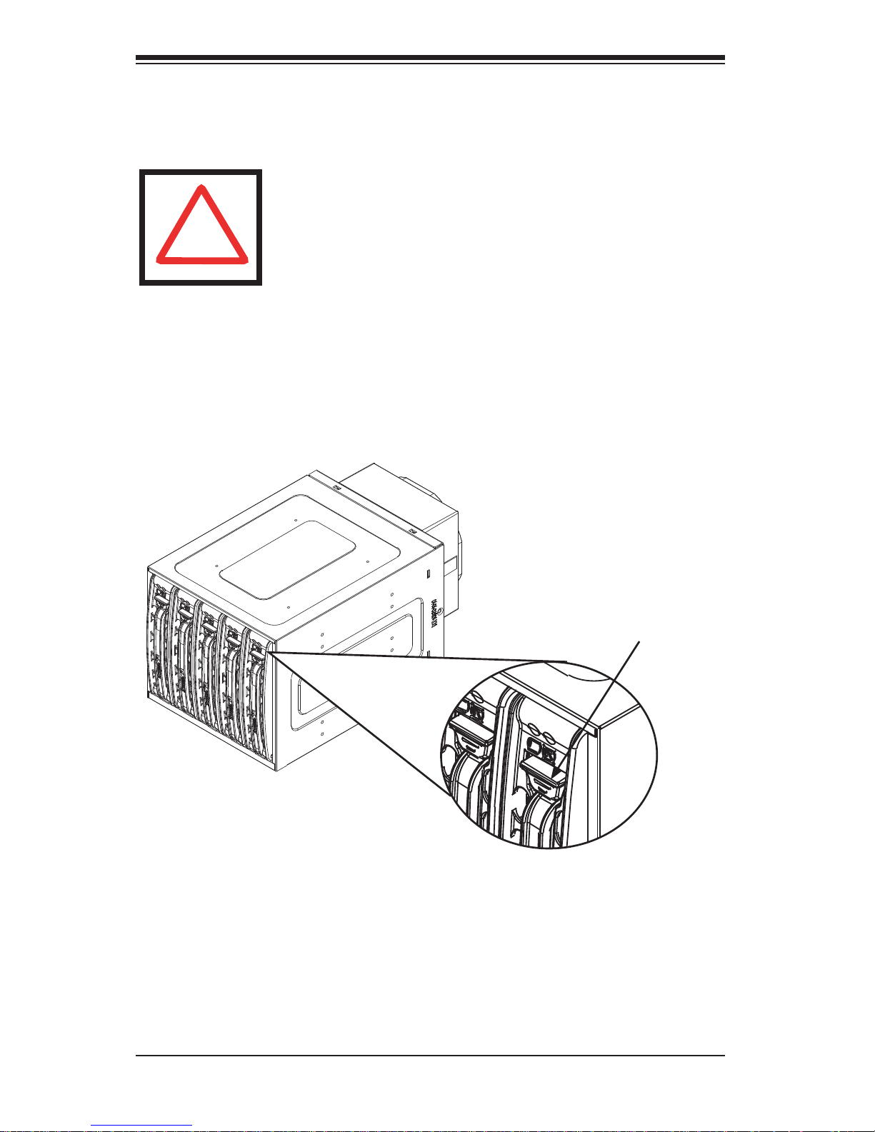
Release Button
Figure 4-1: Hard Drive Release Button
Removing Hard Drives from the Mobile Rack
Push the release button on the hard drive, which will extend the drive handle1.
Use the drive handle to carefully pull the drive from the mobile rack.2.
4-2
Page 22
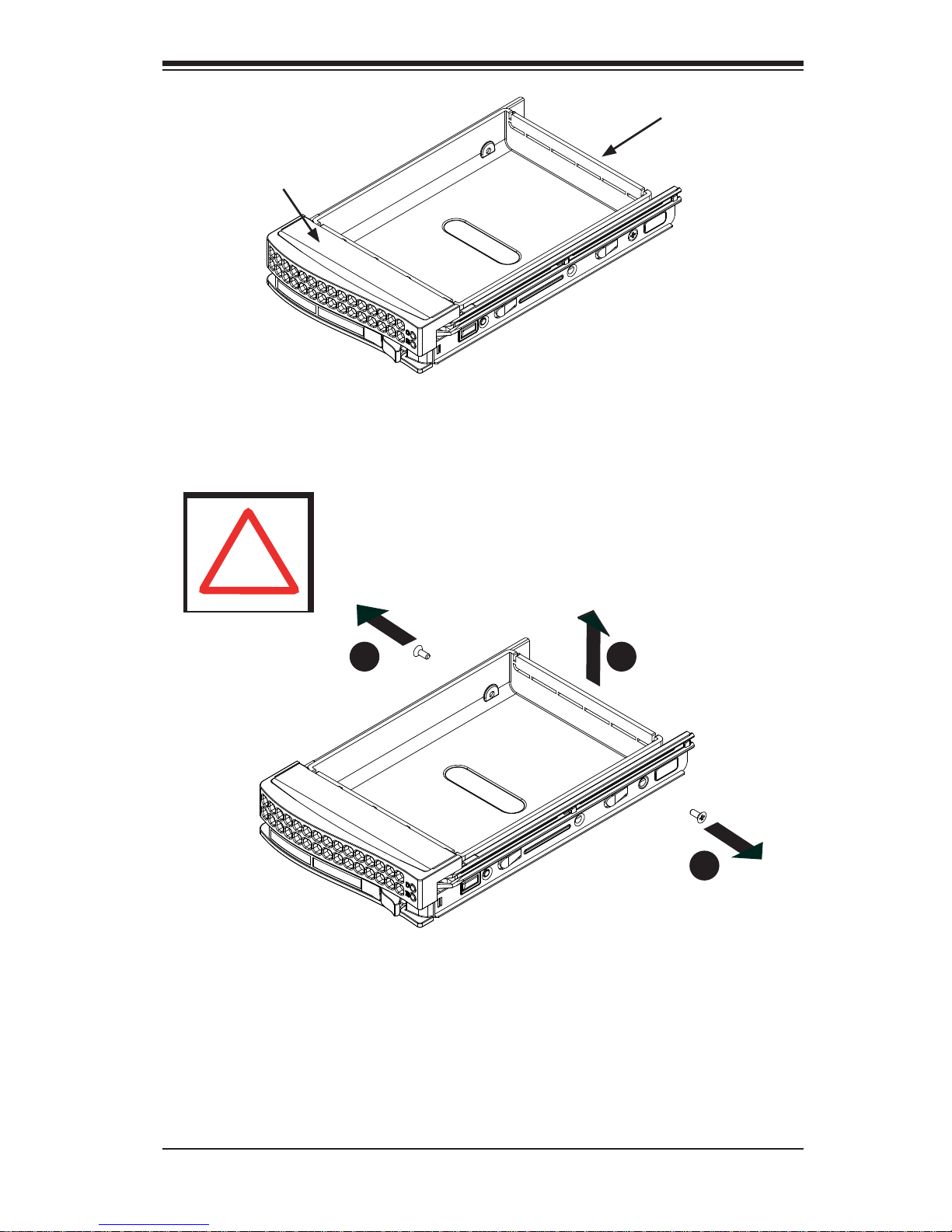
Drive Carrier
Safety Information and Technical Specifi cations
Dummy Drive
Figure 4-2: Chassis Drive Carrier
!
Warning: Except for short periods of time while swapping
hard drives, do not operate the server with the mobile rack
hard drive bays empty. The hard drive carrier must have a
hard drive or dummy drive installed.
1
1
2
1
1
1
Figure 4-3: Removing Dummy Drive from Carrier
Installing a Hard Drive into the Hard Drive Carrier
Remove the two screws holding securing the dummy drive to the carrier.1.
Remove the dummy drive from the carrier.2.
4-3
Page 23
M35TQ Mobile Rack User's Guide
SAS/SATA or SCSI
Hard Drive
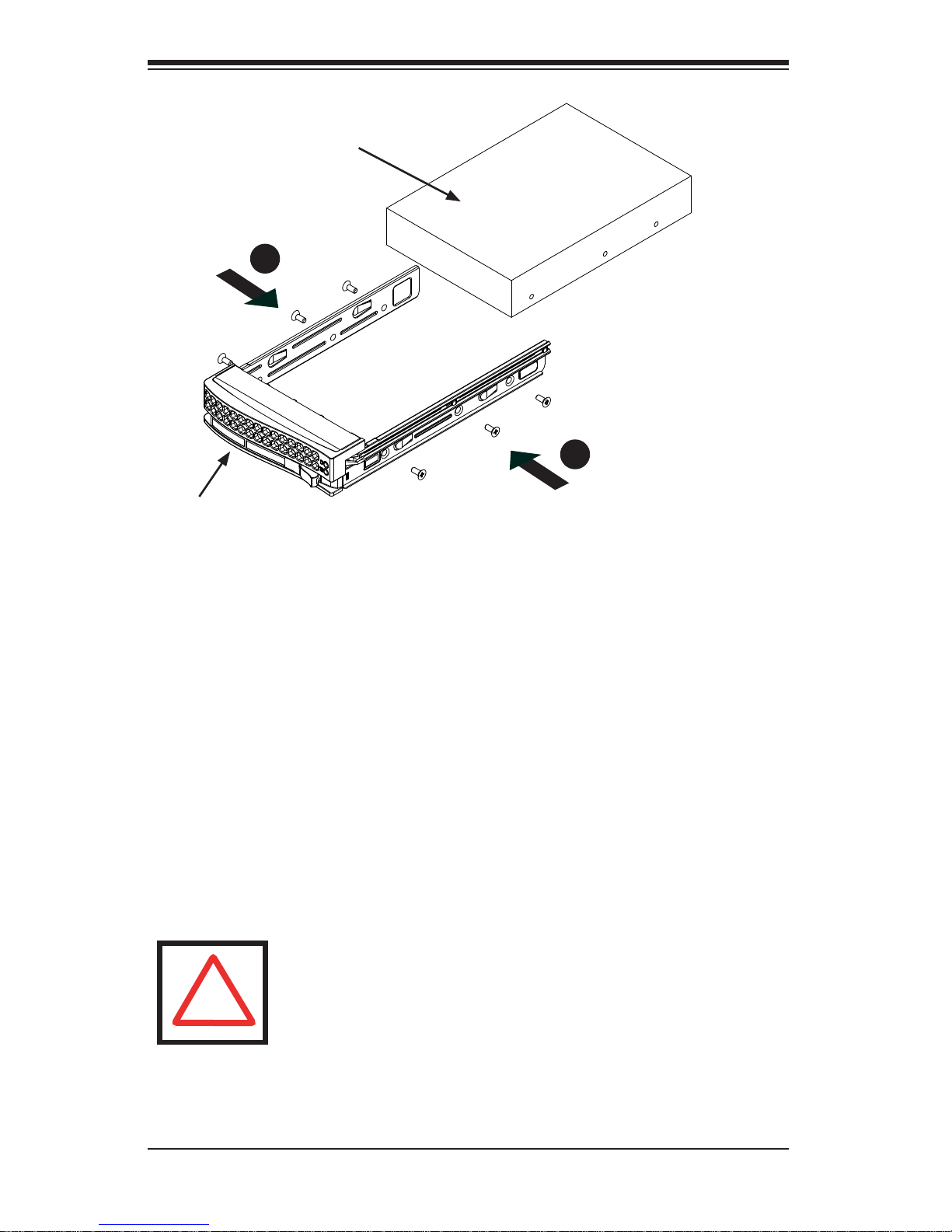
4
1
4
1
Drive Tray
Install a new drive into the carrier with the printed circuit board side facing 3.
downward so that the mounting holes in the drive align with those in the carrier.
Secure the hard drive to the carrier with the six screws provided.4.
Return the drive carrier to the mobile rack. Make sure that the drive carrier 5.
handle is returned to the closed and locked position. Repeat these steps for
each hard drive you want to install.
!
Figure 4-4: Installing a Hard Drive
Warning! Enterprise level hard disk drives are recommended
for use in Supermicro chassis and servers. For information on
recommended HDDs, visit the Supermicro Web site at http://
www.supermicro.com/products/nfo/storage.cfm
4-4
Page 24
Safety Information and Technical Specifi cations
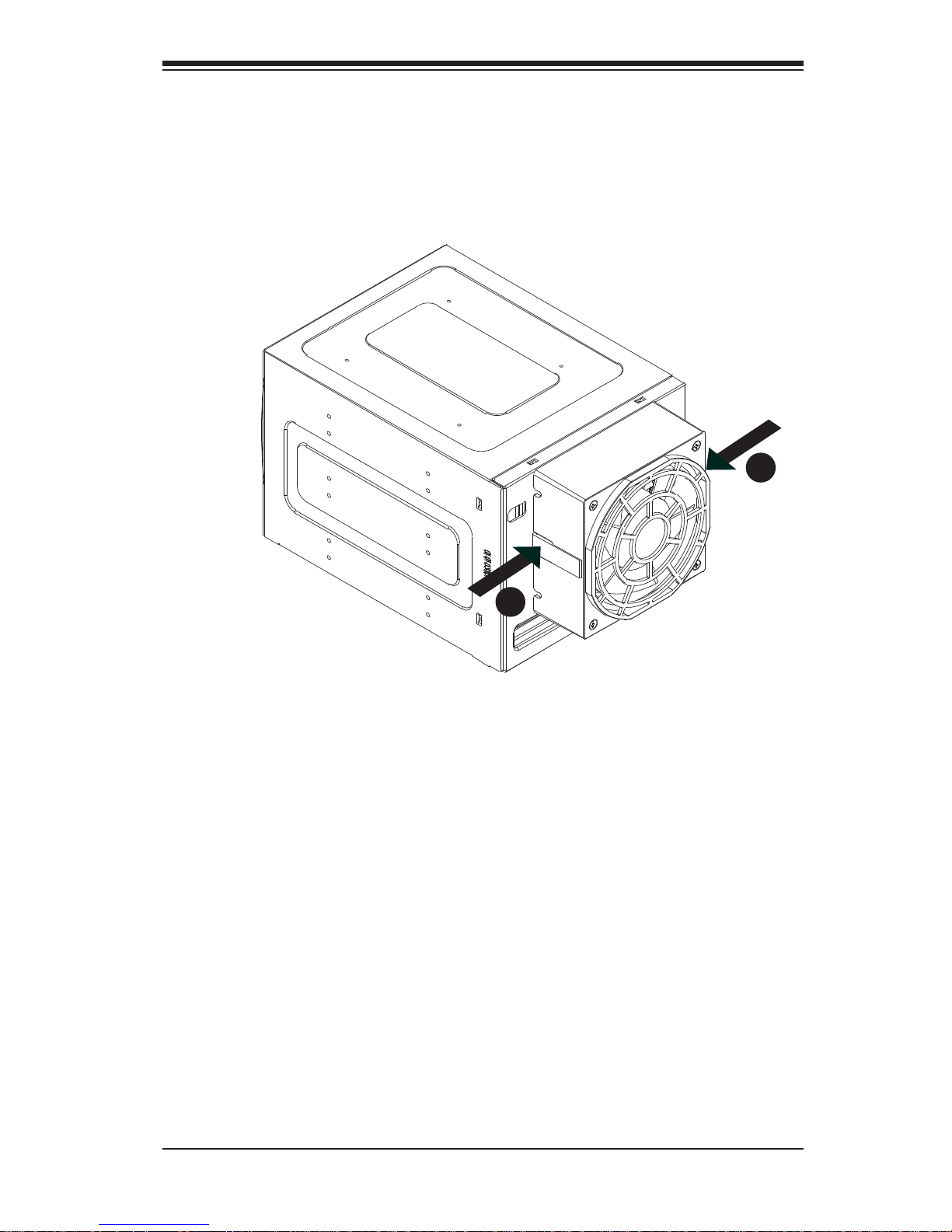
Connecting Cables to the Mobile Rack
Before connecting cables the mobile rack, the exhaust fan must be removed. In
some circumstances, the backplane may need to be removed.
1
1
1
1
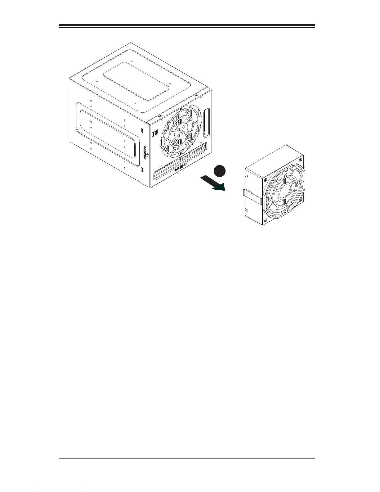
Figure 4-5: Removing Mobile Rack Fan
Removing the Exhaust Fan and Connecting SAS/SATA Cables
Simultaneously press inward on the tabs on each side of the fan housing.1.
4-5
Page 25
M35TQ Mobile Rack User's Guide
2
1
Figure 4-6: Removing Mobile Rack Fan
Pull the exhaust fan off the rear of the mobile rack.2.
4-6
Page 26

Safety Information and Technical Specifi cations
3
1
Figure 4-7: Removing Mobile Rack Fan
Remove the bracket screw from the side of the mobile rack.3.
Pull the bracket from the rear of the mobile rack.4.
Connect the SAS/SATA cables and power cables to the backplane of the 5.
mobile rack.
Replace the bracket, bracket screw, and fan on the mobile rack and recon-6.
nect power to the chassis.
4
1
4-7
Page 27

M35TQ Mobile Rack User's Guide
Backplane Screw
Locations
Figure 4-8: Removing Mobile Rack Backplane (Optional)
Additional Optional Installation Information
If necessary, before reassembling the mobile rack, the backplane may be removed.
To remove the mobile rack backplane, remove the six screws securing the backplane, and carefully pull the backplane from the rear of the mobile rack.
4-8
Page 28

Safety Information and Technical Specifi cations
Notes
4-9
Page 29

M35TQ Mobile Rack User's Guide
The products sold by Supermicro are not intended for and will not be used in life support systems, medical equipment, nuclear facilities or systems, aircraft, aircraft devices,
aircraft/emergency communication devices or other critical systems whose failure to perform be reasonably expected to result in signifi cant injury or loss of life or catastrophic
property damage. Accordingly, Supermicro disclaims any and all liability, and should
buyer use or sell such products for use in such ultra-hazardous applications, it does so
entirely at its own risk. Furthermore, buyer agrees to fully indemnify, defend and hold
Supermicro harmless for and against any and all claims, demands, actions, litigation,
and proceedings of any kind arising out of or related to such ultra-hazardous use or
sale.
Disclaimer (cont.)
4-10
 Loading...