

Page 1

Embedded BMC/IPMI
User's Guide
Revision 2.0
Page 2

Manual Revision 2.0
Release Date: July 18, 2012
Unless you request and receive written permission from Super Micro Computer, Inc., you may not
copy any part of this document.
Information in this document is subject to change without notice. Other products and companies
referred to herein are trademarks or registered trademarks of their respective companies or mark
holders.
Copyright © 2012 by Super Micro Computer, Inc.
All rights reserved.
Printed in the United States of America
The information in this User’s Manual has been carefully reviewed and is believed to be accurate.
The vendor assumes no responsibility for any inaccuracies that may be contained in this document,
makes no commitment to update or to keep current the information in this manual, or to notify any
person or organization of the updates. Please Note: For the most up-to-date version of this
manual, please see our web site at www.supermicro.com.
Super Micro Computer, Inc. ("Supermicro") reserves the right to make changes to the product
described in this manual at any time and without notice. This product, including software and documentation, is the property of Supermicro and/or its licensors, and is supplied only under a license.
Any use or reproduction of this product is not allowed, except as expressly permitted by the terms
of said license.
IN NO EVENT WILL SUPER MICRO COMPUTER, INC. BE LIABLE FOR DIRECT, INDIRECT,
SPECIAL, INCIDENTAL, SPECULATIVE OR CONSEQUENTIAL DAMAGES ARISING FROM THE
USE OR INABILITY TO USE THIS PRODUCT OR DOCUMENTATION, EVEN IF ADVISED OF
THE POSSIBILITY OF SUCH DAMAGES. IN PARTICULAR, SUPER MICRO COMPUTER, INC.
SHALL NOT HAVE LIABILITY FOR ANY HARDWARE, SOFTWARE, OR DATA STORED OR USED
WITH THE PRODUCT, INCLUDING THE COSTS OF REPAIRING, REPLACING, INTEGRATING,
INSTALLING OR RECOVERING SUCH HARDWARE, SOFTWARE, OR DATA.
Any disputes arising between manufacturer and customer shall be governed by the laws of Santa
Clara County in the State of California, USA. The State of California, County of Santa Clara shall be
the exclusive venue for the resolution of any such disputes. Supermicro's total liability for all claims
will not exceed the price paid for the hardware product.
FCC Statement: Refer to Supermicro's web site for FCC Compliance Information.
California Best Management Practices Regulations for Perchlorate Materials: This Perchlorate
warning applies only to products containing CR (Manganese Dioxide) Lithium coin cells. “Perchlorate
Material-special handling may apply. See www.dtsc.ca.gov/hazardouswaste/perchlorate”.
WARNING: Handling of lead solder materials used in this
product may expose you to lead, a chemical known to
the State of California to cause birth defects and other
reproductive harm.
Appendix A and Appendix B included in this user's guide are used with permission
from AMI. AMI is the legal owner of these documents. Supermicro has not veried the
accuracy of the contents and assumes no responsibility with regard to any errors or
omissions in these documents.
Page 3

Preface
About this User's Guide
This user guide is written for system integrators, PC technicians and
knowledgeable PC users who intend to congure the IPMI settings supported by
the Nuvoton WPCM450 BMC Controller embedded in Supermicro's motherboards.
It provides detailed information on how to congure the IPMI settings supported by
the Nuvoton WPCM450 chip.
Note: Nuvoton Technology is a subsidiary of Winbond Corp.
User's Guide Organization
Chapter 1 provides an overview to the Nuvoton WPCM450 Controller. It also intro-
duces the features and the functionality of IPMI.
Chapter 2 provides detailed instructions on how to congure the IPMI settings
supported by the embedded WPCM450 Controller.
Chapter 3 provides the answers to frequently asked questions.
Conventions Used in the User's Guide
Special attention should be given to the following symbols for proper IPMI con-
guration.
Warning: Important information given to avoid IPMI conguration errors.
Note: Additional Information given to ensure correct IPMI conguration
and proper system setup.
iii
Preface
Page 4

Embedded BMC/IPMI User's Guide
Contacting Supermicro
Headquarters
Address: Super Micro Computer, Inc.
980 Rock Ave.
San Jose, CA 95131 U.S.A.
Tel: +1 (408) 503-8000
Fax: +1 (408) 503-8008
Email: marketing@supermicro.com (General Information)
support@supermicro.com (Technical Support)
Web Site: www.supermicro.com
Europe
Address: Super Micro Computer B.V.
Het Sterrenbeeld 28, 5215 ML
's-Hertogenbosch, The Netherlands
Tel: +31 (0) 73-6400390
Fax: +31 (0) 73-6416525
Email: sales@supermicro.nl (General Information)
support@supermicro.nl (Technical Support)
rma@supermicro.nl (Customer Support)
Asia-Pacic
Address: Super Micro Computer, Inc.
4F, No. 232-1, Liancheng Rd.
Chung-Ho Dist., New Taipei City 235
Taiwan, R.O.C.
Tel: +886-(2) 8226-3990
Fax: +886-(2) 8226-3991
Web Site: www.supermicro.com.tw
Technical Support:
Email: support@supermicro.com.tw
Tel: 886-2-8228-1366, ext.132 or 139
iv
Page 5

Preface
Notes
v
Page 6

vi
Embedded BMC/IPMI User's Guide
Table of Contents
Preface
Chapter 1 Introduction
1-1 An Overview of the WPCM 450 BMC Controller ............................................ 1-1
WPCM450 DDR2 Memory Interface ............................................................... 1-1
WPCM450 PCI System Interface .................................................................... 1-1
Other Features Supported by the WPCM BMC Controller ............................. 1-1
1-2 WPCM450 Block Diagram .............................................................................. 1-3
1-3 A Brief Introduction to the IPMI ....................................................................... 1-3
1-4 Motherboards Supported ................................................................................ 1-4
1-5 An Important Note to the User ........................................................................ 1-4
Chapter 2 Conguring the IPMI Settings
2-1 Conguring BIOS ............................................................................................ 2-1
To Set the IP/MAC Addresses Using the IPMICFG Utility ............................ 2-3
Accessing the Baseboard Management Controller ........................................ 2-5
Using the Internet Browser ............................................................................. 2-5
2-2 Using IE* to Access the BMC/IPMI Settings from Your Computer ................. 2-6
2.2.1 To Log In ................................................................................................ 2-6
2.2.2 IPMI Main Page ..................................................................................... 2-7
2.3 Server Health ............................................................................................ 2-9
2.4 Conguration ........................................................................................... 2-13
2.5 Remote Control - the Main Menu ........................................................... 2-28
2.6 Maintenance ............................................................................................ 2-40
2.7 Miscellaneous ......................................................................................... 2-42
2.8 Language ................................................................................................ 2-44
Chapter 3 Frequently Asked Questions
3-1 Frequently Asked Questions ........................................................................... 3-1
Appendix A Flash Tools
A-1 Overview .........................................................................................................A-1
A-2 Flashing the BMC Firmware in the DOS Environment ................................... A-1
A-3 Flashing the BMC Firmware in the Windows Environment ............................A-2
A-4 Flashing the BMC Firmware in the Linux Environment ..................................A-5
A-5 Firmware Recovery .........................................................................................A-7
Page 7

1-1
Chapter 1: Introduction
Chapter 1
Introduction
1-1 An Overview of the WPCM 450 BMC Controller
The Nuvoton WPCM450 Controller, a Baseboard Management Controller (BMC),
supports 2D/VGA-compatible Graphic Cores with PCI interface, creating multi-media
virtualization via Keyboard/Video/Mouse Redirection (KVMR). The WPCM450 Con-
troller is ideal for networking management.
The WPCM450 Controller interfaces with the host system via PCI connections to
communicate with Graphic cores. It supports USB 2.0 and 1.1 for remote keyboard/
mouse/virtual media emulation. It also provides LPC interface support to control
Super IO functions. The WPCM450 Controller is connected to the network via an
external Ethernet PHY module or shared NCSI connections.
The WPCM450 communicates with onboard components via six SMBus interfaces,
PECI (Platform Environment Control Interface) buses, and General Purpose I/O
ports.
WPCM450 DDR2 Memory Interface
The WPCM450 supports 16-bit DDR2 memory with a speed of up to 220 MHz. The
motherboard supports 128 MB of shared memory between the BMC and onboard
graphics card. For best signal integrity, the WPCM450 provides point-to-point con-
nections.
WPCM450 PCI System Interface
The WPCM450 provides the 32-bit, 33 MHz 3.3V PCI interface, which is compliant
with the PCI Local Bus Specication Rev. 2.3. The PCI system interface connects
to the onboard PCI Bridge used by the graphics controller.
Other Features Supported by the WPCM BMC Controller
The WPCM450 supports the following features.
•IPMI 2.0
•Serial over LAN
•KVM over LAN
Page 8

Embedded BMC/IPMI User's Guide
1-2
•LAN Alerting-SNMP Trap
•Event Log
•X-Bus parallel interface for I/O expansion
•Multiple ADC inputs, Analog and Digital Video outputs
•Two serial ports (optional)
•DDR2 SDRAM memory for frame-buffer, rmware support and data storage
•SPI Flash Host BIOS and rmware bootstrap program supported
•Reduced Media Independent Interface (RMII)
•OS (Operating System) Independency
•Provides remote Hardware Health Monitoring via IPMI. Key features include
the following:
• Temperature monitoring
• Fan speed monitoring
• Voltage monitoring
• Power status monitoring, chassis intrusion monitoring
• Remote power control to power-on, power-off or reboot a system
• Remote access to text-based, graphic-based system information,
including BIOS congurations and OS operation information (KVM)
• Remote management of utility/software applications
•Provides Network Management Security via remote access/console redirection.
Key features include:
• User authentication enhancement
• Encryption support enhancement, allowing for password congura-
tion security to protect sensitive data transferring via Serial over
LAN
•Supports the following Management tools: IPMIView, CLI (Command Line
Interface)
•RMCP+ protocol supported
Page 9
1-3
Chapter 1: Introduction
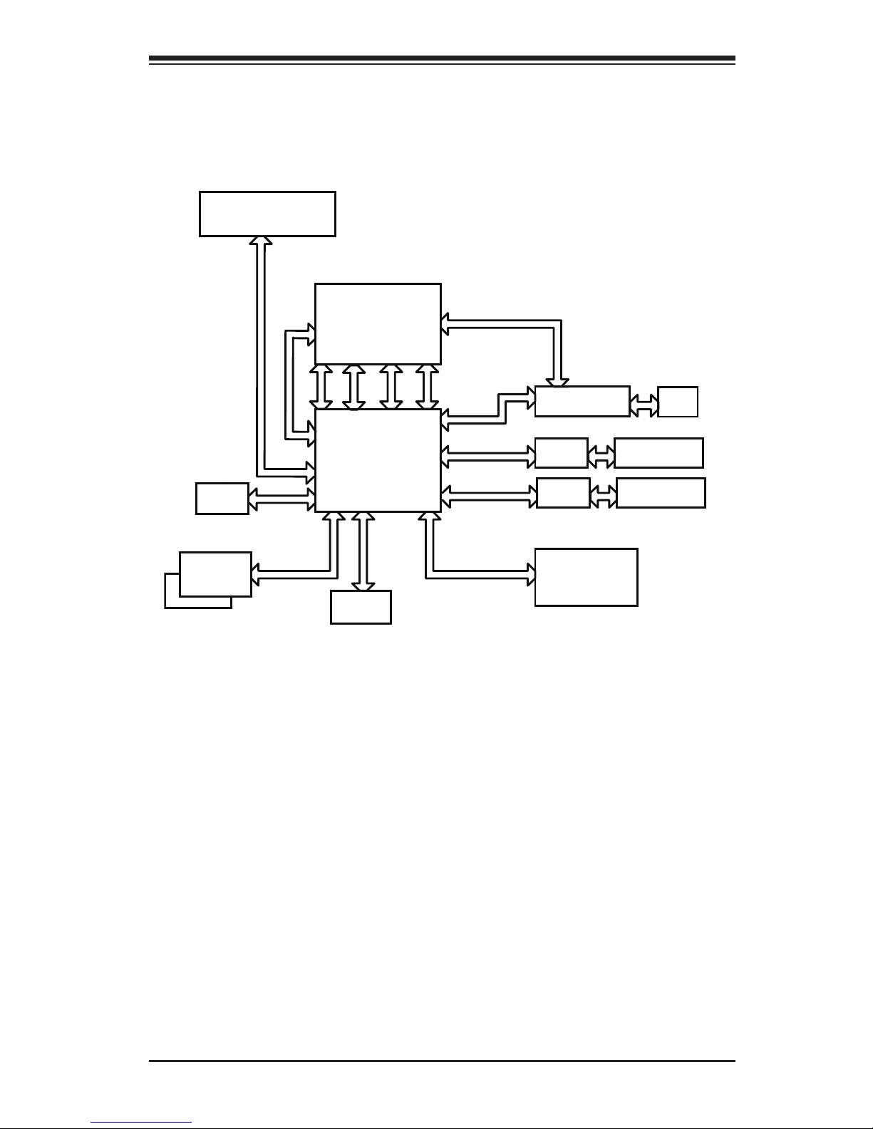
1-2 WPCM450 Block Diagram
The following diagram represents a typical system setup for the WPCM450 Con-
troller.
WPCM450
Sensors
DDR2
LPC
SPI
Serial Port
South Bridge
PCI
USB
1.1
USB
2.0
Ethernet CTRL
RMII
RJ45
PROCESSOR
RS232
Serial Port
NOR Flash
PECI
Wake-up & CTRL
VGA
PCI-E
PHY
Onboard LAN1
RJ45
Dedicated LAN
RMII
1-3 A Brief Introduction to the IPMI
The Intelligent Platform Management Interface (IPMI) Specication provides remote
access to multiple users from different locations for networking. It also allows a
system administrator to monitor system health and manage computer events from
a remote location.
IPMI operates independently of the operating system. When used in conjunction
with the IPMIView, which is an IPMI-compliant management software pre-installed
in a computer by Supermicro, the WPCM450 BMC Controller provides serial link
connections between the South Bridge and other onboard system components, al-
lowing for network interfacing via remote access. With the WPCM450 Controller and
the IPMIView software built in, a Supermicro motherboard allows an administrator
to access, monitor, diagnose and manage a computer system from a remote site.
It also provides remote access to multiple users from different locations for system
maintenance and network management.
Page 10

Embedded BMC/IPMI User's Guide
1-4
Intel UP Motherboards
supported
Intel DP Motherboards
supported
AMD Motherboards
supported
X7SB3-F X7DCT-3F H8DMT-F
X8ST3-F X7DCT-3IBXF H8DMT-IBXF
X8STi-F X7DCT-LF
X8STi-3F X8DAH+-F
X8DT3-F
X8DT3-LN4F
X8DTH-6F
X8DTH-iF
X8DTi-F
X8DTi-LN4F
X8DTT-F
X8DTT-IBQF
X8DTT-IBXF
X8DTU-F
1-4 Motherboards Supported
This version of Embedded BMC/IPMI is supported by the motherboards listed in
the table below. If your motherboard is not included in the table, please refer to the
motherboard product page on our website at www.supermicro.com and download
the right BMC/IPMI user's guide for your motherboard.
1-5 An Important Note to the User
The graphics shown in this user's guide were based on the latest information
available at the time of publishing of this guide. The IPMI screens shown on your
computer may or may not look exactly like the screen shown in this user's guide.
Page 11

Chapter 2: Conguring BMC/IPMI Settings
2-1
Chapter 2
ConguringtheIPMISettings
With the Nuvoton WPCM450 BMC Controller and the IPMIView rmware built in,
Supermicro motherboards allow the user to access, monitor, manage and interface
with multiple systems in various remote locations. The necessary rmware for ac-
cessing and conguring the IPMI settings are available on Supermicro's website at
hppt://www.supermcro.com/products/nfo/ipmi.cfm. This section provides detailed
information on how to congure the IPMI settings.
2-1 ConguringBIOS
Before conguring IPMI, follow the instructions below to congure the system BIOS
settings.
Enabling COM Port for SOL (IPMI)
1. Press the <Del> key at bootup to enter the BIOS Setup utility.
2. Select Advanced and press <Enter> to enter the Advanced menu.
3. From the Advanced menu, select Remote Access and press <Enter>.
4. Make sure that the COM port for SOL (COM2 or COM3) is enabled (marked
with "*"). If not, Select the port for SOL and press <Enabled>. (For IPMI to
work properly, BIOS will set the console redirection on this port by default.)
Page 12
2-2
Embedded BMC/IPMI User's Guide
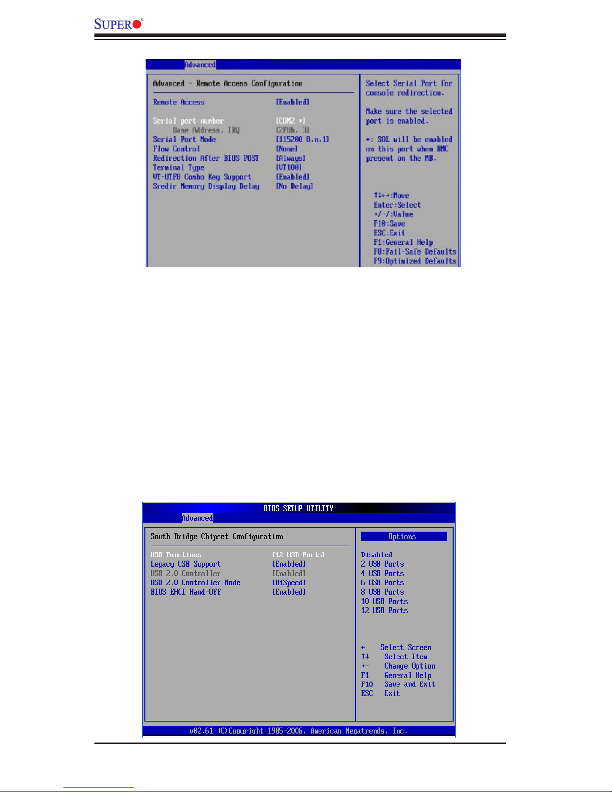
B. Enabling All Onboard USB ports
1. Press the <Del> key at bootup to enter the BIOS Setup utility.
2. Select Advanced and press <Enter> to enter the Advanced menu.
3. Select Advanced Chipset Control and press <Enter>.
4. From the Advanced Chipset Control submenu, select South Bridge Control
and press <Enter>.
5. Make sure that all onboard USB ports are enabled (highlighted). If not, Select
USB Functions and press <Enabled> or select the number of onboard USB
ports or press <Enter>to enable all onboard USB ports. (This is required for
KVM to work properly.)
Page 13
Chapter 2: Conguring BMC/IPMI Settings
2-3
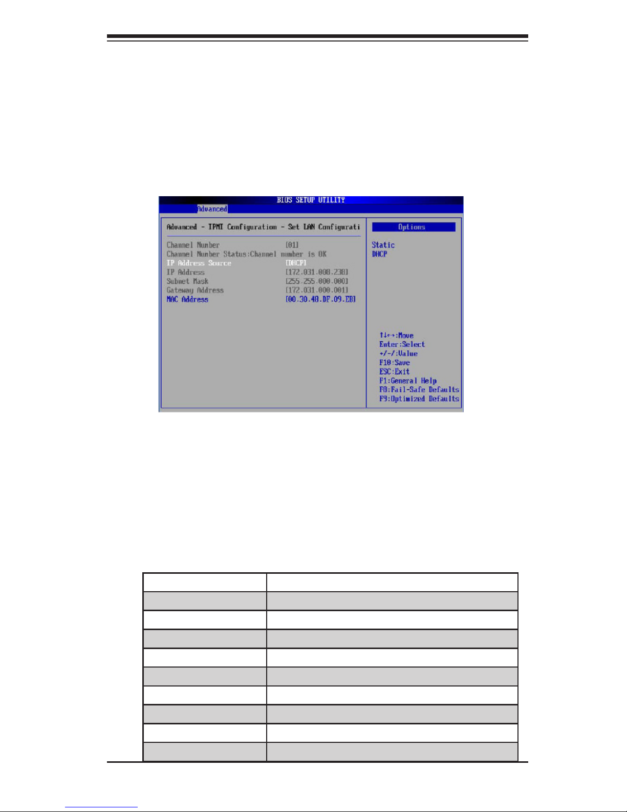
C . C o n g u r i n g I P a n d M A C A d d r e s s e s u s i n g B I O S
1. Press the <Del> key at bootup to enter the BIOS Setup utility.
2. Select Advanced and press <Enter> to enter the Advanced menu.
3. From the Advanced menu, select IPMI Conguration and press <Enter>.
4. From the IPMI Conguration submenu, select Set LAN Conguration and
press <Enter> to set IP and MAC addresses.
To Set the IP/MAC Addresses Using the IPMICFG Utility
1. Run the ipmicfg utility from the bootable CD that came with your shipment.
2. Follow the instructions given in the Readme.txt le to congure Gateway IP/
Netmask IP addresses, to enable/disable DHCP and to congure other IPMI
settings.
IPMICFG Version 1.35 (Build 2010-04-28) Copyright 2010 Super Micro Computer,
Inc. Usage: IPMICFG Parameters (Example: IPMICFG -m 172.31.1.84)
-m Shows IP and MAC
-m IP Sets IP (format: ###.###.###.###)
-a MAC Sets MAC (format: ##:##:##:##:##:##)
-k Shows Subnet Mask
-k Mask Sets Subnet Mask (format: ###.###.###.###)
-dhcp Gets the DHCP status
-dhcp on Enables the DHCP
-dhcp off Disables the DHCP
-g Shows Gateway IP
-g IP Sets Gateway IP (format: ###.###.###.###)
Page 14

2-4
Embedded BMC/IPMI User's Guide
-r BMC cold reset
-garp on Enables the Gratuitous ARP
-garp off Disables the Gratuitous ARP
-fd Resets to the factory defaults
-ver Gets the rmware revision
-vlan Gets VLAN status
-vlan on (VLANtag) Enables the VLAN and sets the VLAN tag (If VLAN
tag is not given, it uses previously saved value.)
-vlan off Disables the VLAN
-raw Sends a RAW IPMI request and print the response.
Format: NetFn LUN Cmd [Data1...DataN].
-sdr Shows SDR records and reading
-sdr del <SDR ID> Deletes SDR record
-sdr backup <FILE> Backups SDR to le
-sdr restore <FILE> Restores SDR from le
-sdr ver [<V1><v2>] Retrieves and sets SDR version (V1, V2)
-sel info Shows SEL info
-sel list Shows SEL records
-sel del Deletes all SEL records
-fru info Shows FRU inventory area info
-fru list Shows all FRU values
-fru help Shows FRU Write help
-fru cthelp Shows chassis type code
-fru <Field> Shows FRU eld value
-fru <Field> <Value> Writes FRU
-fru backup <File> Backs up FRU to le
-fru restore <File> Restores FRU from le
-fru ver [<V1> <V2>] Retrieves and sets FRU version (V1, V2)
Page 15

Chapter 2: Conguring BMC/IPMI Settings
2-5
Accessing the Baseboard Management Controller
1. Connect a LAN cable to the onboard LAN1 port or the dedicated IPMI LAN
port.
2. Choose a computer connected to the same network and open the IPMIView
utility.
3. Go to File>New>System. Enter System Name, IP Address of LAN1 or the
dedicated LAN, Description in the appropriate elds and press <Enter>.
4. Select the system from the IPMI Domain. Enter the Login ID and Password in
the appropriate elds to login to the IPMIView utility.
Using the Internet Browser
1. Connect a LAN cable to the onboard LAN1 port or the dedicated IPMI LAN
port.
2. Choose a computer that is connected to the same network and open the
browser.
3. Enter the IP address of each server that you want to connect to in the ad-
dress bar in your browser.
4. Once your machine is connected to the remote server, the Log-In screen as
shown on the next page will display.
Note 1: If you wish to use the IPMI-dedicated LAN port for your network
connections, be sure to connect an RJ45 cable to your dedicated LAN port
before you activate the BMC (at rst power-on or cold reset). Otherwise,
the BMC will look for a shared LAN port to connect to if the IPMI-dedicated
LAN cable is not detected upon BMC activation.
Note 2: However, if you should decide to use the IPMI-dedicated LAN port
for a network connection, please perform a BMC cold reset or power cycle
reset for the dedicated LAN to be detected.
Page 16
2-6
Embedded BMC/IPMI User's Guide
2-2 Using IE* to Access the BMC/IPMI Settings from
Your Computer
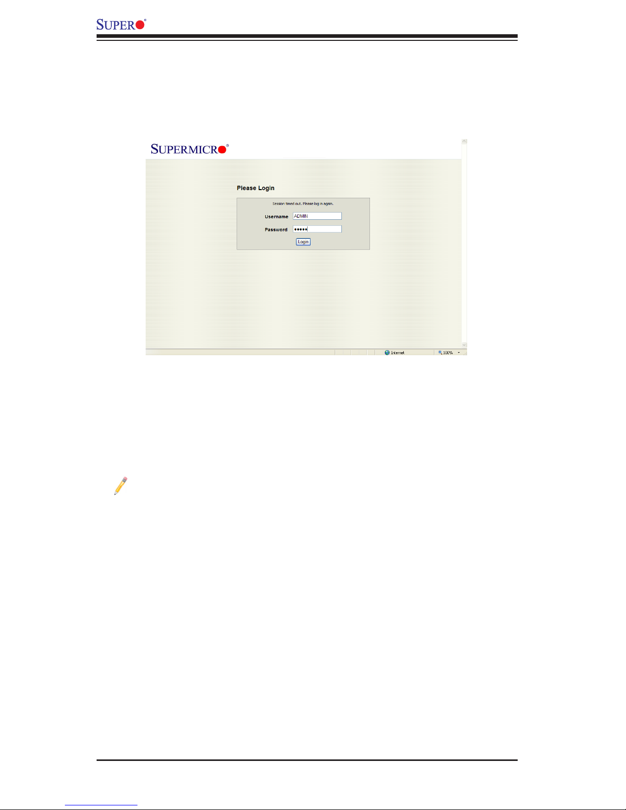
2.2.1 To Log In
Once you are connected to the remote server, the following screen will display.
1. Enter your Username.
2. Enter your Password and click <Login>.
3. The Home Page will display on the next page.
Note 1: To use the IPMIView Utility to access BMC/IPMI settings, refer to the
IPMIView User's Guide for instructions.
Note 2: The manufacturer default username and password are ADMIN. Once
you have logged into the BMC using the manufacturer default password, be sure
to change your password for system security.
Note 3: For IPMI to work properly, please enable all onboard USB ports and the
COM port designated for SOL (IPMI) on the motherboard. All USB ports and the
COM port for IPMI are enabled in the system BIOS by default. The COM port
for IPMI is marked with "*" in the BIOS. It is usually listed as COM2 or COM3 in
the BIOS. Refer to Section 2-1 Conguring BIOS.
Page 17
Chapter 2: Conguring BMC/IPMI Settings
2-7
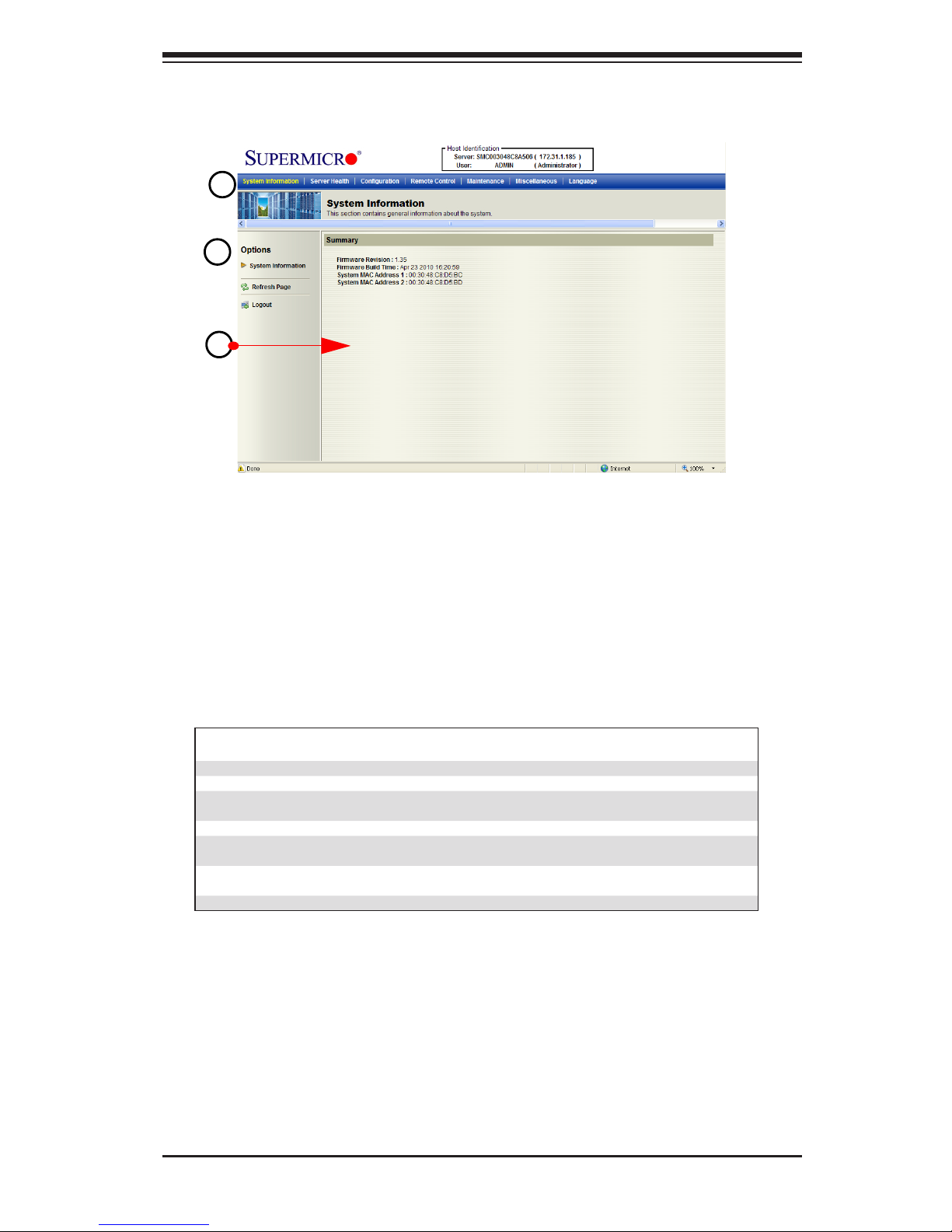
2.2.2 IPMI Main Page
Once you are logged into the IPMI utility, the IPMI Main page will display.
The IPMI screen contains the following three sections:
• The Submenu Bar (Top)
•The Options Window (Left)
•The Main Display area (Center)
1. Submenu Bar
The submenu bar on the top lists the following submenus:
Submenu Bar
System Information This submenu displays system information.
Server Health This submenu displays server health monitoring status.
Conguration This submenu allows the user to congure the IPMI settings.
Remote Control This submenu allows the user to launch KVM Console and perform
power control & management.
Maintenance This submenu allows the user to update the rmware and reset the unit.
Miscellaneous This submenu allows the user to post snooping codes and to launch the
SOL console.
Language This submenu allows the user to select a language setting. (Currently,
only English is available.)
? Help Click this item to nd an answer when you have a question.
1
2
3
Page 18

2-8
Embedded BMC/IPMI User's Guide
2. The Options window
The Options window on the left side allows the user to quickly navigate through
different submenu options.
Options window
Submenu Name
(System Information)
Click this item to display and congure a submenu items.
Refresh Page Click this icon to refresh the page.
Logout Click this icon to logout from the IPMI utility.
3. The Main Display Area
This area displays the items included in a submenu.
The following items are included in the System Information submenu.
•Firmware Revision: This item displays the current rmware revision number.
•Firmware Build Time: This item displays the time and the date when this version
of rmware was built.
•System MAC Address 1: This item displays the MAC address of the rst system
that is connected to IPMI.
•System MAC Address 2: This item displays the MAC address of the second
system that is connected to IPMI.
Page 19
Chapter 2: Conguring BMC/IPMI Settings
2-9
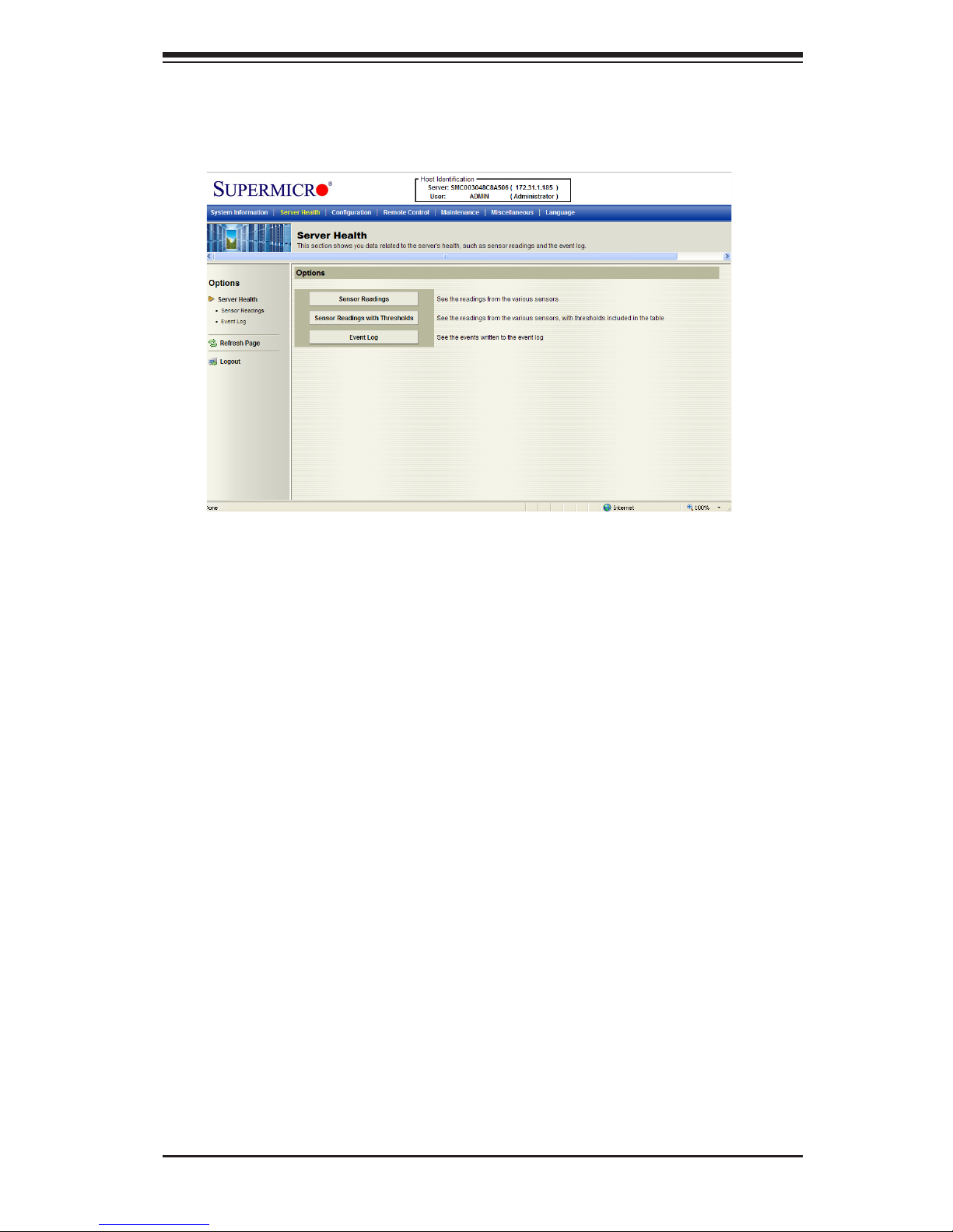
2.3 Server Health
This feature allows the user to set Server Health Settings. Click <Server Health>
to display the following submenu.
The Server Health submenu contains the following items.
•Sensor Readings
•Sensor Readings with Thresholds
•Event Log
Page 20
2-10
Embedded BMC/IPMI User's Guide
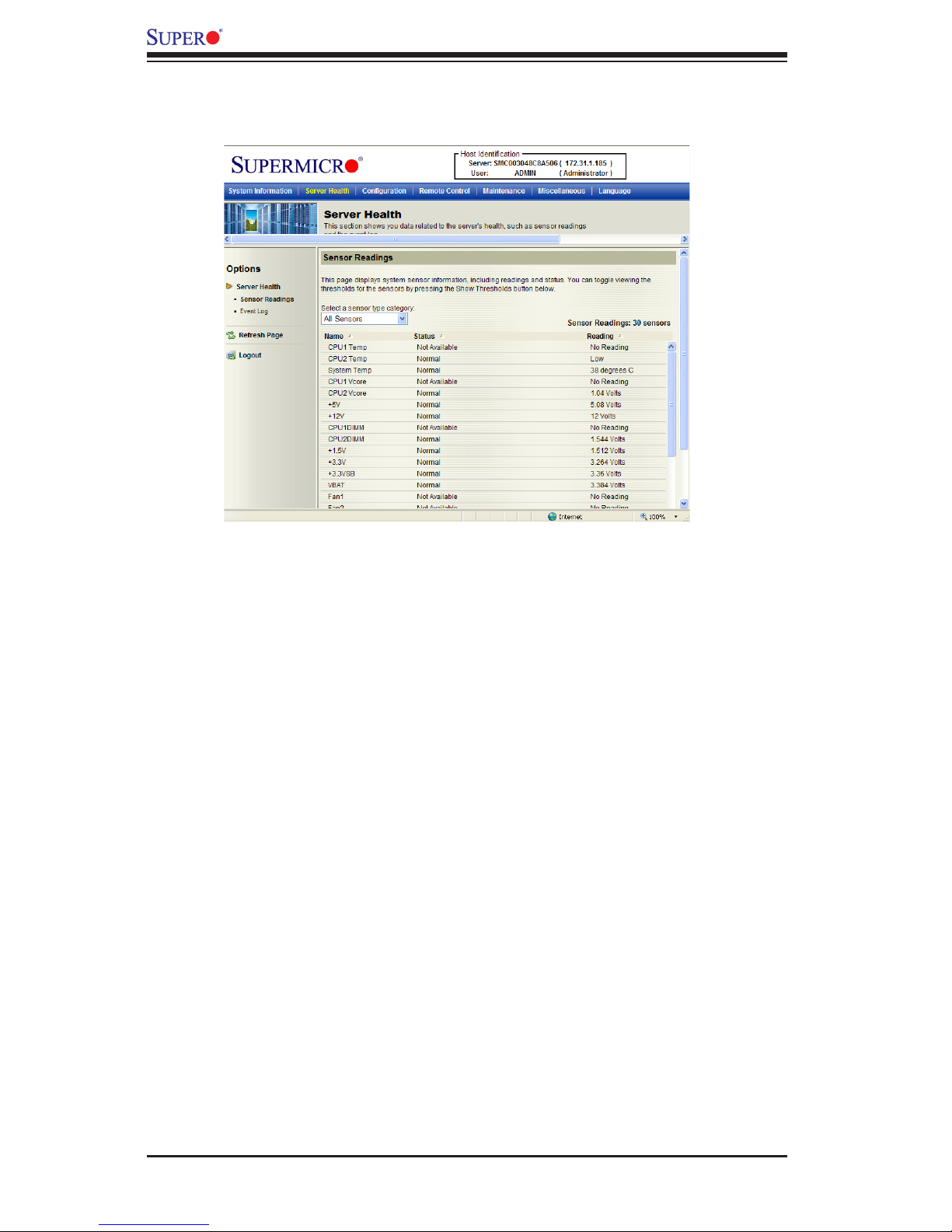
2.3.1. Sensor Readings
Click this item to display the Sensor Reading page as shown below.
•All Sensors: This item displays the readings for all sensors
•Temperature Sensors: This item displays the system temperature.
•Voltage Sensors: This item displays the following items: CPU Vcore, CPU DIMM
voltages, +3.3V, +3.3VSB, +1.5V, +12V, +5V and VBAT (Battery Voltage).
•Fan Sensors: This item displays the readings of the onboard fans.
•Power Supply: This item displays the status of power supply failure monitor-
ing.
•OEM Reserved: This item reserved for OEM use.
Page 21
Chapter 2: Conguring BMC/IPMI Settings
2-11
1
2
3
4
5
6
7
8
10
11
12
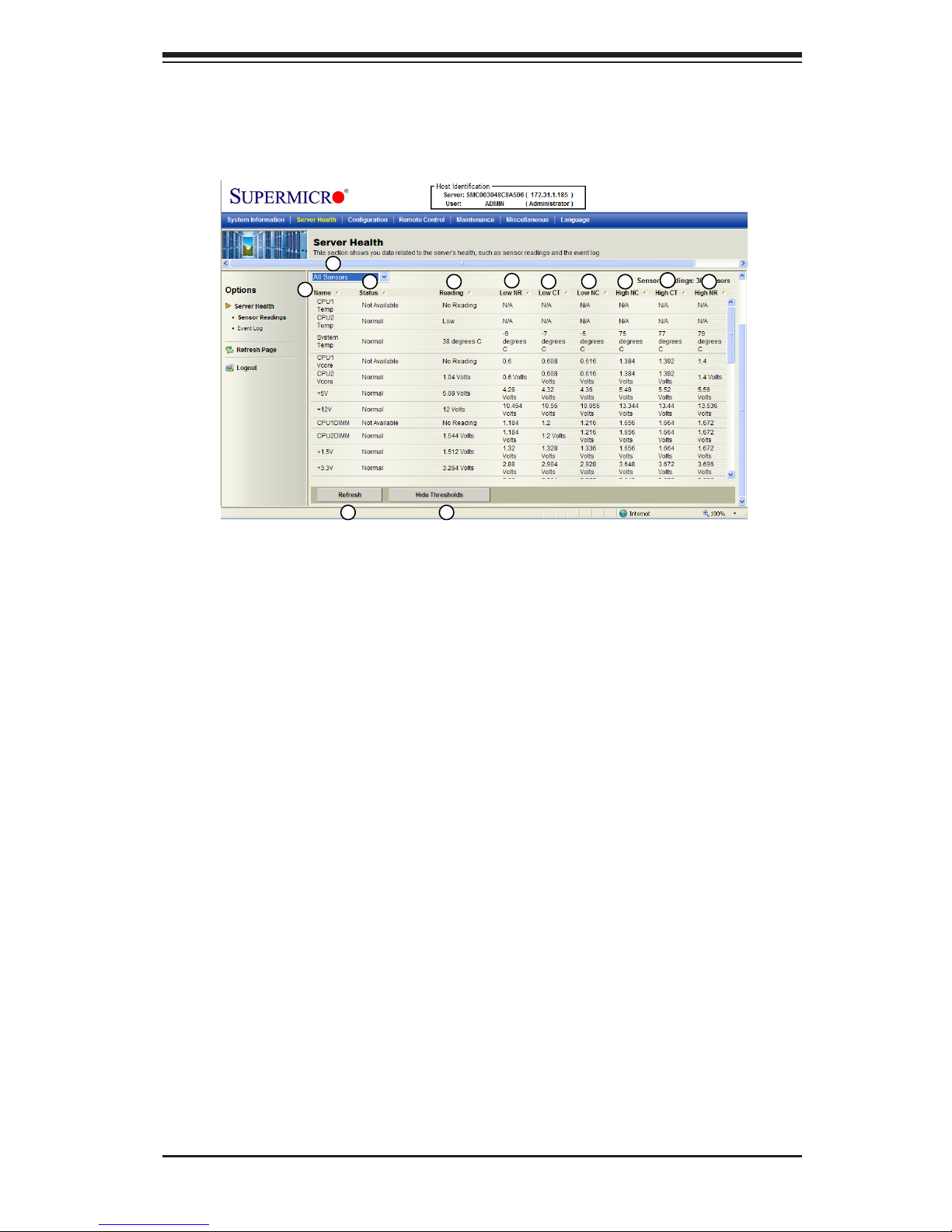
2.3.2. Sensor Readings with Thresholds
Click this item to display all sensor readings and their thresholds as shown be-
low.
1. From the pull-down menu select a sensor you want to display its readings
and thresholds.
2. Name: This item displays the name of the item being monitored.
3. Status: This item displays the status of the sensor item.
4. Reading: This item displays the reading of the sensor.
5. Low NR (Low Non-Recoverable): This is the low threshold of a non-recover-
able item. Any item with a reading below this point will not be recovered.
6. Low CT (Low Critical-Threshold): This is the low threshold of a critical item.
Any item with a reading below this threshold is in a critical state.
7. Low NC (Low Non-Critical): This is the low threshold of a non-critical item.
Any item with a reading above this threshold is not in a critical state.
8. High NC (High Non-Critical): This is the high threshold of a non-critical item.
Any item with a reading below this threshold is not in a critical state.
9
Page 22

2-12
Embedded BMC/IPMI User's Guide
9. High CT (High Critical-Threshold): This is the high threshold of a critical item.
Any item with a reading above this threshold is in a critical state.
10. High NR (High Non-Recoverable): This is the high threshold of a non-recover-
able item. Any item with a reading above this point will not be recovered.
11. Refresh: Click this tab to refresh this page.
12. Hide/(Show) Thresholds: Click this tab to hide/(or to show) the thresholds of
the items.
Page 23

Chapter 2: Conguring BMC/IPMI Settings
2-13
2.3.3. Event Log
This feature allows the user to congure Event Log settings. When you select Event
Log in Options Window the following page will display.
1
2
3
4
5
6
7
1. From the pull-down menu select an event category to show the vent log,
which includes the following categories: All Events, Sensor-Specic Events,
BIOS-Generated Events, and System-Management Software Events. In addi-
tion to these events, it is normal to see boot-up and shutdown events gener-
ated by the installed system software (OS). The table below lists examples of
these types of events.
Sensor Type Event
OS Boot A: boot completed
C: boot completed
PXE boot completed
Diagnostic boot completed
CD-ROM boot completed
ROM boot completed
Boot completed - boot device not specified
OS Stop/Shut-
down
Stop during OS load/initialization, Unexpected error dur-
ing system startup, Stopped waiting for input or power
cycle/reset
Run-time stop (a.k.a 'core dump', 'blue screen')
OS graceful stop (system powered up, but normal OS
operation has shut down and system is awaiting reset
pushbutton, power cycle or other external input)
Page 24

2-14
Embedded BMC/IPMI User's Guide
2. Event ID: This item displays the event ID of this event.
3. Time Stamp: This item displays the time when the event takes place.
4. Sensor Name: This item indicates the name of the sensor (device) to which
the event has occurred.
5. Sensor Type: This item indicates the type of the event.
6. Description: This item provides a brief description of the event.
7. Event Log: This item indicates the number of events included on the event
log.
8. Clear Event Log: Click the button to clear the event log.
Page 25

Chapter 2: Conguring BMC/IPMI Settings
2-15
2.4Conguration
This feature allows the user to congure various network settings. Click the Con-
guration on the submenu bar to display the Conguration submenu as shown
below.
Select an item to congure its settings. The items included are listed below.
•Alerts: This item allows the user to congure Alerts settings.
•Date & Time: This item allows the user to congure Date & Time settings.
•LDAP: This item allows the user to congure LDAP (Lightweight Directory Ac-
cess Protocol) settings.
•Active Directory: This item allows the user to congure settings to authenticate
and access to the Active Directory server.
•Mouse mode
•Network
•Remote Session
•SMTP: This item allows the user to congure Simple Mail Transfer Protocol
(SMTP) settings. To set up an email alert, please enter the IP address of your
mail server in the SMTP
•SSL Certicate: This item allows the user to congure Secure Sockets Layer
(SSL) certication settings.
•Users
•LAN Select
2
3
1
Page 26

2-16
Embedded BMC/IPMI User's Guide
2.4.1 Conguration - Alerts
This feature allows the user to congure Alert settings. When you click <Alerts> in
the Options window, the following screen will display.
1. Alerts: Click this item to add, to modify, to delete or to dene the setting of
an alert.
2. Alert#: This item lists Alert item numbers.
3. Alert Level: This item indicates the alert level for each alert.
4. Destination Address: This item indicates the target address of an alert.
5. Modify: Click this icon to congure or modify a selected alert.
6. Send Test Alert: Click this item to send a congured alert to its destination
(the target address) for testing.
7. Delete: Click this item to delete an alert.
Modifying Alerts
When you select an item and click <Modify>, the Modify Alert submenu will display
as shown below.
5
6
7
1
2
3
4
Page 27

Chapter 2: Conguring BMC/IPMI Settings
2-17
To modify an alert, enter the information needed for the following items:
•Alert Type: This item allows you to specify the alert type. You can select SNMP
Type or Email from the pop-up menu. For further guidance on typical inquiries
relating to SNMP, see the table below.
Item Answer
SNMP version number SNMP version 2.
MIB community name A community name is not required since
SNMP version 2 only uses traps.
MIB le location Go to http://www.supermicro.com/products/
nfo/IPMI.cfm and click “IPMI MIB (AMI)”
(right-hand side of the page).
The IPMI item you need to con-
figure so the SNMP manager
can receive the SNMP trap
The alert LAN destination address (see #4
under 2.4.1) must be set to the same IP in
as the SNMP manager.
Can I query for detailed infor-
mation on the MIB "Event" trap
items?
Detailed queries are not possible because
event mapping is based only on sensor
type, event type, and sensor offset.
A list of trap items generated for
my platform
No standard list of event traps exist be-
cause the PEF (Platform Event Filter) table
is OEM customizable.
•Event Severity: This item allows you to decide how to classify or label an alert
according to the seriousness of the alert. You can choose an item from the
pop-up menu to categorize the alert: Disable All, Informational, Warning, Critical
or Non-recoverable.
•Destination IP: This item allows you to specify the IP address of the server you
want to send your alert to.
•Email Address: This item allows you to specify the e-mail address that you want
to send your alert to.
After entering the information in the elds, press <Save> to save the information
you've entered or press <Cancel> to cancel it.
Note: To set up an email alert, please enter the IP address of your mail
server in the SMTP (Simple Mail Transfer Protocol.)
Page 28
2-18
Embedded BMC/IPMI User's Guide
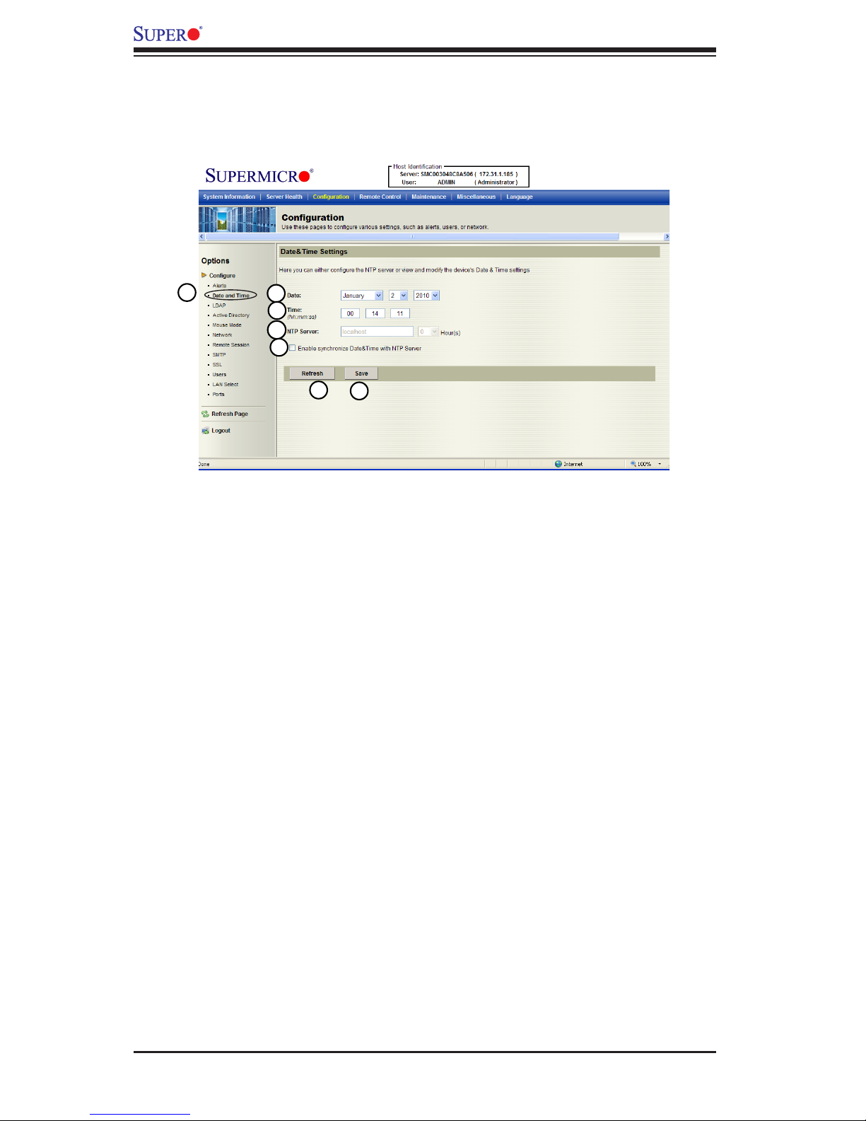
2.4.2 Conguration - Time and Date Settings
This feature allows the user to congure time and date settings for the host server
and client computer. When you click <Time and Date> in the Options window, the
following screen will display.
1. Time and Date: Click this item to congure the <Time and Date> settings.
2. Date: Enter month, date and year in this row.
3. Time: Enter hour, minute and second in the (hh:mm:ss) format.
4. NTP Server: Enter the name of the NTP server in this eld.
5. Enabling Synchronizing: Check this box to enable synchronization of time and
date of the client computer with the NTP server.
6. Refresh: Click this button to refresh the page.
7. Save: Click this item to save any changes done to the Time and Date set-
tings.
1
2
3
5
6
7
4
Page 29

Chapter 2: Conguring BMC/IPMI Settings
2-19
2.4.3 Conguration - Light-Weight Directory Access Protocol
(LDAP) Settings
This feature allows the user to congure Light-Weight Directory Access Protocol
(LDPA) settings. When you click <LDAP> in the Options window (1), the following
screen will display.
Examples and Explanations of the LDAP settings are shown below:
1. Port: 389-This item indicates the port number of the LDAP server.
2. IP Address: xx.xx.xx.xx- This item indicates the IP address of the LDAP
server.
3. Bind Password: Secret- This item indicates the password of the LDAP server.
4. Bind DN: cn=manager, dc=administrator, dc=com- The bind DN is the user or
the LDAP server that is allowed to do limited search in the LDAP directory.
5. SearchBase: dc=administrator, dc=com-This feature shows the client which
port in the external directory tree to use for doing search.
After entering the information in the elds, click <Save> to save the information
you've just entered.
1
2
3
5
4
Page 30
2-20
Embedded BMC/IPMI User's Guide
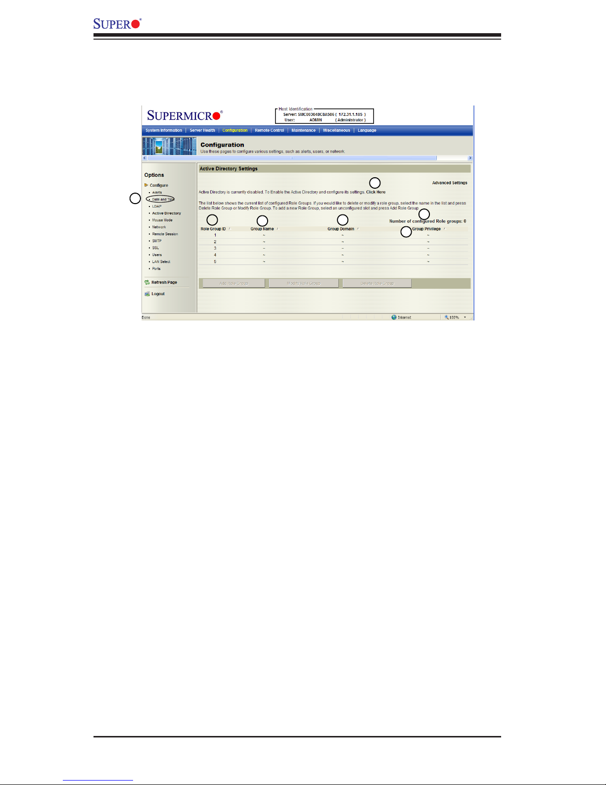
2.4.4 Conguration - Active Directory Settings
This feature allows the user to congure Active Directory settings. When you click
<Active Directory> in the Options window, the following screen will display.
1. Active Directory: Click this item to congure Active Directory settings.
2. If Active Directory is currently disabled, click <Click Here> to enable it.
3. Number of Congured Role Group: This item displays the number of cong-
ured role groups.
4. Role Group ID: This item displays the role group ID.
5. Group Name: This item displays the name of the role group.
6. Group Domain: This item displays the domain of the role group.
7. Group Privilege: This item displays the user privilege of the role group.
1
2
3
4
5
6
7
Page 31

Chapter 2: Conguring BMC/IPMI Settings
2-21
2.4.4.a Conguration - Active Directory - Advanced Settings
This feature allows the user to congure Active Directory-Advanced settings. When
you click <Active Directory> in the Options window and checked the Enable box
indicated on the previous page, the following screen will display.
1. Active Directory: Click this item and check the Enable box on the previous page
to congure Active Directory settings.
2. Check the Enable box to enable Active Directory Authentication.
3. User Domain Name: This item allows the user to enter the user domain
name.
4. Time Out: This item displays the Time-out settings.
5. Domain Controller Server Addresses 1~3: These items allow the user to enter
the IP addresses for the Domain Controller Servers 1~3.
6.DefaultActiveDirectoryCerticate: This item displays the information of the
default active directory certicate.
7. Upload New Default Active Directory Certicate: Click <Browse> to select
and upload the new default active directory certicate.
After the required information is entered, click <Save> to save the information you've
entered or click <Cancel> to cancel it.
5
6
7
1
2
3
4
Page 32

2-22
Embedded BMC/IPMI User's Guide
2.4.5 Conguration - Mouse Mode
This feature allows the user to congure mouse mode settings. When you click
<Mouse Mode> in the Options window, the following screen will display.
1. Mouse Mode: Click this item to congure the mouse mode settings.
2. Set Mode to Absolute: Check this radio button to use the Absolute mode for
the Windows OS. (This is the default setting.)
3. Set Mode to Relative: Check this radio button to use the Relative mode for
the Linux/Unix OS.
Note: IPMI is an OS-independent platform, and KVM support is an added
feature for IPMI. For your mouse to function properly, please congure the
Mouse Mode settings (above) according to your OS type.
1
2
3
Page 33

Chapter 2: Conguring BMC/IPMI Settings
2-23
2.4.6 Conguration - Network Settings
This feature allows you to congure network settings. When you click <Network>
in the Options window, the following screen will display.
1. Network: This item allows you to view or modify network settings.
2. MAC Address: Enter the MAC address for your network.
•Check the rst radio button to obtain an IP address automatically by using DHCP
(Dynamic Host Conguration Protocol).
•Check the second radio button to use the IP address entered below.
3. IP address: If the second radio button above is checked, enter your IP ad-
dress in the box.
4. Subnet Mask: Enter the address for the subnet mask of your network.
5. Default Gateway: Enter the IP address for the default gateway of your net-
work.
6. Primary DNS Server: Enter the IP address of your primary domain name
server.
7. Secondary DNS Server: Enter the IP address of your secondary domain
name server.
8. Enable VLAN: Check this box to enable Virtual LAN support
9. VLAN Tag: This item allows you to use VLAN Tagging or Frame Tagging
to encapsulate specic data, so it can be transparently transmitted through
multiple platforms without leaking any information. After conguring network
settings, click <Save> to save the conguration.
1
2
3
5
6
7
8
9
4
Page 34

2-24
Embedded BMC/IPMI User's Guide
2.4.7 Conguration - Remote Session
This feature allows the user to congure remote session settings. When clicking
<Remote Session> in the Options window, the following screen displays.
1. Virtual Media Attach Mode: Click the pull-down menu to display virtual media
attach modes.
•Attach: Select this mode to activate a virtual media to make it available for
remote access. A virtual device will always be seen in the system BIOS even
when it is not active.
•Auto Attach (Default): Select this mode to automatically enable virtual media
support and make it available for remote access. Virtual devices will only be
shown in the operating systems and BIOS when a device or an ISO image is
connected through the virtual media wizard.
•Detach: Select this mode to disable virtual media for remote access.
2. Floppy Emulation: Click the pull-down menu to see the following:
•Off (Default): Select this item to disable oppy emulation when you wish to con-
nect the USB Flash drive via virtual media redirection.
•On: Select this item to enable oppy emulation when you wish to connect a
oppy drive or oppy ISO image through virtual media redirection.
Warning: Be sure to close all Java sessions before changing oppy emula-
tion to avoid unexpected errors.
1
2
3
Page 35

Chapter 2: Conguring BMC/IPMI Settings
2-25
2.4.8 Conguration - SMTP Settings
This feature allows the user to congure SMTP (Simple Mail Transfer Protocol)
settings for email transmission through the network. When you click <SMTP> in
the Options window, the following screen will display.
1. SMTP: Check this item to congure SMTP (Simple Mail Transfer Protocol)
settings for email transmission across the IP network.
2. Mail Server IP: Enter the SMTP Mail Server IP address for your network in
the box.
3. Mail Sender Address: Enter the mail sender address that you would like the
alert to show as "sent from."
4. Mail Server Port: Enter the mail server port number. The default port is 25 for
most servers.
5. Save: Click this item to save any changes to the SMTP setting.
1
2
3
5
4
Page 36
2-26
Embedded BMC/IPMI User's Guide
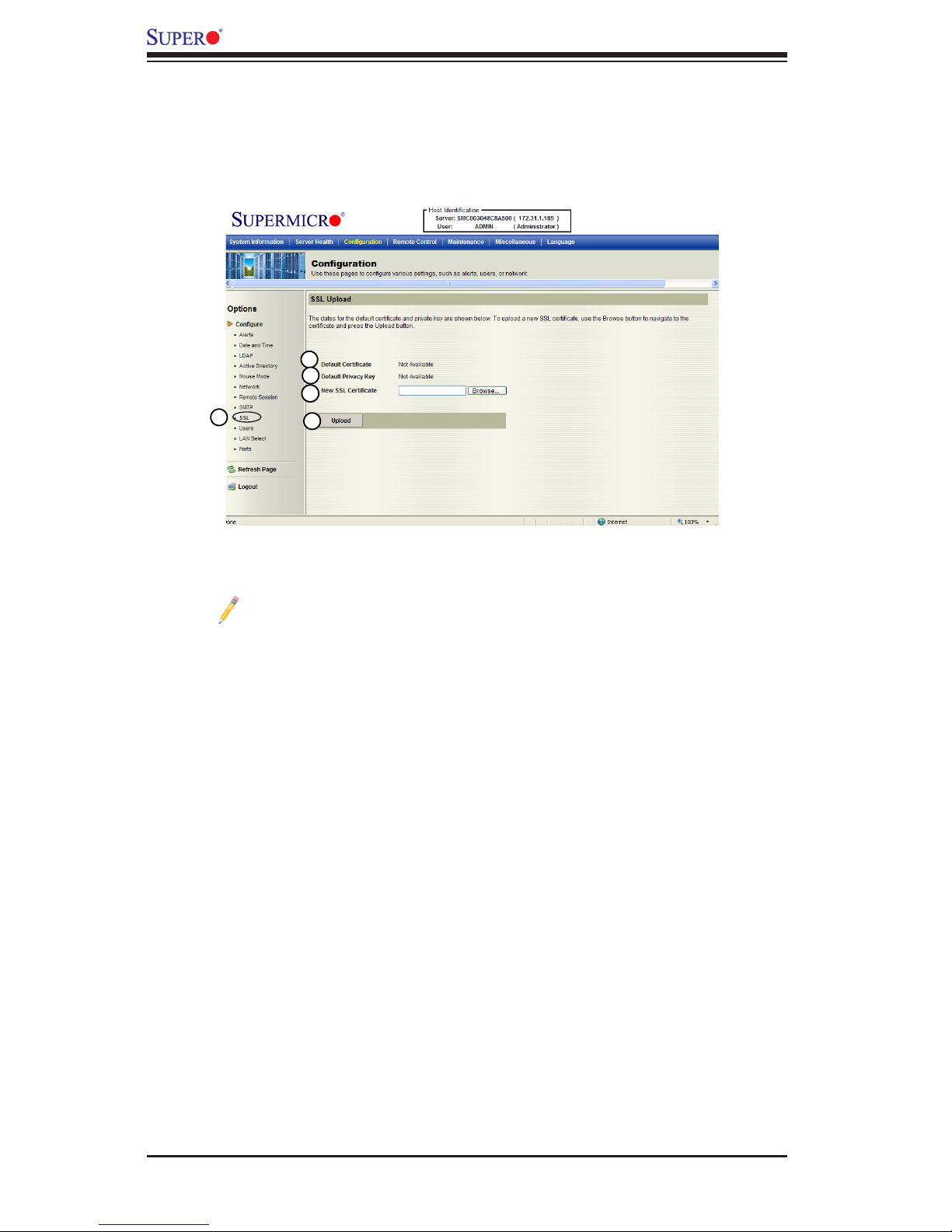
2.4.9 Conguration - SSL Upload Settings
This feature allows the user to congure upload settings for encrypted data to trans-
mit across the internet by using the Secure Sockets Layer (SSL) protocol. When you
click <SSL Upload> in the Options window, the following screen will display.
1. SSL: Check this item to congure SSL Upload settings for the encrypted data
to securely transmit through the internet.
Note: SHA2 and RSA 2048 bit SSL supported
2. Default Certicate: This item allows the user to enter the default certicate
information. Once entered, it will display the default certicate information.
3. Default Private Key: This item allows the user to enter the default private key
information. Once entered, it will display the default private key information.
4. New SSL Certicate: This item allows the user to enter the new SSL Certi-
cate information.
5. Upload: Click this button to upload encrypted data to the network for trans-
mission.
1
2
3
5
4
Page 37
Chapter 2: Conguring BMC/IPMI Settings
2-27
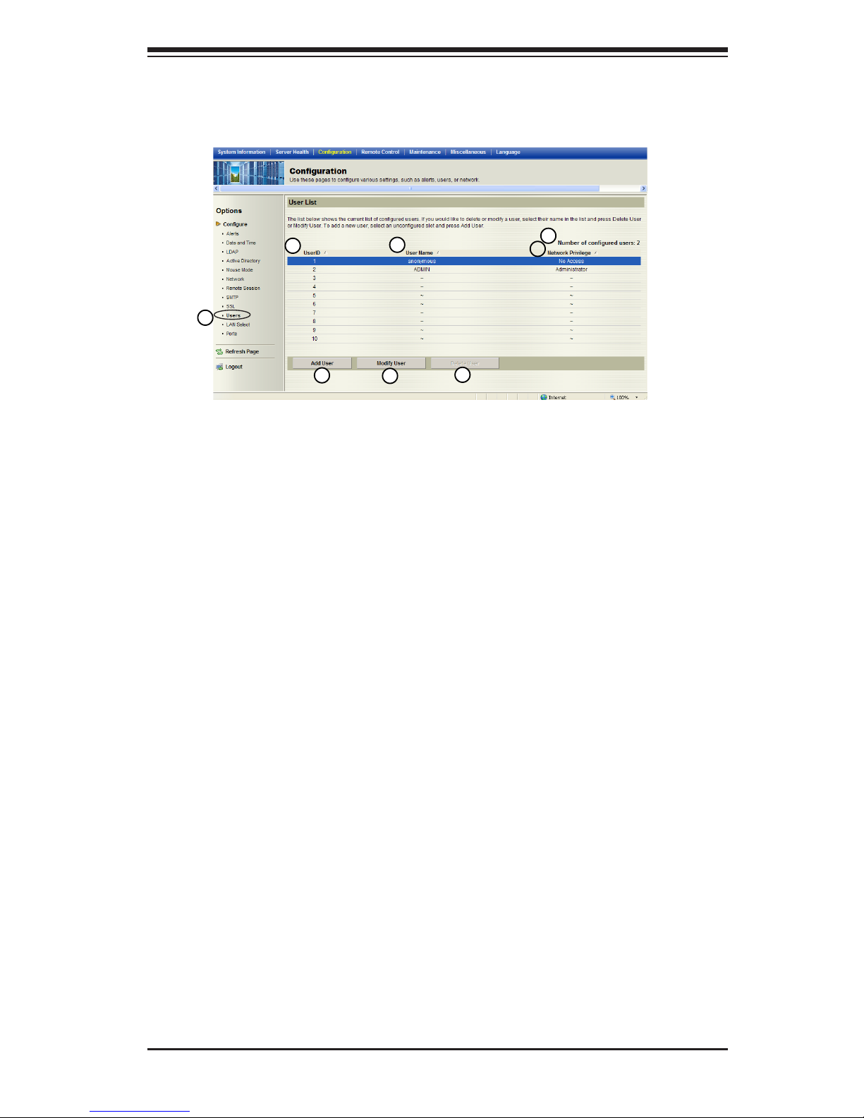
2.4.10 Conguration - Users Settings
This feature allows you to change users settings. When you click <Users> in the
Options window, the following screen will display.
1. Users: Select this item to congure the user settings. The current users list is
displayed.
2. User ID: This item displays the ID of a user.
3. User Name: Use this item to enter and display a user name.
4. Network Privileges: Use this item to set the network access privileges for a
user.
•Privileges for an Administrator: An administrator has full privileges in accessing,
controlling and managing the network, including creating accounts for users and
changing network conguration settings.
•Privileges for an Operator: An operator has limited access to the network to
perform tasks that have been pre-assigned or approved by the Administra-
tor. He/she is not allowed to issue commands or modify network settings, for
example.
5. Number of congured users: This item displays the number of the users that
are set up for the network. The maximum of 16 user proles can be made.
6. Add User: Click this item to add a new user to the network. When prompted,
using the arrow keys, select a user from the users list to add the user infor-
mation.
7. Modify User: Click this item to modify the information or the status of a user.
8. Delete User: Click this item to delete a user from the network.
6
7
8
1
2
3
4
5
Page 38

2-28
Embedded BMC/IPMI User's Guide
2.4.11 Conguration - LAN Select
This feature allows you to select LAN ports. When you click <LAN Select> in the
Options window, the following screen will display.
1. LAN Select: This item allows the user to select the LAN port for IPMI com-
munication.
2. Enable: Click <Enable> to enable LAN Port Select support.
•Dedicated LAN: Select this item to direct all IPMI communication to the IPMI
Dedicated LAN port.
•Onboard LAN: Select this item to direct all IPMI communication to an onboard
LAN port.
3. Set: Click <Set> to use the port you've selected for IPMI communication.
1
2
3
Page 39

Chapter 2: Conguring BMC/IPMI Settings
2-29
2.4.12 Conguration - Ports
This feature allows you to change LAN Port settings. When you click <Ports> in
the Options window, the following screen will display.
1. Ports: This item allows you to the following LAN port settings.
2. Video: Enter a proper setting for video display. (Default: 5901)
3. HID: Enter a proper HID setting. (Default: 5900)
4. CD: Enter a proper CD setting. (Default: 5120)
5. Http: Enter the Http address. (Default: 80)
6. Click <Save> to save IPMI LAN port settings.
Port 5123 is used for oppy and Port 623 is used for IPMI. All ports are UDP
ports.
Note: If the rewall is enabled, please allow exceptions for these ports so
that BMC can work properly.
1
2
3
6
5
4
Page 40

2-30
Embedded BMC/IPMI User's Guide
2.5 Remote Control - the Main Menu
This section allows the user to carry out activities and perform operations on a
remote server via remote access.
This submenu allows you to congure the remote control settings.
1. Remote Control: Click this item to congure Remote Control settings.
2. Launch Console: Click this button to launch Remote Console via Java or IE.
3. Launch SOL: Click this button to enable Serial_Over_LAN support.
4. Power Control: Click this button to display server power state and to congure
server power settings.
5. Virtual Media: Click this button to congure virtual media settings.
6. Refresh: Click this button to refresh the page.
2
3
1
5
6
4
Page 41

Chapter 2: Conguring BMC/IPMI Settings
2-31
2.5.1 Remote Console
This feature allows you to perform various activities on the server. When you
click <Remote Console> in the Options window, the following Remote Control
submenu screen will display.
Follow the instructions below to launch the remote console.
1. Remote Control: Check this item to enable remote console support and man-
age the server from a remote site via Java or Active X (for Internet Explorer).
2. Launch Console: Click this button to launch the remote console via the Java
script.
3. Java Starting: Upon launching the remote console, a screen will display indi-
cating that Java is starting.
After the remote console is launched, the screen of the client system will display
as shown below.
1
2
3
Page 42

2-32
Embedded BMC/IPMI User's Guide
2.5.1.1 Remote Console - Video
This feature allows you to congure video settings for your remote console. When
you click <Video> in the Menu bar, the video settings of the remote console will
display as shown below.
1. Video: Click this item to congure and manage the video settings of a server
on a remote site via the Remote Console.
2. Video Options: The pull-down submenu contains the options listed below.
•Pause: Click this item to freeze the screen.
•Resume: Click this item to re-activate a frozen screen.
•Refresh: Click this item to refresh the system.
•Capture Current Screen: Click this item to capture the current screen display.
•Full Screen: Click this item to use the full screen mode.
•Exit: Click this item to exit the Remote Console.
1
2
Page 43

Chapter 2: Conguring BMC/IPMI Settings
2-33
2.5.1.2 Remote Console - Keyboard
This feature allows you to congure keyboard settings for your remote console.
When you click <Keyboard> in the Menu bar, the keyboard settings of the remote
console will display as shown below.
1. Keyboard: Click this item to congure and manage the keyboard settings of a
remote server via the Remote Console.
2. Options: The pull-down submenu contains the options listed below.
•Hold Right Alt Key: Check this item to emulate the right alt key when it is
pressed.
•Hold Left Alt Key: Check this item to emulate the left alt key when it is
pressed.
•Left Windows Key: Click this item to display the Left Window Key submenu as
follows:
•Hold down: Check this item to emulate the left window key when pressed.
•Press and Release: Click this option to press and release the left window key.
Right Windows Key: Click this item to display the Right Window Key submenu as
follows:
•Hold down: Check this item to emulate the right window key when pressed.
•Press and Release: Click this option to press and release the right window
key.
1
2
Page 44

2-34
Embedded BMC/IPMI User's Guide
3. Macros: Click this item to display and to use the hot keys listed in its pull-
down submenu.
4. From the Macro pull-down menu select a hot key to use.
•Ctrl+Alt+Del
•Alt+Tab
•Alt+Esc
•Ctrl+Esc
•Alt+Space
•Alt+Enter
•Alt+Hyphen
•Alt+F4
•Alt+PrntScrn (Print Screen)
•PrntScrn
•F1
•Pause
5. Keyboard pass-through: Click this item (1) to use your local keyboard for the
remote console.
Note: Keyboard Pass-through provides full keyboard support. It sends all
keys, including special key combinations to the host server.
1
2
Page 45

Chapter 2: Conguring BMC/IPMI Settings
2-35
6. Soft Keyboard: Select the item Soft Keyboard to use soft keyboard for the
remote console as shown below.
1. Language: From the pull down menu, select the following language settings:
English (United States), English (United Kingdom), Japanese, and Germany.
2. Modier Key: Click a button to select the soft keyboard mode.
•Combination: Click the button to use a special key combination as a single
key.
•Single Key
•Lock: Click this button to lock the key combination you've created.
1
2
Page 46

2-36
Embedded BMC/IPMI User's Guide
2.5.1.3 Remote Console - Mouse
This feature allows you to congure the mouse settings for your remote console.
To congure the mouse settings, follow the instructions below.
Click <Mouse> in the menu bar, select an item from the pull-down submenu as
shown below.
1. Synchronize Mouse Cursor Alt+M: Click this item (or press <Alt> and <M>
keys simultaneously) to synchronize your local mouse cursor and the mouse
cursor of your remote console.
2. Show Cursor: Click this item to display the cursor on the screen.
1
2
Page 47

Chapter 2: Conguring BMC/IPMI Settings
2-37
2.5.1.4 Remote Console - Media
This feature allows you to congure media virtualization settings for your remote
console.
1. Click <Media> in the Menu bar to invoke the Media page as shown above.
2. Virtual Media Wizard: click this item to launch the Virtual Media Wizard, which
allows you to congure Virtual Media settings as shown on the next page.
1
2
Page 48

2-38
Embedded BMC/IPMI User's Guide
Virtual Media
1. Floppy/USB Key Media: This item allows the user to congure the Floppy/
USB Key Media settings. The sub-items include the following.
• Floppy Image
•A (Disk Drive A of the remote console)
•Browse: Click Browse to select the location of the Floppy ISO image.
2. Connect Floppy: After selecting the Virtual Media for your Remote Console,
click <Connect Floppy> to connect to the remote console via the Floppy drive
you chose.
3. CD Media: This item allows the user to congure CD Media settings. The
sub-items include the following.
• ISO Image
•<Drive letter> (CD/DVD Drive)
•Browse: Click <Browse> to select the location of the CD/DVD ISO image.
4. Connect CD/DVD: After selecting the Virtual Media for your Remote Console,
click <Connect CD/DVD> to connect to the remote console via the CD/DVD
you chose.
5. Status: This window displays the status of the target drive of the remote
console.
4
5
3
1
2
Page 49

Chapter 2: Conguring BMC/IPMI Settings
2-39
2.5.3 Remote Control-Launch SOL
This feature allows you to launch the remote console by using Serial_over_LAN.
Follow the instructions below to launch SOL.
1. Launch SOL: Click this item to access a host server via Console Redirection.
It also allows a system administrator to monitor and manage a server from a
remote site.
1
2
Page 50

2-40
Embedded BMC/IPMI User's Guide
Launching SOL
1. Security Warning: Once you've launched SOL, a security warning will appear,
indicating that the application's digital signature cannot be veried
2. Always trust content from this publisher: Click this item to give full access to
this program, eliminating further security warnings.
3. Click <Run> to continue launching SOL. If you continue with SOL launching,
the following screen will appear.
4. Click <Baud Rate> to invoke the submenu, which will allow you to select the
Baud Rate for serial line transfer.
5. Baud Rate (bps): You can select a Baud rate from the list as your SOL trans-
fer rate. The options are: 9600 bps (bit-per-second), 19200 bps, 38400 bps,
57600 bps, 115200 bps, and default. Make sure that the Baud Rate selected
here matches the Baud Rate set in the BIOS. Then, click <Start> to start the
session or press <Stop> to abort the SOL session.
4
1
2
3
5
Page 51
Chapter 2: Conguring BMC/IPMI Settings
2-41
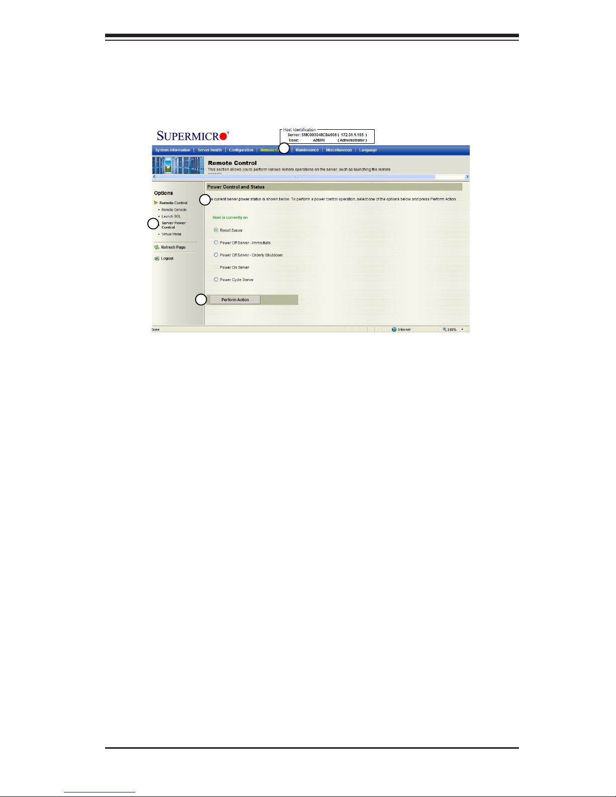
2.5.3 Server Power Control
This feature allows you to congure power management settings for your remote
console. To congure Server Power Control settings, follow the instructions be-
low.
1. Click <Remote Control> in the Menu bar to invoke the Remote Control Main
Page.
2. Click <Server Power Control> to display the Power Control submenu as
shown above.
3. Power Control and Status: This submenu indicates the status and the current
power control settings of the remote server. The status of the remote server
are displayed as below:
•Reset Server: Click this radio button to reset the power control settings for the
remote server.
•Power Off Server - Immediately: Click this radio button to immediately power
off the remote server.
•Power Off Server - Orderly Shutdown: Click this radio button to power off and
shut down the remote server in an orderly manner.
•Power On Server: Click this radio button to power on the remote server.
•Power Cycle Server: Click this radio button to power cycle the remote server.
4. Perform Action: After selecting a power setting from the list above, click this item
to execute the command and perform the action.
3
1
2
4
Page 52

2-42
Embedded BMC/IPMI User's Guide
2.6 Maintenance
Use this feature to manage and congure IPMI devices. Follow the instructions
below to congure Maintenance settings.
1. Click <Maintenance> in the Menu bar to display the Maintenance page.
2. Click <Firmware Update> to update the BMC rmware (the BIOS) of the
remote server. The Firmware Update screen is shown in the next section.
3. You can also press <Unit Reset> to reboot the BMC (IPMI) Controller.
1
2
3
Page 53
Chapter 2: Conguring BMC/IPMI Settings
2-43
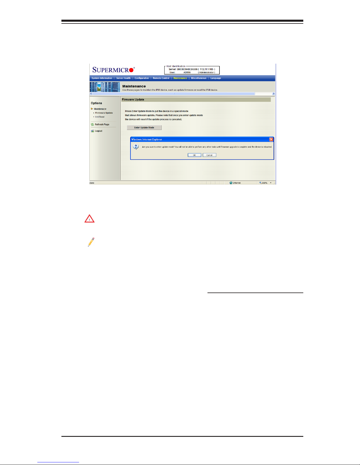
2.6.1 Maintenance - Firmware Update
When you click <Maintenance> in the Menu bar, the Maintenance Main page will
display as below.
Firmware Update
Enter Update Mode: Click this item to enter the update mode.
Warning: Once you've entered the rmware update mode, the device will
be reset even if you cancel the process of rmware updating.
Notes:
1. When updating rmware, you are given the option to "Preserve Con-
guration." Uncheck this option to load the factory default settings, and all
the conguration settings will be lost.
2. If you are using the Static IP mode, it is not recommended to uncheck
"Preserve Conguration," since it will reset the network settings to the
DHCP (Dynamic Host Conguration Protocol) mode.
Page 54
2-44
Embedded BMC/IPMI User's Guide
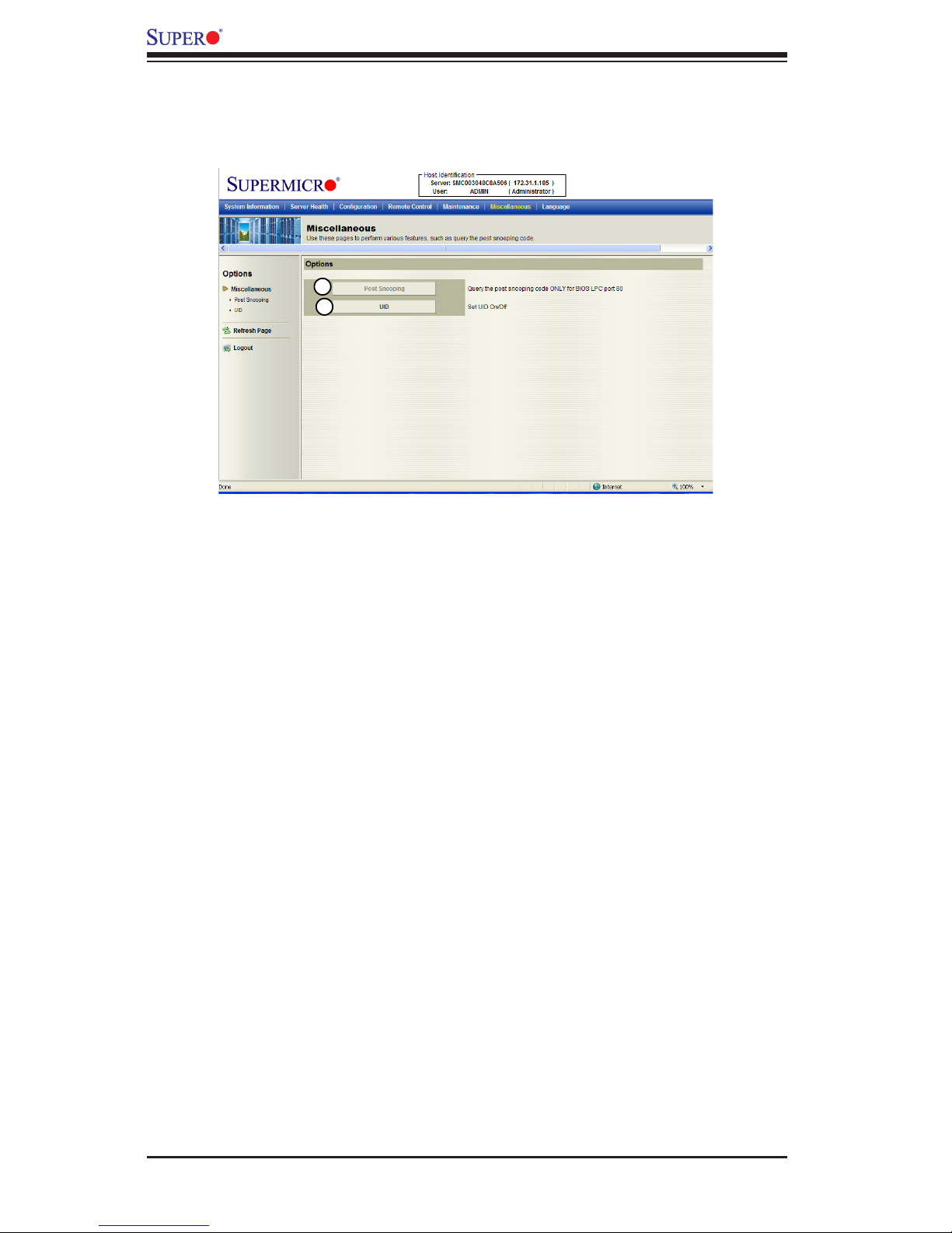
2.7 Miscellaneous
This feature allows the user to perform network activities. Click <Miscellaneous> in
the Menu bar to display the Miscellaneous page.
Miscellaneous
1. Post Snooping: Click this item to query the POST (Power_On_Selt-Test)
Snooping code for BIOS LPC Port80.
2. UID: Click this item to enable or disable UID (unit identication) support as
shown on the next page.
1
2
Page 55

Chapter 2: Conguring BMC/IPMI Settings
2-45
2.7.1 Miscellaneous - UID (Unit Identication)
This feature allows the user to enable or disable UID support. Click <Miscellaneous>
in the Menu bar to display the Miscellaneous page.
Miscellaneous - UID
1. This item shows the current UID status.
2. This item allows the user to enable or disable UID support for console redi-
rections.
After clicking the enable UID button or disable UID button, click <Set> to it to take
effect.
1
2
Page 56

2-46
Embedded BMC/IPMI User's Guide
2.8 Language
This feature allows you to congure Language Settings for your IPMI connections.
Follow the instructions below to congure the language settings.
Language Settings
1. Click <Language> in the Menu bar to display the Language page as shown
above.
2. From the Available Languages submenu select a language setting for your
remote console. (Currently, English is the language available for this utility.)
1
2
Page 57

3-1
Chapter 3: Troubleshooting
Chapter 3
Frequently Asked Questions
3-1 Frequently Asked Questions
A.Questions:HowdoIashtheIPMIrmware?
Answer:
1. Log in the IPMIcfg utility by entering the system IP address.
2. Click the <Maintenance> button. Browse the les to select a correct le to
ash the rmware.
3. Click the <Update Firmware> button to proceed with rmware ashing.
B. Questions: How do I set up the IP address and MAC address for remote
access?
Answer:
1. Boot the system into DOS.
2. Run the utility-IPMICFG from DOS.
3. Follow the prompts to set up the IP address and MAC address for remote
access.
You can also go to the BIOS to congure the IP address.
Page 58

Embedded BMC/IPMI User's Guide
3-2
Notes
Page 59

A-1
Appendix A: Flash Tools
Appendix A
Flash Tools
A-1 Overview
This chapter provides instructions on how to use AMI Flash Tools. The Flash Tools
allow the user to use Command_Line (CL) utility programs to upgrade or update
rmware via different channels such as KCS, USB and LAN connections. We are
going to focus on the following tools in this manual.
1. YAFUFlash
2. YAFUKCS
•YAFUFlash
YAFUFlash (Yet Another Firmware Upgrade Flash) allows the user to ash the BMC
in both Linux and Windows environments via network or USB connections. You can
choose to use network connections or USB connections to ash the BMC based
on how you use the ash tools.
•YAFUKCS
YAFUKCS (Yet Another Firmware Upgrade Keyboard Controller Style) is used to
ash the rmware in the DOS environment via the KCS (Keyboard_Controller_Style)
interface.
A-2 Flashing the BMC Firmware in the DOS
Environment
YAFUKCS is the tool used to ash the BMC rmware in DOS through the KCS
interface. To ash the BMC, follow the instructions below:
1. Copy yafukcs.exe into your DOS machine.
2. Run the yafukcs utility.
3. Use the settings as listed below.
Page 60

Embedded BMC/IPMI User's Guide
A-2
•Format:
Yafukcs [OPTION] [FW_IMAGE_FILE]
[OPTIONS]
Options Commands
-info This option displays information regarding existing and current rmware.
-auto This option allows for automatic upgrades by comparing ash module headers.
-full This options allows for full upgrades.
-force-boot Select this option to force the boot loader to be upgraded during full upgrade. The
boot loader is "preserved" by default.
-c This option preserves conguration modules during full upgrade.
[FW_IMAGE_FILE]
The rmware-image le name is [rom.ima].
Examples
•Example 1
/Yafukcs -info rom.ima
Description: This command displays the details of both existing and new rm-
ware.
•Example 2
/Yafukcs -full rom.ima
Description: This command starts ashing the new rom.ima to the rmware.
•Example 3
/Yafukcs -full -force-boot rom.ima
Description: This command starts ashing the new rom.ima to the rmware using
"FORCE BootLoader upgrade."
A-3 Flashing the BMC Firmware in the Windows
Environment
YAFUFlash is used to ash the BMC rmware in Windows through USB or Network
connections. To ash the BMC in Windows, follow the instructions below.
1. Open Command Prompt. Go to YafuFlash\Windows\path.
2. The following two les will be displayed:
Page 61

A-3
Appendix A: Flash Tools
•Yafuash.exe
•LIBIPMI.dll
3. Run "Yafuash.exe" in the command prompt.
4. Use the settings as listed below.
•Format:
Yafuash [OPTION] [MEDIUM] [FW_IMAGE_FILE]
[OPTIONS]
Options Commands
-info This option displays information regarding existing and new rmware.
-auto This option allows for automatic upgrades by comparing ash module headers.
-full This options allows for full upgrades.
-force-boot Select this option to force the boot loader to be upgraded during full upgrade. The
boot loader is "preserved" by default.
-c This option preserves conguration modules during full upgrade.
[MEDIUM]
Medium Options
-cd Select this option to use USB connections.
-nw & ip Select this option to use network with -ip (followed by the IP address).
[FW_IMAGE_FILE]
The rmware-image le name is [rom.ima].
Examples
Using Network as a Medium
•Example 1
Yafuash -nw -ip 155.166.132.12 -info rom.ima
Description: This command displays the details of both existing and new rmware
using the network connection with the ip address of 155.166.132.12.
•Example 2
Yafuash -nw -ip 155.166.132.12 -full rom.ima
Description: This command starts ashing the new rom.ima to the rmware using
the network connection with the IP address of 155.166.132.12.
Page 62

Embedded BMC/IPMI User's Guide
A-4
•Example 3
Yafuash -nw -ip 155.166.132.12 -full -force-boot rom.ima
Description: This command starts ashing the new rom.ima to the rmware with
FORCE BootLoader Upgrade via the network connection using the IP address
of 155.166.132.12.
Using USB as a Medium
•Example 1
Yafuash -cd -info rom.ima
Description: This command displays the details of both existing and new rmware
using a USB connection.
•Example 2
Yafuash -cd -full rom.ima
Description: This command starts ashing the new rom.ima to the rmware us-
ing a USB connection.
•Example 3
Yafuash -cd -full -force-boot rom.ima
Description: This command starts ashing the new rom.ima to the rmware with
FORCE BootLoader Upgrade using a USB connection.
Page 63

A-5
Appendix A: Flash Tools
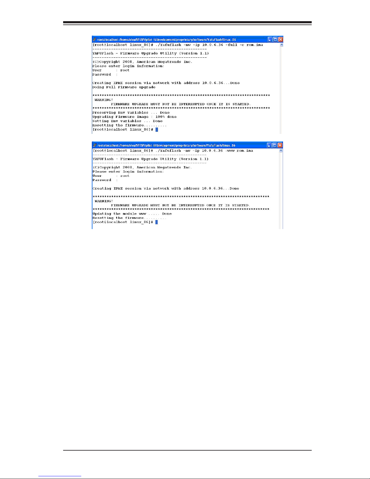
A-4 Flashing the BMC Firmware in the Linux
Environment
YAFUFlash is used to ash the BMC rmware in the Linux environment using
network or USB connections. To ash the BMC in Linux, follow the instructions
below.
1. Open the Terminal. Go to YafuFlash/Linux path.
2. The le libipmi.so 1 should be accessible to a Linux system. Usually when
running an application, Linux will search for a le in dependent libraries in
default locations, such as usr/lib/lib folders.
3. Copy libipmi.so.1 to /lib or /usr/lib. Run "1dcong"
or
Copy libipmi.so.1 to a folder and issue the following command:
#LD_LIBRARY_PATH=<location_of_libipmi_so>/Yafuash
Note: You may have to create a link to libipmi.so.1.0 (ln-sf libipmi.so.1.0
libipmi.so.1).
4. Run "Yafuash.exe" in the terminal.
5. Use the settings as listed below.
•Format:
/Yafuash [OPTION] [MEDIUM] [FW_IMAGE_FILE]
[OPTIONS
Options Commands
-info This option displays information regarding existing and new rmware.
-auto This option allows for automatic upgrades by comparing ash module headers.
-full This options allows for full upgrades.
-force-boot Select this option to force the boot loader to be upgraded during full upgrade. The
boot loader is "preserved" by default.
-c This option preserves conguration modules during full upgrade.
[MEDIUM]
Medium Options
-cd Select this option to use USB connections.
-nw & ip Select this option to use network with -ip (followed by the IP address).
Page 64

Embedded BMC/IPMI User's Guide
A-6
[FW_IMAGE_FILE]
The rmware-image le name is [rom.ima].
Examples
Using Network as a Medium
•Example 1
/Yafuash -nw -ip 155.166.132.12 -info rom.ima
Description: This command displays the details of both existing and new rmware
using the network connection with the IP address of 155.166.132.12.
•Example 2
/Yafuash -nw -ip 155.166.132.12 -full rom.ima
Description: This command starts ashing the new rom.ima to the rmware using
the network connection with the IP address of 155.166.132.12.
•Example 3
/Yafuash -nw -ip 155.166.132.12 -full -force-boot rom.ima
Description: This command starts ashing the new rom.ima to the rmware with
FORCE BootLoader Upgrade via the network connection using the IP address
of 155.166.132.12.
Using USB as a Medium
•Example 1
/Yafuash -cd -info rom.ima
Description: This command displays the details of both existing and new rmware
using a USB connection.
•Example 2
/Yafuash -cd -full rom.ima
Description: This command starts ashing the new rom.ima to the rmware us-
ing a USB connection.
•Example 3
/Yafuash -cd -full -force-boot rom.ima
Description: This command starts ashing the new rom.ima to the rmware with
FORCE BootLoader Upgrade using a USB connection.
Page 65
A-7
Appendix A: Flash Tools
A-5 Firmware Recovery
If the rmware upgrade is interrupted during rmware ashing, please follow the
steps listed below for rmware recovery using Yafukcs.
1. Power off the system by disconnect the power cord.
2. Boot to DOS and ash the rmware using Yafukcs.
Page 66

Embedded BMC/IPMI User's Guide
A-8
Notes
Page 67

The products sold by Supermicro are not intended for and will not be used in life support systems, medical equipment, nuclear facilities or systems, aircraft, aircraft devices,
aircraft/emergency communication devices or other critical systems whose failure to perform be reasonably expected to result in signicant injury or loss of life or catastrophic
property damage. Accordingly, Supermicro disclaims any and all liability, and should buyer use or sell such products for use in such ultra-hazardous applications, it does so
entirely at its own risk. Furthermore, buyer agrees to fully indemnify, defend and hold Supermicro harmless for and against any and all claims, demands, actions, litigation, and
proceedings of any kind arising out of or related to such ultra-hazardous use or sale.
(Disclaimer Continued)
 Loading...