

Page 1
1.0
®
SUPER
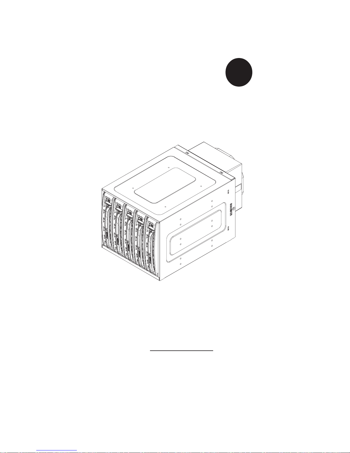
USER'S GUIDE
Mobile Rack
CSE-M35S/CSE-M35T1
Page 2

SUPER CSE-M35S/CSE-M35T1 User's Guide
2
Table of Contents
1. Packaging List ......................................................................................................3
2. Technical Specifications .................................................................................... 4
3. Jumper Settings...................................................................................................5
4. Installation Procedures ..................................................................................... 7
Page 3

3
CSE-M35S/CSE-M35T1
Supermicro’s CSE-M35S/CSE-M35T1 Mobile Rack Series offers the cutting
edge technology with greater flexibility. The CSE-M35T1 supports five Serial ATA hot-swappable hard drives that yield a unparalleled storage capacity without compromising productivity by eliminating possible system downtime. The CSE-M35S also accommodates five SCSI SCA 320/160 Hard
drives which provide configuration flexibility and maximum data integrity.
1. Packing List
Please check to see if you have received all the items listed below:
*CSE-M35S/CSE-M35T1 Mobile Rack
*90mm-Exhaust Fan (Fan-0057)
*Screws: Thirteen (13) counts of Flat Head Screws
Twenty-four (24) counts of Round Head Screws
Seven (7) counts of Round Head Screws with Lock-Washer
*Drive Carrier Five (5)CSE-PT17/CSE-PT17(B)(-black)
(*For CSE-M35T1 only)
*Serial ATA Backplane (CSE-SATAM35)
*Five (5) Serial ATA Cables (CBL-0044)
*Serial ATA LED cable (CBL-0057)
Packing List
*SCSI cable (CBL-027-U320)
*SCSI Backplane (CSE-SCAM942)
(*For CSE-M35S only)
Page 4

SUPER CSE-M35S/CSE-M35T1 User's Guide
4
2. Technical Specifications
Occupancy Three (3) 5.25" Drive Bays
Capacity Five (5) 1" SCA Ultra320/160 Hard Drives with
SAF-TE built-in (*CSE-M35S only)
Five (5) 1" Host Receptacle Connectors, SATA
hot-swap hard drives (*CSE-M35T-1 only)
Cooling
Subsystem
One (1) 90mm (9cm) Exhaust Fan
System
Monitoring
*Fan Fail Detection LED and Alarm
*Overheat LED indication
*Drive Fail Alarm and Indication (*CSE-M35S
only)
*Built-in Termination (*CSE-M35S only)
Dimension
(WxHxD)
146mm x 129mm x 245mm
(5.7 in x 5.0 in x 9.6 in)
Weight Net: 5.9lb (2.9 kg), Gross: 7.5lb (3.7 kg)
Chassis supported:
SC762, SC830, SC942
Page 5

5
3. Jumper Settings
A. Jumper Settings for the CSE-M35S (SCSI):
Location of Jumpers
Jumper Description Setting
JP18 Buzzer Reset Closed: Enable,
Open: Disable (*Default)
JP21 SCSI Termination Closed: Enable (*Default),
Open: Disable
JP24 SCSI ID Selection 1-2: SCSI Ids: 0,1,2,3,4 (*Default),
2-3: SCSI Ids: 9,10,11,12,13
JP29 GEM 318 IDs 1-2: ID6 (*Default),
2-3: ID8
JP30 Fan Sense Pins 1-2: Enable (*Default) (If a fan
is not present, the alarm will
sound.),
Pins 2-3: Disable
Jumper Settings
J
P29
JP21
JP30
JP18
JP24
Pin 1
Pin 1
Pin 1
Pin 1
Pin 1
Page 6

SUPER CSE-M35S/CSE-M35T1 User's Guide
6
B. Jumper Settings for the CSE-M35T1 (SATA):
Location of Jumpers
JP28
JP25
JP18
C
hannel #1
Channel #2
ACT5
FAN
Channel #3
Channel #4
Channel #5
ACT6
ACT7
ACT8
ACT1
ACT2
ACT3
ACT4
COM
Pin 1
Pin 1
Key
JP26
Activity LEDs-
Pin Definitions
Act. LED 1
Act. LED 2
Act. LED 3
Act. LED 4
Act. LED 5
Channe l 1
Channe l 2
Channe l 3
Channe l 4
Channe l 5
Jumper Description Setting
JP18 Buzzer Reset Closed: Enable,
Open: Disable (*Default)
JP25 Overheat Temperature Open: 45OC
1-2: 50
O
C (*Default),
2-3: 55
O
C
(SATA LED Cable)
JP28:
Fan Sense 1-2: Enabled (if a fan is not present,
the alarm will sound) (*Default)
2-3: Disabled
JP26
Act#1-Act#5 Connect this header to CBL-0057
Page 7

7
A. Accessing Hot Swappable Drives:
1.Push the release button located beside the drive LEDs (as shown
below:)
4. Installation Procedures
Installation Procedures
(*Note:
For the CSE-M35S:
1. SCSI IDs are assigned automatically by the backplane. Do not set IDs
manually on the drives. See the previous section for SCSI ID jumper settings.
2. SCSI termination is enabled by default on the SCSI backplane.)
Page 8

SUPER CSE-M35S/CSE-M35T1 User's Guide
8
3. Mount a drive in a carrier (as shown below:)
2. Swing the handle outward and pull out the unit (as shown below:)
Page 9

9
B. Accessing the Exhaust Fan:
1.Push the tabs located on both sides of the unit (as shown below:)
2. Pull out the fan (as shown below:)
(*Note: For the SC-942 Chassis, the CSE-M35 Rear Exhaust Fan
should not be used. Instead, the hot-swappable 120mm Chassis
Fans included with the SC-942 Chassis should be connected to the
Backplane of the CSE-M35S/CSE-M35T1 Mobile Rack.)
Installation Procedures
Page 10

SUPER CSE-M35S/CSE-M35T1 User's Guide
10
C.
Accessing the Drive Backplane:
1. Unscrew the screw located on the side of the unit (as shown
below:)
2. Pull out the Rear Bracket (as shown below:)
3. Access the Backplane (as shown below:)
 Loading...