

Page 1

Rev. 1.0b
BPN-SAS2-216EL1/EL2
BACKPLANE
USER'S GUIDE
SUPER
®
Page 2

ii
BPN-SAS2-216EL1/EL2 Backplane User's Guide
Manual Revision 1.0b
Release Date: August 27, 2012
The information in this User’s Manual has been carefully reviewed and is believed to be accurate.
The vendor assumes no responsibility for any inaccuracies that may be contained in this document,
makes no commitment to update or to keep current the information in this manual, or to notify any
person or organization of the updates. Please Note: For the most up-to-date version of this
manual, please see our web site at www.supermicro.com.
Super Micro Computer, Inc. ("Supermicro") reserves the right to make changes to the product
described in this manual at any time and without notice. This product, including software and documentation, is the property of Supermicro and/or its licensors, and is supplied only under a license.
Any use or reproduction of this product is not allowed, except as expressly permitted by the terms
of said license.
IN NO EVENT WILL SUPERMICRO BE LIABLE FOR DIRECT, INDIRECT, SPECIAL, INCIDENTAL,
SPECULATIVE OR CONSEQUENTIAL DAMAGES ARISING FROM THE USE OR INABILITY TO
USE THIS PRODUCT OR DOCUMENTATION, EVEN IF ADVISED OF THE POSSIBILITY OF
SUCH DAMAGES. IN PARTICULAR, SUPERMICRO SHALL NOT HAVE LIABILITY FOR ANY
HARDWARE, SOFTWARE, OR DATA STORED OR USED WITH THE PRODUCT, INCLUDING THE
COSTS OF REPAIRING, REPLACING, INTEGRATING, INSTALLING OR RECOVERING SUCH
HARDWARE, SOFTWARE, OR DATA.
Any disputes arising between manufacturer and customer shall be governed by the laws of Santa
Clara County in the State of California, USA. The State of California, County of Santa Clara shall
be the exclusive venue for the resolution of any such disputes. Super Micro's total liability for all
claims will not exceed the price paid for the hardware product.
California Best Management Practices Regulations for Perchlorate Materials: This Perchlorate
warning applies only to products containing CR (Manganese Dioxide) Lithium coin cells. “Perchlorate
Material-special handling may apply. See www.dtsc.ca.gov/hazardouswaste/perchlorate”
WARNING: Handling of lead solder materials used in this
product may expose you to lead, a chemical known to
the State of California to cause birth defects and other
reproductive harm.
Unless you request and receive written permission from Super Micro Computer, Inc., you may not
copy any part of this document.
Information in this document is subject to change without notice. Other products and companies
referred to herein are trademarks or registered trademarks of their respective companies or mark
holders.
Copyright © 2012 by Super Micro Computer, Inc.
All rights reserved.
Printed in the United States of America
Page 3

iii
Preface
Table of Contents
Contacting Supermicro ........................................................................................v
Returning Merchandise for Service....................................................................vi
Overview of the BPN-SAS2-216EL1/EL2 Backplanes ..................................... vii
Chapter 1 Safety Guidelines
1-1 ESD Safety Guidelines ................................................................................... 1-1
1-2 General Safety Guidelines .............................................................................. 1-1
1-3 An Important Note to Users ............................................................................ 1-2
1-4 Introduction to the BPN-SAS2-216EL1/EL2 Model Backplane....................... 1-2
Chapter 2 Connectors, Daughter Cards, Jumpers and LEDs
2-1 Connectors and Daughter Cards .................................................................... 2-1
2-2 FrontConnectorandPinDenitions ............................................................... 2-2
2-3 Jumper Locations and Settings....................................................................... 2-3
Explanation of Jumpers .................................................................................. 2-3
2-4 Front Connectors and LED Indicators ............................................................ 2-6
Chapter 3 Dual Port and Cascading Congurations
3-1 Single and Dual Port Expanders..................................................................... 3-1
Single Ports ..................................................................................................... 3-1
Dual Ports ....................................................................................................... 3-1
3-2 Failover ............................................................................................................ 3-2
Single Host Bus Adapter ................................................................................. 3-2
Single Host Bus Adapter Failover ................................................................... 3-2
3-3 Failover with RAID Cards and Multiple HBAs ................................................ 3-3
Dual Host Bus Adapter .................................................................................. 3-3
Dual Host Bus Adapter Failover...................................................................... 3-3
3-4 Chassis Power Card and Support Cables ...................................................... 3-4
Chassis Power Card ....................................................................................... 3-4
Connectioning an Internal Host Bus Adapter to the Backplane .................... 3-5
Supported Internal HBA Cables ...................................................................... 3-5
Connecting an External Host Bus Adapter to the Backplane ........................ 3-7
Single External Host Bus Adapter ................................................................. 3-7
Dual External Host Bus Adapter .................................................................... 3-7
Supported External HBA to Backplane Cable ................................................ 3-8
Connecting Multiple Backplanes in a Single Channel Environment ............... 3-9
SingleHBACongurationCables ................................................................. 3-10
Connecting Multiple Backplanes in a Dual Channel Environment ................3-11
Page 4

iv
BPN-SAS2-216EL1/EL2 Backplane User's Guide
DualHBACongurationCables .................................................................... 3-12
3-5 SupportedCascadingCongurations ........................................................... 3-13
Server System with Single SAS HBA ........................................................... 3-14
DualSASHBAandCascadedConguration ............................................... 3-15
DualSASHBAandCascadedCongurationwithBranching ...................... 3-16
Page 5

v
Preface
Contacting Supermicro
Headquarters
Address: Super Micro Computer, Inc.
980 Rock Ave.
San Jose, CA 95131 U.S.A.
Tel: +1 (408) 503-8000
Fax: +1 (408) 503-8008
Email: marketing@supermicro.com (General Information)
support@supermicro.com (Technical Support)
Web Site: www.supermicro.com
Europe
Address: Super Micro Computer B.V.
Het Sterrenbeeld 28, 5215 ML
's-Hertogenbosch, The Netherlands
Tel: +31 (0) 73-6400390
Fax: +31 (0) 73-6416525
Email: sales@supermicro.nl (General Information)
support@supermicro.nl (Technical Support)
rma@supermicro.nl (Customer Support)
Asia-Pacic
Address: Super Micro Computer, Inc.
3F, No. 150, Jian 1st Rd.
Zhonghe Dist., New Taipei City 23511
Taiwan (R.O.C)
Tel: +886-(2) 8226-3990
Fax: +886-(2) 8226-3992
Web Site: www.supermicro.com.tw
Technical Support:
Email: support@supermicro.com.tw
Tel: +886-(2)-8226-3990
Page 6

vi
BPN-SAS2-216EL1/EL2 Backplane User's Guide
Returning Merchandise for Service
A receipt or copy of your invoice marked with the date of purchase is required be-
fore any warranty service will be rendered. You can obtain service by calling your
vendor for a Returned Merchandise Authorization (RMA) number. When returning to
the manufacturer, the RMA number should be prominently displayed on the outside
of the shipping carton, and mailed prepaid or hand-carried. Shipping and handling
charges will be applied for all orders that must be mailed when service is complete.
For faster service, RMA authorizations may be requested online (http://www.
supermicro.com/support/rma/).
Whenever possible, repack the backplane in the original Supermicro box, using the
original packaging materials. If these are no longer available, be sure to pack the
backplane in an anti-static bag and inside the box. Make sure that there is enough
packaging material surrounding the backplane so that it does not become damaged
during shipping.
This warranty only covers normal consumer use and does not cover damages in-
curred in shipping or from failure due to the alteration, misuse, abuse or improper
maintenance of products.
Duringthewarrantyperiod,contactyourdistributorrstforanyproductproblems.
Page 7
vii
Preface
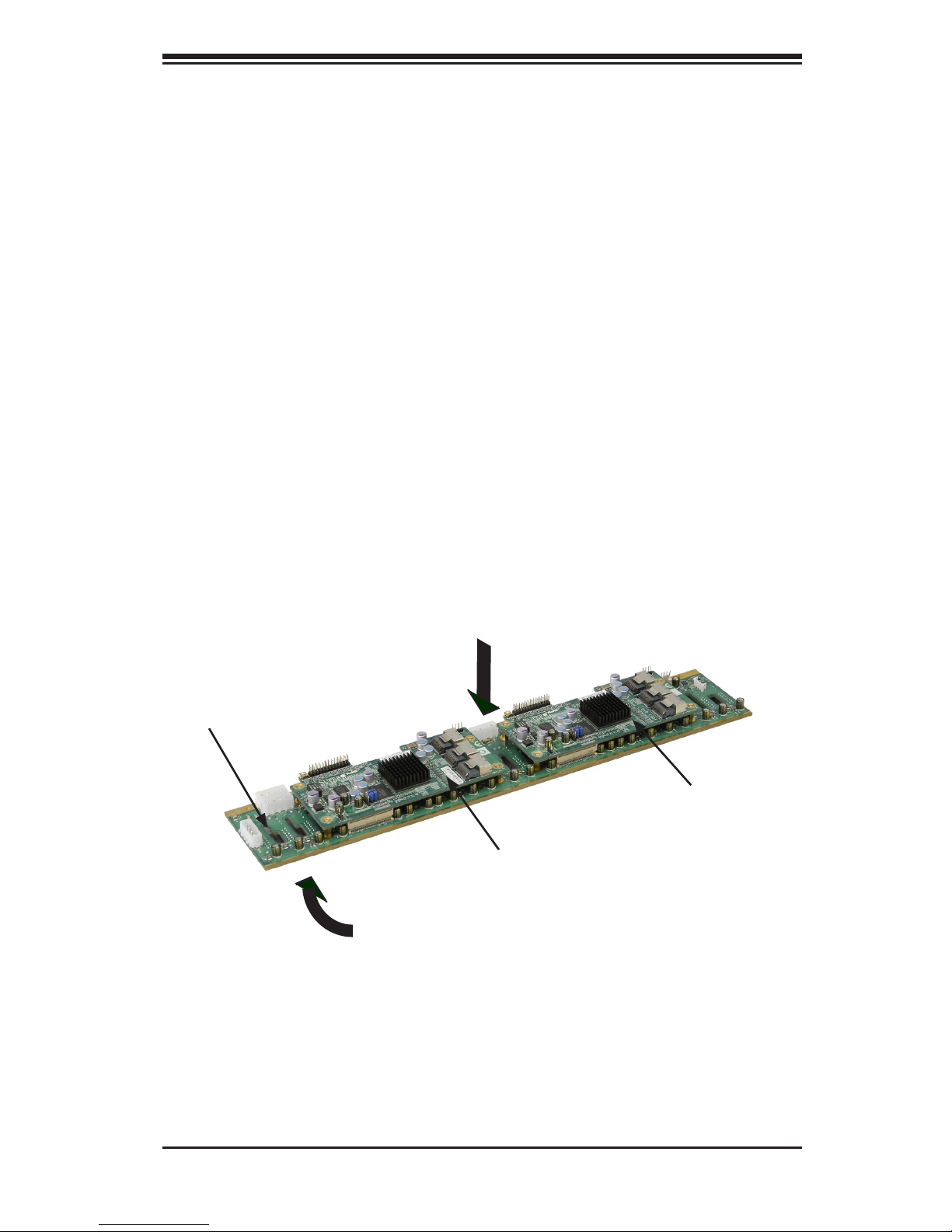
Overview of the BPN-SAS2-216EL1/EL2 Backplanes
The BPN-SAS2-216EL1/EL2 model backplanes consists of a BPN-SAS2-216EB
backplane (X) with one or two BPN-SAS2-216EL daughter cards (Y and Z) mounted
on the rear of the backplane.
The BPN-SAS2-216EL1 model consists of the BPN-SAS2-216EB backplane (X)
and one BPN-SAS2-216EL primary daughter card (Y), mounted on the right-hand
side of the backplane.
The BPN-SAS2-216EL2 model consists of the BPN-SAS2-216EB backplane (X)
with a BPN-SAS2-216EL primary daughter card mounted on the right (Y) and a
BPN-SAS2-216EL secondary daughter card mounted on the left (Z).
Components on the front side of the BPN-SAS2-216EB backplane include twenty-
four SAS connectors and their respecitve activity and failure LEDs. Components
on the rear side of the backplane include jumpers and power and fan connectors.
Thedaughtercard'scomponentsincludeSASports,ashandexpanderchips,and
mode select jumpers.
BPN-SAS2-216EL Secondary
Daughter Card (Z)
BPN-SAS2-216EB
Backplane (X)
BPN-SAS2-216EL Primary
Daughter Card (Y)
Rear Side of the Backplane
Front Side of the Backplane
Page 8

viii
BPN-SAS2-216EL1/EL2 Backplane User's Guide
Notes
Page 9

1-1
Chapter 1 Safety Guidelines
Chapter 1
Safety Guidelines
To avoid personal injury and property damage, carefully follow all the safety steps
listed below when accessing your system or handling the components.
1-1 ESD Safety Guidelines
Electrostatic Discharge (ESD) can damage electronic com ponents. To prevent damage
to your system, it is important to handle the backplane very carefully. The following
measures are generally sufcient to protect your equipment from ESD.
•Use a grounded wrist strap designed to prevent static discharge.
•Touch a grounded metal object before removing a component from the antistatic
bag.
•Handle the backplane and daughter cards by their edges only; do not touch the
components, peripheral chips, memory modules or gold contacts.
•When handling chips or modules, avoid touching their pins.
•Put the backplane and peripherals back into their antistatic bags when not in
use.
1-2 General Safety Guidelines
•Always disconnect power cables before installing or removing any components
from the computer, including the backplane.
•Disconnect the power cable before installing or removing any cables from the
backplane.
•Make sure that the backplane is securely and properly installed on the mother-
board to prevent damage to the system due to power shortage.
Page 10

1-2
BPN-SAS2-216EL1/EL2 Backplane User's Guide
1-3 An Important Note to Users
All images and layouts shown in this user's guide are based upon the latest PCB
Revision available at the time of publishing. The card you have received may or
may not look exactly the same as the graphics shown in this manual.
1-4 Introduction to the BPN-SAS2-216EL1/EL2
Backplane
The BPN-SAS2-216EL1/EL2 model backplane has been designed to utilize the
most up-to-date technology available, providing your system with reliable, high-
quality performance.
ThismanualreectstheBPN-SAS2-216ELRevision1.02backplane,themostcur-
rent release available at the time of publication.
This manual also describes the BPN-SAS2-216EL daughter card, Revision 1.02,
the most current release available at the time of publication. Always refer to the
Supermicro Web site at www.supermicro.com for the latest updates, compatible
partsandsupportedcongurations.
Page 11
2-1
Chapter 2 Connectors, Daughter Cards, Jumpers and LEDs
Chapter 2
Connectors, Daughter Cards, Jumpers and LEDs
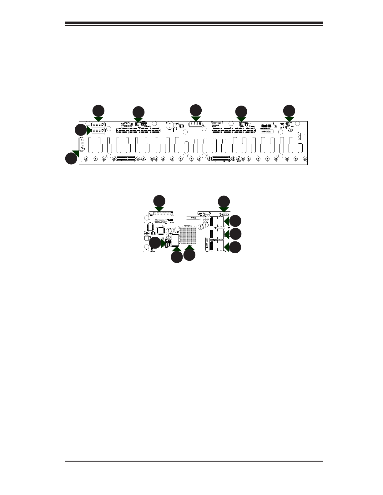
2-1 Connectors and Daughter Cards
Connectors
1. Flash Chip
2. Expander Chip
3. SAS Port: PRI_J1
4. SAS Port: PRI_J2
5. SAS Port: PRI_J3
Figure 2-1: Connectors and Daughter Cards on the BPN-SAS2-216EL
MH4
MH3
MH2
MH1
R159
R157
R158
R161
BCA534
BCA236
BCA234
1
MDIOINTERFACE
U320
ACT0
A
C
L37
18
U16
U326
16
17
32
33
48
49
64
L396
1 4
SMART_UART
14
EXPDBG1
Y9
Q3
PRI_MODE2
1
3
PRI_MODE1
1
3
Q1
PRI_J3
PRI_J2
PRI_J1
P_ICE_RTCK
P_ICE_TCK
P_ICE_TDO
2
1
J2
+
EC6
+
C2926
+
+
EC5
+
EC2
+
EC1
+
EC3
+
C862
+
C861
+
C860
+
+
C858
+
5
Y
E
20
R
K
10 15AE25 28
AH
WWN
BAR CODE
A
A
DESIGNED IN USA
Rev:1.02
BPN-SAS2-216EL
J25
2
64
63
J24
2
64
63
U2
Q5
1
BUZZER_ENB1
1
REMOTE_FAN_FAIL2
1
REMOTE_FAN_FAIL1
OVERHEATFAIL1
A
C
FANFAIL1
A
C
5V_LED1
A
C
12V_LED1
A
C
F2
F1
+
EC25
+
EC23
+
EC22
+
EC19
+
EC17
+
EC9
+
EC8
+
EC7
+
EC6
+
EC5
+
EC4
+
EC3
+
EC24
+
EC21
+
EC20
+
EC2
+
EC18
+
EC16
+
EC15
+
EC14
+
EC13
+
EC12
+
EC11
+
EC10
+
EC1
P1
B1
A1
A15
B15
A29
B29
A43
A56
B56B43
P2
B1
A1
A15
B15
A29
B29
A43 A56
B56B43
U3
F7 F4
F11 F10
4
1
FAN1
41
FAN2
4
1
FAN3
PRI_I2C
BUZZER1
+
R14
R16
R17
R19
BPN-SAS2-216EB
REV: 1.02
DESIGNED IN USA
BAR CODE
+5V +12V
GND GND
PWR1
+5V
+12VGND GND
PWR2
+5V +12VGND GND
PWR3
+5V
+12V
GND GND
PWR4
7
1
1
Rear of BPN-SAS2-261EB Backplane
Front of BPN-SAS2-2l6EL Daughter Card(s)
2
3
4
5
6
1
9
7
7
8
8
8
1
10
8
6. EPP Connectors: J2
7. Fan Connectors: Fan1, Fan2, and
Fan3
8. Power Connectors: PWR1 - PWR4
9. Debug Connector: EXPDBG1
10. UART Connector: SMART_UART
Page 12

2-2
BPN-SAS2-216EL1/EL2 Backplane User's Guide
2-2 FrontConnectorandPinDenitions
Backplane
Main Power
4-Pin Connector
Pin#Denition
1 +12V
2 and 3
Ground
4
+5V
8. Backplane Main Power Connectors
The 4-pin connectors are designated
PWR1, PWR2, PWR3 and PWR4. They
provide power to the backplane. See the
tableontherightforpindenitions.
7. Fan Connectors
The 4-pin connectors, designated FAN1,
FAN2, and FAN3, provide power to the fans.
Seethetableontherightforpindenitions.
Fan Connectors
Pin#Denition
1 Ground
2 +12V
3 Tachometer
4 NC
2. Expander Chips
This expander chip allows the backplane
to support dual ports, cascading, and
failover.
1. Flash Chips
The ash chip enhances the backplane
memory.
3. - 5. SAS Ports
The primary and secondary sets of SAS
ports provide expander features including
cascading and failover. From right to left
the ports are Primary 1,2,3 and Second-
ary 1,2,3.
6. EPP Ports
The EPP ports are used for manufacturer
diagnostic purposes only.
9. Debug Connector
The debug connector is designated EX-
PDBG1 and is used for manufacturer's
diagnostic purposes only.
10. UART Connector
The UART connector is designated SMART_
UART and is used for manufacturer's diag-
nostic purposes only.
Page 13

2-3
Chapter 2 Connectors, Daughter Cards, Jumpers and LEDs
MH4
MH3
MH2
MH1
R159
R157
R158
R161
BCA534
BCA236
BCA234
1
MDIOINTERFACE
U320
ACT0
A
C
L37
18
U16
U326
16
17
32
33
48
49
64
L396
1 4
SMART_UART
14
EXPDBG1
Y9
Q3
PRI_MODE2
1
3
PRI_MODE1
1
3
Q1
PRI_J3
PRI_J2
PRI_J1
P_ICE_RTCK
P_ICE_TCK
P_ICE_TDO
2
1
J2
+
EC6
+
C2926
+
+
EC5
+
EC2
+
EC1
+
EC3
+
C862
+
C861
+
C860
+
+
C858
+
5
Y
E
20
R
K
10 15AE25 28
AH
WWN
BAR CODE
A
A
DESIGNED IN USA
Rev:1.02
BPN-SAS2-216EL
MH2
R159
R157
R158
R161
BCA236
BCA234
U320
ACT0
A
C
L37
U326
49
64
L396
1 4
SMART_UART
14
EXPDBG1
Y9
PRI_MODE2
1
3
PRI_MODE1
1
3
PRI_J3
PRI_J2
P_ICE_RTCK
P_ICE_TCK
P_ICE_TDO
2
1
J2
+
C2926
+
EC2
+
EC1
+
C862
+
C861
+
C860
+
C858
+
5
Y
E
20
R
K
10 15
AE
25 28
AH
WWN
BAR CODE
A
A
DESIGNED IN USA
Rev:1.02
2-3 Jumper Locations and Settings
Explanation of Jumpers
To modify the operation of the backplane,
jumpers can be used to choose between
optional settings. Jumpers create shorts
between two pins to change the function
of the connector. Pin 1 is identied with
a square solder pad on the printed circuit
board. Note: On two pin jumpers, "Closed"
means the jumper is on and "Open" means
the jumper is off the pins.
Connector
Pins
Jumper
Setting
3 2 1
3 2 1
J25
2
64
63
J24
2
64
63
U2
Q5
1
BUZZER_ENB1
1
REMOTE_FAN_FAIL2
1
REMOTE_FAN_FAIL1
OVERHEATFAIL1
A
C
FANFAIL1
A
C
5V_LED1
A
C
12V_LED1
A
C
F2
F1
+
EC25
+
EC23
+
EC22
+
EC19
+
EC17
+
EC9
+
EC8
+
EC7
+
EC6
+
EC5
+
EC4
+
EC3
+
EC24
+
EC21
+
EC20
+
EC2
+
EC18
+
EC16
+
EC15
+
EC14
+
EC13
+
EC12
+
EC11
+
EC10
+
EC1
P1
B1
A1
A15
B15
A29
B29
A43
A56
B56B43
P2
B1
A1
A15
B15
A29
B29
A43 A56
B56B43
U3
F7 F4
F11 F10
4
1
FAN1
41
FAN2
4
1
FAN3
PRI_I2C
BUZZER1
+
R14
R16
R17
R19
BPN-SAS2-216EB
REV: 1.02
DESIGNED IN USA
BAR CODE
+5V +12V
GND GND
PWR1
+5V
+12VGND GND
PWR2
+5V +12VGND GND
PWR3
+5V
+12V
GND GND
PWR4
U2
1
BUZZER_ENB1
1
REMOTE_FAN_FAIL2
1
REMOTE_FAN_FAIL1
OVERHEATFAIL1
A
C
FANFAIL1
A
C
P1
B1
A1
A15
B15
A29
B29
A29
B29
A43 A56
B56B43
FAN2
4
1
FAN3
BUZZER1
+
BPN-SAS2-216EB
REV: 1.02
+5V
+12V
GND GND
PWR4
REMOTE_FAN_FAIL1
REMOTE_FAN_FAIL2
BUZZER_ENB1
Figure2-2:JumperLocationsandPinDemitions
PRI_MODE1
PRI_
MODE2
Rear of BPN-SAS2-261EB Backplane
Front of BPN-SAS2-2l6EL Daughter Card
Page 14

2-4
BPN-SAS2-216EL1/EL2 Backplane User's Guide
General Jumper Settings
Jumper Jumper Settings Note
PRI_MODE1 Pins 2-3 Factory setting, do not change
PRI_MODE2 Pins 2-3 Factory setting do not change
REMOTE_FAN_FAIL1
Open: Enable (Default)
Closed: Disable
Enables/disables the fan speed
reporting.
REMOTE_FAN_FAIL2
Open: Enable
Closed:Disable (Default)
Enables/disables the FANFAIL1 LED
BUZZER_ENB1
Open: Disable (Default)
Closed: Enable
Buzzer enable*
*The buzzer sound indicates that a condition requiring immediate attention has
occurred.
The buzzer alarm is triggered by any of the following conditions:
1. Hard drive failure
2. Fan failure
3. System temperature over 45º Celsius.
Page 15

2-5
Chapter 2 Connectors, Daughter Cards, Jumpers and LEDs
Rear LEDs
LED Fail State Specication
12V_LED1 Off
Green LED indicates backplane 12V power. Light is on
during normal operation.
5V_LED1 Off
Blue LED indicates backplane 5V power. Light is on during
normal operation.
FANFAIL1 On
Red LED indicates a fan failure. Light is off during normal
operation
OVERHEATFAIL1 On
Red LED indicates an overheat condition. Light is off during normal operation
J25
2
64
63
J24
2
64
63
U2
Q5
1
BUZZER_ENB1
1
REMOTE_FAN_FAIL2
1
REMOTE_FAN_FAIL1
OVERHEATFAIL1
A
C
FANFAIL1
A
C
5V_LED1
A
C
12V_LED1
A
C
F2
F1
+
EC25
+
EC23
+
EC22
+
EC19
+
EC17
+
EC9
+
EC8
+
EC7
+
EC6
+
EC5
+
EC4
+
EC3
+
EC24
+
EC21
+
EC20
+
EC2
+
EC18
+
EC16
+
EC15
+
EC14
+
EC13
+
EC12
+
EC11
+
EC10
+
EC1
P1
B1
A1
A15
B15
A29
B29
A43
A56
B56B43
P2
B1
A1
A15
B15
A29
B29
A43 A56
B56B43
U3
F7 F4
F11 F10
4
1
FAN1
41
FAN2
4
1
FAN3
PRI_I2C
BUZZER1
+
R14
R16
R17
R19
BPN-SAS2-216EB
REV: 1.02
DESIGNED IN USA
BAR CODE
+5V +12V
GND GND
PWR1
+5V
+12VGND GND
PWR2
+5V +12VGND GND
PWR3
+5V
+12V
GND GND
PWR4
5V_LED1
OVERHEATFAIL1
FANFAIL1
12V_LED1
Figure 2-3: Rear LEDs
Page 16

2-6
BPN-SAS2-216EL1/EL2 Backplane User's Guide
2-4 Front Connectors and LED Indicators
Front SAS/SATA Connectors
Front
Connector
SAS Drive
Number
Front
Connector
SAS Drive
Number
SAS #J0 SAS/SATA HDD #1 SAS #J12 SAS/SATA HDD #13
SAS #J1 SAS/SATA HDD #2 SAS #J13 SAS/SATA HDD #14
SAS #J2 SAS/SATA HDD #3 SAS #J14 SAS/SATA HDD #15
SAS #J3
SAS/SATA HDD #4
SAS #J15
SAS/SATA HDD #16
SAS #J4
SAS/SATA HDD #5
SAS #J16
SAS/SATA HDD #17
SAS #J5 SAS/SATA HDD #6 SAS #J17 SAS/SATA HDD #18
SAS #J6
SAS/SATA HDD #7
SAS #J18
SAS/SATA HDD #19
SAS #J7 SAS/SATA HDD #8 SAS #J19 SAS/SATA HDD #20
SAS #J8 SAS/SATA HDD #9 SAS #J20 SAS/SATA HDD #21
SAS #J9 SAS/SATA HDD #10 SAS #J21 SAS/SATA HDD #22
SAS #J10
SAS/SATA HDD #11
SAS #J22
SAS/SATA HDD #23
SAS #J11 SAS/SATA HDD #12 SAS #J23 SAS/SATA HDD #24
U1
FAIL9
A
C
FAIL8
A
C
FAIL7
A
C
FAIL6
A
C
FAIL5
A
C
FAIL4
A C
FAIL3
A
C
FAIL23
A
C
FAIL22
A
C
FAIL21
A C
FAIL20
A
C
FAIL2
A
C
FAIL19
A
C
FAIL18
A
C
FAIL17
A C
FAIL16
A C
FAIL15
A C
FAIL14
A C
FAIL13
A
C
FAIL12
C
FAIL11
A
C
FAIL10
A
C
FAIL1
A
C
ACT9
A
C
ACT8
A
C
ACT7
A C
ACT6
A
C
ACT5
A
C
ACT4
A C
ACT3
A
C
ACT23
A C
ACT22
A
C
ACT21
A
C
ACT20
A C
ACT2
A
C
ACT19
A
C
ACT18
A
C
ACT17
A
C
ACT16
A
C
ACT15
A C
ACT14
A C
ACT13
A
C
ACT12
A
C
ACT11
A C
ACT10
A
C
ACT1
A
C
ACT0
A
C
FAIL0
A
C
C65
J7
22
21
33 27
8
9
J6
22
21
33
27
8
9
J5
22
21
33 27
8
9
J0
22
21
33
8 7
9
J1
22
21
33
27
8
9
J10
22
21
33 27
8
9
J11
22
21
33
27
8
9
J12
22
21
33
27
8
9
J13
22
21
33 27
8
9
J14
22
21
33
27
8
9
J15
22
21
33
27
8
7
9
J16
22
21
33
879
J17
22
21
33
8 7
9
J18
22
21
8 7
9
J19
22
21
33
8 7
9
J2
22
21
33
27
8
9
J20
22
21
33
8
7
9
J21
22
21
33
8
7
9
J9
22
21
33
27
8
9
J8
22
21
33
27
8
9
J4
22
21
33
27
8
9
J3
22
21
33
27
8
9
J22
22
21
33
8
7
9
J23
22
21
33
27
8
7
9
R38
R40
R8
MH9
MH7
MH5
MH4
MH2
MH12 MH11 MH10
MH1
MH3 MH6
MH8
SAS #J0
SAS #J1
SAS #J2
SAS #J3
SAS #J4
SAS #J5
SAS #J6
SAS #J7
SAS #J8
SAS #J9
SAS #J10
SAS #J11
SAS #J12
SAS #J13
SAS #J14
SAS #J15
SAS #J16
SAS #J17
SAS #J18
SAS #J19
SAS #J20
SAS #J21
SAS #J22
SAS #J23
ACT #23, FAIL#23
ACT #22, FAIL#22
ACT #21, FAIL#21
ACT #20, FAIL#20
ACT #19, FAIL#19
ACT #18, FAIL#18
ACT #17, FAIL#17
ACT #16, FAIL#16
ACT #15, FAIL#15
ACT #14, FAIL#14
ACT #13, FAIL#13
ACT #12, FAIL#12
ACT #11, FAIL#11
ACT #10, FAIL#10
ACT #9, FAIL#9
ACT #8, FAIL#8
ACT #7, FAIL#7
ACT #6, FAIL#6
ACT #5, FAIL#5
ACT #4, FAIL#4
ACT #3, FAIL#3
ACT #2, FAIL#2
ACT #1, FAIL#1
ACT #0, FAIL#0
Figure 2-4: Front Connectors and LEDs
Page 17

2-7
Chapter 2 Connectors, Daughter Cards, Jumpers and LEDs
Front LED Indicators
Front LED Hard Drive Activity Failure LED
SAS #J0 ACT #0 FAIL #0
SAS #J1 ACT #1 FAIL #1
SAS #J2 ACT #2 FAIL #2
SAS #J3 ACT #3 FAIL #3
SAS #J4 ACT #4 FAIL #4
SAS #J5 ACT #5 FAIL #5
SAS #J6 ACT #6 FAIL #6
SAS #J7 ACT #7 FAIL #7
SAS #J8 ACT #8 FAIL #8
SAS #J9 ACT #9 FAIL #9
SAS #J10 ACT #10 FAIL #10
SAS #J11 ACT #11 FAIL #11
SAS #J12 ACT #12 FAIL #12
SAS #J13 ACT #13 FAIL #13
SAS #J14 ACT #14 FAIL #14
SAS #J15 ACT #15 FAIL #15
SAS #J16 ACT #16 FAIL #16
SAS #J17 ACT #17 FAIL #17
SAS #J18 ACT #18 FAIL #18
SAS #J19 ACT #19 FAIL #19
SAS #J20 ACT #20 FAIL #20
SAS #J21 ACT #21 FAIL #21
SAS #J22 ACT #22 FAIL #22
SAS #J23 ACT #23 FAIL #23
Page 18

2-8
BPN-SAS2-216EL1/EL2 Backplane User's Guide
Notes
Page 19

3-1
Chapter 3 Dual Port and Cascading Congurations
MH4
MH3
MH2
MH1
R159
R157
R158
R161
BCA534
BCA236
BCA234
1
MDIOINTERFACE
U320
ACT0
A
C
L37
18
U16
U326
16
17
32
33
48
49
64
L396
1 4
SMART_UART
14
EXPDBG1
Y9
Q3
PRI_MODE2
1
3
PRI_MODE1
1
3
Q1
PRI_J3
PRI_J2
PRI_J1
P_ICE_RTCK
P_ICE_TCK
P_ICE_TDO
2
1
J2
+
EC6
+
C2926
+
+
EC5
+
EC2
+
EC1
+
EC3
+
C862
+
C861
+
C860
+
+
C858
+
5
Y
E
20
R
K
10 15AE25 28
AH
WWN
BAR CODE
A
A
DESIGNED IN USA
Rev:1.02
BPN-SAS2-216EL
Port B Secondary Ports Expander 2
From HBA
or higher
backplane
From HBA
or higher
backplane
From HBA
or higher
backplane
To Lower Backplane in
Cascaded System
To Lower Backplane in
Cascaded System
Port A Primary Ports Expander 1
Chapter 3
DualPortandCascadingCongurations
3-1 Single and Dual Port Expanders
Single Ports
BPN-SAS2-216EL1 model backplanes have a single-port expander on the daughter
card that accesses all of the drives and supports cascading.
Figure3-2:BPN-SAS2-216EL2DualPortConguration
J3
J2
J1
MH4
MH3
MH2
MH1
R159
R157
R158
R161
BCA534
BCA236
BCA234
1
MDIOINTERFACE
U320
ACT0
A
C
L37
18
U16
U326
16
17
32
33
48
49
64
L396
1 4
SMART_UART
14
EXPDBG1
Y9
Q3
PRI_MODE2
1
3
PRI_MODE1
1
3
Q1
PRI_J3
PRI_J2
PRI_J1
P_ICE_RTCK
P_ICE_TCK
P_ICE_TDO
2
1
J2
+
EC6
+
C2926
+
+
EC5
+
EC2
+
EC1
+
EC3
+
C862
+
C861
+
C860
+
+
C858
+
5
Y
E
20
R
K
10 15AE25 28
AH
WWN
BAR CODE
A
A
DESIGNED IN USA
Rev:1.02
BPN-SAS2-216EL
J3
J2
J1
To Lower Backplane in
Cascaded System
Dual Ports
BPN-SAS2-216EL2 model backplanes have dual-port expanders on the daughter
cards that access all of the hard drives. These dual-port expanders support cascad-
ing, failover, and recovery.
J3
J2
J1
Port A Primary Ports Expander 1
Figure3-1:BPN-SAS2-216EL1SinglePortConguration
Page 20

3-2
BPN-SAS2-216EL1/EL2 Backplane User's Guide
Single Host Bus Adapter
In a single host bus conguration, the
backplane connects to one Host Bus
Adapter (HBA).
The BPN-SAS2-216EL2 model backplane has two expanders which enable effec-
tive failover and recovery.
3-2 Failover
Port A
Expander 1
Port B
Expander 2
Single Host Bus Adapter
Failover
If the expander or data path in Port A
fails, the system automatically switches
to Port B.
Figure 3-4: Single HBA Failover
MH4
MH3
MH2
MH1
R159
R157
R158
R161
BCA534
BCA236
BCA234
1
MDIOINTERFACE
U320
ACT0
A
C
L37
18
U16
U326
16
17
32
33
48
49
64
L396
1 4
SMART_UART
14
EXPDBG1
Y9
Q3
PRI_MODE2
1
3
PRI_MODE1
1
3
Q1
PRI_J3
PRI_J2
PRI_J1
P_ICE_RTCK
P_ICE_TCK
P_ICE_TDO
2
1
J2
+
EC6
+
C2926
+
+
EC5
+
EC2
+
EC1
+
EC3
+
C862
+
C861
+
C860
+
+
C858
+
5
Y
E
20
R
K
10 15AE25 28
AH
WWN
BAR CODE
A
A
DESIGNED IN USA
Rev:1.02
BPN-SAS2-216EL
SAS HBA
Port A
Expander 1
Port B
Expander 2
Figure 3-3: Single HBA
MH4
MH3
MH2
MH1
R159
R157
R158
R161
BCA534
BCA236
BCA234
1
MDIOINTERFACE
U320
ACT0
A
C
L37
18
U16
U326
16
17
32
33
48
49
64
L396
1 4
SMART_UART
14
EXPDBG1
Y9
Q3
PRI_MODE2
1
3
PRI_MODE1
1
3
Q1
PRI_J3
PRI_J2
PRI_J1
P_ICE_RTCK
P_ICE_TCK
P_ICE_TDO
2
1
J2
+
EC6
+
C2926
+
+
EC5
+
EC2
+
EC1
+
EC3
+
C862
+
C861
+
C860
+
+
C858
+
5
Y
E
20
R
K
10 15AE25 28
AH
WWN
BAR CODE
A
A
DESIGNED IN USA
Rev:1.02
BPN-SAS2-216EL
SAS HBA
Page 21

3-3
Chapter 3 Dual Port and Cascading Congurations
Port A
Expander 1
Port B
Expander 2
Dual Host Bus Adapter
In a dual host bus conguration, the
backplane connects to two HBA's.
Figure 3-5: Dual HBA
Dual Host Bus Adapter
Failover
If the expander or data path in Port A
fails, the system automatically switches
to Port B. This maintains a full connec-
tion to all drives.
Figure 3-6: Dual HBA Failover
MH4
MH3
MH2
MH1
R159
R157
R158
R161
BCA534
BCA236
BCA234
1
MDIOINTERFACE
U320
ACT0
A
C
L37
18
U16
U326
16
17
32
33
48
49
64
L396
1 4
SMART_UART
14
EXPDBG1
Y9
Q3
PRI_MODE2
1
3
PRI_MODE1
1
3
Q1
PRI_J3
PRI_J2
PRI_J1
P_ICE_RTCK
P_ICE_TCK
P_ICE_TDO
2
1
J2
+
EC6
+
C2926
+
+
EC5
+
EC2
+
EC1
+
EC3
+
C862
+
C861
+
C860
+
+
C858
+
5
Y
E
20
R
K
10 15AE25 28
AH
WWN
BAR CODE
A
A
DESIGNED IN USA
Rev:1.02
BPN-SAS2-216EL
SAS HBA
SAS HBA
MH4
MH3
MH2
MH1
R159
R157
R158
R161
BCA534
BCA236
BCA234
1
MDIOINTERFACE
U320
ACT0
A
C
L37
18
U16
U326
16
17
32
33
48
49
64
L396
1 4
SMART_UART
14
EXPDBG1
Y9
Q3
PRI_MODE2
1
3
PRI_MODE1
1
3
Q1
PRI_J3
PRI_J2
PRI_J1
P_ICE_RTCK
P_ICE_TCK
P_ICE_TDO
2
1
J2
+
EC6
+
C2926
+
+
EC5
+
EC2
+
EC1
+
EC3
+
C862
+
C861
+
C860
+
+
C858
+
5
Y
E
20
R
K
10 15AE25 28
AH
WWN
BAR CODE
A
A
DESIGNED IN USA
Rev:1.02
BPN-SAS2-216EL
MH4
MH3
MH2
MH1
R159
R157
R158
R161
BCA534
BCA236
BCA234
1
MDIOINTERFACE
U320
ACT0
A
C
L37
18
U16
U326
16
17
32
33
48
49
64
L396
1 4
SMART_UART
14
EXPDBG1
Y9
Q3
PRI_MODE2
1
3
PRI_MODE1
1
3
Q1
PRI_J3
PRI_J2
PRI_J1
P_ICE_RTCK
P_ICE_TCK
P_ICE_TDO
2
1
J2
+
EC6
+
C2926
+
+
EC5
+
EC2
+
EC1
+
EC3
+
C862
+
C861
+
C860
+
+
C858
+
5
Y
E
20
R
K
10 15AE25 28
AH
WWN
BAR CODE
1.02
REV:
MACH FINISH
30
ANGLE
SPECIFIED DIMENSIONS
UNLESS OTHERWISE
XXX.03
.1
TOLERANCES
DECIMAL
ARE IN INCHES
Minh Hong/Max
DESIGNER:
DATE: 12/03/2009
DESIGNED BY SUPERMICRO U.S.A.
www.supermicro.com
SILKSCREEN
PRIMARY-SIDE
S
UPER
R
S
UPERSUPERSUPERSUPERSUPERSUPERSUPERSUPERSUPERSUPERSUPERSUPERSUPERSUPERSUPERSUPERSUPER
RRRRRRRRRR
A
A
DESIGNED IN USA
Rev:1.02
BPN-SAS2-216EL
SAS HBA
SAS HBA
Port A
Expander 1
Port B
Expander 2
IMPORTANT: For RAID controllers, redundancy is achieved through port
failover. For multiple HBAs MPIO software is required to achieve failover
protection.
3-3 Failover with RAID Cards and Multiple HBAs
TheSAS-216ELbackplanemaybeconguredforfailoverwithmultipleHBAsusing
either RAID controllers or HBAs to acheive failover protection.
RAID Controllers: If RAID controllers are used, then the failover is accomplished
through port failover on the same RAID card.
HBAs: If multiple HBAs are used to achieve failover protection and load balancing,
LinuxMPIO software must be installed and correctly congured to perform
the load balancing and failover tasks.
Page 22

3-4
BPN-SAS2-216EL1/EL2 Backplane User's Guide
3-4 Chassis Power Card and Support Cables
Power Card
Part Number Part Type Where Used
CSE-PTJBOD-CB2 Power Card
Allows the chassis to be used as
a JBOD (Just a Bunch of Drives)
system.
Chassis Power Card
Inacascadedconguration,therstchassisincludesamotherboardandatleast
one host bus adapter (HBA). Other servers in this enclosed system must be
equipped with a power card. This section describes the supported power card for
the BPN-SAS2-216EL series backplane.
For more information, see the Supermicro web site at http://www.supermicro.com.
+
C38
Q1
BUZZER1
J1
1 12
13 24
F5
F9
F8
F7
F4
F3
F2
F1
C1
C3
U3
U1
+
EC3
+
EC2
+
EC1
D1
A
C
MH4
MH3
MH2
MH1
JF1
1
2
19
20
U7
J17
1
5
4
1
FAN8/X
4
1
FAN7/X
4
1
FAN6/X
4
1
FAN5/X
4
1
FAN1
4
1
FAN2
4
1
FAN3
4
1
FAN4
I2C
3 2 1
U2
U4
U8
J13
1
BAR CODE
JP7
X
HDD PWR
NMI
LEDLED
NIC1
PWR
OH
/FF
NIC2
PWR
FAIL
RST
ON
REV 1.01
CSE-PTJBOD-CB2
Figure 3-7: Chassis Power Card (Sold Separately)
Page 23

3-5
Chapter 3 Dual Port and Cascading Congurations
Figure 3-9: Dual Internal Host Bus Adapter
Supported Internal HBA Cables
Use the following cables to create connections between the internal HBA and BPN-
SAS2-216EL model backplane. The cables required depend upon the HBA connector.
Cable Name: iPass to 4-LANE
Part #: CBL-0117L
Length: 46 cm (18 inches)
Description: This cable has one SFF-8484 (32-pin) connector at one end and one
iPass (SFF-8087/Mini-SAS) connector (36-pin) at the other. This cable connects from
the HBA to the BPN-SAS2-216EL backplane
Connecting an Internal HBA to the Backplane
The following section lists the most common cables used to connect the HBA to
the backplane.
Figure 3-8: Single Internal Host Bus Adapter
HBA HBA
MH4
MH3
MH2
MH1
R159
R157
R158
R161
BCA534
BCA236
BCA234
1
MDIOINTERFACE
U320
ACT0
A
C
L37
18
U16
U326
16
17
32
33
48
49
64
L396
1 4
SMART_UART
14
EXPDBG1
Y9
Q3
PRI_MODE2
1
3
PRI_MODE1
1
3
Q1
PRI_J3
PRI_J2
PRI_J1
P_ICE_RTCK
P_ICE_TCK
P_ICE_TDO
2
1
J2
+
EC6
+
C2926
+
+
EC5
+
EC2
+
EC1
+
EC3
+
C862
+
C861
+
C860
+
+
C858
+
5
Y
E
20
R
K
10 15AE25 28
AH
WWN
BAR CODE
A
A
DESIGNED IN USA
Rev:1.02
BPN-SAS2-216EL
HBA
MH4
MH3
MH2
MH1
R159
R157
R158
R161
BCA534
BCA236
BCA234
1
MDIOINTERFACE
U320
ACT0
A
C
L37
18
U16
U326
16
17
32
33
48
49
64
L396
1 4
SMART_UART
14
EXPDBG1
Y9
Q3
PRI_MODE2
1
3
PRI_MODE1
1
3
Q1
PRI_J3
PRI_J2
PRI_J1
P_ICE_RTCK
P_ICE_TCK
P_ICE_TDO
2
1
J2
+
EC6
+
C2926
+
+
EC5
+
EC2
+
EC1
+
EC3
+
C862
+
C861
+
C860
+
+
C858
+
5
Y
E
20
R
K
10 15AE25 28
AH
WWN
BAR CODE
A
A
DESIGNED IN USA
Rev:1.02
BPN-SAS2-216EL
IMPORTANT: See Section 3-3 of this manual, Failover with RAID Cards and Multiple
HBAsforimportantinformationonsupportedcongurations.
Page 24

3-6
BPN-SAS2-216EL1/EL2 Backplane User's Guide
Cable Name: iPass (Mini-SAS) to iPass (Mini-SAS)
Part #: CBL-0108L-02 Length: 39 cm (15 inches)
Part #: CBL-0109L-02 Length: 22 cm (9 inches)
Part #: CBL-0110L-02 Length: 18 cm (7 inches)
Description: This cable has an iPass (SFF-8087/Mini-SAS) connector (36-pin) at each
end. It connects from the HBA to the BPN-SAS2-216EL model backplane.
Page 25

3-7
Chapter 3 Dual Port and Cascading Congurations
MH4
MH3
MH2
MH1
R159
R157
R158
R161
BCA534
BCA236
BCA234
1
MDIOINTERFACE
U320
ACT0
A
C
L37
18
U16
U326
16
17
32
33
48
49
64
L396
1 4
SMART_UART
14
EXPDBG1
Y9
Q3
PRI_MODE2
1
3
PRI_MODE1
1
3
Q1
PRI_J3
PRI_J2
PRI_J1
P_ICE_RTCK
P_ICE_TCK
P_ICE_TDO
2
1
J2
+
EC6
+
C2926
+
+
EC5
+
EC2
+
EC1
+
EC3
+
C862
+
C861
+
C860
+
+
C858
+
5
Y
E
20
R
K
10 15AE25 28
AH
WWN
BAR CODE
A
A
DESIGNED IN USA
Rev:1.02
BPN-SAS2-216EL
Connecting an External HBA to the Backplane
Thisbackplanesupportsexternalhostbusadapters.Inthisconguration,theHBA
and the backplane are in different physical chassis. This allows a JBOD (Just a
BunchOfDrives)congurationfromanexistingsystem.
HBA
Power Card
HBA
Dual External Host Bus Adapter
CBL-0166L
External HBA Cables
HBA
Power Card
CBL-0166L
External HBA Cable
MH4
MH3
MH2
MH1
R159
R157
R158
R161
BCA534
BCA236
BCA234
1
MDIOINTERFACE
U320
ACT0
A
C
L37
18
U16
U326
16
17
32
33
48
49
64
L396
1 4
SMART_UART
14
EXPDBG1
Y9
Q3
PRI_MODE2
1
3
PRI_MODE1
1
3
Q1
PRI_J3
PRI_J2
PRI_J1
P_ICE_RTCK
P_ICE_TCK
P_ICE_TDO
2
1
J2
+
EC6
+
C2926
+
+
EC5
+
EC2
+
EC1
+
EC3
+
C862
+
C861
+
C860
+
+
C858
+
5
Y
E
20
R
K
10 15AE25 28
AH
WWN
BAR CODE
A
A
DESIGNED IN USA
Rev:1.02
BPN-SAS2-216EL
Figure 3-10: Single External Host Adapter
Figure 3-11: Dual External Host Bus Adapter
Single External Host Bus Adapter
MH4
MH3
MH2
MH1
R159
R157
R158
R161
BCA534
BCA236
BCA234
1
MDIOINTERFACE
U320
ACT0
A
C
L37
18
U16
U326
16
17
32
33
48
49
64
L396
1 4
SMART_UART
14
EXPDBG1
Y9
Q3
PRI_MODE2
1
3
PRI_MODE1
1
3
Q1
PRI_J3
PRI_J2
PRI_J1
P_ICE_RTCK
P_ICE_TCK
P_ICE_TDO
2
1
J2
+
EC6
+
C2926
+
+
EC5
+
EC2
+
EC1
+
EC3
+
C862
+
C861
+
C860
+
+
C858
+
5
Y
E
20
R
K
10 15AE25 28
AH
WWN
BAR CODE
A
A
DESIGNED IN USA
Rev:1.02
BPN-SAS2-216EL
IMPORTANT: See Section 3-3 of this manual, Failover with RAID Cards and Multiple
HBAsforimportantinformationonsupportedcongurations.
Page 26

3-8
BPN-SAS2-216EL1/EL2 Backplane User's Guide
Supported External HBA to Backplane Cable
UsethefollowingcableifyourexternalHBAhasanInniBandconnector.
Figure3-12:SASInniBandCable(CBL-0200L)
Cable Name:SASInniBandtoMini-SASX41Mcable,PBF
Part #: CBL-0200L
Length: 1 meter
Description:ThiscablehasanInniBandconnector(SFF-8470)ononeendandan
SFF-8088-1X (26-pin) connector at the other end.
Page 27

3-9
Chapter 3 Dual Port and Cascading Congurations
CBL-0167L
with Single Port Assembly
(Internal cable)
CBL-0166L
(External cable)
HBA
Port B Expander 2
Power Card
Port B Expander 2
Port A Expander 1
Connecting Multiple Backplanes in a Single Channel
Environment
This section describes the cables used when cascading from a single HBA. These
connections use CBL-0167L internal cables and CBL-0166L external cables.
Figure3-13:SingleHBAConguration
Port A Expander 1
MH4
MH3
MH2
MH1
R159
R157
R158
R161
BCA534
BCA236
BCA234
1
MDIOINTERFACE
U320
ACT0
A
C
L37
18
U16
U326
16
17
32
33
48
49
64
L396
1 4
SMART_UART
14
EXPDBG1
Y9
Q3
PRI_MODE2
1
3
PRI_MODE1
1
3
Q1
PRI_J3
PRI_J2
PRI_J1
P_ICE_RTCK
P_ICE_TCK
P_ICE_TDO
2
1
J2
+
EC6
+
C2926
+
+
EC5
+
EC2
+
EC1
+
EC3
+
C862
+
C861
+
C860
+
+
C858
+
5
Y
E
20
R
K
10 15AE25 28
AH
WWN
BAR CODE
A
A
DESIGNED IN USA
Rev:1.02
BPN-SAS2-216EL
Page 28

3-10
BPN-SAS2-216EL1/EL2 Backplane User's Guide
Cable Name: SAS EL2/EL1 Cascading Cable (External), 68 cm
Part #: CBL-0166L (SFF-8088 1x to SFF-8088 x1)
Ports: Single or Dual
Placement: External cable
Description: External cascading cable. Connects ports between servers. With most
connectors, use one cable for single port connections and two cables for dual port
connections.
Cable Name: SAS EL2/EL1 Backplane Cable (Internal) with 2-port Cascading Cable,
68 cm
Part #: CBL-0167L (SFF-8087 to SFF-8088 x1)
Ports: Single
Placement: Internal cable
Description: Internal cable. Connects the backplane to the HBA or external port.
Used in single port environments
SingleHBACongurationCables
Single Port Cable Assembly
Figure 3-14: Single Port Internal Cable (CBL-0167L)
Figure 3-15: External Cable (CBL-0166L)
Page 29

3-11
Chapter 3 Dual Port and Cascading Congurations
Cable 0166L
(External cable)
Port A Expander 1
HBA HBA
Power Card
Port A Expander 1
Port B Expander 2
Cable 0168L
with Single Port Assembly
(Internal cable)
Connecting Multiple Backplanes in a Dual Channel
Environment
This section describes the cables used when cascading from dual HBAs. These
connections use CBL-0168L internal cables and CBL-0166L external cables.
Figure3-16:DualHBAConguration
MH4
MH3
MH2
MH1
R159
R157
R158
R161
BCA534
BCA236
BCA234
1
MDIOINTERFACE
U320
ACT0
A
C
L37
18
U16
U326
16
17
32
33
48
49
64
L396
1 4
SMART_UART
14
EXPDBG1
Y9
Q3
PRI_MODE2
1
3
PRI_MODE1
1
3
Q1
PRI_J3
PRI_J2
PRI_J1
P_ICE_RTCK
P_ICE_TCK
P_ICE_TDO
2
1
J2
+
EC6
+
C2926
+
+
EC5
+
EC2
+
EC1
+
EC3
+
C862
+
C861
+
C860
+
+
C858
+
5
Y
E
20
R
K
10 15AE25 28
AH
WWN
BAR CODE
A
A
DESIGNED IN USA
Rev:1.02
BPN-SAS2-216EL
Port B Expander 2
IMPORTANT: See Section 3-3 of this manual, Failover with RAID Cards and Multiple
HBAsforimportantinformationonsupportedcongurations.
Page 30

3-12
BPN-SAS2-216EL1/EL2 Backplane User's Guide
Cable Name: SAS Dual-port Cable Assembly, 68/76 cm
Part #: CBL-0168L
Placement: Internal cable
Ports: Dual
Description: Internal cascading cable. Connects the backplane to the host bus
adapter or external port. Used in dual port environments.
Cable Name: SAS EL2/EL1 Cascading Cable (External), 68 cm
Part #: CBL-0166L
Placement: External Cable
Ports: Single or Dual
Description: External cascading cable. Connects ports between servers. Use one
cable for single port connections and two cables for dual port connections.
DualHBACongurationCables
Dual Port Cable
Assembly
Figure 3-18: External Cable (CBL-0166L)
Figure 3-17: Dual Port Internal Cable (CBL-0168L)
Page 31

3-13
Chapter 3 Dual Port and Cascading Congurations
Cascading allows the system to access data at a faster rate by allowing several
backplanes to share resources to reduce latency time.
The rst backplane in a cascaded system requires a motherboard and an HBA.
Other servers require a power control card with no motherboard and no HBA. For
moreinformation,specicchassismanualsareavailableatwww.supermicro.com.
3-5 SupportedCascadingCongurations
Cable 0167L
(Internal cable)
Cable 0166L
(External cable)
Single Port Cable
Assembly
HBA
Port B Expander 2
Port A Expander 1
Power Card
Port B Expander 2 Port A Expander 1
Power Card
Port B Expander 2
Port A Expander 1
Figure3-19:SimpleCascadedConguration
MH4
MH3
MH2
MH1
R159
R157
R158
R161
BCA534
BCA236
BCA234
1
MDIOINTERFACE
U320
ACT0
A
C
L37
18
U16
U326
16
17
32
33
48
49
64
L396
1 4
SMART_UART
14
EXPDBG1
Y9
Q3
PRI_MODE2
1
3
PRI_MODE1
1
3
Q1
PRI_J3
PRI_J2
PRI_J1
P_ICE_RTCK
P_ICE_TCK
P_ICE_TDO
2
1
J2
+
EC6
+
C2926
+
+
EC5
+
EC2
+
EC1
+
EC3
+
C862
+
C861
+
C860
+
+
C858
+
5
Y
E
20
R
K
10 15AE25 28
AH
WWN
BAR CODE
A
A
DESIGNED IN USA
Rev:1.02
BPN-SAS2-216EL
Page 32

3-14
BPN-SAS2-216EL1/EL2 Backplane User's Guide
Server System with Single SAS HBA
Theexpandersallow horizontalbranching.This conguration alsoapplies todual
ports.
Cable 0166L
(External cable)
Single Port Cable
Assembly
HBA
Power Card
Port A Expander 1
Power Card
Port A Expander 1
Power Card
Port A Expander 1
Power Card
Power Card
Port A Expander 1
Cable 0167L
(Internal cable)
Port A Expander 1
Figure3-20:CascadedCongurationwithHorizontalBranching
MH4
MH3
MH2
MH1
R159
R157
R158
R161
BCA534
BCA236
BCA234
1
MDIOINTERFACE
U320
ACT0
A
C
L37
18
U16
U326
16
17
32
33
48
49
64
L396
1 4
SMART_UART
14
EXPDBG1
Y9
Q3
PRI_MODE2
1
3
PRI_MODE1
1
3
Q1
PRI_J3
PRI_J2
PRI_J1
P_ICE_RTCK
P_ICE_TCK
P_ICE_TDO
2
1
J2
+
EC6
+
C2926
+
+
EC5
+
EC2
+
EC1
+
EC3
+
C862
+
C861
+
C860
+
+
C858
+
5
Y
E
20
R
K
10 15AE25 28
AH
WWN
BAR CODE
A
A
DESIGNED IN USA
Rev:1.02
BPN-SAS2-216EL
MH4
MH3
MH2
MH1
R159
R157
R158
R161
BCA534
BCA236
BCA234
1
MDIOINTERFACE
U320
ACT0
A
C
L37
18
U16
U326
16
17
32
33
48
49
64
L396
1 4
SMART_UART
14
EXPDBG1
Y9
Q3
PRI_MODE2
1
3
PRI_MODE1
1
3
Q1
PRI_J3
PRI_J2
PRI_J1
P_ICE_RTCK
P_ICE_TCK
P_ICE_TDO
2
1
J2
+
EC6
+
C2926
+
+
EC5
+
EC2
+
EC1
+
EC3
+
C862
+
C861
+
C860
+
+
C858
+
5
Y
E
20
R
K
10 15AE25 28
AH
WWN
BAR CODE
SPECIFIED DIMENSIONS
UNLESS OTHERWISE
SILKSCREEN
R
RRRRRRRRRR
A
A
DESIGNED IN USA
Rev:1.02
BPN-SAS2-216EL
MH4
MH3
MH2
MH1
R159
R157
R158
R161
BCA534
BCA236
BCA234
1
MDIOINTERFACE
U320
ACT0
A
C
L37
18
U16
U326
16
17
32
33
48
49
64
L396
1 4
SMART_UART
14
EXPDBG1
Y9
Q3
PRI_MODE2
1
3
PRI_MODE1
1
3
Q1
PRI_J3
PRI_J2
PRI_J1
P_ICE_RTCK
P_ICE_TCK
P_ICE_TDO
2
1
J2
+
EC6
+
C2926
+
+
EC5
+
EC2
+
EC1
+
EC3
+
C862
+
C861
+
C860
+
+
C858
+
5
Y
E
20
R
K
10 15AE25 28
AH
WWN
BAR CODE
A
A
DESIGNED IN USA
Rev:1.02
BPN-SAS2-216EL
Port A Expander 1
Page 33

3-15
Chapter 3 Dual Port and Cascading Congurations
Cable 0166L
(External cables)
Port A Expander 1
HBA
Power Card
Port A Expander 1
Power Card
Cable 0168L
(Internal cable)
Dual Port Cable
Assembly
Figure3-21:DualSASHBAwithCascadedConguration
DualSASHBAandCascadedConguration
HBA
Port B Expander 2
Port B Expander 2
MH4
MH3
MH2
MH1
R159
R157
R158
R161
BCA534
BCA236
BCA234
1
MDIOINTERFACE
U320
ACT0
A
C
L37
18
U16
U326
16
17
32
33
48
49
64
L396
1 4
SMART_UART
14
EXPDBG1
Y9
Q3
PRI_MODE2
1
3
PRI_MODE1
1
3
Q1
PRI_J3
PRI_J2
PRI_J1
P_ICE_RTCK
P_ICE_TCK
P_ICE_TDO
2
1
J2
+
EC6
+
C2926
+
+
EC5
+
EC2
+
EC1
+
EC3
+
C862
+
C861
+
C860
+
+
C858
+
5
Y
E
20
R
K
10 15AE25 28
AH
WWN
BAR CODE
A
A
DESIGNED IN USA
Rev:1.02
BPN-SAS2-216EL
Port A Expander 1
Port B Expander 2
IMPORTANT: See Section 3-3 of this manual, Failover with RAID Cards and Multiple
HBAsforimportantinformationonsupportedcongurations.
Page 34

3-16
BPN-SAS2-216EL1/EL2 Backplane User's Guide
Cable 0166L
(External cable)
HBA
HBA
Power Card
Port B Ex. 2
Port A Ex. 1
Power Card
Port B Ex. 2
Port A Ex. 1
Power Card
Port B Ex. 2
Port A Ex. 1
Port A Ex. 1
Power Card
Port B Ex. 2
Port A Ex. 1
Power Card
Port B Ex. 2
Figure3-22:DualSASHBACascadedCongurationandBranching
DualSASHBAandCascadedCongurationwith
Branching
MH4
MH3
MH2
MH1
R159
R157
R158
R161
BCA534
BCA236
BCA234
1
MDIOINTERFACE
U320
ACT0
A
C
L37
18
U16
U326
16
17
32
33
48
49
64
L396
1 4
SMART_UART
14
EXPDBG1
Y9
Q3
PRI_MODE2
1
3
PRI_MODE1
1
3
Q1
PRI_J3
PRI_J2
PRI_J1
P_ICE_RTCK
P_ICE_TCK
P_ICE_TDO
2
1
J2
+
EC6
+
C2926
+
+
EC5
+
EC2
+
EC1
+
EC3
+
C862
+
C861
+
C860
+
+
C858
+
5
Y
E
20
R
K
10 15AE25 28
AH
WWN
BAR CODE
A
A
DESIGNED IN USA
Rev:1.02
BPN-SAS2-216EL
Port A Ex. 1
Port B Ex. 2
IMPORTANT: See Section 3-3 of this manual, Failover with RAID Cards and Multiple
HBAsforimportantinformationonsupportedcongurations.
Page 35

3-17
Chapter 3 Dual Port and Cascading Congurations
Notes
Page 36

3-18
BPN-SAS2-216EL1/EL2 Backplane User's Guide
Disclaimer (cont.)
The products sold by Supermicro are not intended for and will not be used in life support systems, medical equipment, nuclear facilities or systems, aircraft, aircraft devices,
aircraft/emergency communication devices or other critical systems whose failure to per-
formbereasonablyexpectedtoresultinsignicantinjuryorlossoflifeorcatastrophic
property damage. Accordingly, Supermicro disclaims any and all liability, and should
buyer use or sell such products for use in such ultra-hazardous applications, it does so
entirely at its own risk. Furthermore, buyer agrees to fully indemnify, defend and hold
Supermicro harmless for and against any and all claims, demands, actions, litigation,
and proceedings of any kind arising out of or related to such ultra-hazardous use or
sale.
 Loading...