

Rev. 1.0b
AOC-USAS-L8i
USER'S GUIDE
1 3
1
4
A
C
A
C
A
C
A
C
A
C
A
C
A
C
A
C
A
C
A
C
A
C
A
C
A
C
A
C
A
C
A
C
A
C
1 3
AF
AE
AD
AC
AB
AA
Y
W
V
T
R
P
N
M
L
K
J
U
H
G
F
E
D
C
B
A
2625242322212019181716151413121110987654321
1
4
A
C
A
C
A
C
A
C
A
C
A
C
A
C
A
C
A
C
A
C
A
C
A
C
A
C
A
C
A
C
A
C
A
C
PCBEDGE
A
C
A
C
PCBEDGE

ii
Add-on Card User's Guide
The information in this User’s Manual has been carefully reviewed and is believed to be accurate.
The vendor assumes no responsibility for any inaccuracies that may be contained in this document,
makes no commitment to update or to keep current the information in this manual, or to notify any
person or organization of the updates.
Please Note: For the most up-to-date version of
this manual, please see our web site at www.supermicro.com.
SUPERMICRO COMPUTER reserves the right to make changes to the product described in this
manual at any time and without notice. This product, including software, if any, and documenta
tion may not, in whole or in part, be copied, photocopied, reproduced, translated or reduced to any
medium or machine without prior written consent.
IN NO EVENT WILL SUPERMICRO COMPUTER BE LIABLE FOR DIRECT, INDIRECT, SPECIAL,
INCIDENTAL, SPECULATIVE OR CONSEQUENTIAL DAMAGES ARISING FROM THE USE
OR INABILITY TO USE THIS PRODUCT OR DOCUMENTATION, EVEN IF ADVISED OF THE
POSSIBILITY OF SUCH DAMAGES. IN PARTICULAR, THE VENDOR SHALL NOT HAVE
LIABILITY FOR ANY HARDWARE, SOFTWARE, OR DATA STORED OR USED WITH THE
PRODUCT, INCLUDING THE COSTS OF REPAIRING, REPLACING, INTEGRATING, INSTALLING
OR RECOVERING SUCH HARDWARE, SOFTWARE, OR DATA.
Any disputes arising between manufacturer and customer shall be governed by the laws of Santa
Clara County in the State of California, USA. The State of California, County of Santa Clara shall
be the exclusive venue for the resolution of any such disputes. Supermicro's total liability for all
claims will not exceed the price paid for the hardware product.
Manual Revision 1.0b
Release Date: October 17, 2007
Unless you request and receive written permission from SUPER MICRO COMPUTER, you may not
copy or otherwise reproduce/distribute any part of this document.
Information in this document is subject to change without notice. Other products and companies
referred to herein are trademarks or registered trademarks of their respective companies or mark
holders.
Copyright © 2007 by SUPER MICRO COMPUTER INC.
All rights reserved.
Printed in the United States of America

iii
Safety Information and Technical Specifications
Table of Contents
Introduction
Overview ........................................................................................................... vii
Product Features ............................................................................................... vi
i
Operating Systems Supported .......................................................................... vi
i
An Important Note to Users .............................................................................. vi
i
Contacting SuperMicro ..................................................................................... vii
i
Chapter 1 Safety Guidelines
1-1 ESD Safety Guidelines ........................................................................................ 1-1
1-
2 General Safety Guidelines ................................................................................... 1-1
1-
3 An Important Note to Users ................................................................................. 1-1
Chapter 2 LED Indicators and Connectors
2-1 Front Connectors and Jumpers ........................................................................... 2-1
Front Connectors ............................................................................................ 2-
1
2-2 Front Connector and Pin Definitions .................................................................... 2-2
2-3
Front Jumper Locations and Pin Definitions ........................................................ 2-3
LED INDICATORS .......................................................................................... 2-
4
Front Pane LED
s ............................................................................................ 2-4
RAID Minimum Drive Requirements ............................................................... 2-
5
Chapter 3 Driver Installation
3-1 Performing a Quick Configuration ........................................................................ 3-1
3-2 Configuring Arrays and Logic Drives .................................................................. 3-
2
Starting the MegaRAID BIOS CU ................................................................... 3-
2
Using Easy Configuration ............................................................................... 3-
3
Using New Configuration and View/Add Configuration .................................. 3-
4
Creating a Global Hotspare Drive ................................................................... 3-
6
Initializing Logical Drives ................................................................................. 3-
7
3-3 Setting the Hard Disk Write Cache and Read Ahead Policies ............................ 3-
9
3-4 Rebuilding a Drive ............................................................................................. 3-1
0
3-5 Hot Plug Support ................................................................................................3-1
1
3-6 Checking Data Consistency ............................................................................... 3-1
2
3-7 Viewing and Changing Device Properties ......................................................... 3-1
3
Viewing and Changing Adapter Properties ................................................... 3-1
4
Viewing and Changing Logical Drive Properties .......................................... 3-1
5
Viewing Physical Drive Properties ................................................................ 3-1
5

iv
Add-on Card User's Guide
3-8 Forcing Drives Online or Offline ........................................................................ 3-15
3-9 Configuring a Bootable Logical Drive ................................................................ 3-1
6
3-10 Deleting a Logical Drive ................................................................................... 3-1
6
3-11 Clearing a Storage Configuration ..................................................................... 3-1
6
Chapter 4 MegaRAID Storage Manager SoftwareOverview and
Installation
4-1 Overview .............................................................................................................. 4-1
Creating Storage Configurations ..................................................................... 4-
1
Monitoring Storage Devices ............................................................................ 4-
2
Maintaining Storage Configurations ................................................................ 4-
2
4-2 Hardware and Software Requirements ................................................................ 4-2
4-3 Installation ............................................................................................................ 4-3
Installing MegaRAID Storage Manager Software for Linux ............................ 4-
6
Linux Error Messages ..................................................................................... 4-
7
Chapter 5 MegaRAID Storage Manager Window and Menus
5-1 Starting MegaRAID Storage Manager Software .................................................. 5-1
5-2 MegaRAID Storage Manager Window ................................................................. 5-4
Physical/Logical View Panel ........................................................................... 5-
5
Properties/Operations/Graphical View Panel .................................................. 5-
6
Event Log Panel .............................................................................................. 5-
6
Menu Bar ......................................................................................................... 5-
7
File Menu .................................................................................................... 5-
7
Operations Menu ........................................................................................ 5-
7
Group Operations Menu ............................................................................. 5-
7
Log Menu ................................................................................................... 5-
8
Help Menu .................................................................................................. 5-
8
Chapter 6 Configuration
6-1 Creating a New Storage Configuration ................................................................ 6-1
Understanding Virtual Disk Parameters .......................................................... 6-
3
Using Auto Configuration ................................................................................ 6-
4
Using Guided Configuration ............................................................................ 6-
5
Using Manual Configuration: RAID 0 .............................................................. 6-
8
Using Manual Configuration: RAID 1 ............................................................ 6-1
0
Using Manual Configuration: RAID 10 .......................................................... 6-1
2
6-2 Adding Hotspare Disks ...................................................................................... 6-1
3
6-3 Changing Adjustable Task Rates ....................................................................... 6-14
6-4 Changing Virtual Disk Properties ....................................................................... 6-15
6-5 Deleting a Virtual Disk ....................................................................................... 6-15

v
Safety Information and Technical Specifications
6-6 Saving a Storage Configuration to Disk ............................................................ 6-16
6-7 Clearing a Storage Configuration from a Controller .......................................... 6-1
6
6-8 Adding a Saved Storage Configuration ............................................................. 6-1
7

vi
Add-on Card User's Guide
Notes

vii
Safety Information and Technical Specifications
Introduction
Overview
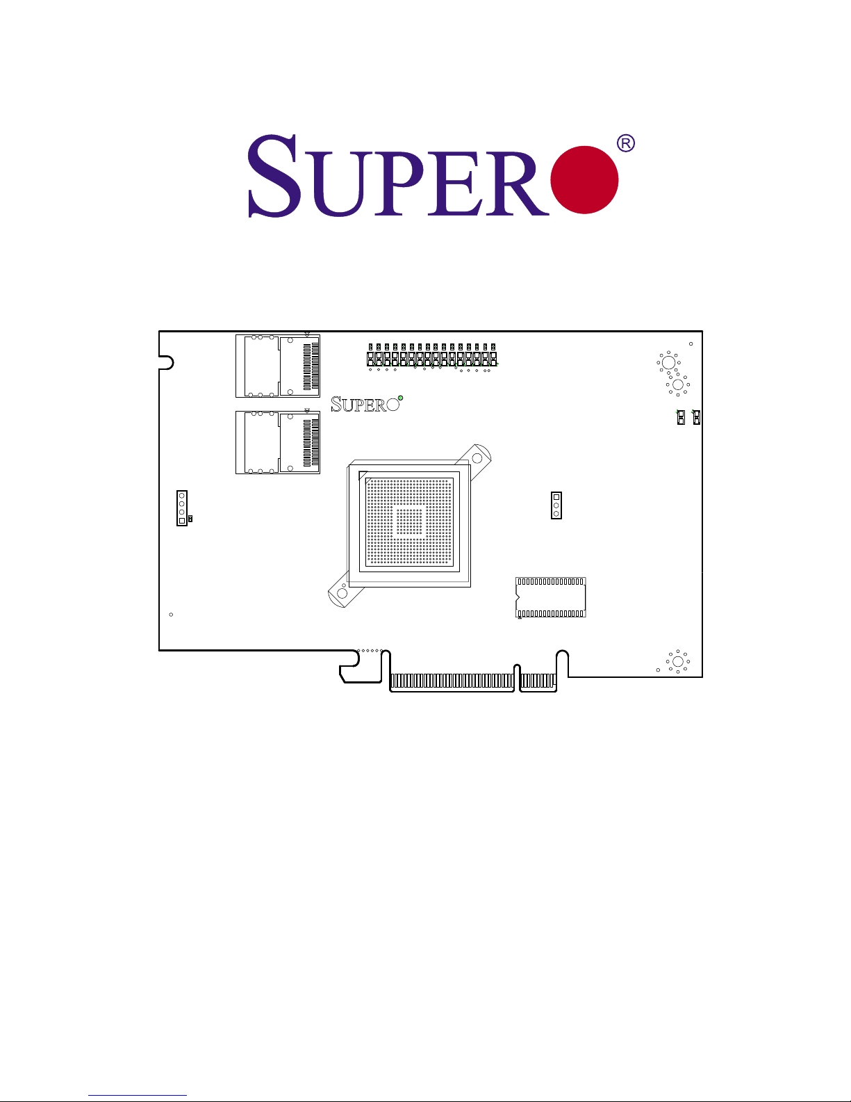
This manual is written for system integrators, PC technicians and knowledgeable
PC users who intend to integrate SuperMicro's AOC-USAS-L8i add-on card to
their system.
Product Features
The AOC-USAS-L8i add-on card offers the following features:
• UIO Form Factor.
• Dual Internal "ipass" cable ports.
• Multiple LED Activity/Failure indicators.
Operating Systems Supported
The AOC-USAS-L8i add-on card supports the following Operating Systems (OS):
• Windows 2000/Windows XP/Windows 2003
• Red Hat Enterprise Linux/SUSE Linux
An Important Note to Users
All images and layouts shown in this user's guide are based upon the latest PCB
Revision available at the time of publishing. The card you have received may or
may not look exactly the same as the graphics shown in this manual.

viii
Add-on Card User's Guide
Contacting SuperMicro
Headquarters
Address: SuperMicro Computer, Inc.
980 Rock Ave.
San Jose, CA 95131 U.S.A.
Tel: +1 (408) 503-8000
Fax: +1 (408) 503-8008
Email: marketing@supermicro.com (General Information)
support@supermicro.com (Technical Support)
Web Site: www.supermicro.com
Europe
Address: SuperMicro Computer B.V.
Het Sterrenbeeld 28, 5215 ML
's-Hertogenbosch, The Netherlands
Tel: +31 (0) 73-6400390
Fax: +31 (0) 73-6416525
Email: sales@supermicro.nl (General Information)
support@supermicro.nl (Technical Support)
rma@supermicro.nl (Customer Support)
Asia-Pacific
Address: SuperMicro, Taiwan
4F, No. 232-1, Liancheng Rd.
Chung-Ho 235, Taipei County
Taiwan, R.O.C.
Tel: +886-(2) 8226-3990
Fax: +886-(2) 8226-3991
Web Site: www.supermicro.com.tw
Technical Support:
Email: support@supermicro.com.tw
Tel: 886-2-8228-1366, ext.132 or 139

1-1
Safety Information and Technical Specifications
Chapter 1
Safety Guidelines
To avoid personal injury and property damage, carefully follow all the safety steps
listed below when accessing your system or handling the components.
1-1 ESD Safety Guidelines
Electric Static Discharge (ESD) can damage electronic components. To prevent dam-
age to your system, it is important to handle it very carefully. The following measures
are generally sufficient to protect your equipment from ESD.
• Use a grounded wrist strap designed to prevent static discharge.
• Touch a grounded metal object before removing a component from the anti
-
static bag.
• Handle the RAID card by its edges only; do not touch its components, periph
-
eral chips, memory modules or gold contacts.
• When handling chips or modules, avoid touching their pins.
• Put the card and peripherals back into their antistatic bags when not in use.
1-2 General Safety Guidelines
• Always disconnect power cables before installing or removing any components
from the computer.
• Disconnect the power cable before installing or removing any cables from the
system.
• Make sure that the add-on card is securely and properly installed on the moth
-
erboard to prevent damage to the system due to power shortage.
1-3 An Important Note to Users
• All images and layouts shown in this user's guide are based upon the latest
PCB Revision available at the time of publishing. The card you have received
may or may not look exactly the same as the graphics shown in this manual.

1-2
Add-on Card User's Guide
Notes
2-1
Safety Information and Technical Specifications
1 3
1
4
A
C
ACACACACACACACA
C
ACACACACACACACA
C
1 3
AF
AE
AD
AC
AB
AA
Y
W
V
T
R
P
N
M
L
K
J
U
H
G
F
E
D
C
B
A
2625242322212019181716151413121110987654321
1
4
A
C
ACACACACACACACA
C
ACACACACACACACA
C
PCBEDGE
ACA
C
PCBEDGE
Chapter 2
LED Indicators and Connectors
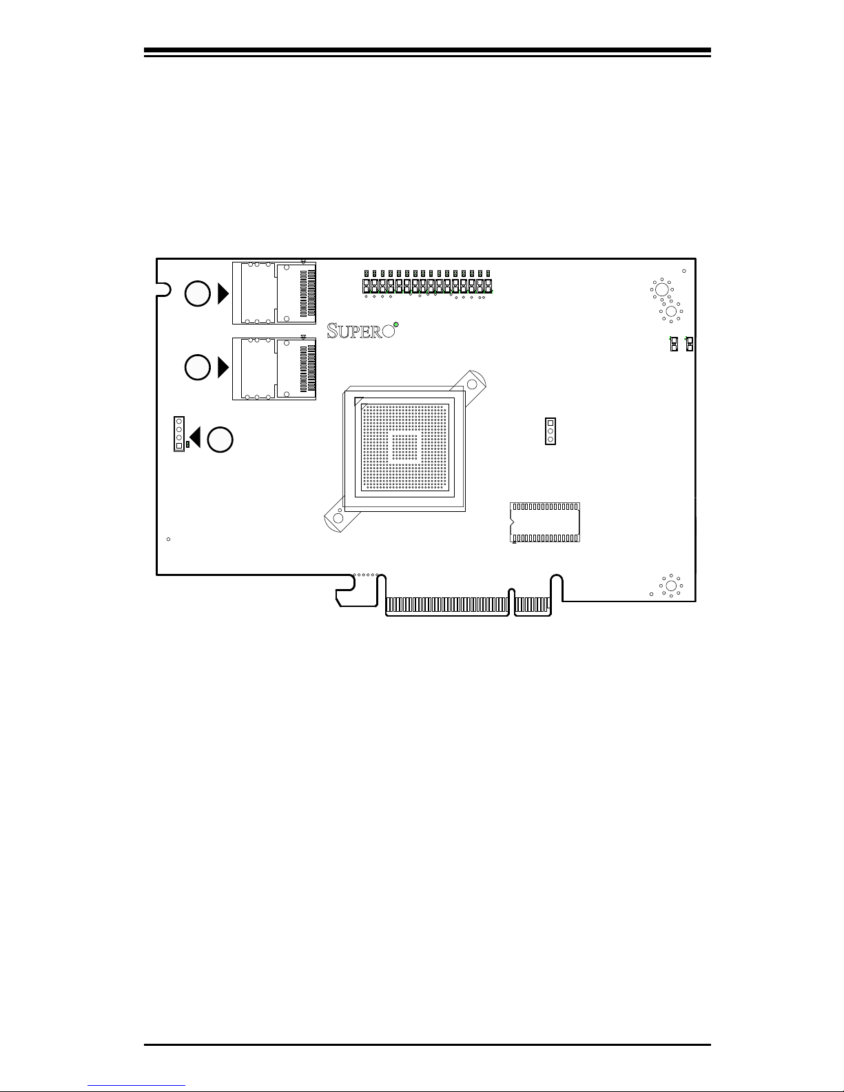
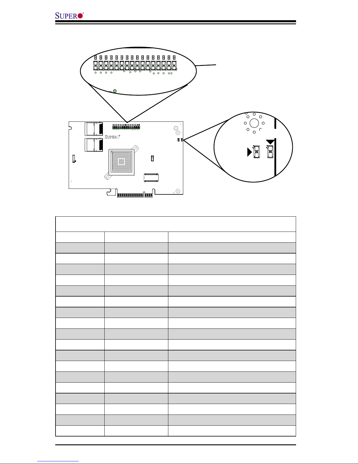
2-1 Front Connectors and Jumpers
#1. Internal SAS Connectors
#2. Front Panel LED Connector
1
2
Front Connectors
1
2-2
Add-on Card User's Guide
2-2 Front Connector and Pin Definitions
2. Active LED Connector
Allows the add-on card to display activity
and status using a standard LED panel.
1. Internal SAS Connectors
The Internal SAS ports connect to the
backplane allowing the motherboard to ac-
cess the hard drives and RAID capabilities.
Each connector supports up to 4 hard drives
allowing the add-on card to support a maxi-
mum of 8. (SAS 0-3 and SAS 4-7).
Use a single port SAS "ipass" cable (Super
Micro order number CBL - 0108L-02).
LED Connector
Pin Definitions
(U-12)
Pin# Definition
1 A - LED+
2 A - LED-
3 B - LED+
4 B - LED-
2-3
Safety Information and Technical Specifications
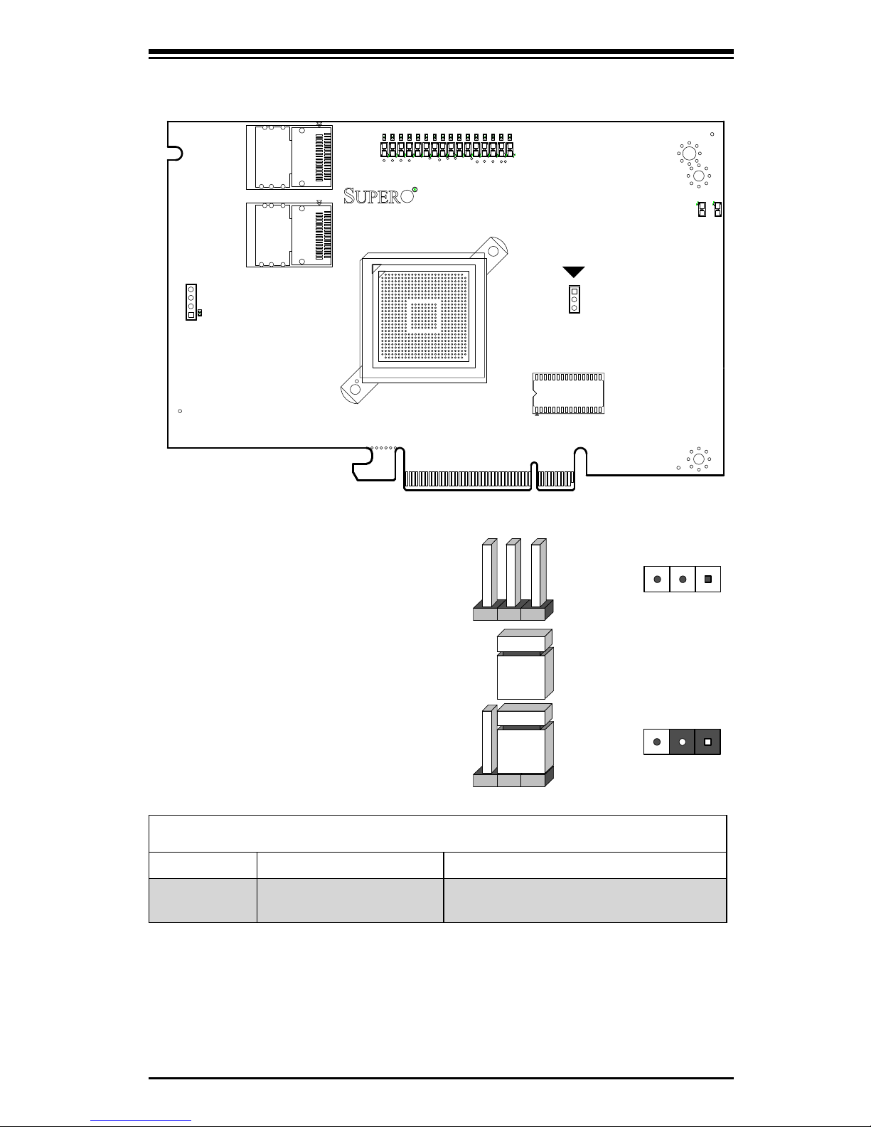
2-3 Front Jumper Locations and Pin Definitions
Jumper Settings
Jumper Jumper Settings Note
SWR5
1-2: Enabled
3: Disabled
Leave disabled for AOC-USAS-L8i
Explanation of Jumpers
To modify the operation of the backplane,
jumpers can be used to choose between
optional settings. Jumpers create shorts
between two pins to change the function
of the connector. Pin 1 is identified with
a square solder pad on the printed circuit
board. Note: On two pin jumpers, "Closed"
means the jumper is on and "Open" means
the jumper is off the pins.
Connector
Pins
Jumper
Setting
3 2 1
3 2 1
1 3
1
4
A
C
ACACACACACACACA
C
ACACACACACACACA
C
1 3
AF
AE
AD
AC
AB
AA
Y
W
V
T
R
P
N
M
L
K
J
U
H
G
F
E
D
C
B
A
2625242322212019181716151413121110987654321
1
4
A
C
ACACACACACACACA
C
ACACACACACACACA
C
PCBEDGE
ACA
C
PCBEDGE
SWR5
2-4
Add-on Card User's Guide
Front Pane LEDs
LED STATE SPECIFICATION
LED1 Flashing SAS Port Activity
LED2 Flashing Heartbeat and Fault
LNP0 ON Fault in HDD #0
LNP1 ON Fault in HDD #1
LNP2 ON Fault in HDD #2
LNP3 ON Fault in HDD #3
LNP4 ON Fault in HDD #4
LNP5 ON Fault in HDD #5
LNP6 ON Fault in HDD #6
LNP7 ON Fault in HDD #7
A0 Flashing Normal Activity in HDD #0
A1 Flashing Normal Activity in HDD #1
A2 Flashing Normal Activity in HDD #2
A3 Flashing Normal Activity in HDD #3
A4 Flashing Normal Activity in HDD #4
A5 Flashing Normal Activity in HDD #5
A6 Flashing Normal Activity in HDD #6
A7 Flashing Normal Activity in HDD #7
LED INDICATORS
POWER LEDS
LNP0 - LNP7
A0 - A7
1 3
1
4
A
C
A
C
A
C
A
C
A
C
A
C
A
C
A
C
A
C
A
C
A
C
A
C
A
C
A
C
A
C
A
C
A
C
1 3
AF
AE
AD
AC
AB
AA
Y
W
V
T
R
P
N
M
L
K
J
U
H
G
F
E
D
C
B
A
2625242322212019181716151413121110987654321
1
4
A
C
A
C
A
C
A
C
A
C
A
C
A
C
A
C
A
C
A
C
A
C
A
C
A
C
A
C
A
C
A
C
A
C
PCBEDGE
A
C
A
C
PCBEDGE
A
C
A
C
A
C
A
C
A
C
A
C
A
C
A
C
A
C
A
C
A
C
A
C
A
C
A
C
A
C
A
C
A
C
A
C
A
C
A
C
A
C
A
C
A
C
A
C
A
C
A
C
A
C
A
C
A
C
A
C
A
C
A
C
A
C
A
C
A
C
A
C
LED1
LED2
2-5
Safety Information and Technical Specifications
RAID Minimum Drive Requirements
RAID Minimum Hard Drives
RAID 0 2
RAID 1 2
RAID 10 4 (2 RAID 1 Arrays)
Use the following chart to determine the minimum number of hard drives needed
to set up a RAID environment.

2-6
Add-on Card User's Guide
Notes

3-1
Safety Information and Technical Specifications
Chapter 3
Driver Installation
The MegaRAID BIOS Configuration Utility (CU) is used to configure disk arrays and
logical drives and to do other configuration tasks in a pre-bootenvironment.
3-1 Performing a Quick Configuration
This section provides high level instructions for quickly configuring arrays and logical
drives with the MegaRAID BIOS CU. These instructions are intended for users that
are familiar with configuration utilities and tools. Refer to Section 3-2, “Configuring
Arrays and Logical Drives,” for detailed configuration instructions. To ensure the best
performance, select the optimal RAID level for the logical drive you create.
Important: It is recommended that you do not use both SAS and SATA drives in the
same array. Using different drive interfaces in this way could cause unpredictable be
-
havior, decreased performance, an increased error count, and decreased MTBF.
Perform the following steps to configure arrays and logical drives using the Mega
-
RAID BIOS CU:
1. Boot the system.
2. Start the MegaRAID BIOS CU by pressing Ctrl+H.
3. Select Configure from the Management Menu.
4. Select a configuration method from the Configuration menu (Easy Configuration,
New Configuration, or View/Add Configuration).
5. Create arrays using the available physical drives.
6. Define the logical drive(s) using the space in the arrays.
7. Initialize the new logical drive(s).
3-2
Add-on Card User's Guide
3-2 Configuring Arrays and Logic Drives
This section provides detailed instructions for configuring arrays and logical drives
with the MegaRAID BIOS CU. LSI recommends that you use drives with the same
capacity when you create a storage configuration. If you use drives with different
capacities in one array, the CU limits each drive to the capacity of the smallest
drive.
The number of physical drives in a specific array determines the possible RAID
levels that you can implement with the array.
• RAID 0 requires from one to eight physical drives.
• RAID 1 requires two physical drives.
• RAID 10 requires four, six, or eight physical drives.
Starting the MegaRAID BIOS CU
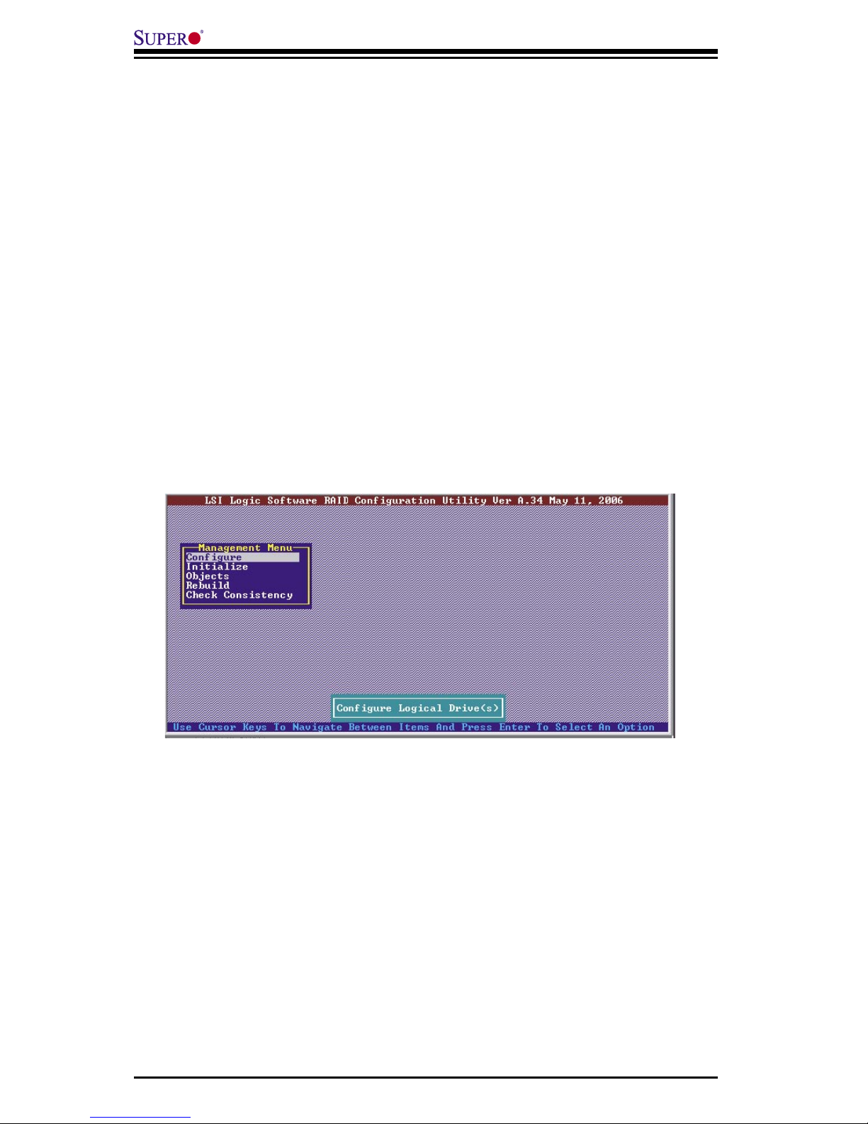
Follow these steps to start the MegaRAID BIOS CU:
1. During boot-up, wait for the following message to appear on the screen:
Press Ctrl-H to run LSI Logic Software RAID Setup Utility
2. When you see this message, hold down the Ctrl key while pressing the H key.
The main menu for the Configuration Utility appears, as shown in Figure 3-1.
Figure 3-1: Configuration of the Main Utility

3-3
Safety Information and Technical Specifications
Note: When you start the MegaRAID BIOS CU by pressing Ctrl-H the Configuration
Manager Module of the BIOS allocates three segments of memory using either PMM
or conventional memory: these are the Destination Segment, Scratch Segment, and
Read Write Buffer Segment. If the three segments are not available the BIOS hooks
INT19h and loads the CU at the fixed segments 5000:0 (Destination Segment),
6000:0 (Scratch Segment) and 7000:0 (Read Write Buffer Segment) after POST.
Using Easy Configuration
When you select the Easy Configuration option, the CU creates one or more arrays
from the available physical drives and configures each array as a single logical drive.
If logical drives have already been configured, the CU does not change their con-
figuration. Follow these steps to create a logical drive using Easy Configuration:
1. Select Configuration→ Easy Configuration from the Management Menu. A list of
available (READY) physical drives appears.
2. Use the arrow keys to select the physical drives to include in the array.
3. Press the spacebar to add each selected physical drive to the new array.
When you select a physical drive, its status changes from READY to ONLIN
A[array number]-[drive number]. For example, ONLIN A00-01 means array 0,
disk drive 1.
4. To create a global hotspare drive, highlight a READY disk drive and press F4.
Then select Yes from the pop-up menu.
5. To define multiple arrays, select all the drives you want for the first array, then
press Enter to start selecting drives for the second array, and so on.
6. When you have selected drives for all desired arrays, press F10.
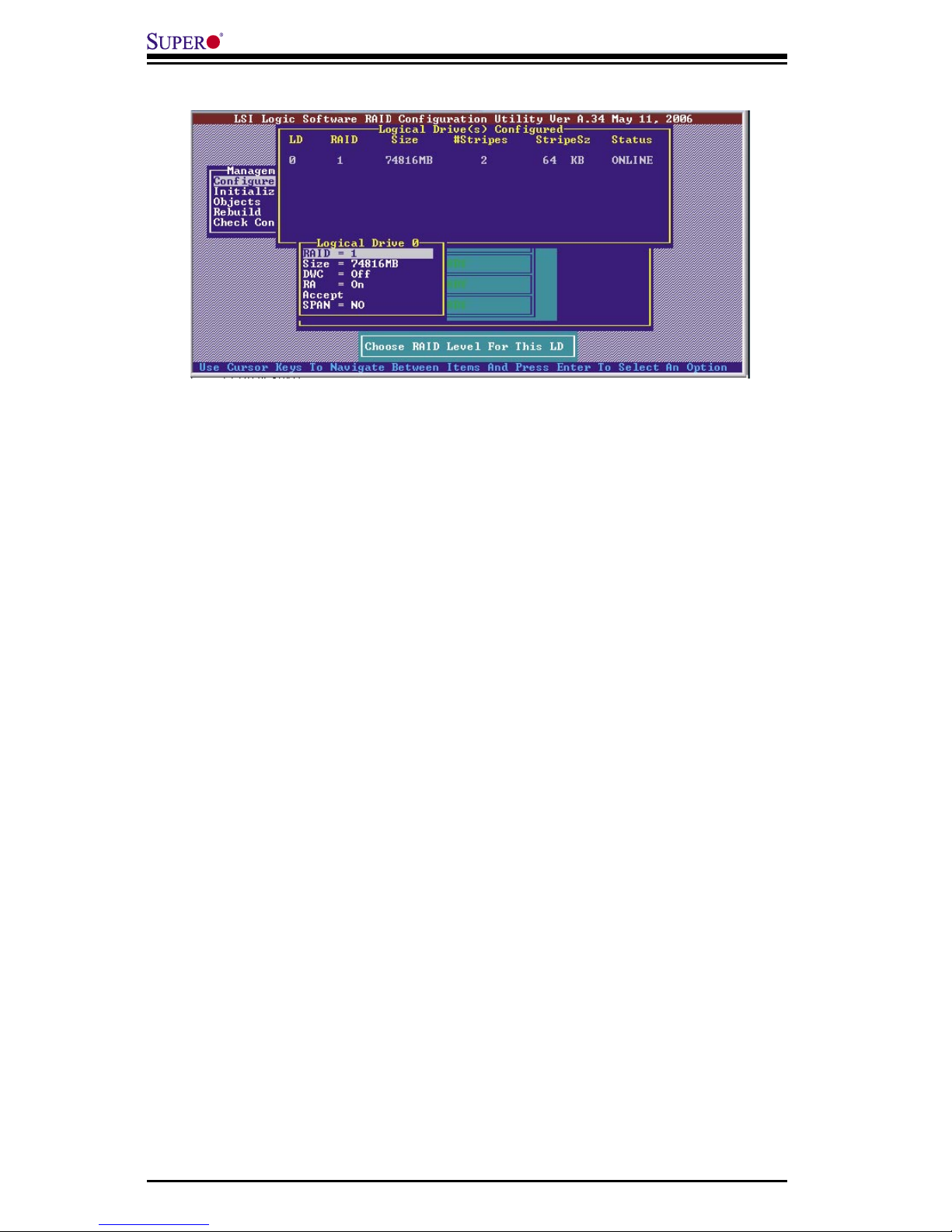
7. Press the spacebar to select an array.
The Logical Drive Configuration screen appears, as shown in Figure 3-2. This
screen shows the logical drive number, RAID level, logical drive size, number of
stripes in the physical array, stripe size, and state of the logical drive.
3-4
Add-on Card User's Guide
Figure 3-2: Logical Drive Configuration
8. Highlight RAID and press Enter.
The available RAID levels for the current logical drive are displayed.
9. Select a RAID level for the logical drive and press Enter.
10. (Optional) Change the drive’s default Write Cache and Read Ahead policies (see
Section 3-3, “Setting the Hard Disk Write Cache and Read Ahead Policies”).
11. When you have finished defining the current logical drive, select Accept and
press Enter.
12. Save the configuration when prompted, and press any key to return to the
Management Menu.
13. Initialize the new logical drive(s). (See Section 3 “Initializing Logical Drives,” for
detailed instructions.)
Using New Configuration and View/Add Configuration
When you select the New Configuration menu option, the CU deletes the existing
arrays and logical drives and replaces them with the new configuration that you
specify. The View/Add Configuration menu option lets you view the existing con-
figuration or add to the existing configuration, if possible.
Caution: If you want to keep the existing data on the storage configuration, use
View/Add Configuration instead of New Configuration.
 Loading...