

SUPER
AOC-SIM1U-3B+
AOC-SIM1U-3B
AOC-SIM1U-3D
®
SIM1U-3B
AOC-SIM1U-3B(+)
SIM1U-3D
Daughter Card:AOC-SIM1U-3D
USER'S GUIDE
Rev. 1.0b

AOC-SIM1U-3B(+)/SIM1U-3D User's Guide
The information in this User’s Guide has been carefully reviewed and is believed to be accurate.
The vendor assumes no responsibility for any inaccuracies that may be contained in this document,
makes no commitment to update or to keep current the information in this user's guide, or to notify
any person or organization of the updates.
Please Note: For the most up-to-date version of this user's guide, please see our
web site at www.supermicro.com.
SUPERMICRO COMPUTER reserves the right to make changes to the product described in this
user's guide at any time and without notice. This product, including software, if any, and documentation may not, in whole or in part, be copied, photocopied, reproduced, translated or reduced to any
medium or machine without prior written consent.
IN NO EVENT WILL SUPERMICRO COMPUTER BE LIABLE FOR DIRECT, INDIRECT, SPECIAL,
INCIDENTAL, OR CONSEQUENTIAL DAMAGES ARISING FROM THE USE OR INABILITY TO
USE THIS PRODUCT OR DOCUMENTATION, EVEN IF ADVISED OF THE POSSIBILITY OF
SUCH DAMAGES. IN PARTICULAR, THE VENDOR SHALL NOT HAVE LIABILITY FOR ANY
HARDWARE, SOFTWARE, OR DATA STORED OR USED WITH THE PRODUCT, INCLUDING THE
COSTS OF REPAIRING, REPLACING, INTEGRATING, INSTALLING OR RECOVERING SUCH
HARDWARE, SOFTWARE, OR DATA.
Any disputes arising between manufacturer and customer shall be governed by the laws of Santa
Clara County in the State of California, USA. The State of California, County of Santa Clara shall
be the exclusive venue for the resolution of any such disputes. Supermicro's total liability for all
claims will not exceed the price paid for the hardware product.
WARNING: Handling of lead solder materials used in this
product may expose you to lead, a chemical known to
the State of California to cause birth defects and other
reproductive harm.
User's guide Revision: Rev. 1.0b
Release Date: July 5, 2007
Unless you request and receive written permission from SUPER MICRO COMPUTER, Inc., you
may not copy any part of this document.
Information in this document is subject to change without notice. Other products and companies
referred to herein are trademarks or registered trademarks of their respective companies or mark
holders.
Copyright © 2007 by SUPER MICRO COMPUTER, INC.
All rights reserved.
Printed in the United States of America
1-2

Chapter 1: Introduction
Table of Contents
Chapter I: Introduction ............................................................................. 1-4
1.1 Overview .................................................................................................... 1-4
1.2 IPMI Version 2.0 ........................................................................................ 1-5
1.3 Product Features ...................................................................................... 1-5
1.4 Checklist ................................................................................................... 1-5
1.5 An Important Note to the User ................................................................ 1-5
1.6 Contacting Supermicro ............................................................................ 1-6
Chapter 2: Technical Specifi cations and Hardware Installation ..........2-1
2.1 AOC-SIM1U-3B(+) Component Locations .............................................. 2-2
2.1.1 Front Component and LED Descriptions ................................................ 2-2
2.1.2 Rear Component and LED Locations ..................................................... 2-3
2.1.3 Rear LED Descriptions ............................................................................ 2-3
2.2 AOC-SIM1U-3D Component Locations ................................................... 2-4
2.2.1 Front Components ................................................................................... 2-4
2.2.2 LAN Ports and LED Indicators ................................................................ 2-5
2.3 Block Diagram .......................................................................................... 2-6
2.4 Installing the AOC-SIM1U-3B(+) Add-On Card ...................................... 2-7
2.4.1 Safety Guidelines .................................................................................... 2-7
2.4.2 SIM1U-3B(+) Slot Locations .................................................................... 2-8
Chapter 3: Software Application and Usage .......................................... 3-1
3.1 Home Page ................................................................................................ 3-3
3.2 Functions Listed On the Home Page ..................................................... 3-5
3.2.1 Remote Control ....................................................................................... 3-5
3.2.2 Virtual Media ............................................................................................ 3-7
3.2.3 System Health ........................................................................................3-11
3.2.4 User Management ................................................................................. 3-17
3.2.5 KVM Settings ......................................................................................... 3-21
3.2.6 Device Settings ...................................................................................... 3-25
3.2.7 Maintenance .......................................................................................... 3-38
3.3 Remote Console Main Page .................................................................. 3-42
3.3.1 Remote Console Options ...................................................................... 3-43
Chapter 4: Frequently Asked Questions ................................................ 4-1
1-3

AOC-SIM1U-3B(+)/SIM1U-3D User's Guide
Chapter 1
Introduction
This user's guide is written for system integrators, PC technicians and
knowledgeable PC users who intend to integrate Supermicro's unique IPMI 2.0
Management Utility with support of KVM-over-LAN* into their systems. It provides
detailed information for the application and use of the AOC-SIM1U-3B(+) that
supports remote access for system monitoring, diagnosis and management. With
the most advanced technologies built-in, the AOC-SIM1U-3B(+) and its daughter
card AOC-SIM1U-3D offer a complete, effi cient, and cost-effective remote server
management. (*Note: KVM-over-LAN support is available on the AOC-SIM1U-3B+
only.)
1.1 Overview
The AOC-SIM1U-3B(+), used in conjuction with its daughter card AOC-SIM1U-3D,
offers a highly effi cient, highly compatible and easy-to-use IPMI card set that al-
lows the user to take advantage of the BMC, a baseboard management controller
installed on a server motherboard, and the IPMIView, an IPMI-compliant manage-
ment application software stored in a PC, to provide serial links between the main
processor and other system components, allowing for network interfacing via remote
access. With an independent Raritan KIRA100 processor built-in, the AOC-SIM1U-
3B(+)/3D IPMI card set provides the user with a solution to ease the complex and
expensive systems, allowing an administrator to access, monitor, diagnose and
manage network interfacing anywhere, anytime.
1.2 IPMI Version 2.0
The AOC-SIM1U-3B(+)/3D supports the functionality of IPMI Version 2.0. The key
features include the following:
Supports IPMI 2.0 over LAN
•
Supports Serial over LAN
•
Supports KVM over LAN (*For the AOC-SIM1U-3B+ only)
•
Supports Virtual Media over LAN
•
Supports LAN Alerting-SNMP Trap
•
Supports Event Log
•
Offers OS (Operating System) Independency
•
Provides remote Hardware Health Monitoring via IPMI. Key features include
•
the following:
Temperature monitoring
•
Fan speed monitoring
•
Voltage monitoring
•
1-4

Chapter 1: Introduction
Power status monitoring, chassis intrusion monitoring
•
Remote power control to power-on, power-off or reboot a system
•
Remote access to text-based, graphic-based system information,
•
including BIOS confi gurations and OS operation information (KVM)
Remote management of utility/software applications
•
Provides Network Management Security via remote access/console redirec-
•
tion. Key features include:
User authentication enhancement
•
Encryption support enhancement, allowing for password confi gura-
•
tion security to protect sensitive data transferring via Serial over
LAN
Supports the following Management tools: IPMIView, CLI (Command Line
•
Interface)
Supports RMCP & RMCP protocols
•
1.3. Product Features
(a) The AOC-SIM1U-3B(+)
• AOC-SIM1U-3B(+): Slim size (4.4" W x 1.3" H) (111.76 mm W x 25.41 mm H)
• Supports IPMI over LAN
• Supports 1U and above
(b) The AOC-SIM1U-3D
• AOC-SIM1U-3D: Low Profi le (3.2" W x 2.4" H) (81.28 mm W x 60.96 mm H)
• Supports IPMI with a 3rd data dedicated LAN
• Supports a third DATA LAN
1.4 Checklist
If your shipping package came with missing or damaged parts, please contact
Supermicro's Tech. Support. Please refer to the following checklist when
contacting us.
i. AOC-SIM1U-3B(+)
ii. CDR-SIMIPMI: One Installation CD
iii. White Box with Correct Barcode Label (showing AOC-SIM1U-3B(+)).
1.5 An Important Note to the User
The graphics shown in this user's guide were based on the latest PCB Revision
available at the time of publishing of this guide. The SIM1U-3B(+) card you’ve
received may or may not look exactly the same as the graphics shown in this
user's guide.
1-5

AOC-SIM1U-3B(+)/SIM1U-3D User's Guide
1.6 Contacting Supermicro
Headquarters
Address: SuperMicro Computer, Inc.
980 Rock Ave.
San Jose, CA 95131 U.S.A.
Tel: +1 (408) 503-8000
Fax: +1 (408) 503-8008
Email: marketing@supermicro.com (General Information)
support@supermicro.com (Technical Support)
Web Site: www.supermicro.com
Europe
Address: SuperMicro Computer B.V.
Het Sterrenbeeld 28, 5215 ML
's-Hertogenbosch, The Netherlands
Tel: +31 (0) 73-6400390
Fax: +31 (0) 73-6416525
Email: sales@supermicro.nl (General Information)
support@supermicro.nl (Technical Support)
rma@supermicro.nl (Customer Support)
Asia-Pacifi c
Address: SuperMicro, Taiwan
4F, No. 232-1 Liancheng Road
Chung-Ho 235, Taipei Hsien, Taiwan, R.O.C.
Tel: +886-(2) 8226-3990
Fax: +886-(2) 8226-3991
Web Site: www.supermicro.com.tw
Technical Support:
Email: support@supermicro.com.tw
1-6
Chapter 2: Technical Specifi cations and Installation
Chapter 2
Technical Specifi cations and Hardware
Installation
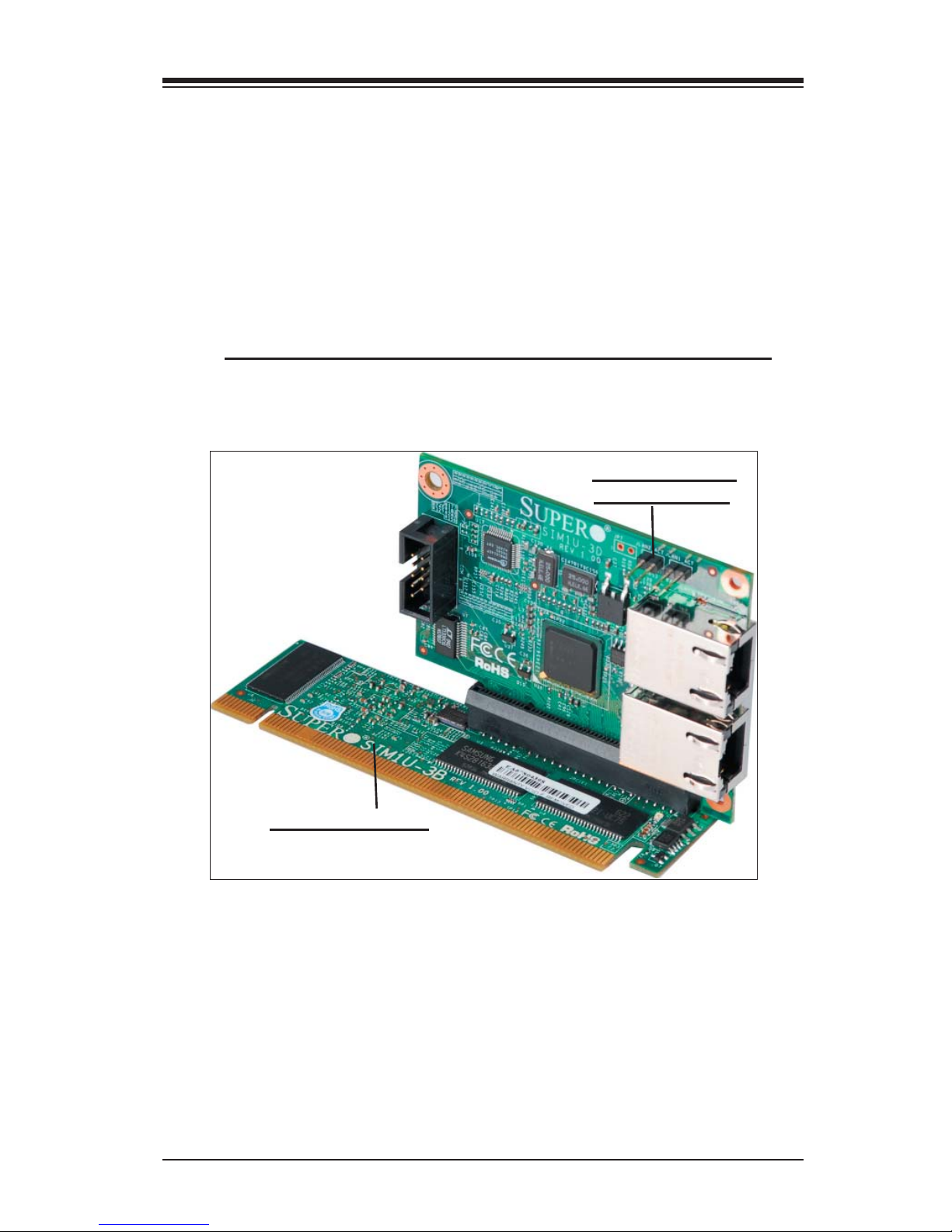
The AOC-SIM1U-3B(+) and its Daughter Card AOC-SIM1U-3D
Daughter Card:
AOC-SIM1U-3D
AOC-SIM1U-3B(+)
2-1
AOC-SIM1U-3B(+)/SIM1U-3D User's Guide
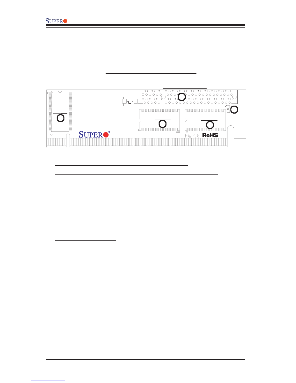
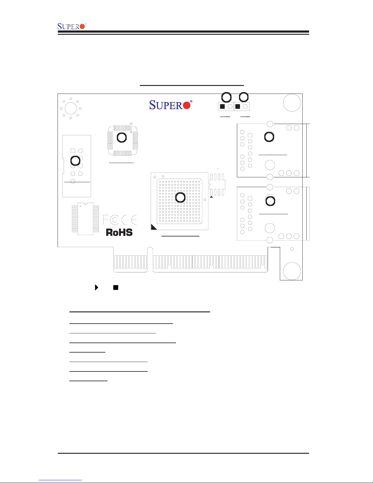
2.1 AOC-SIM1U-3B(+) Component Locations
AOC-SIM1U-3B(+) Front View
JPCIE: PCI-Exp. Slot
1
V-RAM
3
SDRAM
4
SDRAM
4
2
SIM1U-3B
2.1.1 Front Components and LED Descriptions
1. JPCIE: PCI-Express Slot for the Daughter Card AOC-SIM1U-3D
Plug the AOC-SIM1U-3D card into this slot to provide Dedicated LAN and a 3rd
Data LAN Port support to the AOC-SIM1U-3B(+).
2. D3: Standby Power LED Indicator
When this LED is on, the standby power is
on. Be sure to remove power cables before
installing or removing components.
3. VRAM (64Mb/166MHz)
4. SDRAM (128Mb/133MHz)
2-2
Chapter 2: Technical Specifi cations and Installation
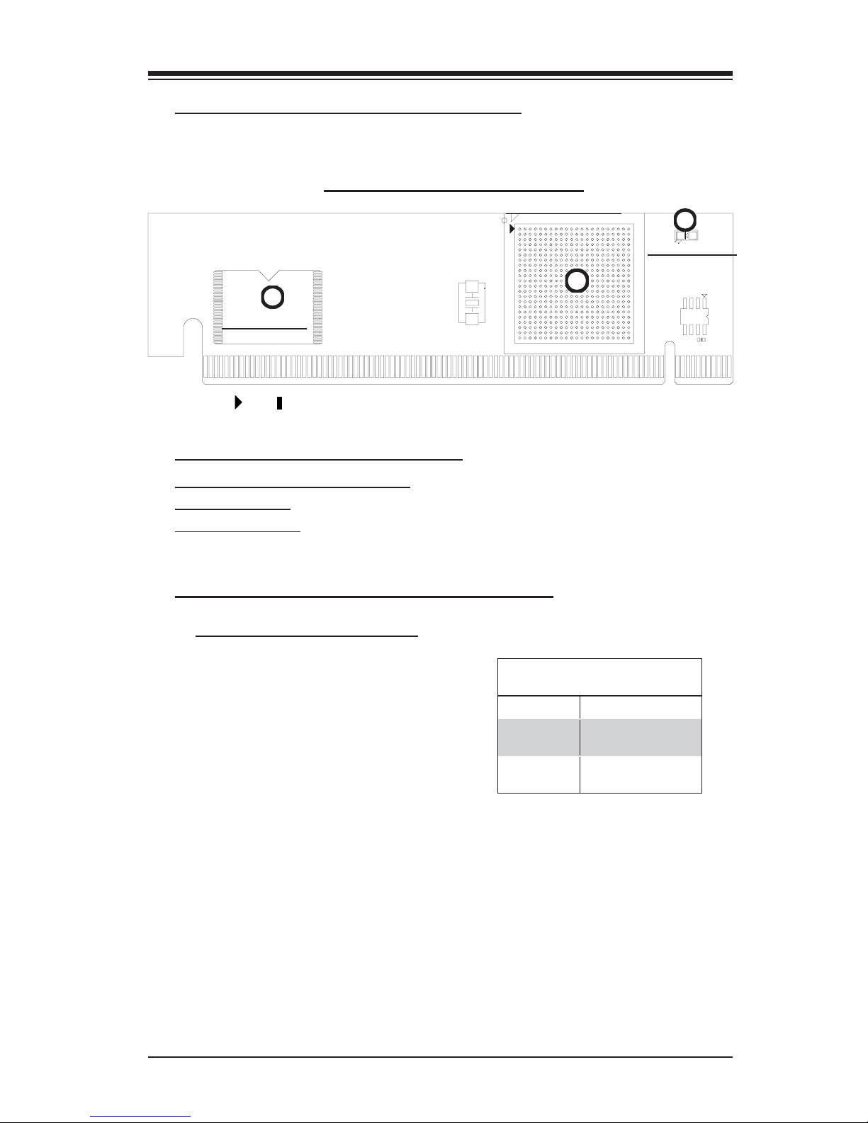
2.1.2 Rear Component and LED Locations
AOC-SIM1U-3B(+) Rear View
Kira 100 Processor
2
Flash Memory
(*Note: " " or " " indicates Pin 1.)
AOC-SIM1U-3(+) Rear Components
3
Heartbeat LED
1
1. The Raritan Kira 100 Processor
2. Flash Memory
3. Heartbeat LED
2.1.3. AOC-SIM1U-3B(+) Rear LED Description
#3 Heartbeat LED Indicator
Heartbeat LED (marked #3 above), lo-
cated on the rear side of the AOC-SIM1U-
3B(+) card, indicates the functionality and
activity of the add-on card. When the
Heartbeat LED blinks, the AOC-SIM1U-
3B(+) is active. However, after each AC
power-on or reset, the Heartbeat LED is
off for about a minute. Then, the Heart-
beat LED will be on again to indicate that
the AOC-SIM1U-3B(+) is active. See the
table on the right for details.
On (Blinking) SIM1U-3B(+): active
Off (for 1
minute)
Off (Continuously)
Heartbeat LED
Loading Firmware
SIM1U-3B(+) is not
active
2-3
AOC-SIM1U-3B(+)/SIM1U-3D User's Guide
2.2 AOC-SIM1U-3D Component Locations
AOC-SIM1U-3D Front View
5
6
SIM1U-3D
4
7
COM Port
(*Note: " " or " " indicates Pin 1.)
PHY LAN
1
LAN Controller
JP6
JP5
2
LAN Port 1
3
LAN Port 2
2.2.1 AOC-SIM1U-3D Front Components
1. Giga-bit Ethernet LAN Controller
2. LAN Port 1 (for IPMI/KVM) (*Note)
3. LAN Port 2 (for the 3rd LAN Data) (*Note)
4. PHY LAN
5. JP5 (LAN Port 1 Active)
6. JP6 (LAN Port 2 Active)
7. COM port
(*Note: See Page 2-4 for details.)
2-4

Chapter 2: Technical Specifi cations and Installation
2.2.2 AOC-SIM1U-3D LAN Ports and LAN LED Indicators
#2/#3 LAN Port 1 and LAN Port 2
Two G-bit Ethernet ports are located on the
Daughter Card AOC-SIM1U-3D. LAN Port
1(JLAN1) provides the IPMI/KVM connec-
tions to the the AOC-SIM1U-B(+). LAN Port
2(JLAN2) offers the additional 3rd Data LAN.
JLAN1JLAN2
These ports accept RJ45 type cables.
LAN LED Indicators
There are two LAN LED Indicators located
on each LAN port. The green LED indicates
activity, while the power LED may be green,
amber, or off to indicate the speed of the
Ethernet connection. See the tables on the
right for more information.
Activity
LED
Link LED
LAN Activity Indicator
Color Status Defi nition
Amber Flashing Active
LAN Link Indicator
LED Color Defi nition
Off No Connection or 10 Mbps
Green 100 Mbps
Amber 1000 Mbps
2-5
AOC-SIM1U-3B(+)/SIM1U-3D User's Guide
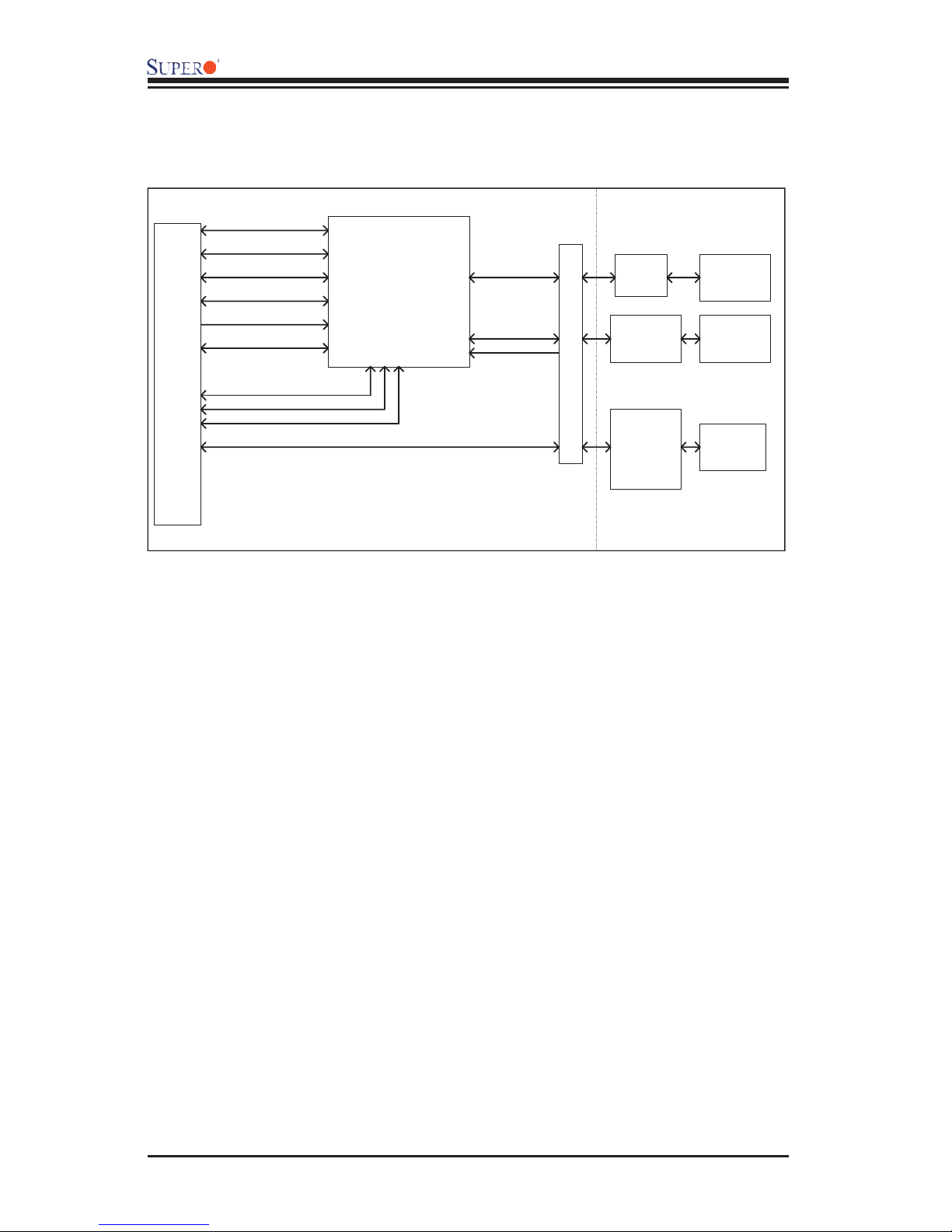
2.3 Block Diagram
UART I nte rface
USB Interface
LPC Interface
FML Interface
DVO interface
RMI I
Mother Board SMDATA
Mother Board SMCLK
IPMI 200 Connector
Mother B oard SMALT#
KIRA100
PRSNT#
PCI 32/33MHz Interface
PCI-Express x8 Connector
UART
Ethernet PHY
Intel 82541 PI
DB9 Header
RJ45
Dedicated LAN
3rd Data LAN
SIM1U-3D
2-6

Chapter 2: Technical Specifi cations and Installation
2.4 Installing the AOC-SIM1U-3B(+) Add-On Card
2.4.1 Safety Guidelines
To avoid personal injury and property damage, please carefully
follow all the safety steps listed below when installing the AOC-
SIM1U-3B(+) into your system.
ESD Safety Guidelines
Electric Static Discharge (ESD) can damage electronic com ponents. To prevent dam-
age to your system, it is important to handle it very carefully. The following measures
are generally suffi cient to protect your equipment from ESD.
• Use a grounded wrist strap designed to prevent static discharge.
• Touch a grounded metal object before removing a component from the antistatic
bag.
• Handle the add-on card by its edges only; do not touch its components, peripheral
chips, memory modules or gold contacts.
• When handling chips or modules, avoid touching their pins.
• Put the card and peripherals back into their antistatic bags when not in use.
General Safety Guidelines
• Always disconnect power cables before installing or removing any components
from the computer.
• Use only the correct type of bracket for the add-on card.
• Disconnect the power cable before removing any cable from the add-on card.
• Make sure that the SIM1U-3B(+) add-on card is securely seated in the
SIM1U-3B(+) slot to prevent damage to the system due to power shortage.
For SIM1U-3B(+) slot locations, please refer to Section 2.4.2.
SMC Motherboards with SIM1U-3B(+) support
The following Supermicro's motherboards support the AOC-SIM1U-3B(+).
1. The X7DBX-8/X7DBX-i Series
1. The X7DBP-8/X7DB-P-i Series
2-7
AOC-SIM1U-3B(+)/SIM1U-3D User's Guide
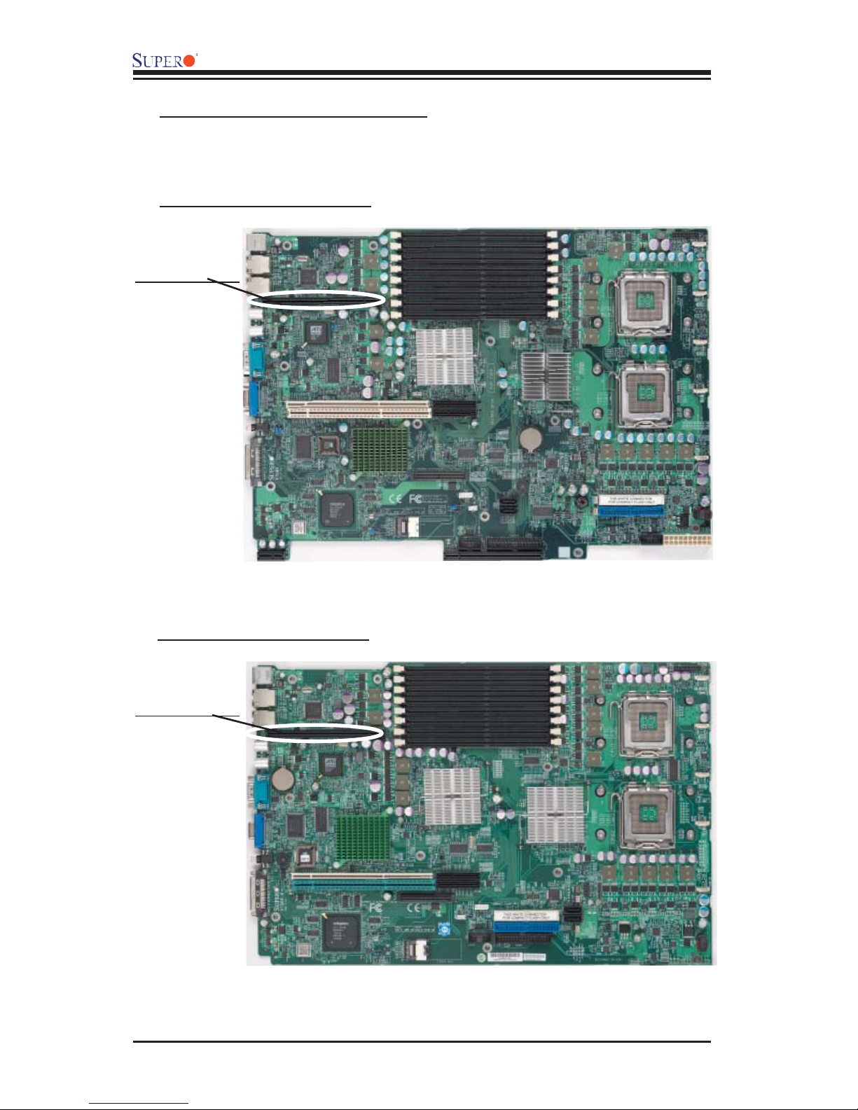
2.4.2 SIM1U-3B(+) Slot Locations
To properly use the AOC-SIM1U-3B(+), be sure to install it in the right slot. Refer
to the MB layouts below for SIM1U-3B(+) slot locations.
1. The X7DBX-8/X7DX-i Series
SIM1U-3B(+) Slot
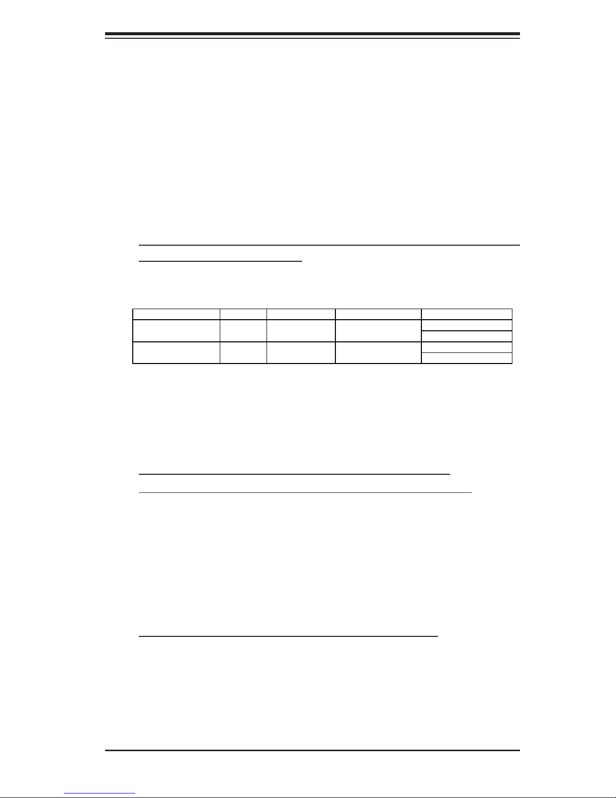
2. The X7DBP-8/X7DP-i Series
SIM1U-3B(+) Slot
2-8
Chapter 3: Software Application and Usage
Chapter 3
Software Application and Usage
With an independent I/O processor embedded in Raritan's Kira 100 RISC System
Chip, the AOC-SIM1U-3B(+)/SIM1U-3D Add-On Card allows the user to access,
monitor, manage and interface with systems that are in remote locations via
LAN. The necessary utilities for the access and confi guration of the add-on
card are included on the Supermicro bootable CDs that came with your card.
This section provides information on the confi guration and the access of the
IPMI card on the network. (*Note: KVM-over-LAN support is available on the
AOC-SIM1U-3B+ only.)
Using the IPMICFG Utility to Confi gure IP/MAC Addresses and
other IPMI Network Settings
1. Run the ipmicfg utility from the bootable CD that came with your shipment.
2. Refer to the table below to confi gure the IP/MAC addresses.
Board IPMI MAC IP Communication Thru
X7 Series
H8 DDR2 MEMORY
3. Follow the instructions given in the Readme.txt fi le to confi gure Gateway
IP/Netmask IP addresses, to enable/disable DHCP and to confi gure other IPMI
settings.
SIM1U IPMI Card Available IP/DHCP
SIM1U IPMI Card Available IP/DHCP
Dedicated LAN
LAN1 on MB
Dedicated LAN
LAN1 on MB
*Note: The Readme.txt fi le is included in the CD that came with your shipment.
A copy of the Readme.txt fi le, dated 07/05/2007, is also included below.
IPMICFG Version 1.04 Copyright 2007 SuperMicro Computer Inc.
Usage: IPMICFG Parameters (Example: IPMICFG -m 192.168.1.123)
-m Show IP and MAC
-m IP Set IP (format: ###.###.###.###)
-a MAC Set MAC (format: ##:##:##:##:##:##)
-k Show Subnet Mask
-k Mask Set Subnet Mask (format: ###.###.###.###)
-dhcp on Enable the DHCP
-dhcp off Disable the DHCP
-g Show Gateway IP
-g IP Set Gateway IP (format: ###.###.###.###)
To Access the SIM1U/SIM1U+ Card from a Computer
1. Choose a computer that is connected to the same network and open the
browser.
2. Type in the IP address of each server that you want to connect in the address
bar in your browser.
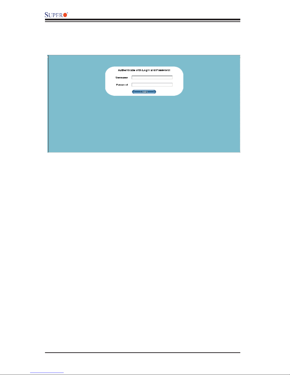
3. Once the connection is made, the Log In screen as shown on the next page
displays.
3-1
AOC-SIML1U-3B(+)/AOC-SIM1U-3D User's Guide
To Log In
Once you are connected to the remote server, the following Log In screen
displays.
1. Type in your Username in the "Username" box.
2. Type in your Password in the "Password" box and click on "Login."
(*Note: The default username is ADMIN. The default password is ADMIN.)
3. The Home Page will display as follows:
3-2
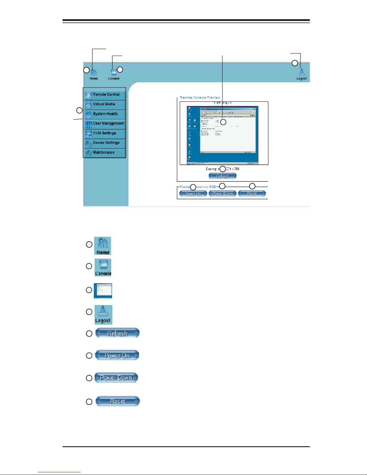
3.1 Home Page
Chapter 3: Software Application and Usage
1
9
Function Keys
Home
Console
2
Remote Console Screen
3
5
6
7
Logout
4
8
3.1.1 Buttons from the Home Page
1
2
3
4
5
6
7
8
Home: Click this icon to return to the Home Page.
Console: Click this icon to go to the Remote Console Screen.
Remote Console Screen: Displayed in the window is Remote
Console Screen. Click on this window to go to the Remote Console
Screen.
Logout: Click on this icon to log out.
Refresh: Click on this icon to refresh the screen of the
remote console preview.
Power On: Click on this icon to power on the system of the
remote host.
Power Down: Click on this icon to power down the system
of the remote host.
Reset: Click on this icon to reset the remote host.
3-3
AOC-SIML1U-3B(+)/AOC-SIM1U-3D User's Guide
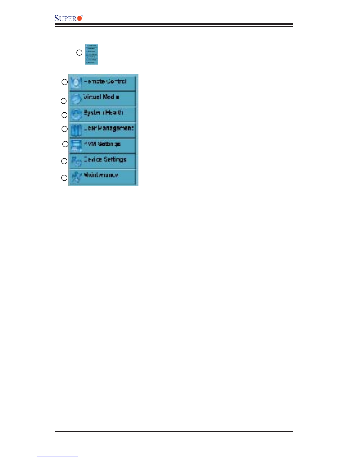
3.1.2 Function Keys from the Home Page
9
Click on these function keys to use the functions as specifi ed below.
1
1. Remote Control: Click on this icon for remote access
and management of Video Console Redirection.
2. Virtual Media: Click on this icon to use virtual remote
2
3
4
5
media devices.
3. System Health: Click on this icon to view and manage health monitoring for remote systems
4. User Management: Click on this icon for User Management.
5. KVM Settings: Click on this icon to confi gure keyboard, Video and mouse settings.
6
6. Device Settings: Click on this icon to confi gure
device settings.
7
7. Maintenance: Click on this icon to access, diagnose
and manage hardware devices
(*Note: Please see the next page for details on the functions specifi ed above.)
3-4
Chapter 3: Software Application and Usage
3.2 Functions Listed on the Home Page
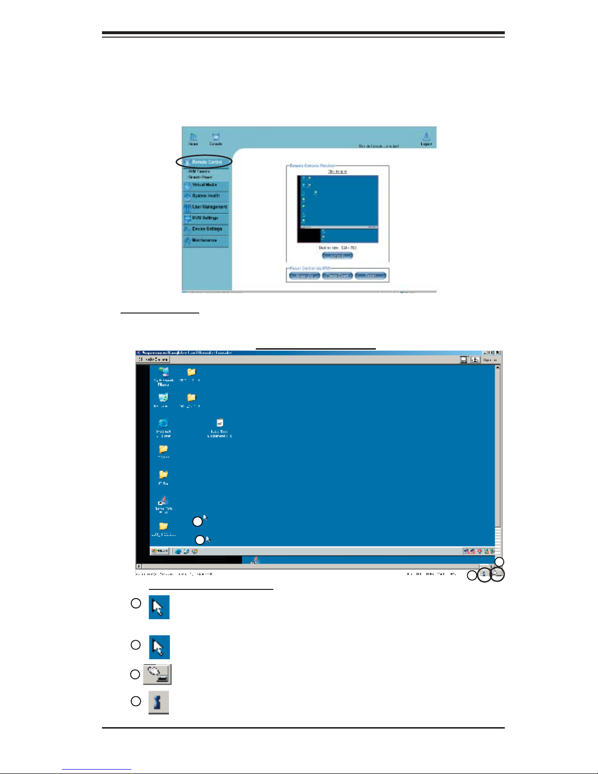
3.2.1. Remote Control
Click on the icon of Remote Control to activate its submenus-KVM Console and
Remote Power as listed below.
a. KVM Console
Click on this item to confi gure keyboard, mouse or video settings for the remote
host.
1
2
Remote Console Screen
4
Explanation of Functions
1
In the Single/Synchronized Mouse Mode, this cursor indicates the
system that is currently active. For the Double Mouse mode, this is the
cursor for the remote host.
2
This second mouse cursor only appears in the Double Mouse Mode.
This cursor represents the local mouse.
3
3
4
This icon indicates the availability of Keyboard and Mouse.
This icon indicates the number of networks (users) that are connected
via Console Redirection. (The number of fi gure icons indicates the
number of users connected.)
3-5
AOC-SIML1U-3B(+)/AOC-SIM1U-3D User's Guide
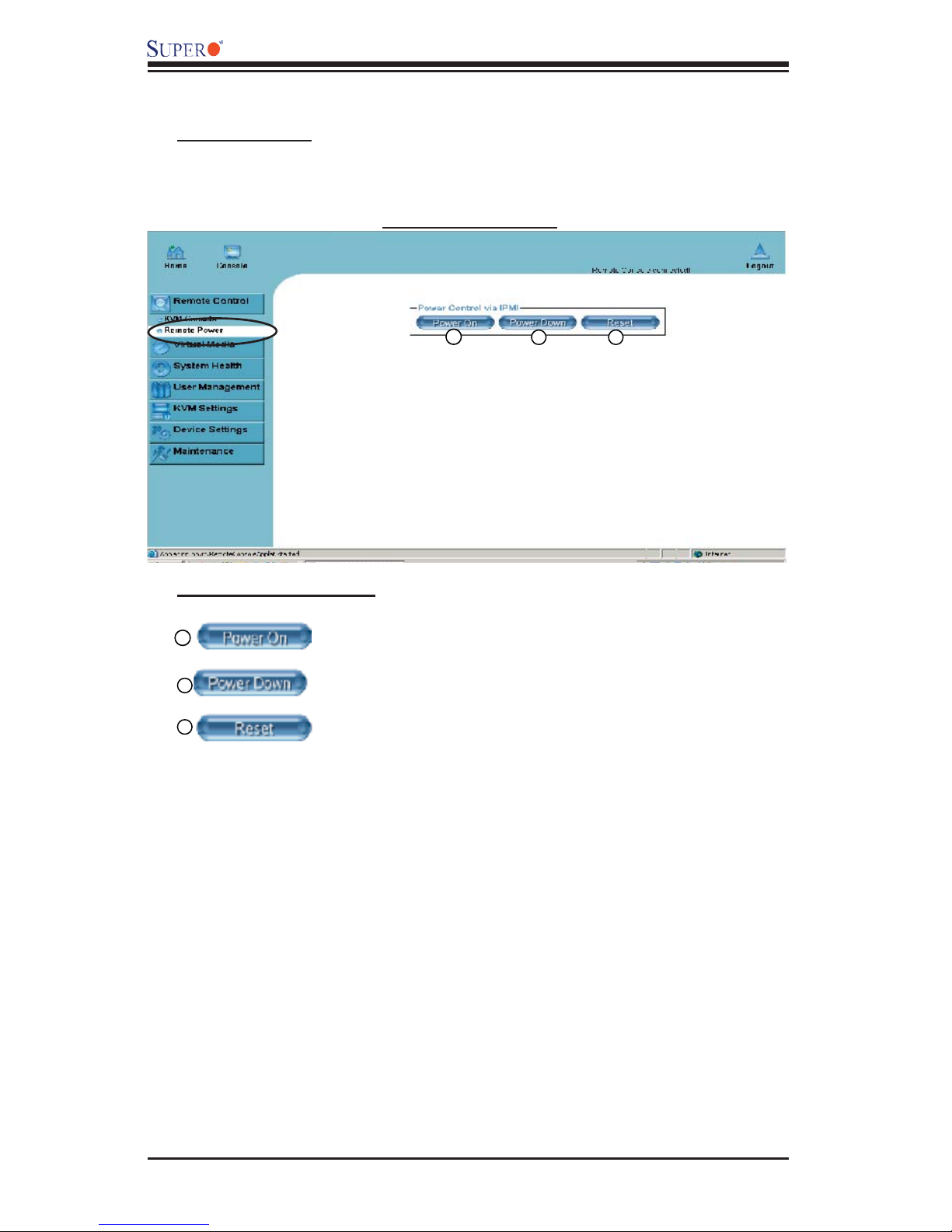
b. Remote Power
Click on this item to confi gure the power settings for Remote Console as shown
below.
Remote Power Screen
Explanation of Functions
1
2
3
Power On: Click on this icon to power on the remote host.
Power Down: Click on this icon to power down the remote
host.
Reset: Click on this icon to reset the remote host.
1
2 3
3-6

Chapter 3: Software Application and Usage
3.2.2. Virtual Media
Click on the Virtual Media icon on the Home Page to activate its submenus-Floppy
Disk, CD-ROM, Drive Redirection and Options as listed below.
a. Floppy disk
Floppy Disk Screen
2
1
Explanation of Functions
1
2
3
4
3
4
5
6
7
Floppy Disk: Click on this function key to upload the
data stored in the local fl oppy disk image to the remote
host.
Active Image (Drive1): This window displays the data
that has been uploaded to Drive 1 of the remote host.
Active Image (Drive2): This window displays the data
that has been uploaded to Drive 2 of the remote host.
Floppy Image Upload: This option allows the user to
upload the fl oppy image as "fl oppy" located in the remote
host. The fl oppy image uploaded shall be in the binary
format with a maximum size of 1.44MB. It will be loaded
to the Supermicro SIMLC card and will be emulated to
the host as a USB device.
5
6
7
Virtual Drive: Select a drive in the remote host as a
destination drive for you to upload your image data.
Floppy Image File: Click on "Browse" to preview and
select the fi les that you wish to upload to the host drive
selected.
Upload: Once the correct fi le name appears in the box,
click Upload to upload the fl oppy image to the drive
specifi ed in the remote host.
3-7
 Loading...